EP2527617A2 - A vortex reducer - Google Patents
A vortex reducer Download PDFInfo
- Publication number
- EP2527617A2 EP2527617A2 EP12167314A EP12167314A EP2527617A2 EP 2527617 A2 EP2527617 A2 EP 2527617A2 EP 12167314 A EP12167314 A EP 12167314A EP 12167314 A EP12167314 A EP 12167314A EP 2527617 A2 EP2527617 A2 EP 2527617A2
- Authority
- EP
- European Patent Office
- Prior art keywords
- flow
- rotor disc
- vortex
- vortex reducer
- passage
- Prior art date
- Legal status (The legal status is an assumption and is not a legal conclusion. Google has not performed a legal analysis and makes no representation as to the accuracy of the status listed.)
- Granted
Links
- 239000003638 chemical reducing agent Substances 0.000 title claims abstract description 66
- 238000000034 method Methods 0.000 claims description 13
- 238000011144 upstream manufacturing Methods 0.000 claims description 4
- 239000012530 fluid Substances 0.000 description 4
- 238000001816 cooling Methods 0.000 description 2
- 238000007789 sealing Methods 0.000 description 2
- 230000001133 acceleration Effects 0.000 description 1
- 230000015572 biosynthetic process Effects 0.000 description 1
- 238000004891 communication Methods 0.000 description 1
- 230000000694 effects Effects 0.000 description 1
Images



Classifications
-
- F—MECHANICAL ENGINEERING; LIGHTING; HEATING; WEAPONS; BLASTING
- F02—COMBUSTION ENGINES; HOT-GAS OR COMBUSTION-PRODUCT ENGINE PLANTS
- F02C—GAS-TURBINE PLANTS; AIR INTAKES FOR JET-PROPULSION PLANTS; CONTROLLING FUEL SUPPLY IN AIR-BREATHING JET-PROPULSION PLANTS
- F02C6/00—Plural gas-turbine plants; Combinations of gas-turbine plants with other apparatus; Adaptations of gas-turbine plants for special use
- F02C6/04—Gas-turbine plants providing heated or pressurised working fluid for other apparatus, e.g. without mechanical power output
- F02C6/06—Gas-turbine plants providing heated or pressurised working fluid for other apparatus, e.g. without mechanical power output providing compressed gas
- F02C6/08—Gas-turbine plants providing heated or pressurised working fluid for other apparatus, e.g. without mechanical power output providing compressed gas the gas being bled from the gas-turbine compressor
-
- F—MECHANICAL ENGINEERING; LIGHTING; HEATING; WEAPONS; BLASTING
- F04—POSITIVE - DISPLACEMENT MACHINES FOR LIQUIDS; PUMPS FOR LIQUIDS OR ELASTIC FLUIDS
- F04D—NON-POSITIVE-DISPLACEMENT PUMPS
- F04D29/00—Details, component parts, or accessories
- F04D29/26—Rotors specially for elastic fluids
- F04D29/32—Rotors specially for elastic fluids for axial flow pumps
- F04D29/321—Rotors specially for elastic fluids for axial flow pumps for axial flow compressors
Definitions
- the present disclosure relates to a vortex reducer for the guidance of bleed airflows and particularly but not exclusively relates to a vortex reducer for minimising pressure losses through bleed off-takes in axial compressors. Furthermore, the present disclosure relates a method for the guidance of bleed airflows by the vortex reducer.
- bleed airflows are branched off from a mainstream flow in the compressor to carry out the cooling of, or sealing between, certain components.
- the bleed airflows may be branched off between two adjacent rotor discs of the compressor, e.g. in the sixth stage of a high-pressure compressor.
- a portion of the mainstream flow may be bled into hole or passages provided in the compressor hub and passed through an inter-disc chamber between the two rotor discs in the direction of the shaft. In the inter-disc chamber, the bleed airflows form a free bleed air vortex which produces high pressure losses.
- the bleed airflows Once the bleed airflows have passed through the inter-disc chamber, they are guided downstream along the shaft into the area of the turbine to seal there, for example, the interspaces between the rotor discs of the turbine. Subsequently, the bleed air is discharged into the gas flow.
- vortex reducers may be used.
- a vortex reducer is advantageous in that the air is not increased in circumferential speed as it passes through the inter-disc chamber towards the shaft centre and, therefore, does not form a free vortex. Consequently, the pressure loss resulting therefrom is less than it would be with a non-vortex reduced system.
- Two types of vortex reducer are typically employed: tube-type vortex reducers and tubeless vortex reducers.
- tube-type vortex reducers are straight, radially inwardly directed tubular systems in which the air is positively guided. See for example Figure 1 (b) which shows a vortex tube 2 positioned between rotor discs 3, 4.
- Tube-type vortex reducers on the BR715 and BR725 engines at the HP4 location and the V2500 engine. Further examples can be found in US2004179936A , US2003101730A and US2009282834A .
- the vortex tubes constrain the air flowing through them to rotate at disc speed preventing the formation of a strong vortex and limiting the pressure drop.
- the tube-type vortex reducer is a heavy device and thus imposes a significant weight penalty. It is also mechanically difficult to implement and problems have been experienced with high cycle fatigue in some applications.
- the area of the tubes also limits the amount of flow that can be drawn through the system. Typically the air will have to be accelerated to disc speed at entry to the tubes and losses associated with this process increase the system pressure loss.
- Tubeless vortex reducers on the BR710 engine, see for example Figure 1 (c) in which bleed air 1 is guided between compressor discs 3, 4 by a guide vane 6.
- Figure 1 (c) in which bleed air 1 is guided between compressor discs 3, 4 by a guide vane 6.
- Tubeless vortex reducers utilise a nozzle or a nozzle guide vane built into the rotating assembly of the compressor towards the outer radius of the cavity. These de-swirl the air as it passes through them; that is they impart a tangential component of velocity to the air in the opposite direction to the rotation of the disc. This means that the air has minimal angular momentum at the outer radius of the cavity so the vortex that it forms as it flows radially inwards is weak, i.e. with a low tangential velocity. As a result there is a smaller pressure drop across the vortex reducer.
- the tubeless vortex reducer overcomes the problems associated with the tube-type vortex reducer, since they are relatively light and are mechanically simpler.
- Tubeless vortex reducers use the internal energy of the air to achieve the vortex reduction and so have lower losses than the tube-type vortex reducer and they have the potential to carry more through-flow as the frictional losses in the tube are eliminated.
- the tubeless vortex reducer has a complex flow characteristic which has meant that it has a history of behaving unexpectedly when used on engines.
- the flow characteristic is multi-valued, i.e. there is not a unique level of mass-flow associated with an imposed pressure ratio. This can lead to the device behaving unstably or not producing the expected level of bleed flow. As a result of this the tubeless design is not widely used despite its potential advantages.
- the multi-valued flow characteristic of the tubeless vortex reducer can be understood by considering the individual elements of the pressure loss, namely the de-swirl nozzle 6 and the subsequent vortex downstream of the de-swirl nozzle.
- the pressure loss through the nozzle will be small and the velocity exiting the nozzle will also be small. This means that very little de-swirl is achieved and the vortex inboard of the nozzle will be strong and have a high pressure drop.
- the same overall pressure drop can be realised at a higher mass-flow, e.g. in the high mass-flow region 12, where there is a relatively high pressure drop across the de-swirl nozzle and a significant reduction in the swirl velocity entering the vortex.
- This multi-valued characteristic is very undesirable in most air-system applications as it leads to uncertainty over the level of flow in the system if it should operate over the range of pressure ratios where the bistable behaviour is present.
- the present disclosure therefore seeks to address these issues.
- a vortex reducer for a bleed flow in an axial turbomachine comprising a rotor disc, the vortex reducer comprising one or more guide channels arrangeable adjacent to a first side of the rotor disc to at least partially de-swirl the bleed flow, wherein the vortex reducer further comprises a passage connecting the first side of the rotor disc to a high pressure flow source capable of providing a secondary flow to the first side of the rotor disc to mix with the bleed flow on the first side of the rotor disc.
- the secondary flow may flow from a second side of the rotor disc.
- the second side of the rotor disc may be at a higher pressure than the first side of the rotor disc due to the rotation of the rotor blades.
- the high pressure flow source may be on the second side of the rotor disc.
- the first side of the rotor disc may be upstream of the second side of the rotor disc, i.e. with respect to the mainstream flow through the compressor.
- the energy imparted by the compressor rotor may increase the pressure of the mainstream flow across the rotor and thus the pressure at the second side of the rotor disc may be higher than the pressure at the first side of the rotor disc.
- the first side of the rotor disc may be downstream of the second side of the rotor disc, i.e. with respect to the mainstream flow through the turbine.
- the energy imparted to the turbine rotor may reduce the pressure of the mainstream flow across the rotor and thus the pressure at the second side of the rotor disc may be higher than the pressure at the first side of the rotor disc.
- the passage may pass through an opening in the rotor disc.
- the passage may be provided through a securing means.
- the securing means may be hollow.
- the securing means may be adapted to secure the vortex reducer to the rotor disc.
- the securing means may comprise a nut and bolt assembly.
- An outlet of the passage may be provided on the first side of the rotor disc.
- the outlet may be provided upstream of the guide channel, i.e. upstream with respect to the bleed flow.
- the outlet of the passage may be provided downstream of the guide channel or the outlet of the passage may be provided within the guide channel.
- the guide channel may be defined by one or more guide portions adapted to guide and at least partially de-swirl the bleed flow.
- the guide portions may comprise guide vanes.
- the guide channel defined by the guide portions may comprise a radially angled passage.
- the guide portions may provide walls which may form the guide channel.
- the guide portions may be tubular.
- the outlet of the passage may be provided between adjacent guide portions, e.g. in the guide channel between adjacent guide vanes.
- the outlet of the passage may be provided in a further channel provided within a guide portion.
- the further channel may extend part way along the length of the guide portion and may extend from a downstream end of the guide portion.
- the further channel may be provided within the guide vane and the further channel may extend part way along the length of the vane from a trailing edge of the vane.
- a compressor, turbine or gas turbine may comprise the aforementioned vortex reducer.
- a method of reducing a vortex in a bleed flow within an axial turbomachine comprising a rotor disc, wherein the method comprises: at least partially de-swirling the bleed flow with one or more guide channels arrangeable adjacent to a first side of the rotor disc; passing a secondary flow from a high pressure flow source through a passage; and mixing the secondary flow from the high pressure flow source with the bleed flow on the first side of the rotor disc.
- the method may further comprise passing the high pressure secondary flow from a second side of the rotor disc, through the passage and to the first side of the rotor disc.
- the method may further comprise: providing the rotor disc with one or more rotor blades; and rotating the rotor disc such that the pressure is higher on the second side of the rotor disc.
- the vortex reducer and method disclosed herein may eliminate or substantially reduce the multi-valued region of the tubeless vortex reducer flow characteristic such that the vortex reducer may behave stably and reliably in engine operation.
- a vortex reducer 100 is configured to reduce the vortex in a bleed flow bled from a mainstream flow 102 within an axial compressor.
- the vortex reducer of the present disclosure may also be applied to an axial turbine.
- a mainstream flow 102 flows in a main annulus 101 between a hub wall 105 and casing wall 106 and flows from left to right as shown.
- a bleed flow 104 is bled off the mainstream flow 102.
- the bleed flow may be used for cooling, sealing or any other purpose.
- a bleed off-take may comprise an opening 107 in the hub wall and the opening may be inboard (e.g. adjacent to the hub) and/or mid-stage (e.g. between stages in a multistage axial turbomachine).
- the bleed off-take may be provided downstream of a first stator 112 and may direct flow towards the bore of the compressor drum between first and second rotor discs 111, 113.
- the rotor discs may comprise one or more rotor blades 111', 113'.
- the vortex reducer 100 may comprise one or more guide channels 122 arrangeable adjacent to a first side 113a of the rotor disc 113 to at least partially de-swirl the bleed flow 104.
- the guide channels 122 may be defined by one or more guide portions adapted to guide and at least partially de-swirl the bleed flow 104.
- the guide portions may comprise guide vanes 120.
- the bleed off-take may further comprise a tubeless vortex reducer, which in the embodiment shown in Figure 3(b) may comprise a set of nozzle guide vanes 120.
- the nozzle guide vanes 120 may impart a tangential velocity to the bleed flow, e.g. in the opposite direction to the rotation of the rotor disc 113.
- the bleed off-take may comprise a tube-type vortex reducer, e.g. tubes, which may be angled with respect to a radial component of the rotor disc 113.
- the vortex reducer 100 may further comprise a passage 130 connecting the first side 113a of the rotor disc to a high pressure flow source.
- the high pressure flow source may be capable of providing a secondary bleed flow 134 to the first side 113a of the rotor disc to mix with the bleed flow 104 on the first side of the rotor disc.
- the high pressure flow source may comprise fluid adjacent to a second side 113b of the rotor disc, e.g. from the cavity behind the second stage of rotor blades.
- the second side 113b of the rotor disc may be at a higher pressure than the first side of the rotor disc due to the rotation of the rotor blades.
- Mainstream flow 102 may be in fluid communication with fluid adjacent to the second side 113b of the rotor disc.
- the passage 130 may pass through an opening in the rotor disc 113 to provide high pressure fluid 134 to the bleed flow 104.
- the passage 130 may be provided through a securing means 132, which may be hollow.
- the securing means 132 may comprise a nut and bolt assembly, which may be adapted to secure the vortex reducer 100 to the rotor disc 113.
- An outlet 131 of the passage 130 may be provided on a first side 113a of the rotor disc
- the outlet 131 may be located in a further channel 124 provided within the guide vanes 120.
- the further channel 124 may extend part way along the length of a guide vane 120.
- the further channel 124 may extend from a trailing edge of the guide vane and towards a leading edge.
- the further bleed flow 134 from the second side 113b of the rotor disc may flow through the passage 130, out of the outlet 131 and through the further channel 124.
- the further bleed flow 134 may then mix with the bleed flow 104 at the trailing edge of the guide vanes 120.
- the further channel 124 may be a pilot de-swirl nozzle adapted to encourage a de-swirling flow in particular at low bleed mass-flow rates.
- Each guide vane 120 may comprise the further channel 124 or as shown not every guide vane 120 may comprise the further channel 124.
- the number of further channels 124 may be small relative to the number of guide channels 122.
- the flow area for the secondary bleed flow 134 may be relatively small with respect to the flow area for the bleed flow 104.
- Figure 4 shows the modified characteristic of the vortex reducer 100 according to the present disclosure.
- the additional bleed flow 134 may be relatively small so that it contributes a minimal amount to the total bleed flow and does not substantially influence the flow characteristic.
- the pilot nozzle guide vanes e.g. formed by further channels 124, may have a higher pressure drop due to their higher feed pressure.
- the pilot nozzles thus provide the majority of the flow at this point.
- the relatively high pressure drop across the pilot nozzles means that they also impart a significant de-swirl to the air.
- the pilot nozzles 124 therefore act to reduce the vortex at much lower mass-flow rates than the main nozzles 122 alone would do. This significantly reduces the bi-stable region of the tubeless vortex reducer characteristic and hence makes it more suitable for use in an air-system design.
- the present disclosure eliminates or substantially reduces the bistable region of the characteristic by introducing a second bleed of higher pressure air into the vortex reducer nozzles from a higher pressure source.
- This flow area for the further bleed flow 134 may be substantially smaller than the flow area for the bleed flow 104. Nevertheless, the further bleed flow 134 may act as a pilot de-swirl flow that reduces the vortex pressure loss at low mass flow rates until the main de-swirl flow is established at higher flow rates. Accordingly, a key advantage of the present disclosure over the previously-proposed vortex reducer is that it will operate in a stable and predictable manner over a much greater range of operating conditions. This is achieved by providing a second smaller set of de-swirl vanes or nozzles that act as a pilot flow to de-swirl the vortex at low levels of through-flow.
- the present disclosure may be based on a conventional tubeless vortex reducer, e.g. a device that may be employed when taking air bleeds radially inboard from compressors to reduce the pressure loss in the vortex flow between the compressor discs.
- a conventional tubeless vortex reducer e.g. a device that may be employed when taking air bleeds radially inboard from compressors to reduce the pressure loss in the vortex flow between the compressor discs.
- a conventional tubeless vortex reducer e.g. a device that may be employed when taking air bleeds radially inboard from compressors to reduce the pressure loss in the vortex flow between the compressor discs.
- a conventional tubeless vortex reducer e.g. a device that may be employed when taking air bleeds radially inboard from compressors to reduce the pressure loss in the vortex flow between the compressor discs.
- pilot de-swirl nozzles e.g. with respect to the number of guide nozzles
- this bi-stable region can
- the higher pressure flow source could be ducted to the pilot de-swirl nozzles in a variety of ways.
- the guide nozzles themselves may be guide vanes as shown, cylindrical drilled holes or any other guide channel.
Landscapes
- Engineering & Computer Science (AREA)
- Mechanical Engineering (AREA)
- General Engineering & Computer Science (AREA)
- Chemical & Material Sciences (AREA)
- Combustion & Propulsion (AREA)
- Structures Of Non-Positive Displacement Pumps (AREA)
Abstract

Description
- The present disclosure relates to a vortex reducer for the guidance of bleed airflows and particularly but not exclusively relates to a vortex reducer for minimising pressure losses through bleed off-takes in axial compressors. Furthermore, the present disclosure relates a method for the guidance of bleed airflows by the vortex reducer.
- In a gas turbine, bleed airflows are branched off from a mainstream flow in the compressor to carry out the cooling of, or sealing between, certain components. The bleed airflows may be branched off between two adjacent rotor discs of the compressor, e.g. in the sixth stage of a high-pressure compressor. By way of example, a portion of the mainstream flow may be bled into hole or passages provided in the compressor hub and passed through an inter-disc chamber between the two rotor discs in the direction of the shaft. In the inter-disc chamber, the bleed airflows form a free bleed air vortex which produces high pressure losses.
- Once the bleed airflows have passed through the inter-disc chamber, they are guided downstream along the shaft into the area of the turbine to seal there, for example, the interspaces between the rotor discs of the turbine. Subsequently, the bleed air is discharged into the gas flow.
- In a typical inboard bleed between compressor discs, conservation of angular momentum of the inwardly flowing and swirling air causes it to form a very strong vortex. The acceleration to very high tangential velocities at the disc bores results in a large pressure loss. An example of this kind of system is the IP5 system on the Trent 1000 engine, as shown in
Figure 1 (a) . As depicted, the bleed flow 1 flows through anopening 5 and radially inwardly betweenadjacent rotor discs - In order to minimize the pressure loss, vortex reducers may be used. A vortex reducer is advantageous in that the air is not increased in circumferential speed as it passes through the inter-disc chamber towards the shaft centre and, therefore, does not form a free vortex. Consequently, the pressure loss resulting therefrom is less than it would be with a non-vortex reduced system. Two types of vortex reducer are typically employed: tube-type vortex reducers and tubeless vortex reducers.
- In their simplest form, tube-type vortex reducers are straight, radially inwardly directed tubular systems in which the air is positively guided. See for example
Figure 1 (b) which shows avortex tube 2 positioned betweenrotor discs US2004179936A ,US2003101730A andUS2009282834A . The vortex tubes constrain the air flowing through them to rotate at disc speed preventing the formation of a strong vortex and limiting the pressure drop. - However, the tube-type vortex reducer is a heavy device and thus imposes a significant weight penalty. It is also mechanically difficult to implement and problems have been experienced with high cycle fatigue in some applications. The area of the tubes also limits the amount of flow that can be drawn through the system. Typically the air will have to be accelerated to disc speed at entry to the tubes and losses associated with this process increase the system pressure loss.
- There is an example of a tubeless vortex reducer on the BR710 engine, see for example
Figure 1 (c) in which bleed air 1 is guided betweencompressor discs guide vane 6. A further example can be found inUS6361277B1 . Tubeless vortex reducers utilise a nozzle or a nozzle guide vane built into the rotating assembly of the compressor towards the outer radius of the cavity. These de-swirl the air as it passes through them; that is they impart a tangential component of velocity to the air in the opposite direction to the rotation of the disc. This means that the air has minimal angular momentum at the outer radius of the cavity so the vortex that it forms as it flows radially inwards is weak, i.e. with a low tangential velocity. As a result there is a smaller pressure drop across the vortex reducer. - The tubeless vortex reducer overcomes the problems associated with the tube-type vortex reducer, since they are relatively light and are mechanically simpler. Tubeless vortex reducers use the internal energy of the air to achieve the vortex reduction and so have lower losses than the tube-type vortex reducer and they have the potential to carry more through-flow as the frictional losses in the tube are eliminated.
- However, the tubeless vortex reducer has a complex flow characteristic which has meant that it has a history of behaving unexpectedly when used on engines. With most tubeless vortex reducer designs there is a range of operating pressure ratios where the flow characteristic is multi-valued, i.e. there is not a unique level of mass-flow associated with an imposed pressure ratio. This can lead to the device behaving unstably or not producing the expected level of bleed flow. As a result of this the tubeless design is not widely used despite its potential advantages.
- With reference to
Figure 2 , the multi-valued flow characteristic of the tubeless vortex reducer can be understood by considering the individual elements of the pressure loss, namely thede-swirl nozzle 6 and the subsequent vortex downstream of the de-swirl nozzle. In a low mass-flow region 10 of the characteristic the pressure loss through the nozzle will be small and the velocity exiting the nozzle will also be small. This means that very little de-swirl is achieved and the vortex inboard of the nozzle will be strong and have a high pressure drop. The same overall pressure drop can be realised at a higher mass-flow, e.g. in the high mass-flow region 12, where there is a relatively high pressure drop across the de-swirl nozzle and a significant reduction in the swirl velocity entering the vortex. This means that the vortex is weak and has a relatively small pressure drop. In between the low and high mass-flow regions shaded region 16 shown inFigure 2 , the characteristic is bistable and at this range of pressure ratios the system can give either low or high flow. - This multi-valued characteristic is very undesirable in most air-system applications as it leads to uncertainty over the level of flow in the system if it should operate over the range of pressure ratios where the bistable behaviour is present.
- The present disclosure therefore seeks to address these issues.
- According to a first aspect of the present disclosure there is provided a vortex reducer for a bleed flow in an axial turbomachine comprising a rotor disc, the vortex reducer comprising one or more guide channels arrangeable adjacent to a first side of the rotor disc to at least partially de-swirl the bleed flow, wherein the vortex reducer further comprises a passage connecting the first side of the rotor disc to a high pressure flow source capable of providing a secondary flow to the first side of the rotor disc to mix with the bleed flow on the first side of the rotor disc.
- The secondary flow may flow from a second side of the rotor disc. The second side of the rotor disc may be at a higher pressure than the first side of the rotor disc due to the rotation of the rotor blades. The high pressure flow source may be on the second side of the rotor disc. For example, in the case of an axial compressor, the first side of the rotor disc may be upstream of the second side of the rotor disc, i.e. with respect to the mainstream flow through the compressor. The energy imparted by the compressor rotor may increase the pressure of the mainstream flow across the rotor and thus the pressure at the second side of the rotor disc may be higher than the pressure at the first side of the rotor disc.
- By contrast, in the case of an axial turbine, the first side of the rotor disc may be downstream of the second side of the rotor disc, i.e. with respect to the mainstream flow through the turbine. The energy imparted to the turbine rotor may reduce the pressure of the mainstream flow across the rotor and thus the pressure at the second side of the rotor disc may be higher than the pressure at the first side of the rotor disc.
- The passage may pass through an opening in the rotor disc. The passage may be provided through a securing means. As such the securing means may be hollow. The securing means may be adapted to secure the vortex reducer to the rotor disc. The securing means may comprise a nut and bolt assembly.
- An outlet of the passage may be provided on the first side of the rotor disc. The outlet may be provided upstream of the guide channel, i.e. upstream with respect to the bleed flow. Alternatively, the outlet of the passage may be provided downstream of the guide channel or the outlet of the passage may be provided within the guide channel.
- The guide channel may be defined by one or more guide portions adapted to guide and at least partially de-swirl the bleed flow. The guide portions may comprise guide vanes. The guide channel defined by the guide portions may comprise a radially angled passage. The guide portions may provide walls which may form the guide channel. The guide portions may be tubular.
- The outlet of the passage may be provided between adjacent guide portions, e.g. in the guide channel between adjacent guide vanes. Alternatively, the outlet of the passage may be provided in a further channel provided within a guide portion. The further channel may extend part way along the length of the guide portion and may extend from a downstream end of the guide portion. For example, in the case of the guide portions comprising guide vanes, the further channel may be provided within the guide vane and the further channel may extend part way along the length of the vane from a trailing edge of the vane.
- A compressor, turbine or gas turbine may comprise the aforementioned vortex reducer.
- According to a second aspect of the present disclosure there is provided a method of reducing a vortex in a bleed flow within an axial turbomachine comprising a rotor disc, wherein the method comprises: at least partially de-swirling the bleed flow with one or more guide channels arrangeable adjacent to a first side of the rotor disc; passing a secondary flow from a high pressure flow source through a passage; and mixing the secondary flow from the high pressure flow source with the bleed flow on the first side of the rotor disc.
- The method may further comprise passing the high pressure secondary flow from a second side of the rotor disc, through the passage and to the first side of the rotor disc.
- The method may further comprise: providing the rotor disc with one or more rotor blades; and rotating the rotor disc such that the pressure is higher on the second side of the rotor disc.
- The vortex reducer and method disclosed herein may eliminate or substantially reduce the multi-valued region of the tubeless vortex reducer flow characteristic such that the vortex reducer may behave stably and reliably in engine operation.
- For a better understanding of the present disclosure, and to show more clearly how it may be carried into effect, reference will now be made, by way of example, to the accompanying drawings, in which:-
-
Figure 1 shows three prior art arrangements withFigure 1(a) showing a bleed off-take with an unconstrained vortex,Figure 1 (b) showing a tube-type vortex reducer andFigure 1 (c) showing a tubeless vortex reducer; -
Figure 2 shows the mass-flow to pressure drop characteristic for a typical tubeless vortex reducer; -
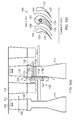
Figure 3 shows a vortex reducer according to an example of the present disclosure withFigure 3(a) showing a side sectional view of the turbomachine andFigure 3(b) showing a sectional view corresponding to section AA shown inFigure 3(a) ; and -
Figure 4 shows the mass-flow to pressure drop characteristic for the vortex reducer of the present disclosure compared with the corresponding characteristic for a typical tubeless vortex reducer. - With reference to
Figure 3 , avortex reducer 100, according to an example of the present disclosure, is configured to reduce the vortex in a bleed flow bled from amainstream flow 102 within an axial compressor. Although not shown, the vortex reducer of the present disclosure may also be applied to an axial turbine. - A
mainstream flow 102 flows in amain annulus 101 between ahub wall 105 andcasing wall 106 and flows from left to right as shown. Ableed flow 104 is bled off themainstream flow 102. The bleed flow may be used for cooling, sealing or any other purpose. A bleed off-take may comprise anopening 107 in the hub wall and the opening may be inboard (e.g. adjacent to the hub) and/or mid-stage (e.g. between stages in a multistage axial turbomachine). For example, the bleed off-take may be provided downstream of afirst stator 112 and may direct flow towards the bore of the compressor drum between first andsecond rotor discs - The
vortex reducer 100 may comprise one ormore guide channels 122 arrangeable adjacent to afirst side 113a of therotor disc 113 to at least partially de-swirl thebleed flow 104. Theguide channels 122 may be defined by one or more guide portions adapted to guide and at least partially de-swirl thebleed flow 104. The guide portions may compriseguide vanes 120. For example, the bleed off-take may further comprise a tubeless vortex reducer, which in the embodiment shown inFigure 3(b) may comprise a set of nozzle guide vanes 120. Thenozzle guide vanes 120 may impart a tangential velocity to the bleed flow, e.g. in the opposite direction to the rotation of therotor disc 113. Alternatively, the bleed off-take may comprise a tube-type vortex reducer, e.g. tubes, which may be angled with respect to a radial component of therotor disc 113. - The
vortex reducer 100 may further comprise apassage 130 connecting thefirst side 113a of the rotor disc to a high pressure flow source. The high pressure flow source may be capable of providing asecondary bleed flow 134 to thefirst side 113a of the rotor disc to mix with thebleed flow 104 on the first side of the rotor disc. - In the example shown in
Figure 3 , the high pressure flow source may comprise fluid adjacent to asecond side 113b of the rotor disc, e.g. from the cavity behind the second stage of rotor blades. Thesecond side 113b of the rotor disc may be at a higher pressure than the first side of the rotor disc due to the rotation of the rotor blades.Mainstream flow 102 may be in fluid communication with fluid adjacent to thesecond side 113b of the rotor disc. - The
passage 130 may pass through an opening in therotor disc 113 to providehigh pressure fluid 134 to thebleed flow 104. Thepassage 130 may be provided through a securing means 132, which may be hollow. The securing means 132 may comprise a nut and bolt assembly, which may be adapted to secure thevortex reducer 100 to therotor disc 113. - An
outlet 131 of thepassage 130 may be provided on afirst side 113a of the rotor disc Theoutlet 131 may be located in afurther channel 124 provided within the guide vanes 120. Thefurther channel 124 may extend part way along the length of aguide vane 120. Thefurther channel 124 may extend from a trailing edge of the guide vane and towards a leading edge. As a result, thefurther bleed flow 134 from thesecond side 113b of the rotor disc may flow through thepassage 130, out of theoutlet 131 and through thefurther channel 124. Thefurther bleed flow 134 may then mix with thebleed flow 104 at the trailing edge of the guide vanes 120. Thefurther channel 124 may be a pilot de-swirl nozzle adapted to encourage a de-swirling flow in particular at low bleed mass-flow rates. - Each
guide vane 120 may comprise thefurther channel 124 or as shown not every guide vane 120 may comprise thefurther channel 124. The number offurther channels 124 may be small relative to the number ofguide channels 122. The flow area for thesecondary bleed flow 134 may be relatively small with respect to the flow area for thebleed flow 104. -
Figure 4 shows the modified characteristic of thevortex reducer 100 according to the present disclosure. In the high mass-flow region 212 theadditional bleed flow 134 may be relatively small so that it contributes a minimal amount to the total bleed flow and does not substantially influence the flow characteristic. However in the low mass-flow region 210 of the characteristic there is very little pressure drop across themain guide nozzles 120, whereas the pilot nozzle guide vanes, e.g. formed byfurther channels 124, may have a higher pressure drop due to their higher feed pressure. The pilot nozzles thus provide the majority of the flow at this point. The relatively high pressure drop across the pilot nozzles means that they also impart a significant de-swirl to the air. The pilot nozzles 124 therefore act to reduce the vortex at much lower mass-flow rates than themain nozzles 122 alone would do. This significantly reduces the bi-stable region of the tubeless vortex reducer characteristic and hence makes it more suitable for use in an air-system design. - The present disclosure eliminates or substantially reduces the bistable region of the characteristic by introducing a second bleed of higher pressure air into the vortex reducer nozzles from a higher pressure source. This flow area for the
further bleed flow 134 may be substantially smaller than the flow area for thebleed flow 104. Nevertheless, thefurther bleed flow 134 may act as a pilot de-swirl flow that reduces the vortex pressure loss at low mass flow rates until the main de-swirl flow is established at higher flow rates. Accordingly, a key advantage of the present disclosure over the previously-proposed vortex reducer is that it will operate in a stable and predictable manner over a much greater range of operating conditions. This is achieved by providing a second smaller set of de-swirl vanes or nozzles that act as a pilot flow to de-swirl the vortex at low levels of through-flow. - The present disclosure may be based on a conventional tubeless vortex reducer, e.g. a device that may be employed when taking air bleeds radially inboard from compressors to reduce the pressure loss in the vortex flow between the compressor discs. Over a range of operating pressures such devices may be bi-stable and this can lead to the devices passing a bleed flow which is significantly lower than required. However, by incorporating a relatively small number of pilot de-swirl nozzles (e.g. with respect to the number of guide nozzles) fed from a higher pressure source of air, this bi-stable region can be substantially reduced or eliminated. This can be used to ensure the device passes a reliable level of flow.
- There may be a number of alternative configurations to the embodiment shown. The higher pressure flow source could be ducted to the pilot de-swirl nozzles in a variety of ways. The guide nozzles themselves may be guide vanes as shown, cylindrical drilled holes or any other guide channel.
Claims (15)
- A vortex reducer (100) for a bleed flow (104) in an axial turbomachine comprising a rotor disc (113), the vortex reducer comprising one or more guide channels (122) arrangeable adjacent to a first side (113a) of the rotor disc to at least partially de-swirl the bleed flow, wherein the vortex reducer further comprises a passage (130) connectable to a high pressure flow source, the passage being adapted to provide a secondary flow (134) from the high pressure flow source to mix with the bleed flow on the first side of the rotor disc.
- The vortex reducer as claimed in claim 1, wherein the secondary flow comes from a second side (113b) of the rotor disc.
- The vortex reducer as claimed in claim 2, wherein the rotor disc is provided with one or more rotor blades (113') and the second side of the rotor disc is at a higher pressure than the first side of the rotor disc due to rotation of the rotor blades.
- The vortex reducer as claimed in claim 2 or 3, wherein the passage passes through an opening in the rotor disc.
- The vortex reducer as claimed in any of claims 2 to 4, wherein the passage is provided through a securing means (132), the securing means being adapted to secure the vortex reducer to the rotor disc.
- The vortex reducer as claimed in any preceding claim, wherein an outlet of the passage is provided upstream of the guide channel.
- The vortex reducer as claimed in any of claims 1 to 5, wherein an outlet of the passage is provided downstream of the guide channel.
- The vortex reducer as claimed in any of claims 1 to 5, wherein an outlet of the passage is provided within the guide channel.
- The vortex reducer of any preceding claim, wherein the guide channel is defined by one or more guide portions (120) adapted to guide and at least partially de-swirl the bleed flow.
- The vortex reducer of claim 9, wherein an outlet of the passage is provided between adjacent guide portions.
- The vortex reducer of claim 9, wherein an outlet (131) of the passage is provided in a further channel (124) provided within the guide portions.
- A compressor, turbine or gas turbine comprising the vortex reducer of any of claims 1 to 11.
- A method of reducing a vortex in a bleed flow (104) within an axial turbomachine comprising a rotor disc (113), wherein the method comprises:at least partially de-swirling the bleed flow with one or more guide channels (122) arrangeable adjacent to a first side (113a) of the rotor disc;passing a secondary flow (134) from a high pressure flow source through a passage (130); andmixing the secondary flow from the high pressure flow source with the bleed flow on the first side of the rotor disc.
- The method of claim 13, wherein the method further comprises:passing the secondary flow from a second side (113b) of the rotor disc, through the passage and to the first side of the rotor disc.
- The method of claim 13, wherein the method further comprises:providing the rotor disc with one or more rotor blades (113'); androtating the rotor disc such that the pressure is higher on the second side of the rotor disc.
Applications Claiming Priority (1)
| Application Number | Priority Date | Filing Date | Title |
|---|---|---|---|
| GBGB1108842.4A GB201108842D0 (en) | 2011-05-26 | 2011-05-26 | A vortex reducer |
Publications (3)
| Publication Number | Publication Date |
|---|---|
| EP2527617A2 true EP2527617A2 (en) | 2012-11-28 |
| EP2527617A3 EP2527617A3 (en) | 2017-11-01 |
| EP2527617B1 EP2527617B1 (en) | 2019-01-23 |
Family
ID=44279638
Family Applications (1)
| Application Number | Title | Priority Date | Filing Date |
|---|---|---|---|
| EP12167314.9A Not-in-force EP2527617B1 (en) | 2011-05-26 | 2012-05-09 | A vortex reducer |
Country Status (3)
| Country | Link |
|---|---|
| US (1) | US9228495B2 (en) |
| EP (1) | EP2527617B1 (en) |
| GB (1) | GB201108842D0 (en) |
Families Citing this family (4)
| Publication number | Priority date | Publication date | Assignee | Title |
|---|---|---|---|---|
| CN107975822B (en) * | 2017-12-19 | 2023-03-14 | 中国科学院工程热物理研究所 | Combustion chamber of gas turbine and gas turbine using combustion chamber |
| CN110454436B (en) * | 2019-07-29 | 2021-04-16 | 中国航发沈阳发动机研究所 | Short bending type vortex reducing plate applied to high-position air entraining of aero-engine compressor |
| US11352903B2 (en) * | 2020-01-20 | 2022-06-07 | Raytheon Technologies Corporation | Rotor stack bushing with adaptive temperature metering for a gas turbine engine |
| CN114837816B (en) * | 2022-05-31 | 2024-05-28 | 北京航空航天大学 | Variable angle's deflector formula vortex breaker |
Citations (4)
| Publication number | Priority date | Publication date | Assignee | Title |
|---|---|---|---|---|
| US6361277B1 (en) | 2000-01-24 | 2002-03-26 | General Electric Company | Methods and apparatus for directing airflow to a compressor bore |
| US20030101730A1 (en) | 2001-12-05 | 2003-06-05 | Stefan Hein | Vortex reducer in the high-pressure compressor of a gas turbine |
| US20040179936A1 (en) | 2003-03-12 | 2004-09-16 | Ian Fitzgerald | Tube-type vortex reducer with retaining ring |
| US20090282834A1 (en) | 2008-05-19 | 2009-11-19 | Stefan Hein | Combined Vortex reducer |
Family Cites Families (10)
| Publication number | Priority date | Publication date | Assignee | Title |
|---|---|---|---|---|
| DE3627306A1 (en) * | 1986-02-28 | 1987-09-03 | Mtu Muenchen Gmbh | DEVICE FOR VENTILATING ROTOR COMPONENTS FOR COMPRESSORS OF GAS TURBINE ENGINE PLANTS |
| DE3606597C1 (en) * | 1986-02-28 | 1987-02-19 | Mtu Muenchen Gmbh | Blade and sealing gap optimization device for compressors of gas turbine engines |
| GB2207465B (en) | 1987-07-18 | 1992-02-19 | Rolls Royce Plc | A compressor and air bleed arrangement |
| JP3758835B2 (en) * | 1997-10-22 | 2006-03-22 | 三菱重工業株式会社 | Clearance control method by cooling air compressor disk |
| US6428272B1 (en) * | 2000-12-22 | 2002-08-06 | General Electric Company | Bolted joint for rotor disks and method of reducing thermal gradients therein |
| FR2834753B1 (en) * | 2002-01-17 | 2004-09-03 | Snecma Moteurs | TURBOMACHINE AXIAL COMPRESSOR DISC WITH CENTRIPTED AIR TAKE-OFF |
| DE102004042295A1 (en) * | 2004-09-01 | 2006-03-02 | Mtu Aero Engines Gmbh | Rotor for an engine |
| FR2930588B1 (en) * | 2008-04-24 | 2010-06-04 | Snecma | COMPRESSOR ROTOR OF A TURBOMACHINE HAVING CENTRIFIC AIR-LEVELING MEANS |
| US8465252B2 (en) * | 2009-04-17 | 2013-06-18 | United Technologies Corporation | Turbine engine rotating cavity anti-vortex cascade |
| US8177503B2 (en) | 2009-04-17 | 2012-05-15 | United Technologies Corporation | Turbine engine rotating cavity anti-vortex cascade |
-
2011
- 2011-05-26 GB GBGB1108842.4A patent/GB201108842D0/en not_active Ceased
-
2012
- 2012-05-09 EP EP12167314.9A patent/EP2527617B1/en not_active Not-in-force
- 2012-05-09 US US13/467,423 patent/US9228495B2/en not_active Expired - Fee Related
Patent Citations (4)
| Publication number | Priority date | Publication date | Assignee | Title |
|---|---|---|---|---|
| US6361277B1 (en) | 2000-01-24 | 2002-03-26 | General Electric Company | Methods and apparatus for directing airflow to a compressor bore |
| US20030101730A1 (en) | 2001-12-05 | 2003-06-05 | Stefan Hein | Vortex reducer in the high-pressure compressor of a gas turbine |
| US20040179936A1 (en) | 2003-03-12 | 2004-09-16 | Ian Fitzgerald | Tube-type vortex reducer with retaining ring |
| US20090282834A1 (en) | 2008-05-19 | 2009-11-19 | Stefan Hein | Combined Vortex reducer |
Also Published As
| Publication number | Publication date |
|---|---|
| EP2527617A3 (en) | 2017-11-01 |
| US9228495B2 (en) | 2016-01-05 |
| US20120301272A1 (en) | 2012-11-29 |
| EP2527617B1 (en) | 2019-01-23 |
| GB201108842D0 (en) | 2011-07-06 |
Similar Documents
| Publication | Publication Date | Title |
|---|---|---|
| JP5802380B2 (en) | Multistage fan | |
| US8047777B2 (en) | Turbomachine diffuser | |
| EP2333238A2 (en) | Gas turbine engine with outer fans | |
| CA2816613C (en) | Blade with an s-shaped profile for an axial turbomachine compressor | |
| US20110052373A1 (en) | High-turning diffuser strut with flow cross-over slots | |
| CN102016233B (en) | Centripetal air bleed from a turbomachine compressor rotor | |
| EP2484912B1 (en) | Wet gas compressor systems | |
| JP2012521419A5 (en) | ||
| US11585347B2 (en) | Mixed-flow compressor configuration for a refrigeration system | |
| US20200378603A1 (en) | Fuel spray nozzle arrangement | |
| EP3231997A1 (en) | Gas turbine engine airfoil bleed | |
| EP3791047A1 (en) | Outlet guide vane | |
| EP2527617B1 (en) | A vortex reducer | |
| WO2014078370A1 (en) | An exhaust gas diffuser for a gas turbine | |
| US7828514B2 (en) | Rotor for an engine | |
| US9903382B2 (en) | Axial compressor for fluid-flow machines | |
| US9695694B2 (en) | Aircraft engine blading | |
| CA2964988C (en) | Assembly and method for influencing flow through a fan of a gas turbine engine | |
| CN103114876B (en) | Impact type air turbine machine and wavy hair power plant | |
| CN112955661A (en) | Centrifugal or mixed flow compressor comprising a suction diffuser | |
| EP2778346B1 (en) | Rotor for a gas turbine engine, corresponding gas turbine engine and method of improving gas turbine engine rotor efficiency | |
| WO2014149099A1 (en) | Centrifugal compressor with axial impeller exit | |
| EP3290650A1 (en) | Low-pressure steam turbine diffuser for reducing shock losses | |
| US11401835B2 (en) | Turbine center frame | |
| RU2012124190A (en) | MULTI-STAGE TURBO MACHINE |
Legal Events
| Date | Code | Title | Description |
|---|---|---|---|
| PUAI | Public reference made under article 153(3) epc to a published international application that has entered the european phase |
Free format text: ORIGINAL CODE: 0009012 |
|
| AK | Designated contracting states |
Kind code of ref document: A2 Designated state(s): AL AT BE BG CH CY CZ DE DK EE ES FI FR GB GR HR HU IE IS IT LI LT LU LV MC MK MT NL NO PL PT RO RS SE SI SK SM TR |
|
| AX | Request for extension of the european patent |
Extension state: BA ME |
|
| RAP1 | Party data changed (applicant data changed or rights of an application transferred) |
Owner name: ROLLS-ROYCE PLC |
|
| PUAL | Search report despatched |
Free format text: ORIGINAL CODE: 0009013 |
|
| AK | Designated contracting states |
Kind code of ref document: A3 Designated state(s): AL AT BE BG CH CY CZ DE DK EE ES FI FR GB GR HR HU IE IS IT LI LT LU LV MC MK MT NL NO PL PT RO RS SE SI SK SM TR |
|
| AX | Request for extension of the european patent |
Extension state: BA ME |
|
| RIC1 | Information provided on ipc code assigned before grant |
Ipc: F04D 29/32 20060101ALI20170927BHEP Ipc: F02C 6/08 20060101AFI20170927BHEP |
|
| STAA | Information on the status of an ep patent application or granted ep patent |
Free format text: STATUS: REQUEST FOR EXAMINATION WAS MADE |
|
| 17P | Request for examination filed |
Effective date: 20180427 |
|
| RBV | Designated contracting states (corrected) |
Designated state(s): AL AT BE BG CH CY CZ DE DK EE ES FI FR GB GR HR HU IE IS IT LI LT LU LV MC MK MT NL NO PL PT RO RS SE SI SK SM TR |
|
| STAA | Information on the status of an ep patent application or granted ep patent |
Free format text: STATUS: EXAMINATION IS IN PROGRESS |
|
| 17Q | First examination report despatched |
Effective date: 20180629 |
|
| GRAP | Despatch of communication of intention to grant a patent |
Free format text: ORIGINAL CODE: EPIDOSNIGR1 |
|
| STAA | Information on the status of an ep patent application or granted ep patent |
Free format text: STATUS: GRANT OF PATENT IS INTENDED |
|
| GRAS | Grant fee paid |
Free format text: ORIGINAL CODE: EPIDOSNIGR3 |
|
| GRAA | (expected) grant |
Free format text: ORIGINAL CODE: 0009210 |
|
| STAA | Information on the status of an ep patent application or granted ep patent |
Free format text: STATUS: THE PATENT HAS BEEN GRANTED |
|
| INTG | Intention to grant announced |
Effective date: 20181126 |
|
| AK | Designated contracting states |
Kind code of ref document: B1 Designated state(s): AL AT BE BG CH CY CZ DE DK EE ES FI FR GB GR HR HU IE IS IT LI LT LU LV MC MK MT NL NO PL PT RO RS SE SI SK SM TR |
|
| REG | Reference to a national code |
Ref country code: GB Ref legal event code: FG4D |
|
| REG | Reference to a national code |
Ref country code: CH Ref legal event code: EP |
|
| REG | Reference to a national code |
Ref country code: AT Ref legal event code: REF Ref document number: 1091634 Country of ref document: AT Kind code of ref document: T Effective date: 20190215 |
|
| REG | Reference to a national code |
Ref country code: IE Ref legal event code: FG4D |
|
| REG | Reference to a national code |
Ref country code: DE Ref legal event code: R096 Ref document number: 602012056141 Country of ref document: DE |
|
| REG | Reference to a national code |
Ref country code: NL Ref legal event code: MP Effective date: 20190123 |
|
| PG25 | Lapsed in a contracting state [announced via postgrant information from national office to epo] |
Ref country code: NL Free format text: LAPSE BECAUSE OF FAILURE TO SUBMIT A TRANSLATION OF THE DESCRIPTION OR TO PAY THE FEE WITHIN THE PRESCRIBED TIME-LIMIT Effective date: 20190123 |
|
| PG25 | Lapsed in a contracting state [announced via postgrant information from national office to epo] |
Ref country code: ES Free format text: LAPSE BECAUSE OF FAILURE TO SUBMIT A TRANSLATION OF THE DESCRIPTION OR TO PAY THE FEE WITHIN THE PRESCRIBED TIME-LIMIT Effective date: 20190123 Ref country code: LT Free format text: LAPSE BECAUSE OF FAILURE TO SUBMIT A TRANSLATION OF THE DESCRIPTION OR TO PAY THE FEE WITHIN THE PRESCRIBED TIME-LIMIT Effective date: 20190123 Ref country code: NO Free format text: LAPSE BECAUSE OF FAILURE TO SUBMIT A TRANSLATION OF THE DESCRIPTION OR TO PAY THE FEE WITHIN THE PRESCRIBED TIME-LIMIT Effective date: 20190423 Ref country code: FI Free format text: LAPSE BECAUSE OF FAILURE TO SUBMIT A TRANSLATION OF THE DESCRIPTION OR TO PAY THE FEE WITHIN THE PRESCRIBED TIME-LIMIT Effective date: 20190123 Ref country code: PL Free format text: LAPSE BECAUSE OF FAILURE TO SUBMIT A TRANSLATION OF THE DESCRIPTION OR TO PAY THE FEE WITHIN THE PRESCRIBED TIME-LIMIT Effective date: 20190123 Ref country code: SE Free format text: LAPSE BECAUSE OF FAILURE TO SUBMIT A TRANSLATION OF THE DESCRIPTION OR TO PAY THE FEE WITHIN THE PRESCRIBED TIME-LIMIT Effective date: 20190123 Ref country code: PT Free format text: LAPSE BECAUSE OF FAILURE TO SUBMIT A TRANSLATION OF THE DESCRIPTION OR TO PAY THE FEE WITHIN THE PRESCRIBED TIME-LIMIT Effective date: 20190523 |
|
| PGFP | Annual fee paid to national office [announced via postgrant information from national office to epo] |
Ref country code: DE Payment date: 20190530 Year of fee payment: 8 |
|
| REG | Reference to a national code |
Ref country code: AT Ref legal event code: MK05 Ref document number: 1091634 Country of ref document: AT Kind code of ref document: T Effective date: 20190123 |
|
| PG25 | Lapsed in a contracting state [announced via postgrant information from national office to epo] |
Ref country code: BG Free format text: LAPSE BECAUSE OF FAILURE TO SUBMIT A TRANSLATION OF THE DESCRIPTION OR TO PAY THE FEE WITHIN THE PRESCRIBED TIME-LIMIT Effective date: 20190423 Ref country code: GR Free format text: LAPSE BECAUSE OF FAILURE TO SUBMIT A TRANSLATION OF THE DESCRIPTION OR TO PAY THE FEE WITHIN THE PRESCRIBED TIME-LIMIT Effective date: 20190424 Ref country code: HR Free format text: LAPSE BECAUSE OF FAILURE TO SUBMIT A TRANSLATION OF THE DESCRIPTION OR TO PAY THE FEE WITHIN THE PRESCRIBED TIME-LIMIT Effective date: 20190123 Ref country code: RS Free format text: LAPSE BECAUSE OF FAILURE TO SUBMIT A TRANSLATION OF THE DESCRIPTION OR TO PAY THE FEE WITHIN THE PRESCRIBED TIME-LIMIT Effective date: 20190123 Ref country code: LV Free format text: LAPSE BECAUSE OF FAILURE TO SUBMIT A TRANSLATION OF THE DESCRIPTION OR TO PAY THE FEE WITHIN THE PRESCRIBED TIME-LIMIT Effective date: 20190123 Ref country code: IS Free format text: LAPSE BECAUSE OF FAILURE TO SUBMIT A TRANSLATION OF THE DESCRIPTION OR TO PAY THE FEE WITHIN THE PRESCRIBED TIME-LIMIT Effective date: 20190523 |
|
| PGFP | Annual fee paid to national office [announced via postgrant information from national office to epo] |
Ref country code: FR Payment date: 20190527 Year of fee payment: 8 |
|
| REG | Reference to a national code |
Ref country code: DE Ref legal event code: R097 Ref document number: 602012056141 Country of ref document: DE |
|
| PG25 | Lapsed in a contracting state [announced via postgrant information from national office to epo] |
Ref country code: CZ Free format text: LAPSE BECAUSE OF FAILURE TO SUBMIT A TRANSLATION OF THE DESCRIPTION OR TO PAY THE FEE WITHIN THE PRESCRIBED TIME-LIMIT Effective date: 20190123 Ref country code: SK Free format text: LAPSE BECAUSE OF FAILURE TO SUBMIT A TRANSLATION OF THE DESCRIPTION OR TO PAY THE FEE WITHIN THE PRESCRIBED TIME-LIMIT Effective date: 20190123 Ref country code: RO Free format text: LAPSE BECAUSE OF FAILURE TO SUBMIT A TRANSLATION OF THE DESCRIPTION OR TO PAY THE FEE WITHIN THE PRESCRIBED TIME-LIMIT Effective date: 20190123 Ref country code: AL Free format text: LAPSE BECAUSE OF FAILURE TO SUBMIT A TRANSLATION OF THE DESCRIPTION OR TO PAY THE FEE WITHIN THE PRESCRIBED TIME-LIMIT Effective date: 20190123 Ref country code: EE Free format text: LAPSE BECAUSE OF FAILURE TO SUBMIT A TRANSLATION OF THE DESCRIPTION OR TO PAY THE FEE WITHIN THE PRESCRIBED TIME-LIMIT Effective date: 20190123 Ref country code: DK Free format text: LAPSE BECAUSE OF FAILURE TO SUBMIT A TRANSLATION OF THE DESCRIPTION OR TO PAY THE FEE WITHIN THE PRESCRIBED TIME-LIMIT Effective date: 20190123 Ref country code: IT Free format text: LAPSE BECAUSE OF FAILURE TO SUBMIT A TRANSLATION OF THE DESCRIPTION OR TO PAY THE FEE WITHIN THE PRESCRIBED TIME-LIMIT Effective date: 20190123 |
|
| PGFP | Annual fee paid to national office [announced via postgrant information from national office to epo] |
Ref country code: GB Payment date: 20190528 Year of fee payment: 8 |
|
| PG25 | Lapsed in a contracting state [announced via postgrant information from national office to epo] |
Ref country code: SM Free format text: LAPSE BECAUSE OF FAILURE TO SUBMIT A TRANSLATION OF THE DESCRIPTION OR TO PAY THE FEE WITHIN THE PRESCRIBED TIME-LIMIT Effective date: 20190123 |
|
| PLBE | No opposition filed within time limit |
Free format text: ORIGINAL CODE: 0009261 |
|
| STAA | Information on the status of an ep patent application or granted ep patent |
Free format text: STATUS: NO OPPOSITION FILED WITHIN TIME LIMIT |
|
| REG | Reference to a national code |
Ref country code: CH Ref legal event code: PL |
|
| PG25 | Lapsed in a contracting state [announced via postgrant information from national office to epo] |
Ref country code: AT Free format text: LAPSE BECAUSE OF FAILURE TO SUBMIT A TRANSLATION OF THE DESCRIPTION OR TO PAY THE FEE WITHIN THE PRESCRIBED TIME-LIMIT Effective date: 20190123 |
|
| 26N | No opposition filed |
Effective date: 20191024 |
|
| PG25 | Lapsed in a contracting state [announced via postgrant information from national office to epo] |
Ref country code: CH Free format text: LAPSE BECAUSE OF NON-PAYMENT OF DUE FEES Effective date: 20190531 Ref country code: MC Free format text: LAPSE BECAUSE OF FAILURE TO SUBMIT A TRANSLATION OF THE DESCRIPTION OR TO PAY THE FEE WITHIN THE PRESCRIBED TIME-LIMIT Effective date: 20190123 Ref country code: LI Free format text: LAPSE BECAUSE OF NON-PAYMENT OF DUE FEES Effective date: 20190531 |
|
| REG | Reference to a national code |
Ref country code: BE Ref legal event code: MM Effective date: 20190531 |
|
| PG25 | Lapsed in a contracting state [announced via postgrant information from national office to epo] |
Ref country code: SI Free format text: LAPSE BECAUSE OF FAILURE TO SUBMIT A TRANSLATION OF THE DESCRIPTION OR TO PAY THE FEE WITHIN THE PRESCRIBED TIME-LIMIT Effective date: 20190123 Ref country code: LU Free format text: LAPSE BECAUSE OF NON-PAYMENT OF DUE FEES Effective date: 20190509 |
|
| PG25 | Lapsed in a contracting state [announced via postgrant information from national office to epo] |
Ref country code: TR Free format text: LAPSE BECAUSE OF FAILURE TO SUBMIT A TRANSLATION OF THE DESCRIPTION OR TO PAY THE FEE WITHIN THE PRESCRIBED TIME-LIMIT Effective date: 20190123 |
|
| PG25 | Lapsed in a contracting state [announced via postgrant information from national office to epo] |
Ref country code: IE Free format text: LAPSE BECAUSE OF NON-PAYMENT OF DUE FEES Effective date: 20190509 |
|
| PG25 | Lapsed in a contracting state [announced via postgrant information from national office to epo] |
Ref country code: BE Free format text: LAPSE BECAUSE OF NON-PAYMENT OF DUE FEES Effective date: 20190531 |
|
| REG | Reference to a national code |
Ref country code: DE Ref legal event code: R119 Ref document number: 602012056141 Country of ref document: DE |
|
| GBPC | Gb: european patent ceased through non-payment of renewal fee |
Effective date: 20200509 |
|
| PG25 | Lapsed in a contracting state [announced via postgrant information from national office to epo] |
Ref country code: GB Free format text: LAPSE BECAUSE OF NON-PAYMENT OF DUE FEES Effective date: 20200509 Ref country code: FR Free format text: LAPSE BECAUSE OF NON-PAYMENT OF DUE FEES Effective date: 20200531 |
|
| PG25 | Lapsed in a contracting state [announced via postgrant information from national office to epo] |
Ref country code: CY Free format text: LAPSE BECAUSE OF FAILURE TO SUBMIT A TRANSLATION OF THE DESCRIPTION OR TO PAY THE FEE WITHIN THE PRESCRIBED TIME-LIMIT Effective date: 20190123 Ref country code: DE Free format text: LAPSE BECAUSE OF NON-PAYMENT OF DUE FEES Effective date: 20201201 |
|
| PG25 | Lapsed in a contracting state [announced via postgrant information from national office to epo] |
Ref country code: HU Free format text: LAPSE BECAUSE OF FAILURE TO SUBMIT A TRANSLATION OF THE DESCRIPTION OR TO PAY THE FEE WITHIN THE PRESCRIBED TIME-LIMIT; INVALID AB INITIO Effective date: 20120509 Ref country code: MT Free format text: LAPSE BECAUSE OF FAILURE TO SUBMIT A TRANSLATION OF THE DESCRIPTION OR TO PAY THE FEE WITHIN THE PRESCRIBED TIME-LIMIT Effective date: 20190123 |
|
| PG25 | Lapsed in a contracting state [announced via postgrant information from national office to epo] |
Ref country code: MK Free format text: LAPSE BECAUSE OF FAILURE TO SUBMIT A TRANSLATION OF THE DESCRIPTION OR TO PAY THE FEE WITHIN THE PRESCRIBED TIME-LIMIT Effective date: 20190123 |