EP2527598A2 - Gas turbine compressor last stage rotor blades with axial retention - Google Patents
Gas turbine compressor last stage rotor blades with axial retention Download PDFInfo
- Publication number
- EP2527598A2 EP2527598A2 EP12169388A EP12169388A EP2527598A2 EP 2527598 A2 EP2527598 A2 EP 2527598A2 EP 12169388 A EP12169388 A EP 12169388A EP 12169388 A EP12169388 A EP 12169388A EP 2527598 A2 EP2527598 A2 EP 2527598A2
- Authority
- EP
- European Patent Office
- Prior art keywords
- retention key
- blade
- rotor
- retention
- rotor blade
- Prior art date
- Legal status (The legal status is an assumption and is not a legal conclusion. Google has not performed a legal analysis and makes no representation as to the accuracy of the status listed.)
- Withdrawn
Links
- 230000014759 maintenance of location Effects 0.000 title claims abstract description 64
- 238000009434 installation Methods 0.000 description 2
- 238000000034 method Methods 0.000 description 2
- 230000001154 acute effect Effects 0.000 description 1
- 150000001875 compounds Chemical class 0.000 description 1
- 238000010276 construction Methods 0.000 description 1
- 238000003780 insertion Methods 0.000 description 1
- 230000037431 insertion Effects 0.000 description 1
- 238000012986 modification Methods 0.000 description 1
- 230000004048 modification Effects 0.000 description 1
- 238000009877 rendering Methods 0.000 description 1
- 230000000717 retained effect Effects 0.000 description 1
- 239000007787 solid Substances 0.000 description 1
Images


Classifications
-
- F—MECHANICAL ENGINEERING; LIGHTING; HEATING; WEAPONS; BLASTING
- F01—MACHINES OR ENGINES IN GENERAL; ENGINE PLANTS IN GENERAL; STEAM ENGINES
- F01D—NON-POSITIVE DISPLACEMENT MACHINES OR ENGINES, e.g. STEAM TURBINES
- F01D5/00—Blades; Blade-carrying members; Heating, heat-insulating, cooling or antivibration means on the blades or the members
- F01D5/30—Fixing blades to rotors; Blade roots ; Blade spacers
- F01D5/32—Locking, e.g. by final locking blades or keys
- F01D5/323—Locking of axial insertion type blades by means of a key or the like parallel to the axis of the rotor
-
- F—MECHANICAL ENGINEERING; LIGHTING; HEATING; WEAPONS; BLASTING
- F01—MACHINES OR ENGINES IN GENERAL; ENGINE PLANTS IN GENERAL; STEAM ENGINES
- F01D—NON-POSITIVE DISPLACEMENT MACHINES OR ENGINES, e.g. STEAM TURBINES
- F01D5/00—Blades; Blade-carrying members; Heating, heat-insulating, cooling or antivibration means on the blades or the members
- F01D5/30—Fixing blades to rotors; Blade roots ; Blade spacers
- F01D5/3007—Fixing blades to rotors; Blade roots ; Blade spacers of axial insertion type
-
- F—MECHANICAL ENGINEERING; LIGHTING; HEATING; WEAPONS; BLASTING
- F01—MACHINES OR ENGINES IN GENERAL; ENGINE PLANTS IN GENERAL; STEAM ENGINES
- F01D—NON-POSITIVE DISPLACEMENT MACHINES OR ENGINES, e.g. STEAM TURBINES
- F01D5/00—Blades; Blade-carrying members; Heating, heat-insulating, cooling or antivibration means on the blades or the members
- F01D5/30—Fixing blades to rotors; Blade roots ; Blade spacers
- F01D5/32—Locking, e.g. by final locking blades or keys
- F01D5/326—Locking of axial insertion type blades by other means
-
- F—MECHANICAL ENGINEERING; LIGHTING; HEATING; WEAPONS; BLASTING
- F04—POSITIVE - DISPLACEMENT MACHINES FOR LIQUIDS; PUMPS FOR LIQUIDS OR ELASTIC FLUIDS
- F04D—NON-POSITIVE-DISPLACEMENT PUMPS
- F04D29/00—Details, component parts, or accessories
- F04D29/26—Rotors specially for elastic fluids
- F04D29/32—Rotors specially for elastic fluids for axial flow pumps
- F04D29/321—Rotors specially for elastic fluids for axial flow pumps for axial flow compressors
- F04D29/322—Blade mountings
-
- F—MECHANICAL ENGINEERING; LIGHTING; HEATING; WEAPONS; BLASTING
- F05—INDEXING SCHEMES RELATING TO ENGINES OR PUMPS IN VARIOUS SUBCLASSES OF CLASSES F01-F04
- F05D—INDEXING SCHEME FOR ASPECTS RELATING TO NON-POSITIVE-DISPLACEMENT MACHINES OR ENGINES, GAS-TURBINES OR JET-PROPULSION PLANTS
- F05D2220/00—Application
- F05D2220/30—Application in turbines
- F05D2220/32—Application in turbines in gas turbines
- F05D2220/321—Application in turbines in gas turbines for a special turbine stage
- F05D2220/3216—Application in turbines in gas turbines for a special turbine stage for a special compressor stage
- F05D2220/3219—Application in turbines in gas turbines for a special turbine stage for a special compressor stage for the last stage of a compressor or a high pressure compressor
-
- F—MECHANICAL ENGINEERING; LIGHTING; HEATING; WEAPONS; BLASTING
- F05—INDEXING SCHEMES RELATING TO ENGINES OR PUMPS IN VARIOUS SUBCLASSES OF CLASSES F01-F04
- F05D—INDEXING SCHEME FOR ASPECTS RELATING TO NON-POSITIVE-DISPLACEMENT MACHINES OR ENGINES, GAS-TURBINES OR JET-PROPULSION PLANTS
- F05D2250/00—Geometry
- F05D2250/40—Movement of components
- F05D2250/41—Movement of components with one degree of freedom
- F05D2250/411—Movement of components with one degree of freedom in rotation
-
- F—MECHANICAL ENGINEERING; LIGHTING; HEATING; WEAPONS; BLASTING
- F05—INDEXING SCHEMES RELATING TO ENGINES OR PUMPS IN VARIOUS SUBCLASSES OF CLASSES F01-F04
- F05D—INDEXING SCHEME FOR ASPECTS RELATING TO NON-POSITIVE-DISPLACEMENT MACHINES OR ENGINES, GAS-TURBINES OR JET-PROPULSION PLANTS
- F05D2260/00—Function
- F05D2260/30—Retaining components in desired mutual position
- F05D2260/33—Retaining components in desired mutual position with a bayonet coupling
-
- F—MECHANICAL ENGINEERING; LIGHTING; HEATING; WEAPONS; BLASTING
- F05—INDEXING SCHEMES RELATING TO ENGINES OR PUMPS IN VARIOUS SUBCLASSES OF CLASSES F01-F04
- F05D—INDEXING SCHEME FOR ASPECTS RELATING TO NON-POSITIVE-DISPLACEMENT MACHINES OR ENGINES, GAS-TURBINES OR JET-PROPULSION PLANTS
- F05D2260/00—Function
- F05D2260/30—Retaining components in desired mutual position
- F05D2260/36—Retaining components in desired mutual position by a form fit connection, e.g. by interlocking
Definitions
- the present invention relates generally to rotor wheels in turbine engines and specifically to the retention of blades within slots provided in the rotor wheel.
- individual blades are loaded into substantially axially-oriented slots or grooves formed in the rotor wheel.
- the blades must be retained in the slots or grooves so as to prevent any radial or axial movement of the blades during operation of the turbine.
- Dovetail mountings on the blades and complimentary dovetail slots in the wheel serve to prevent radial movement.
- various techniques for preventing blade movement in the axial direction some of which involve "staking" of the ends of the blade dovetails after insertion into the complimentary slots. For the rotor wheel or disc in the last stage of certain compressors, however there is little or no access to the front or back of the blade dovetail, rendering the staking method unfeasible.
- the invention resides in a rotor blade and blade retention key, the blade comprising a radially outer airfoil, a shank and a radially inner attachment dovetail; the attachment dovetail having a radially innermost surface formed with a notch at one axial end thereof, and the retention key received in the notch and rotatable from a retracted position wherein a retention key portion is substantially flush with the radially innermost surface, to an extended position wherein the retention key portion projects radially substantially inwardly from the radially innermost surface.
- the invention resides, in a rotor wheel fitted with a plurality of rotor blades, each rotor blade comprising the above rotor blade and blade retention key, wherein the rotor wheel is formed with plural substantially axially extending slots, each receiving one of the radially inner attachment dovetails of the blades; a radially inner surface of one or more of the axially-extending slots formed with a recess; wherein the retention key is received in the recess to thereby prevent axial movement of the rotor blade within the slot.
- a plurality of blades or buckets are loaded into generally axially-oriented slots or grooves in the axially-spaced rotor wheels.
- the individual blades or buckets 10 typically include a radially outer airfoil portion (not shown), a shank portion (not shown) and a radially inner dovetail mounting portion 12.
- the dovetail mounting portion 12 (or simply, “dovetail”) is slidably received in the slot or groove 14 formed in the rotor wheel 16.
- the slot or groove 14 is formed with sidewalls 18 complimentary to the dovetail 12 such that the bucket is fixed against any radial movement within the slot once the blade or bucket 10 is installed in its respective wheel slot or groove 14. It is also important, however, to prevent any axial movement of the bucket within the slot.
- a rotatable axial retention key 20 as shown in Fig. 3 , is provided that is formed to include an axial retention key portion 22 and an actuation portion 24 extending therefrom.
- the retention key portion 22 is formed in a substantially truncated cylindrical shape with a circumferential surface 26 subtending an arc of approximately 220°, and terminating at opposite ends of a flat surface 28.
- the key actuating portion 24 extends substantially perpendicularly from a flat edge 30 of the retention key portion 22 and is in the form of a solid shaft 32 terminating at a flat, angled end face 34.
- the end face 34 may be provided one or more slots 38, described further below, for receiving a corresponding edge(s) of an actuation tool when it is desired to rotate the retention key 20.
- one end of the radially innermost surface 36 of the dovetail 12 of the bucket 10 is partially shown and is formed with a substantially axially extending, compound notch 40 that includes a relatively larger diametrical recess 42 that opens to a relatively smaller diametrical recess 44 designed to receive the retention key 20.
- the notch 40 is sized such that the larger recess 42 is shaped to receive the retention key portion 26 and the smaller recess 44 is shaped to receive the actuation portion 24.
- the retention key 20 fits within the notch 40 as best seen in Fig. 4 where the retention key 20 is shown in a retracted position, with the flat surface 28 substantially flush with the radially innermost surface 36 of the dovetail 12. Note also that the actuation portion 24 is at all times flush with or radially recessed from surface 36. As also shown in Fig. 4 , the angled end face 34 of the shaft 22 is formed with a tool-engagement surface feature which, in the example embodiment, includes a pair of intersecting slots (or a cross slot) 38, so that a Phillips-head screwdriver may be employed to rotate the retention key 20 from the retracted position shown in Fig. 4 to the extended position shown in Fig. 5 .
- the shape of the tool receiving slot or slots may vary depending on the tool to be used to rotate the retention key.
- the retention key 20 is shown rotated 90° in a counterclockwise direction relative to its orientation in Fig. 4 .
- a portion of the retention key portion 22 moves into a recess or pocket 42 formed in the bottom surface of the wheel slot in which the dovetail 26 is received.
- the recess or pocket 42 formed in the flat, substantially axially-extending surface 44 of the wheel slot 14 may have a shape generally similar to the exposed portion of the retention key portion 22 shown in Fig. 4 , with a limit surface 46 on one side of the recess that, for example, allows rotation of the retention key 20 only about 90° in the counterclockwise direction. By so limiting the rotation, it is communicated to the user that the retention key 20 has been rotated to its finally-extended position. Further in this regard, it will be appreciated that the dimensions of the pocket or recess 42 are critical only in the axial direction, but not in the transverse direction.
- the key portion 22 must fit within the recess or pocket 42 with close axial tolerances to substantially eliminate any axial movement of the dovetail 26 within the wheel slot 14.
- the dimensions of the pocket or recess in the transverse direction are not particularly critical except in the case where a limit surface, such as surface 46, is provided to limit the extent of the rotation of the retention key 20.
- the flat end face 34 of the key actuating portion or shaft 22 is angled so that when the axial retention key 20 is in the extended position, the end face 34 will be substantially flush with the end surface 48 of the dovetail 12. Note that this is not the case when the axial retention key 20 is shown in the retracted position ( Fig. 3 ). This is because the end surface 48 of the dovetail 12 is not square to the rotor wheel. In other words, the wheel slots 12 in which the blades are received extend at an acute angle in the axial direction relative to the rotor shaft, so that the blades are properly oriented relative to the incoming flow across the blades.
Landscapes
- Engineering & Computer Science (AREA)
- Mechanical Engineering (AREA)
- General Engineering & Computer Science (AREA)
- Structures Of Non-Positive Displacement Pumps (AREA)
- Turbine Rotor Nozzle Sealing (AREA)
Abstract
A rotor blade and blade retention key assembly includes: a radially outer airfoil, a shank and a radially inner attachment dovetail. The attachment dovetail has a radially innermost surface (36) formed with a notch (40) at one axial end thereof, and a retention key is received in the notch (40), and rotatable from a retracted position where a retention key portion is substantially flush with the radially innermost surface (36), to an extended position where the retention key portion projects inwardly from said radially innermost surface (36) and into a recess (42,44) or pocket formed in a rotor wheel slot to prevent axial movement of the blade within the slot.
Description
- The present invention relates generally to rotor wheels in turbine engines and specifically to the retention of blades within slots provided in the rotor wheel.
- In certain turbine engine configurations, individual blades are loaded into substantially axially-oriented slots or grooves formed in the rotor wheel. The blades must be retained in the slots or grooves so as to prevent any radial or axial movement of the blades during operation of the turbine. Dovetail mountings on the blades and complimentary dovetail slots in the wheel serve to prevent radial movement. There have been devised various techniques for preventing blade movement in the axial direction, some of which involve "staking" of the ends of the blade dovetails after insertion into the complimentary slots. For the rotor wheel or disc in the last stage of certain compressors, however there is little or no access to the front or back of the blade dovetail, rendering the staking method unfeasible.
- There remains a need, therefore, for a blade retention mechanism that is easy to install and remove, and that provides effective and reliable blade retention in the axial direction.
- Accordingly, in a first aspect, the invention resides in a rotor blade and blade retention key, the blade comprising a radially outer airfoil, a shank and a radially inner attachment dovetail; the attachment dovetail having a radially innermost surface formed with a notch at one axial end thereof, and the retention key received in the notch and rotatable from a retracted position wherein a retention key portion is substantially flush with the radially innermost surface, to an extended position wherein the retention key portion projects radially substantially inwardly from the radially innermost surface.
- In another aspect, the invention resides, in a rotor wheel fitted with a plurality of rotor blades, each rotor blade comprising the above rotor blade and blade retention key, wherein the rotor wheel is formed with plural substantially axially extending slots, each receiving one of the radially inner attachment dovetails of the blades; a radially inner surface of one or more of the axially-extending slots formed with a recess; wherein the retention key is received in the recess to thereby prevent axial movement of the rotor blade within the slot.
- Embodiments of the present invention will now be described, by way of example only, with reference to the accompanying drawings in which:
-
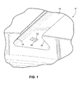
Fig. 1 is a partial perspective view of a rotor wheel dovetail slot formed with a key-receiving recess in accordance with an exemplary but nonlimiting embodiment of the invention; -
Fig. 2 is a partial perspective view of a radially inner surface of a bucket dovetail formed with a groove for mounting a retention key in accordance with the exemplary but nonlimiting embodiment of the invention; -
Fig. 3 is a perspective view of a retention key for use with the bucket dovetail shown inFig. 2 ; -
Fig. 4 is a partial perspective view showing the retention key ofFig. 3 installed within the bucket dovetail shown inFig. 2 in a retracted position; -
Fig. 5 is a partial perspective view similar toFig. 4 but showing the retention key rotated to an extended position. - For certain well-known turbine compressor rotor constructions, a plurality of blades or buckets are loaded into generally axially-oriented slots or grooves in the axially-spaced rotor wheels. With reference initially to
Figs. 1 and2 , the individual blades orbuckets 10 typically include a radially outer airfoil portion (not shown), a shank portion (not shown) and a radially innerdovetail mounting portion 12. The dovetail mounting portion 12 (or simply, "dovetail") is slidably received in the slot orgroove 14 formed in therotor wheel 16. The slot orgroove 14 is formed withsidewalls 18 complimentary to thedovetail 12 such that the bucket is fixed against any radial movement within the slot once the blade orbucket 10 is installed in its respective wheel slot orgroove 14. It is also important, however, to prevent any axial movement of the bucket within the slot. - Accordingly, a rotatable
axial retention key 20 as shown inFig. 3 , is provided that is formed to include an axialretention key portion 22 and anactuation portion 24 extending therefrom. More specifically, theretention key portion 22 is formed in a substantially truncated cylindrical shape with acircumferential surface 26 subtending an arc of approximately 220°, and terminating at opposite ends of aflat surface 28. The key actuatingportion 24 extends substantially perpendicularly from aflat edge 30 of theretention key portion 22 and is in the form of asolid shaft 32 terminating at a flat,angled end face 34. As will be described further herein, theend face 34 may be provided one ormore slots 38, described further below, for receiving a corresponding edge(s) of an actuation tool when it is desired to rotate theretention key 20. - As best seen in
Fig. 2 , one end of the radiallyinnermost surface 36 of thedovetail 12 of thebucket 10 is partially shown and is formed with a substantially axially extending,compound notch 40 that includes a relatively largerdiametrical recess 42 that opens to a relatively smallerdiametrical recess 44 designed to receive theretention key 20. Specifically, thenotch 40 is sized such that thelarger recess 42 is shaped to receive theretention key portion 26 and thesmaller recess 44 is shaped to receive theactuation portion 24. - The
retention key 20 fits within thenotch 40 as best seen inFig. 4 where theretention key 20 is shown in a retracted position, with theflat surface 28 substantially flush with the radiallyinnermost surface 36 of thedovetail 12. Note also that theactuation portion 24 is at all times flush with or radially recessed fromsurface 36. As also shown inFig. 4 , theangled end face 34 of theshaft 22 is formed with a tool-engagement surface feature which, in the example embodiment, includes a pair of intersecting slots (or a cross slot) 38, so that a Phillips-head screwdriver may be employed to rotate theretention key 20 from the retracted position shown inFig. 4 to the extended position shown inFig. 5 . The shape of the tool receiving slot or slots may vary depending on the tool to be used to rotate the retention key. InFig. 5 , theretention key 20 is shown rotated 90° in a counterclockwise direction relative to its orientation inFig. 4 . A portion of theretention key portion 22 moves into a recess orpocket 42 formed in the bottom surface of the wheel slot in which thedovetail 26 is received. - With reference again to
Fig. 1 , the recess orpocket 42 formed in the flat, substantially axially-extendingsurface 44 of thewheel slot 14 may have a shape generally similar to the exposed portion of theretention key portion 22 shown inFig. 4 , with alimit surface 46 on one side of the recess that, for example, allows rotation of theretention key 20 only about 90° in the counterclockwise direction. By so limiting the rotation, it is communicated to the user that theretention key 20 has been rotated to its finally-extended position. Further in this regard, it will be appreciated that the dimensions of the pocket orrecess 42 are critical only in the axial direction, but not in the transverse direction. In other words, thekey portion 22 must fit within the recess orpocket 42 with close axial tolerances to substantially eliminate any axial movement of thedovetail 26 within thewheel slot 14. The dimensions of the pocket or recess in the transverse direction are not particularly critical except in the case where a limit surface, such assurface 46, is provided to limit the extent of the rotation of theretention key 20. - It is also noted that the
flat end face 34 of the key actuating portion orshaft 22 is angled so that when theaxial retention key 20 is in the extended position, theend face 34 will be substantially flush with theend surface 48 of thedovetail 12. Note that this is not the case when theaxial retention key 20 is shown in the retracted position (Fig. 3 ). This is because theend surface 48 of thedovetail 12 is not square to the rotor wheel. In other words, thewheel slots 12 in which the blades are received extend at an acute angle in the axial direction relative to the rotor shaft, so that the blades are properly oriented relative to the incoming flow across the blades. - It is also to be noted that no separate means need be provided to hold the
retention key 20 in thenotch 40 prior to installation. The retention key and blade or airfoil are loaded manually into the wheel slot orgroove 12, and theretention key 20 may be held in place while the airfoil is loaded into the slot or groove. After installation, theend face 34 may be staked as shown at 48, 50 to prevent rotation of the key to the retracted portion - While the invention has been described in connection with what is presently considered to be the most practical and preferred embodiment, it is to be understood that the invention is not to be limited to the disclosed embodiment, but on the contrary, is intended to cover various modifications and equivalent arrangements included within the spirit and scope of the appended claims
Claims (11)
- A rotor blade and blade retention key comprising:the blade comprising a radially outer airfoil, a shank and a radially inner attachment dovetail; said attachment dovetail having a radially innermost surface (36) formed with a notch (40) at one axial end thereof, and a retention key (20) received in said notch (40) of the radically innermost surface (36) of the attachment dovetail, and rotatable from a retracted position wherein a retention key portion (22) is substantially flush with said radially innermost surface (36), to an extended position wherein said retention key portion (22) projects radially substantially inwardly from said radially innermost surface (36).
- The rotor blade and blade retention key of claim 1, wherein said retention key (20) includes an axially extending shaft portion (32) integral with said retention key portion (22) that remains inset from, or substantially flush with, said radially innermost surface (36) during rotation of said retention key (20) from said retracted position to said extended position.
- The rotor blade and blade retention key of claim 2, wherein said axially extending shaft portion (32) has an end face (34) flush with a side surface (48) of said attachment dovetail when said retention key (20) is in said extended position, said end face (34) having a tool-engagement surface feature enabling rotation of said retention key (20) between said retracted position and said extended position.
- The rotor blade and blade retention key of claim 2 or 3, wherein said retention key portion (22) is substantially perpendicular to said axially-extending shaft portion (32).
- The rotor blade and blade retention key of claim 3, wherein said tool-engagement surface feature is a cross slot.
- The rotor blade and blade retention key of any preceding claim, wherein said retention key portion (22) has a truncated cylinder-shape including a flat surface (28) that is substantially flush with said radially innermost surface (36) with said retention key (20) is in said retracted position.
- The rotor blade and blade retention key of any of claims 3 to 6, wherein said notch (40) includes a first transverse notch area for receiving said retention key portion (22), and an axial notch area for receiving said axially extending shaft portion (32).
- The rotor blade and blade retention key of any preceding claim, wherein rotation from said retracted position to said extended position subtends an arc of about ninety degrees.
- The rotor blade and blade retention key of any of claims 6 to 8, wherein said retention key portion has an arcuate surface extending about 220° connected at opposite ends to said flat surface (28).
- A rotor wheel (16) fitted with a plurality of rotor blades each rotor blade comprising the rotor blade and blade retention key of any of claims 1 to 9, wherein said rotor wheel (16) formed with plural substantially axially extending slots (38), each receiving one of said radially inner attachment dovetails of the blades; the radially inner surface (36) of one or more of said axially-extending slots (38) formed with a recess (42) is received in said recess (42) to thereby prevent axial movement of said rotor blade within said slot (38).
- The rotor wheel of claim 10 wherein said recess has a limit surface engageable by said flat surface when said retention key is rotated to said extended position.
Applications Claiming Priority (1)
| Application Number | Priority Date | Filing Date | Title |
|---|---|---|---|
| US13/116,068 US8727733B2 (en) | 2011-05-26 | 2011-05-26 | Gas turbine compressor last stage rotor blades with axial retention |
Publications (1)
| Publication Number | Publication Date |
|---|---|
| EP2527598A2 true EP2527598A2 (en) | 2012-11-28 |
Family
ID=47196946
Family Applications (1)
| Application Number | Title | Priority Date | Filing Date |
|---|---|---|---|
| EP12169388A Withdrawn EP2527598A2 (en) | 2011-05-26 | 2012-05-24 | Gas turbine compressor last stage rotor blades with axial retention |
Country Status (3)
| Country | Link |
|---|---|
| US (1) | US8727733B2 (en) |
| EP (1) | EP2527598A2 (en) |
| CN (1) | CN102797699B (en) |
Cited By (1)
| Publication number | Priority date | Publication date | Assignee | Title |
|---|---|---|---|---|
| CN110397625A (en) * | 2019-08-15 | 2019-11-01 | 上海电气燃气轮机有限公司 | A New Blade Locking Device |
Families Citing this family (9)
| Publication number | Priority date | Publication date | Assignee | Title |
|---|---|---|---|---|
| EP2808490A1 (en) * | 2013-05-29 | 2014-12-03 | Alstom Technology Ltd | Turbine blade with locking pin |
| CN103628928B (en) * | 2013-11-29 | 2015-03-11 | 东方电气集团东方汽轮机有限公司 | Fir blade root final blade axial direction positioning structure |
| US9664058B2 (en) | 2014-12-31 | 2017-05-30 | General Electric Company | Flowpath boundary and rotor assemblies in gas turbines |
| US9777586B2 (en) | 2014-12-31 | 2017-10-03 | General Electric Company | Flowpath boundary and rotor assemblies in gas turbines |
| US10400784B2 (en) | 2015-05-27 | 2019-09-03 | United Technologies Corporation | Fan blade attachment root with improved strain response |
| US9506357B1 (en) | 2015-12-08 | 2016-11-29 | General Electric Company | Turbomachine staking tool |
| US10465537B2 (en) * | 2016-05-27 | 2019-11-05 | General Electric Company | Margin bucket dovetail radial support feature for axial entry buckets |
| US11098729B2 (en) | 2016-08-04 | 2021-08-24 | General Electric Company | Gas turbine wheel assembly, method of modifying a compressor wheel, and method of mounting a blade to a gas turbine wheel |
| CN108757569A (en) * | 2018-06-07 | 2018-11-06 | 哈尔滨电气股份有限公司 | Novel pressure mechanism of qi blade and wheel disc connection structure |
Family Cites Families (6)
| Publication number | Priority date | Publication date | Assignee | Title |
|---|---|---|---|---|
| US5518369A (en) | 1994-12-15 | 1996-05-21 | Pratt & Whitney Canada Inc. | Gas turbine blade retention |
| KR100568183B1 (en) * | 2004-01-08 | 2006-04-05 | 삼성전자주식회사 | Turbo compressor |
| US7517197B2 (en) * | 2006-10-25 | 2009-04-14 | General Electric Company | Airfoil shape for a compressor |
| US8267664B2 (en) * | 2008-04-04 | 2012-09-18 | General Electric Company | Axial compressor blade retention |
| US20100054929A1 (en) * | 2008-09-04 | 2010-03-04 | General Electric Company | Turbine airfoil clocking |
| US8251668B2 (en) * | 2009-06-30 | 2012-08-28 | General Electric Company | Method and apparatus for assembling rotating machines |
-
2011
- 2011-05-26 US US13/116,068 patent/US8727733B2/en not_active Expired - Fee Related
-
2012
- 2012-05-24 EP EP12169388A patent/EP2527598A2/en not_active Withdrawn
- 2012-05-25 CN CN201210182938.0A patent/CN102797699B/en not_active Expired - Fee Related
Non-Patent Citations (1)
| Title |
|---|
| None |
Cited By (1)
| Publication number | Priority date | Publication date | Assignee | Title |
|---|---|---|---|---|
| CN110397625A (en) * | 2019-08-15 | 2019-11-01 | 上海电气燃气轮机有限公司 | A New Blade Locking Device |
Also Published As
| Publication number | Publication date |
|---|---|
| CN102797699A (en) | 2012-11-28 |
| US8727733B2 (en) | 2014-05-20 |
| US20120301308A1 (en) | 2012-11-29 |
| CN102797699B (en) | 2016-08-10 |
Similar Documents
| Publication | Publication Date | Title |
|---|---|---|
| US8727733B2 (en) | Gas turbine compressor last stage rotor blades with axial retention | |
| CN107208490B (en) | The fixed device of blade with the locking device for turbo blade | |
| CN101529052B (en) | Turbine blade assembly | |
| US20110176923A1 (en) | Seal plate and bucket retention pin assembly | |
| US7534090B2 (en) | Enhanced bucket vibration system | |
| JP6106021B2 (en) | Turbine assembly | |
| US8061995B2 (en) | Machine component retention | |
| EP2505785B1 (en) | Seal assembly for a blade dovetail and corresponding sealing method | |
| US20110110782A1 (en) | Locking spacer assembly for a circumferential entry airfoil attachment system | |
| CN102536331A (en) | Turbine blade combined damper and sealing pin and related method | |
| JP4762402B2 (en) | Rotating machine blade retaining device and retaining method | |
| KR101689085B1 (en) | Assembly of the bucket with which the fixture and the bucket for a turbine blade | |
| EP3464826B1 (en) | Margin bucket dovetail radial support feature for axial entry buckets | |
| EP2299064A2 (en) | Variable stator vane assembly and corresponding compressor for a gas turbine engine | |
| US7708529B2 (en) | Rotor of a turbo engine, e.g., a gas turbine rotor | |
| EP1905955A1 (en) | Turbine rotor with locking plates and corresponding assembly method | |
| CN105849420A (en) | Fan, in particular for a turbine engine | |
| EP3269938A1 (en) | System and method for reduced stress vane shroud assembly | |
| US8277190B2 (en) | Turbomachine rotor assembly and method | |
| EP2299059A2 (en) | An aerofoil blade assembly | |
| RU2413847C2 (en) | Lock ring retainer to retain vane axially, gas turbine engine disk/ring assembly, gas turbine engine rotor and gas turbine engine | |
| US8668459B2 (en) | Turbine blade walking prevention | |
| CN107002493B (en) | Rotor, Axial Flow Compressor, the method for installation | |
| US20060024167A1 (en) | Rotor disk for a turbomachine | |
| CN102265000A (en) | Device for attaching hammer clamp blades, associated compressor hub, compressor, and turbine engine |
Legal Events
| Date | Code | Title | Description |
|---|---|---|---|
| PUAI | Public reference made under article 153(3) epc to a published international application that has entered the european phase |
Free format text: ORIGINAL CODE: 0009012 |
|
| AK | Designated contracting states |
Kind code of ref document: A2 Designated state(s): AL AT BE BG CH CY CZ DE DK EE ES FI FR GB GR HR HU IE IS IT LI LT LU LV MC MK MT NL NO PL PT RO RS SE SI SK SM TR |
|
| AX | Request for extension of the european patent |
Extension state: BA ME |
|
| STAA | Information on the status of an ep patent application or granted ep patent |
Free format text: STATUS: THE APPLICATION IS DEEMED TO BE WITHDRAWN |
|
| 18D | Application deemed to be withdrawn |
Effective date: 20171201 |