EP2527557A1 - Photoelectric conversion device - Google Patents
Photoelectric conversion device Download PDFInfo
- Publication number
- EP2527557A1 EP2527557A1 EP11734561A EP11734561A EP2527557A1 EP 2527557 A1 EP2527557 A1 EP 2527557A1 EP 11734561 A EP11734561 A EP 11734561A EP 11734561 A EP11734561 A EP 11734561A EP 2527557 A1 EP2527557 A1 EP 2527557A1
- Authority
- EP
- European Patent Office
- Prior art keywords
- frame
- photoelectric conversion
- section
- surface section
- back surface
- Prior art date
- Legal status (The legal status is an assumption and is not a legal conclusion. Google has not performed a legal analysis and makes no representation as to the accuracy of the status listed.)
- Withdrawn
Links
- 238000006243 chemical reaction Methods 0.000 title claims abstract description 90
- 230000000149 penetrating effect Effects 0.000 claims description 2
- XLYOFNOQVPJJNP-UHFFFAOYSA-N water Substances O XLYOFNOQVPJJNP-UHFFFAOYSA-N 0.000 abstract description 29
- 230000002093 peripheral effect Effects 0.000 abstract description 2
- 238000010586 diagram Methods 0.000 description 9
- 238000000926 separation method Methods 0.000 description 7
- 239000000463 material Substances 0.000 description 6
- 238000010248 power generation Methods 0.000 description 6
- XOLBLPGZBRYERU-UHFFFAOYSA-N tin dioxide Chemical compound O=[Sn]=O XOLBLPGZBRYERU-UHFFFAOYSA-N 0.000 description 6
- 238000009434 installation Methods 0.000 description 5
- 239000000758 substrate Substances 0.000 description 5
- 229910052782 aluminium Inorganic materials 0.000 description 4
- XAGFODPZIPBFFR-UHFFFAOYSA-N aluminium Chemical compound [Al] XAGFODPZIPBFFR-UHFFFAOYSA-N 0.000 description 4
- XLOMVQKBTHCTTD-UHFFFAOYSA-N Zinc monoxide Chemical compound [Zn]=O XLOMVQKBTHCTTD-UHFFFAOYSA-N 0.000 description 3
- 229910052751 metal Inorganic materials 0.000 description 3
- 239000002184 metal Substances 0.000 description 3
- 239000011347 resin Substances 0.000 description 3
- 229920005989 resin Polymers 0.000 description 3
- 238000007789 sealing Methods 0.000 description 3
- PPBRXRYQALVLMV-UHFFFAOYSA-N Styrene Chemical compound C=CC1=CC=CC=C1 PPBRXRYQALVLMV-UHFFFAOYSA-N 0.000 description 2
- 229910021417 amorphous silicon Inorganic materials 0.000 description 2
- 230000008901 benefit Effects 0.000 description 2
- 239000011521 glass Substances 0.000 description 2
- 230000012447 hatching Effects 0.000 description 2
- AMGQUBHHOARCQH-UHFFFAOYSA-N indium;oxotin Chemical compound [In].[Sn]=O AMGQUBHHOARCQH-UHFFFAOYSA-N 0.000 description 2
- 229910021424 microcrystalline silicon Inorganic materials 0.000 description 2
- 229910001887 tin oxide Inorganic materials 0.000 description 2
- OKTJSMMVPCPJKN-UHFFFAOYSA-N Carbon Chemical compound [C] OKTJSMMVPCPJKN-UHFFFAOYSA-N 0.000 description 1
- PXGOKWXKJXAPGV-UHFFFAOYSA-N Fluorine Chemical compound FF PXGOKWXKJXAPGV-UHFFFAOYSA-N 0.000 description 1
- 239000005062 Polybutadiene Substances 0.000 description 1
- 239000004642 Polyimide Substances 0.000 description 1
- BQCADISMDOOEFD-UHFFFAOYSA-N Silver Chemical compound [Ag] BQCADISMDOOEFD-UHFFFAOYSA-N 0.000 description 1
- 229910000831 Steel Inorganic materials 0.000 description 1
- ATJFFYVFTNAWJD-UHFFFAOYSA-N Tin Chemical compound [Sn] ATJFFYVFTNAWJD-UHFFFAOYSA-N 0.000 description 1
- 229920006311 Urethane elastomer Polymers 0.000 description 1
- 150000001336 alkenes Chemical class 0.000 description 1
- 229910052787 antimony Inorganic materials 0.000 description 1
- WATWJIUSRGPENY-UHFFFAOYSA-N antimony atom Chemical compound [Sb] WATWJIUSRGPENY-UHFFFAOYSA-N 0.000 description 1
- 229920005549 butyl rubber Polymers 0.000 description 1
- 229910052799 carbon Inorganic materials 0.000 description 1
- 230000015556 catabolic process Effects 0.000 description 1
- 238000005260 corrosion Methods 0.000 description 1
- 230000007797 corrosion Effects 0.000 description 1
- 238000006731 degradation reaction Methods 0.000 description 1
- 239000000428 dust Substances 0.000 description 1
- 230000000694 effects Effects 0.000 description 1
- 229920001971 elastomer Polymers 0.000 description 1
- 239000000945 filler Substances 0.000 description 1
- 239000010408 film Substances 0.000 description 1
- 229910052731 fluorine Inorganic materials 0.000 description 1
- 239000011737 fluorine Substances 0.000 description 1
- 229920001973 fluoroelastomer Polymers 0.000 description 1
- 238000003780 insertion Methods 0.000 description 1
- 230000037431 insertion Effects 0.000 description 1
- 238000009413 insulation Methods 0.000 description 1
- 229920003049 isoprene rubber Polymers 0.000 description 1
- 239000007769 metal material Substances 0.000 description 1
- 238000000034 method Methods 0.000 description 1
- JRZJOMJEPLMPRA-UHFFFAOYSA-N olefin Natural products CCCCCCCC=C JRZJOMJEPLMPRA-UHFFFAOYSA-N 0.000 description 1
- 229920002857 polybutadiene Polymers 0.000 description 1
- 229920001721 polyimide Polymers 0.000 description 1
- 239000005060 rubber Substances 0.000 description 1
- 239000004065 semiconductor Substances 0.000 description 1
- 229920002379 silicone rubber Polymers 0.000 description 1
- 239000004945 silicone rubber Substances 0.000 description 1
- 229910052709 silver Inorganic materials 0.000 description 1
- 239000004332 silver Substances 0.000 description 1
- 239000010959 steel Substances 0.000 description 1
- 229920002994 synthetic fiber Polymers 0.000 description 1
- 229920002725 thermoplastic elastomer Polymers 0.000 description 1
- 239000010409 thin film Substances 0.000 description 1
- 238000002834 transmittance Methods 0.000 description 1
- 239000012780 transparent material Substances 0.000 description 1
Images



Classifications
-
- H—ELECTRICITY
- H02—GENERATION; CONVERSION OR DISTRIBUTION OF ELECTRIC POWER
- H02S—GENERATION OF ELECTRIC POWER BY CONVERSION OF INFRARED RADIATION, VISIBLE LIGHT OR ULTRAVIOLET LIGHT, e.g. USING PHOTOVOLTAIC [PV] MODULES
- H02S20/00—Supporting structures for PV modules
-
- F—MECHANICAL ENGINEERING; LIGHTING; HEATING; WEAPONS; BLASTING
- F24—HEATING; RANGES; VENTILATING
- F24S—SOLAR HEAT COLLECTORS; SOLAR HEAT SYSTEMS
- F24S25/00—Arrangement of stationary mountings or supports for solar heat collector modules
- F24S25/20—Peripheral frames for modules
-
- F—MECHANICAL ENGINEERING; LIGHTING; HEATING; WEAPONS; BLASTING
- F24—HEATING; RANGES; VENTILATING
- F24S—SOLAR HEAT COLLECTORS; SOLAR HEAT SYSTEMS
- F24S40/00—Safety or protection arrangements of solar heat collectors; Preventing malfunction of solar heat collectors
- F24S40/40—Preventing corrosion; Protecting against dirt or contamination
- F24S40/44—Draining rainwater or condensation
-
- F—MECHANICAL ENGINEERING; LIGHTING; HEATING; WEAPONS; BLASTING
- F24—HEATING; RANGES; VENTILATING
- F24S—SOLAR HEAT COLLECTORS; SOLAR HEAT SYSTEMS
- F24S80/00—Details, accessories or component parts of solar heat collectors not provided for in groups F24S10/00-F24S70/00
- F24S80/70—Sealing means
-
- Y—GENERAL TAGGING OF NEW TECHNOLOGICAL DEVELOPMENTS; GENERAL TAGGING OF CROSS-SECTIONAL TECHNOLOGIES SPANNING OVER SEVERAL SECTIONS OF THE IPC; TECHNICAL SUBJECTS COVERED BY FORMER USPC CROSS-REFERENCE ART COLLECTIONS [XRACs] AND DIGESTS
- Y02—TECHNOLOGIES OR APPLICATIONS FOR MITIGATION OR ADAPTATION AGAINST CLIMATE CHANGE
- Y02E—REDUCTION OF GREENHOUSE GAS [GHG] EMISSIONS, RELATED TO ENERGY GENERATION, TRANSMISSION OR DISTRIBUTION
- Y02E10/00—Energy generation through renewable energy sources
- Y02E10/40—Solar thermal energy, e.g. solar towers
- Y02E10/47—Mountings or tracking
-
- Y—GENERAL TAGGING OF NEW TECHNOLOGICAL DEVELOPMENTS; GENERAL TAGGING OF CROSS-SECTIONAL TECHNOLOGIES SPANNING OVER SEVERAL SECTIONS OF THE IPC; TECHNICAL SUBJECTS COVERED BY FORMER USPC CROSS-REFERENCE ART COLLECTIONS [XRACs] AND DIGESTS
- Y02—TECHNOLOGIES OR APPLICATIONS FOR MITIGATION OR ADAPTATION AGAINST CLIMATE CHANGE
- Y02E—REDUCTION OF GREENHOUSE GAS [GHG] EMISSIONS, RELATED TO ENERGY GENERATION, TRANSMISSION OR DISTRIBUTION
- Y02E10/00—Energy generation through renewable energy sources
- Y02E10/50—Photovoltaic [PV] energy
Definitions
- the present invention relates to a photoelectric conversion device.
- a photoelectric conversion panel in which thin films of amorphous or microcrystalline semiconductors are layered.
- a module frame member is mounted on the photoelectric conversion panel on its outer periphery section, and the photoelectric conversion panel is installed.
- Patent Literature 1 and Patent Literature 2 there have been proposed techniques in which a cutout having an opening is formed on a light-receiving surface side of the module frame portion of the solar cell module, so that drainage from the light-receiving surface is improved.
- Patent Literature 3 there is also proposed a structure in which there is formed a cutout which extends from an inner periphery side toward an outer periphery side of the module frame member as viewed from the light-receiving surface side of the photoelectric conversion module and which ends at an outer side surface of the module frame member, wherein an aperture section having a minimum opening width at an inner periphery side in relation to the end of the cutout is formed in the cutout.
- the solar cell module is placed in an inclined posture. Therefore, even when the cutout is formed at a lower part of the module frame member as in the related art, the water is not sufficiently discharged, which results in reduction of the power generation efficiency of the solar cell module.
- a photoelectric conversion device comprising a photoelectric conversion panel, and a module frame which supports the photoelectric conversion panel
- the module frame comprises a U-shaped panel frame section having a frame front surface section, a frame side surface section, and a frame back surface section provided to surround a front surface, a side surface, and a back surface, respectively, of an end side region of the photoelectric conversion panel, a cutout region is formed in the frame front surface section from an end of the U-shape to the frame side surface section, and a back surface hole penetrating through the frame back surface section is formed in the frame back surface section.
- reliability of the photoelectric conversion device can be improved.
- a photoelectric conversion device As shown in a front view of an outer appearance of FIG. 1 and a back view of outer appearance of FIG. 2 , a photoelectric conversion device according to a preferred embodiment of the present invention comprises a module frame 100, an elastic member 200, and a photoelectric conversion panel 300.
- the module frame 100 is formed such that a light-receiving surface, a side surface, and a back surface of four sides of the outer periphery of the photoelectric conversion panel 300 are fitted with the elastic member 200 therebetween.
- the photoelectric conversion panel 300 has a structure similar to that of a typical solar cell panel, and is formed by layering, over a substrate, a transparent electrode, a photoelectric conversion unit, a backside electrode, and a sealing member.
- a transparent material such as glass and a resin is used.
- the transparent electrode is formed over the substrate, and, for the transparent electrode, there is preferably used a film containing one or a plurality of transparent conductive oxides (TCO) in which tin oxide (SnO 2 ), zinc oxide (ZnO), indium tin oxide (ITO), or the like is doped with tin (Sn), antimony (Sb), fluorine (F), aluminum (Al), or the like.
- TCO transparent conductive oxides
- the photoelectric conversion unit is formed over the transparent electrode.
- the photoelectric conversion unit is, for example, an amorphous silicon photoelectric conversion unit (a-Si unit), a microcrystalline silicon photoelectric conversion unit ( ⁇ c-Si unit), or the like.
- the photoelectric conversion unit may have a structure in which a plurality of photoelectric conversion units are layered, such as a tandem-type structure or a triple-type structure.
- the backside electrode is formed over the photoelectric conversion unit, and preferably has a layered structure of a transparent conductive oxide (TCO) and a reflective metal.
- TCO transparent conductive oxide
- the transparent conductive oxide (TCO), tin oxide (SnO 2 ), zinc oxide (ZnO), indium tin oxide (ITO), or the like is used.
- the reflective metal a metal such as silver (Ag), aluminum (Al), or the like is used.
- the layered structure is sealed by the sealing member.
- the backside electrode is covered with a filler and a back sheet.
- the sealing member is preferably made of a resin material such as EVA or polyimide.
- the photoelectric conversion panel 300 is not limited to such a structure, and any structure may be employed so long as the module frame 100 and the elastic member 200 to be described below can be applied.
- the module frame 100 comprises module frame members 100a - 100d.
- the module frame members 100a - 100d are combined to form the four sides of the module frame 100.
- the module frame members 100a - 100d are formed in lengths necessary to support four sides of the photoelectric conversion panel 300. Because the module frame members 100a - 100d have similar structures, in the following, the module frame member 100a is exemplified. However, when it is described that the structure is unique to the module frame member 100a, such a structure is not applicable to other members.
- FIGs. 3 , 4 , and 5 are a front view, a side view, and a cross sectional view of the module frame member 100a.
- FIG. 3 is a front view viewing the module frame member 100a from a Z direction of FIG. 4.
- FIG. 4 is a side view viewing the module frame member 100a from a Y direction of FIG. 3 .
- a hatching is applied to clearly show an end surface of the module frame member 100a.
- FIG. 5 is a cross sectional diagram along a line A-A in FIG. 3 .
- the module frame member 100a is formed by combining a panel frame section 10, a support section 12, and a bottom surface section 14.
- the module frame member 100a is formed with a material having a mechanical strength sufficient to support the photoelectric conversion panel 300 in the installed state.
- the module frame member 100a is preferably formed, for example, from a metal material such as aluminum, light-gauge steel frame, or the like, or a synthetic material such as a carbon resin.
- the panel frame section 10 is a section, in the module frame member 100a, forming a frame to which the elastic member 200 and the photoelectric conversion panel 300 are inserted.
- the panel frame section 10 comprises a frame front surface section 10a, a frame back surface section 10b, and a frame side surface section 10c.
- the frame front surface section 10a, the frame back surface section 10b, and the frame side surface section 10c are combined in a U shape, and have a structure in which the frame front surface section 10a and the frame back surface section 10b are connected by the frame side surface section 10c.
- the frame front surface section 10a and the frame back surface section 10b are plate-shaped members, and, as shown in the plan view of FIG.
- the frame front surface section 10a and the frame back surface section 10b have a width W1 necessary for mechanically supporting the photoelectric conversion panel 300.
- the frame front surface section 10a and the frame back surface section 10b are placed to be parallel with a panel surface when the photoelectric conversion panel 300 is placed along a length direction X of the module frame member 100a.
- a distance H1 between the frame front surface section 10a and the frame back surface section 10b is set to a size to allow the elastic member 200 and the photoelectric conversion panel 300 to be fitted on the panel frame section 10 without being loosened.
- the frame side surface section 10c connects the frame front surface section 10a and the frame back surface section 10b at the outer periphery portion of the panel frame section 10.
- the panel frame section 10 is placed such that, when the module frame 100 is formed, an inner surface of the U shape formed by the frame front surface section 10a, the frame back surface section 10b, and the frame side surface section 10c faces the inner side of the module frame 100.
- a groove 10e is formed on the frame front surface section 10a and the frame back surface section 10b, to be fitted with a protrusion 24 of the elastic member 200 to be described later.
- the groove 10e is formed in a line shape on the inner surfaces of the frame front surface section 10a and the frame back surface section 10b placed to oppose each other, and along the length direction X of the module frame member 100a.
- two grooves 10e are formed on each of the frame front surface section 10a and the frame back surface section 10b, in an opposing manner.
- each groove 10e may be provided in any shape, size, position, or number which allows fitting of the protrusion 24 of the elastic member 200.
- each groove 10e is preferably machined such that an inclination 10f on the side of a U-shaped opening of the panel frame section 10 is larger than an inclination 10g at an opposite side of the opening.
- the support section 12 is a member which connects the panel frame section 10 and the bottom surface section 14 in the module frame member 100a.
- the support section 12 supports the photoelectric conversion panel 300 inserted into the panel frame section 10.
- the support section 12 comprises an outer side surface section 12a, an inner side surface section 12b, and a separation member 12c.
- the outer side surface section 12a and the inner side surface section 12b are plate-shaped members, and connect the frame back surface section 10b of the panel frame section 10 and the bottom surface section 14 along the length direction X of the module frame member 100a.
- the outer side surface section 12a and the inner side surface section 12b are placed such that, when the module frame 100 is formed, the outer side surface section 12a serves as an outer frame positioned on an outer peripheral section of the module frame 100 and the inner side surface section 12b serves as an inner frame positioned at an inner position in relation to the outer side surface section 12a.
- the separation member 12c is provided between the outer side surface section 12a and the inner side surface section 12b, and increases the mechanical strength by forming a hollow structure for the support section 12.
- a dividing opening 12d which divides the separation member 12c at an intermediate portion in a line shape is preferably formed in the separation member 12c.
- the dividing opening 12d may simply be a through hole which penetrates through the separation member 12c. With such a configuration, water entering the hollow section of the support section 12 can be discharged to the outside of the module frame 100 through the dividing opening 12d and gaps or the like of the connection section of the module frame members 100a - 100d.
- the bottom surface section 14 is a section which forms a base for fixing the photoelectric conversion device in an installation location.
- the bottom surface section 14 comprises a flat plate section 14a.
- the flat plate section 14a has a width W2, and is placed to be parallel to the panel surface when the photoelectric conversion panel 300 is placed along the length direction X of the module frame member 100a.
- the width W2 of the flat plate section 14a is preferably set wider than the width W of the frame front surface section 10a and the frame back surface section 10b of the panel frame section 10.
- a raised section 14b in which an edge of the bottom surface section 14 is raised along the length direction X of the module frame member 100a may be provided.
- the risen section 14b it is possible to improve the mechanical strength of the bottom surface section 14.
- each of ends of the module frame members 100a - 100d are machined to an end surface 16 (shown with hatching in FIG. 4 ) which is cut at 45° with respect to the length direction X and the width direction Y of the module frame member 100a.
- the end surfaces 16 of the module frame members 100a - 100d are connected opposing each other, to form the rectangular module frame 100.
- the connection of the members is achieved by, for example, inserting L-shaped members into a hollow structure surrounded by the outer side surface section 12a, the inner side surface section 12b, and the separation member 12c.
- a cutout region 18 is provided near both ends in the length direction X.
- the cutout region 18 is a region where a part of the frame front surface section 10a and the frame side surface section 10c is cut out for a length L1 along the length direction X.
- the length L1 of the cutout region 18 is preferably set greater than or equal to 5 mm and less than or equal to 20 mm.
- a height H2 of the cutout region 18 is preferably set larger than a thickness of the frame front surface section 10a so that a part of the frame side surface section 10c is also cut out.
- the height H2 of the cutout region 18 is preferably set larger than the thickness of the frame front surface section 10a in a range of greater than or equal to 1.5 mm and less than or equal to 10 mm.
- the cutout region 18 has a rectangular shape as viewed from the front, but the present invention is not limited to such a configuration.
- the cutout region 18 may have a trapezoid shape as viewed from the front or may have a shape of a combination of a plurality of rectangles.
- a back surface hole 18a is formed in the frame back surface section 10b matching the position of the cutout region 18.
- the back surface hole 18a is preferably formed at a position overlapping the cutout region 18 as viewed from the front. By forming the back surface hole 18a at a position overlapping the cutout region 18, it is possible to open the back surface hole 18a from the opening of the cutout region 18, and to improve workability of the module frame member 100a.
- the back surface hole 18a is preferably formed so that at least a part of the back surface hole 18a overlaps the groove 10e.
- the back surface hole 18a has a circular cross section as viewed from the front, but the present invention is not limited to such a configuration.
- the back surface hole 18a may have a cross section of a rectangular or triangular shape.
- the size of the back surface hole 18a is preferably set to greater than or equal to 2 mm and less than or equal to the length L1.
- the elastic member 200 has a rectangular outer appearance mounted within the panel frame section 10 of the module frame 100.
- the elastic member 200 is preferably formed from a material having a lower modulus of elasticity than the material of the module frame 100 and the material of the substrate of the photoelectric conversion panel 300.
- a material having a lower modulus of elasticity than the material of the module frame 100 and the material of the substrate of the photoelectric conversion panel 300.
- the module frame 100 is made of aluminum (having a modulus of elasticity of 7.03 x 10 10 Pa) and the substrate of the photoelectric conversion panel 300 is made of glass (having a modulus of elasticity of 7.16 x 10 10 Pa)
- FIG. 7 is a diagram showing a cross sectional structure of the elastic member 200 along a line B-B of FIG. 6 .
- the elastic member 200 comprises, as basic members, an elastic member front surface section 20a, an elastic member back surface section 20b, and an elastic member side surface section 20c.
- the elastic member front surface section 20a and the elastic member back surface section 20b are placed opposing each other, and the elastic member front surface section 20a and the elastic member back surface section 20b are connected in a U shape by the elastic member side surface section 20c.
- a through hole or a slit may be formed in at least a part of the elastic member front surface section 20a, the elastic member back surface section 20b, and the elastic member side surface section 20c.
- a height H3 of the elastic member front surface section 20a and the elastic member back surface section 20b is set to be equal to or less than a depth D of the U shape of the panel frame section 10.
- a protrusion 22a protruding toward an outer side and a protrusion 22b protruding toward an inner side are provided on an end of the elastic member back surface section 20b.
- a protrusion 22c protruding toward the inner side is provided on an end of the elastic member front surface section 20a. Meanwhile, on the end of the elastic member front surface section 20a, no protrusion protruding toward the outer side is provided.
- the protrusion 22a is preferably provided to protrude in an approximate perpendicular direction with respect to the end of the elastic member back surface section 20b.
- the protrusion 22b and the protrusion 22c are preferably provided to gradually incline from a deeper part of the U shape of the elastic member 200 toward the outside.
- an outer width W3 of the elastic member 200 is set slightly smaller than the height H1 of the panel frame section 10.
- the line-shaped protrusion 24 is formed on an outer wall surface of the elastic member front surface section 20a and the elastic member back surface section 20b, along a length direction of the elastic member 200.
- the protrusion 24 is provided in a shape, size, position, and number to be fitted with the groove 10e formed on the inner wall of the panel frame section 10 when the elastic member 200 is mounted on the panel frame section 10.
- two protrusions 24 having semicircular cross sections are provided on each of the outer wall surfaces of the elastic member front surface section 20a and the elastic member back surface section 20b.
- a width W4 of the inside of the U shape of the elastic member 200 is set slightly larger than a thickness T of the photoelectric conversion panel 300.
- protrusions 26 are formed on inner wall surfaces of the elastic member front surface section 20a and the elastic member back surface section 20b, along the length direction of the elastic member 200.
- the shape, size, position, and number of the protrusions 26 may be suitably changed, and, in the present embodiment, two crease-shaped protrusions 26 protruding from the side of the opening of the U shape of the elastic member 200 toward the deeper part are provided on each of the inner wall surfaces of the elastic member front surface section 20a and the elastic member back surface section 20b.
- the photoelectric conversion device is formed by mounting the elastic member 200 and the photoelectric conversion panel 300 on the module frame 100.
- FIGs. 8 and 9 show an example mounting of the elastic member 200 to the module frame member 100a.
- the elastic member 200 can be inserted into the other module frame members 100b - 100d in a similar manner.
- FIGs. 8 and 9 show cross sections along a line A-A of the module frame member 100a shown in FIG. 3 .
- FIG. 9 is a diagram enlarging and showing a portion of the panel frame section 10 in the cross sectional diagram of FIG. 8 .
- the elastic member 200 is inserted to the panel frame section 10 of the module frame 100. Because an outer width W3 of the elastic member 200 is set slightly smaller than the height H1 of the panel frame section 10, the elastic member 200 is fitted to the U-shaped portion of the panel frame section 10 by its elastic force. In addition, because the height H3 of the elastic member 200 is set to be equal to or smaller than the depth D of the U shape of the panel frame section 10, the elastic member 200 can be completely inserted to the panel frame section 10 by inserting the elastic member 200 until the protrusion 22a provided at the end contacts the panel frame section 10.
- the line-shaped protrusions 24 provided on the outer wall surfaces of the elastic member front surface section 20a and the elastic member back surface section 20b of the elastic member 200 engage the grooves 10e formed on the inner wall of the panel frame section 10.
- the protrusion 24 can be easily inserted along the inclination 10g and toward the deeper part of the U shape when the elastic member 200 is inserted into the panel frame section 10, and the protrusion 24 is not easily detached from the groove 10e once the protrusion 24 is inserted.
- FIG. 10 shows an example of the elastic member 200 and the photoelectric conversion panel 300 mounted to the module frame member 100a.
- FIG. 10 shows a cross section along a line A-A of the module frame member 100a shown in FIG. 3 .
- the elastic member 200 and the photoelectric conversion panel 300 can be inserted for the other module frame members 100b - 100d in a similar manner.
- the photoelectric conversion panel 300 is fitted to the module frame member 100a in a state where the elastic member 200 is mounted. Because the width W4 of the inner side of the U shape of the elastic member 200 is slightly larger than the thickness T of the photoelectric conversion panel 300, the photoelectric conversion panel 300 is fitted to the U-shaped portion of the elastic member 200 by the elastic force of the elastic member 200.
- the protrusion 26 protruding from the side of the U-shaped opening of the elastic member 200 toward the deeper part is provided, when the photoelectric conversion panel 300 is inserted into the elastic member 200, the protrusion 26 is tilted in the insertion direction and can be easily inserted toward the deeper part of the U shape, and, once the photoelectric conversion panel 300 is inserted, the photoelectric conversion panel 300 is not easily detached, due to the elastic force of the protrusion 26 and the frictional force on the surface.
- the inserted photoelectric conversion panel 300 is subjected to a force to push toward the deeper part of the U shape by the elastic forces of the protrusion 22b and the protrusion 22c. With this configuration, it is possible to make it more difficult for the photoelectric conversion panel 300 to be detached from the elastic member 200.
- FIG. 11 in order to clarify an explanation for a case where water adheres to the side of the light receiving surface (front surface) of the photoelectric conversion panel 300, a part of the groove 10e of the frame front surface section 10a and the module frame 100 is shown with a broken line.
- FIG. 12 in order to clarify an explanation for a case where water adheres to the back surface side of the photoelectric conversion panel 300, FIG. 12 is shown as an inside opened-up view to clearly show the groove 10e of the frame back surface section 10b of the module frame 100.
- the photoelectric conversion device is installed in an inclined manner, with the module frame member 100a at the lower side.
- the water flowing along the surface of the photoelectric conversion panel 300 along the inclination of the installation accumulates at the end of the panel frame section 10 of the module frame member 100a, is transferred and flows along the length direction X of the module frame member 100a due to the slight inclination of the module frame 100, reaches one of the cutout regions 18 provided on the ends, and is discharged to the outside of the module frame member 100a through the cutout region 18.
- the protrusion protruding toward the outer side is not provided at least in a part of the region of the end of the elastic member front surface section 20a; in particular, in a region overlapping the cutout region 18.
- the water is stopped at the channel 10e of the frame back surface section 10b to which the protrusion 24 is fitted; reaches, along the groove 10e of the frame back surface section 10b, the back surface hole 18a formed in the cutout region 18; and flows into the hollow structure of the support section 12 of the module frame member 100a through the back surface hole 18a. Then, the water reaches the end of the module frame member 100a through the hollow structure, and is discharged to the outside through the gap of a connection section between the module frame member 100a and the module frame member 100b or 100c.
- the photoelectric conversion device of the present embodiment even when the photoelectric conversion panel 300 is exposed to rain or the like, the water can be quickly and reliably discharged to the outside of the device. Therefore, the degradation of the photoelectric conversion panel 300 can be inhibited, and the reliability of the photoelectric conversion device can be improved.
- the cutout region 18 and the back surface hole 18a are formed on both ends of the module frame member 100a, but it is sufficient that at least one of each of the cutout region 18 and the back surface hole 18a is provided.
- the cutout region 18 and the back surface hole 18a are formed on both ends of the module frame member 100a, there is an advantage that the water can be reliably discharged from one of the ends according to the inclination of the photoelectric conversion device.
- the cutout region 18 and the back surface hole 18a are formed only on the module frame member 100a, but alternatively, the cutout region 18 and the back surface hole 18a may be provided similarly on the other module frame members 100b - 100d.
- the cutout region 18 and the back surface hole 18a are provided only on the module frame member 100a, it is preferable to install the device such that the module frame member 100a is positioned at a lower side, as in the present embodiment, in order to reliably discharge water.
- the device may be installed with either the long side or the short side positioned at the lower side. In this case, however, it is preferable to provide the cutout region 18 and the back surface hole 18a at least on the module frame member positioned at the lower side.
- At least a part of an outer side surface section 12a forming a corner of the support section 12 of the module frame member 100a may preferably be cut out to provide an end cutout region 30.
- the end cutout region 30 may be provided as necessary on the module frames 100b - 100d, rather than on the module frame member 100a. With the end cutout region 30 provided, as described above, the water flowing from the back surface of the photoelectric conversion panel 300 into the hollow structure of the support section 12 of the module frame member 100a can be quickly and reliably discharged to the outside through the end cutout region 30.
Landscapes
- Engineering & Computer Science (AREA)
- Physics & Mathematics (AREA)
- Life Sciences & Earth Sciences (AREA)
- Sustainable Development (AREA)
- Sustainable Energy (AREA)
- Thermal Sciences (AREA)
- Chemical & Material Sciences (AREA)
- Combustion & Propulsion (AREA)
- Mechanical Engineering (AREA)
- General Engineering & Computer Science (AREA)
- Photovoltaic Devices (AREA)
- Roof Covering Using Slabs Or Stiff Sheets (AREA)
Abstract
Description
- The present application is a continuation application of International Application No.
PCT/2011/050343, filed January 12, 2011 PCT/2011/050343 2010-12042 filed January 22, 2010 - The present invention relates to a photoelectric conversion device.
- As a power generation system which uses solar light, there is used a photoelectric conversion panel in which thin films of amorphous or microcrystalline semiconductors are layered. When such a photoelectric conversion panel is applied to a solar light power generation system, a module frame member is mounted on the photoelectric conversion panel on its outer periphery section, and the photoelectric conversion panel is installed.
- In such a solar light power generation system, there is a possibility that, due to rain or the like, water accumulates on a light-receiving surface or a back surface of the photoelectric conversion panel or at a contact section between the photoelectric conversion panel and the module frame member. When such water evaporates, dust would remain as a water mark, which may cause reduction of power generation efficiency of the photoelectric conversion panel. In addition, the water accumulated in the module frame member may degrade insulation of the photoelectric conversion panel or may accelerate corrosion.
- In order to solve such a problem, there have been proposed techniques in which a cutout having an opening is formed on a light-receiving surface side of the module frame portion of the solar cell module, so that drainage from the light-receiving surface is improved (
Patent Literature 1 and Patent Literature 2). In addition, there is also proposed a structure in which there is formed a cutout which extends from an inner periphery side toward an outer periphery side of the module frame member as viewed from the light-receiving surface side of the photoelectric conversion module and which ends at an outer side surface of the module frame member, wherein an aperture section having a minimum opening width at an inner periphery side in relation to the end of the cutout is formed in the cutout (Patent Literature 3). -
- [Patent Literature 1]
JP 2002-94100 A - [Patent Literature 2]
JU H6-17257 A - [Patent Literature 3] International Publication No.
WO 2006/098473 A1 - In addition, in the solar light power generation system, in many cases, the solar cell module is placed in an inclined posture. Therefore, even when the cutout is formed at a lower part of the module frame member as in the related art, the water is not sufficiently discharged, which results in reduction of the power generation efficiency of the solar cell module.
- According to one aspect of the present invention, there is provided a photoelectric conversion device comprising a photoelectric conversion panel, and a module frame which supports the photoelectric conversion panel, wherein the module frame comprises a U-shaped panel frame section having a frame front surface section, a frame side surface section, and a frame back surface section provided to surround a front surface, a side surface, and a back surface, respectively, of an end side region of the photoelectric conversion panel, a cutout region is formed in the frame front surface section from an end of the U-shape to the frame side surface section, and a back surface hole penetrating through the frame back surface section is formed in the frame back surface section.
- According to various aspects of the present invention, reliability of the photoelectric conversion device can be improved.
-
-
FIG. 1 is a front view of an outer appearance showing a structure of a photoelectric conversion device according to a preferred embodiment of the present invention. -
FIG. 2 is a back view of an outer appearance showing a structure of a photoelectric conversion device according to a preferred embodiment of the present invention. -
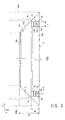
FIG. 3 is a plan view showing a structure of a module frame according to a preferred embodiment of the present invention. -
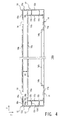
FIG. 4 is a side view showing a structure of a module frame according to a preferred embodiment of the present invention. -
FIG. 5 is a cross sectional diagram showing a structure of a module frame according to a preferred embodiment of the present invention. -
FIG. 6 is a front view of an outer appearance showing a structure of an elastic member according to a preferred embodiment of the present invention. -
FIG. 7 is a cross sectional diagram showing a structure of an elastic member according to a preferred embodiment of the present invention. -
FIG. 8 is a cross sectional diagram for explaining mounting of an elastic member to a module frame according to a preferred embodiment of the present invention. -
FIG. 9 is an enlarged cross sectional diagram for explaining mounting of an elastic member to a module frame according to a preferred embodiment of the present invention. -
FIG. 10 is a cross sectional diagram for explaining mounting of an elastic member and a photoelectric conversion panel to a module frame according to a preferred embodiment of the present invention. -
FIG. 11 is a perspective view for explaining an operation of a photoelectric conversion device according to a preferred embodiment of the present invention. -
FIG. 12 is a perspective view for explaining an operation of a photoelectric conversion device according to a preferred embodiment of the present invention. -
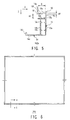
FIG. 13 is a plan view showing an alternative configuration of a structure of a module frame according to a preferred embodiment of the present invention. -
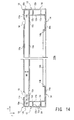
FIG. 14 is a side view showing an alternative configuration of a structure of a module frame according to a preferred embodiment of the present invention. - As shown in a front view of an outer appearance of
FIG. 1 and a back view of outer appearance ofFIG. 2 , a photoelectric conversion device according to a preferred embodiment of the present invention comprises amodule frame 100, anelastic member 200, and aphotoelectric conversion panel 300. Themodule frame 100 is formed such that a light-receiving surface, a side surface, and a back surface of four sides of the outer periphery of thephotoelectric conversion panel 300 are fitted with theelastic member 200 therebetween. - The
photoelectric conversion panel 300 has a structure similar to that of a typical solar cell panel, and is formed by layering, over a substrate, a transparent electrode, a photoelectric conversion unit, a backside electrode, and a sealing member. For the substrate, a transparent material such as glass and a resin is used. The transparent electrode is formed over the substrate, and, for the transparent electrode, there is preferably used a film containing one or a plurality of transparent conductive oxides (TCO) in which tin oxide (SnO2), zinc oxide (ZnO), indium tin oxide (ITO), or the like is doped with tin (Sn), antimony (Sb), fluorine (F), aluminum (Al), or the like. In particular, zinc oxide (ZnO) is preferable by virtue of its high light transmittance, low resistivity, and high plasma-resisting characteristic. The photoelectric conversion unit is formed over the transparent electrode. The photoelectric conversion unit is, for example, an amorphous silicon photoelectric conversion unit (a-Si unit), a microcrystalline silicon photoelectric conversion unit (µc-Si unit), or the like. Alternatively, the photoelectric conversion unit may have a structure in which a plurality of photoelectric conversion units are layered, such as a tandem-type structure or a triple-type structure. The backside electrode is formed over the photoelectric conversion unit, and preferably has a layered structure of a transparent conductive oxide (TCO) and a reflective metal. As the transparent conductive oxide (TCO), tin oxide (SnO2), zinc oxide (ZnO), indium tin oxide (ITO), or the like is used. As the reflective metal, a metal such as silver (Ag), aluminum (Al), or the like is used. The layered structure is sealed by the sealing member. For example, the backside electrode is covered with a filler and a back sheet. The sealing member is preferably made of a resin material such as EVA or polyimide. - The
photoelectric conversion panel 300 is not limited to such a structure, and any structure may be employed so long as themodule frame 100 and theelastic member 200 to be described below can be applied. - As shown in
FIGs. 1 and 2 , themodule frame 100 comprisesmodule frame members 100a - 100d. Themodule frame members 100a - 100d are combined to form the four sides of themodule frame 100. Themodule frame members 100a - 100d are formed in lengths necessary to support four sides of thephotoelectric conversion panel 300. Because themodule frame members 100a - 100d have similar structures, in the following, themodule frame member 100a is exemplified. However, when it is described that the structure is unique to themodule frame member 100a, such a structure is not applicable to other members. -
FIGs. 3 ,4 , and5 are a front view, a side view, and a cross sectional view of themodule frame member 100a.FIG. 3 is a front view viewing themodule frame member 100a from a Z direction ofFIG. 4. FIG. 4 is a side view viewing themodule frame member 100a from a Y direction ofFIG. 3 . InFIG. 4 , a hatching is applied to clearly show an end surface of themodule frame member 100a.FIG. 5 is a cross sectional diagram along a line A-A inFIG. 3 . - As shown in
FIGs. 3 ,4 , and5 , themodule frame member 100a is formed by combining apanel frame section 10, asupport section 12, and abottom surface section 14. Themodule frame member 100a is formed with a material having a mechanical strength sufficient to support thephotoelectric conversion panel 300 in the installed state. Themodule frame member 100a is preferably formed, for example, from a metal material such as aluminum, light-gauge steel frame, or the like, or a synthetic material such as a carbon resin. - The
panel frame section 10 is a section, in themodule frame member 100a, forming a frame to which theelastic member 200 and thephotoelectric conversion panel 300 are inserted. As shown inFIGs. 4 and5 , thepanel frame section 10 comprises a framefront surface section 10a, a frame backsurface section 10b, and a frameside surface section 10c. The framefront surface section 10a, the frame backsurface section 10b, and the frameside surface section 10c are combined in a U shape, and have a structure in which the framefront surface section 10a and the frame backsurface section 10b are connected by the frameside surface section 10c. The framefront surface section 10a and the frame backsurface section 10b are plate-shaped members, and, as shown in the plan view ofFIG. 3 , the framefront surface section 10a and the frame backsurface section 10b have a width W1 necessary for mechanically supporting thephotoelectric conversion panel 300. In addition, the framefront surface section 10a and the frame backsurface section 10b are placed to be parallel with a panel surface when thephotoelectric conversion panel 300 is placed along a length direction X of themodule frame member 100a. As shown inFIG. 5 , a distance H1 between the framefront surface section 10a and the frame backsurface section 10b is set to a size to allow theelastic member 200 and thephotoelectric conversion panel 300 to be fitted on thepanel frame section 10 without being loosened. The frameside surface section 10c connects the framefront surface section 10a and the frame backsurface section 10b at the outer periphery portion of thepanel frame section 10. As shown inFIG. 4 , thepanel frame section 10 is placed such that, when themodule frame 100 is formed, an inner surface of the U shape formed by the framefront surface section 10a, the frame backsurface section 10b, and the frameside surface section 10c faces the inner side of themodule frame 100. - In addition, as shown in
FIGs. 3 and4 , agroove 10e is formed on the framefront surface section 10a and the frame backsurface section 10b, to be fitted with aprotrusion 24 of theelastic member 200 to be described later. Thegroove 10e is formed in a line shape on the inner surfaces of the framefront surface section 10a and the frame backsurface section 10b placed to oppose each other, and along the length direction X of themodule frame member 100a. In the present embodiment, twogrooves 10e are formed on each of the framefront surface section 10a and the frame backsurface section 10b, in an opposing manner. - The
grooves 10e may be provided in any shape, size, position, or number which allows fitting of theprotrusion 24 of theelastic member 200. For example, as will be described later with reference toFIG. 9 , eachgroove 10e is preferably machined such that aninclination 10f on the side of a U-shaped opening of thepanel frame section 10 is larger than aninclination 10g at an opposite side of the opening. With such a configuration, theprotrusion 24 of theelastic member 200 can be easily fitted when theelastic member 200 is mounted to thepanel frame section 10, and theelastic member 200 is not easily detached from thepanel frame section 10 once theelastic member 200 is mounted. - As shown in
FIGs. 4 and5 , thesupport section 12 is a member which connects thepanel frame section 10 and thebottom surface section 14 in themodule frame member 100a. Thesupport section 12 supports thephotoelectric conversion panel 300 inserted into thepanel frame section 10. Thesupport section 12 comprises an outerside surface section 12a, an innerside surface section 12b, and aseparation member 12c. The outerside surface section 12a and the innerside surface section 12b are plate-shaped members, and connect the frame backsurface section 10b of thepanel frame section 10 and thebottom surface section 14 along the length direction X of themodule frame member 100a. The outerside surface section 12a and the innerside surface section 12b are placed such that, when themodule frame 100 is formed, the outerside surface section 12a serves as an outer frame positioned on an outer peripheral section of themodule frame 100 and the innerside surface section 12b serves as an inner frame positioned at an inner position in relation to the outerside surface section 12a. Theseparation member 12c is provided between the outerside surface section 12a and the innerside surface section 12b, and increases the mechanical strength by forming a hollow structure for thesupport section 12. - As shown in
FIGs. 4 and5 , adividing opening 12d which divides theseparation member 12c at an intermediate portion in a line shape is preferably formed in theseparation member 12c. The dividingopening 12d may simply be a through hole which penetrates through theseparation member 12c. With such a configuration, water entering the hollow section of thesupport section 12 can be discharged to the outside of themodule frame 100 through the dividingopening 12d and gaps or the like of the connection section of themodule frame members 100a - 100d. - As shown in
FIGs. 4 and5 , thebottom surface section 14 is a section which forms a base for fixing the photoelectric conversion device in an installation location. Thebottom surface section 14 comprises aflat plate section 14a. As shown inFIG. 3 , theflat plate section 14a has a width W2, and is placed to be parallel to the panel surface when thephotoelectric conversion panel 300 is placed along the length direction X of themodule frame member 100a. With this configuration, when the photoelectric conversion device is fixed at the installation location, thephotoelectric conversion panel 300 and thebottom surface section 14 can be installed such that an inclination of the panel surface of thephotoelectric conversion panel 300 fitted to the U-shaped portion of thepanel frame section 10 and an inclination of thebottom surface section 14 coincide with each other. In addition, as shown inFIG. 3 , the width W2 of theflat plate section 14a is preferably set wider than the width W of the framefront surface section 10a and the frame backsurface section 10b of thepanel frame section 10. With this configuration, themodule frame 100 can be mounted in a mechanically stable manner. - Alternatively, as shown in
FIGs. 4 and5 , a raisedsection 14b in which an edge of thebottom surface section 14 is raised along the length direction X of themodule frame member 100a may be provided. With the provision of the risensection 14b, it is possible to improve the mechanical strength of thebottom surface section 14. - As shown in
FIG. 3 , each of ends of themodule frame members 100a - 100d are machined to an end surface 16 (shown with hatching inFIG. 4 ) which is cut at 45° with respect to the length direction X and the width direction Y of themodule frame member 100a. The end surfaces 16 of themodule frame members 100a - 100d are connected opposing each other, to form therectangular module frame 100. The connection of the members is achieved by, for example, inserting L-shaped members into a hollow structure surrounded by the outerside surface section 12a, the innerside surface section 12b, and theseparation member 12c. - Next, a structure unique to the
module frame member 100a will be described. As shown inFIGs. 3 ,4 , and5 , acutout region 18 is provided near both ends in the length direction X. As shown inFIGs. 3 and5 , thecutout region 18 is a region where a part of the framefront surface section 10a and the frameside surface section 10c is cut out for a length L1 along the length direction X. The length L1 of thecutout region 18 is preferably set greater than or equal to 5 mm and less than or equal to 20 mm. In addition, a height H2 of thecutout region 18 is preferably set larger than a thickness of the framefront surface section 10a so that a part of the frameside surface section 10c is also cut out. For example, when the thickness of the framefront surface section 10a is greater than or equal to 1 mm and less than or equal to 5 mm, the height H2 of thecutout region 18 is preferably set larger than the thickness of the framefront surface section 10a in a range of greater than or equal to 1.5 mm and less than or equal to 10 mm. - In the present embodiment, the
cutout region 18 has a rectangular shape as viewed from the front, but the present invention is not limited to such a configuration. For example, thecutout region 18 may have a trapezoid shape as viewed from the front or may have a shape of a combination of a plurality of rectangles. - In addition, as shown in
FIGs. 3 ,4 , and5 , aback surface hole 18a is formed in the frame backsurface section 10b matching the position of thecutout region 18. As shown inFIG. 3 , theback surface hole 18a is preferably formed at a position overlapping thecutout region 18 as viewed from the front. By forming theback surface hole 18a at a position overlapping thecutout region 18, it is possible to open theback surface hole 18a from the opening of thecutout region 18, and to improve workability of themodule frame member 100a. In addition, theback surface hole 18a is preferably formed so that at least a part of theback surface hole 18a overlaps thegroove 10e. - In the present embodiment, the
back surface hole 18a has a circular cross section as viewed from the front, but the present invention is not limited to such a configuration. For example, theback surface hole 18a may have a cross section of a rectangular or triangular shape. In addition, in the case of the circular shape the size of theback surface hole 18a is preferably set to greater than or equal to 2 mm and less than or equal to the length L1. - Next, the
elastic member 200 will be described. As shown in a plan view ofFIG. 6 , theelastic member 200 has a rectangular outer appearance mounted within thepanel frame section 10 of themodule frame 100. Theelastic member 200 is preferably formed from a material having a lower modulus of elasticity than the material of themodule frame 100 and the material of the substrate of thephotoelectric conversion panel 300. For example, when themodule frame 100 is made of aluminum (having a modulus of elasticity of 7.03 x 10¹⁰ Pa) and the substrate of thephotoelectric conversion panel 300 is made of glass (having a modulus of elasticity of 7.16 x 10¹⁰ Pa), it is preferable to use an olefin-based thermoplastic elastomer. More specifically, it is preferable to use a material which includes at least one of synthesized (isoprene) rubber, styrene rubber, butadiene rubber, urethane rubber, fluororubber, butyl rubber, and silicone rubber. -
FIG. 7 is a diagram showing a cross sectional structure of theelastic member 200 along a line B-B ofFIG. 6 . Theelastic member 200 comprises, as basic members, an elastic memberfront surface section 20a, an elastic member backsurface section 20b, and an elastic memberside surface section 20c. The elastic memberfront surface section 20a and the elastic member backsurface section 20b are placed opposing each other, and the elastic memberfront surface section 20a and the elastic member backsurface section 20b are connected in a U shape by the elastic memberside surface section 20c. In theelastic member 200, a through hole or a slit may be formed in at least a part of the elastic memberfront surface section 20a, the elastic member backsurface section 20b, and the elastic memberside surface section 20c. With this configuration, even when water enters a gap between thephotoelectric conversion panel 300 and theelastic member 200, the water can be easily discharged to the outside. - As will be described later with reference to
FIG. 9 , a height H3 of the elastic memberfront surface section 20a and the elastic member backsurface section 20b is set to be equal to or less than a depth D of the U shape of thepanel frame section 10. As shown inFIG. 7 , on an end of the elastic member backsurface section 20b, aprotrusion 22a protruding toward an outer side and aprotrusion 22b protruding toward an inner side are provided. In addition, on an end of the elastic memberfront surface section 20a, aprotrusion 22c protruding toward the inner side is provided. Meanwhile, on the end of the elastic memberfront surface section 20a, no protrusion protruding toward the outer side is provided. Theprotrusion 22a is preferably provided to protrude in an approximate perpendicular direction with respect to the end of the elastic member backsurface section 20b. Theprotrusion 22b and theprotrusion 22c are preferably provided to gradually incline from a deeper part of the U shape of theelastic member 200 toward the outside. - As will be described later with reference to
FIG. 9 , an outer width W3 of theelastic member 200 is set slightly smaller than the height H1 of thepanel frame section 10. As shown inFIG. 7 , the line-shapedprotrusion 24 is formed on an outer wall surface of the elastic memberfront surface section 20a and the elastic member backsurface section 20b, along a length direction of theelastic member 200. Theprotrusion 24 is provided in a shape, size, position, and number to be fitted with thegroove 10e formed on the inner wall of thepanel frame section 10 when theelastic member 200 is mounted on thepanel frame section 10. In the present embodiment, twoprotrusions 24 having semicircular cross sections are provided on each of the outer wall surfaces of the elastic memberfront surface section 20a and the elastic member backsurface section 20b. - As will be described later with reference to
FIG. 10 , a width W4 of the inside of the U shape of theelastic member 200 is set slightly larger than a thickness T of thephotoelectric conversion panel 300. In addition, as shown inFIG. 7 ,protrusions 26 are formed on inner wall surfaces of the elastic memberfront surface section 20a and the elastic member backsurface section 20b, along the length direction of theelastic member 200. The shape, size, position, and number of theprotrusions 26 may be suitably changed, and, in the present embodiment, two crease-shapedprotrusions 26 protruding from the side of the opening of the U shape of theelastic member 200 toward the deeper part are provided on each of the inner wall surfaces of the elastic memberfront surface section 20a and the elastic member backsurface section 20b. - The photoelectric conversion device is formed by mounting the
elastic member 200 and thephotoelectric conversion panel 300 on themodule frame 100.FIGs. 8 and 9 show an example mounting of theelastic member 200 to themodule frame member 100a. Theelastic member 200 can be inserted into the othermodule frame members 100b - 100d in a similar manner. -
FIGs. 8 and 9 show cross sections along a line A-A of themodule frame member 100a shown inFIG. 3 .FIG. 9 is a diagram enlarging and showing a portion of thepanel frame section 10 in the cross sectional diagram ofFIG. 8 . - As shown in
FIGs. 8 and 9 , theelastic member 200 is inserted to thepanel frame section 10 of themodule frame 100. Because an outer width W3 of theelastic member 200 is set slightly smaller than the height H1 of thepanel frame section 10, theelastic member 200 is fitted to the U-shaped portion of thepanel frame section 10 by its elastic force. In addition, because the height H3 of theelastic member 200 is set to be equal to or smaller than the depth D of the U shape of thepanel frame section 10, theelastic member 200 can be completely inserted to thepanel frame section 10 by inserting theelastic member 200 until theprotrusion 22a provided at the end contacts thepanel frame section 10. - Moreover, as shown in
FIG. 9 , the line-shapedprotrusions 24 provided on the outer wall surfaces of the elastic memberfront surface section 20a and the elastic member backsurface section 20b of theelastic member 200 engage thegrooves 10e formed on the inner wall of thepanel frame section 10. With this configuration, theelastic member 200 can be inserted so that theelastic member 200 is not easily detached from thepanel frame section 10. Here, because theinclination 10f on the side of the entrance of the U shape is machined to be larger than theinclination 10g on the deeper part in thegroove 10e, theprotrusion 24 can be easily inserted along theinclination 10g and toward the deeper part of the U shape when theelastic member 200 is inserted into thepanel frame section 10, and theprotrusion 24 is not easily detached from thegroove 10e once theprotrusion 24 is inserted. -
FIG. 10 shows an example of theelastic member 200 and thephotoelectric conversion panel 300 mounted to themodule frame member 100a.FIG. 10 shows a cross section along a line A-A of themodule frame member 100a shown inFIG. 3 . Theelastic member 200 and thephotoelectric conversion panel 300 can be inserted for the othermodule frame members 100b - 100d in a similar manner. - As shown in
FIG. 10 , thephotoelectric conversion panel 300 is fitted to themodule frame member 100a in a state where theelastic member 200 is mounted. Because the width W4 of the inner side of the U shape of theelastic member 200 is slightly larger than the thickness T of thephotoelectric conversion panel 300, thephotoelectric conversion panel 300 is fitted to the U-shaped portion of theelastic member 200 by the elastic force of theelastic member 200. - Because the crease-shaped
protrusion 26 protruding from the side of the U-shaped opening of theelastic member 200 toward the deeper part is provided, when thephotoelectric conversion panel 300 is inserted into theelastic member 200, theprotrusion 26 is tilted in the insertion direction and can be easily inserted toward the deeper part of the U shape, and, once thephotoelectric conversion panel 300 is inserted, thephotoelectric conversion panel 300 is not easily detached, due to the elastic force of theprotrusion 26 and the frictional force on the surface. - In addition, because the
protrusion 22b and theprotrusion 22c which are gradually inclined from the deeper part of the U shape toward the outer side are provided on the ends of theelastic member 200, the insertedphotoelectric conversion panel 300 is subjected to a force to push toward the deeper part of the U shape by the elastic forces of theprotrusion 22b and theprotrusion 22c. With this configuration, it is possible to make it more difficult for thephotoelectric conversion panel 300 to be detached from theelastic member 200. - Next, with reference to partial cross sectional perspective views of
FIGs. 11 and12 , an operation of the photoelectric conversion device in the present embodiment will be described. InFIG. 11 , in order to clarify an explanation for a case where water adheres to the side of the light receiving surface (front surface) of thephotoelectric conversion panel 300, a part of thegroove 10e of the framefront surface section 10a and themodule frame 100 is shown with a broken line. In addition, inFIG. 12 , in order to clarify an explanation for a case where water adheres to the back surface side of thephotoelectric conversion panel 300,FIG. 12 is shown as an inside opened-up view to clearly show thegroove 10e of the frame backsurface section 10b of themodule frame 100. - The photoelectric conversion device is installed in an inclined manner, with the
module frame member 100a at the lower side. When water adheres to thephotoelectric conversion panel 300 due to rain or the like in such an installation state, as shown by a wide solid line arrow ofFIG. 11 , the water flowing along the surface of thephotoelectric conversion panel 300 along the inclination of the installation accumulates at the end of thepanel frame section 10 of themodule frame member 100a, is transferred and flows along the length direction X of themodule frame member 100a due to the slight inclination of themodule frame 100, reaches one of thecutout regions 18 provided on the ends, and is discharged to the outside of themodule frame member 100a through thecutout region 18. - Here, because no protrusion protruding toward the outer side is provided on the end of the elastic member
front surface section 20a of theelastic member 200, the water flowing along the end of thepanel frame section 10 of themodule frame member 100a can flow into thecutout region 18 without being blocked by a protrusion. Therefore, the water which has flowed along the end of thepanel frame section 10 can be quickly and reliably discharged to the outside of themodule frame 100. As can be understood, it is sufficient that the protrusion protruding toward the outer side is not provided at least in a part of the region of the end of the elastic memberfront surface section 20a; in particular, in a region overlapping thecutout region 18. - Even if water enters from the gap between the
elastic member 200 and themodule frame member 100a to the inside of the U shape of thepanel frame section 10, as shown by the wide broken line arrow ofFIG. 11 , the water is stopped at thegroove 10e of the framefront surface section 10a to which theprotrusion 24 is fitted, reaches one of thecutout regions 18 along thegroove 10e of the framefront surface section 10a, and is discharged to the outside of themodule frame member 100a through thecutout region 18. In this manner, the water entering the gap between theelastic member 200 and the framefront surface section 10a can be quickly and reliably discharged to the outside of themodule frame 100. - On the other hand, when water adheres to the back surface of the
photoelectric conversion panel 300, as shown by a narrow broken line arrow ofFIG. 11 , the water flows down along the back surface of thephotoelectric conversion panel 300 along the inclination of installation. Because theprotrusion 22a protruding toward the outer side is not provided on the end of the elastic member backsurface section 20b, the water flows along the edge of theprotrusion 22a of theelastic member 200 and down to thebottom surface section 14. In addition, because of theprotrusion 22a, water tends to not enter the gap between theelastic member 200 and the frame backsurface section 10b of themodule frame member 100a. - In addition, even when water enters from the gap between the
elastic member 200 and the frame backsurface section 10b to the inside of the U shape of thepanel frame section 10, as shown by a wide solid line arrow ofFIG. 12 , the water is stopped at thechannel 10e of the frame backsurface section 10b to which theprotrusion 24 is fitted; reaches, along thegroove 10e of the frame backsurface section 10b, theback surface hole 18a formed in thecutout region 18; and flows into the hollow structure of thesupport section 12 of themodule frame member 100a through theback surface hole 18a. Then, the water reaches the end of themodule frame member 100a through the hollow structure, and is discharged to the outside through the gap of a connection section between themodule frame member 100a and themodule frame member - As described, according to the photoelectric conversion device of the present embodiment, even when the
photoelectric conversion panel 300 is exposed to rain or the like, the water can be quickly and reliably discharged to the outside of the device. Therefore, the degradation of thephotoelectric conversion panel 300 can be inhibited, and the reliability of the photoelectric conversion device can be improved. - In the present embodiment, the
cutout region 18 and theback surface hole 18a are formed on both ends of themodule frame member 100a, but it is sufficient that at least one of each of thecutout region 18 and theback surface hole 18a is provided. By forming thecutout region 18 and theback surface hole 18a on both ends of themodule frame member 100a, there is an advantage that the water can be reliably discharged from one of the ends according to the inclination of the photoelectric conversion device. - In addition, in the present embodiment, the
cutout region 18 and theback surface hole 18a are formed only on themodule frame member 100a, but alternatively, thecutout region 18 and theback surface hole 18a may be provided similarly on the othermodule frame members 100b - 100d. When thecutout region 18 and theback surface hole 18a are provided only on themodule frame member 100a, it is preferable to install the device such that themodule frame member 100a is positioned at a lower side, as in the present embodiment, in order to reliably discharge water. In addition, when themodule frame 100 has a rectangular shape, the device may be installed with either the long side or the short side positioned at the lower side. In this case, however, it is preferable to provide thecutout region 18 and theback surface hole 18a at least on the module frame member positioned at the lower side. - Alternatively, as shown in a plan view of
FIG. 13 and a cross sectional view ofFIG. 14 , at least a part of an outerside surface section 12a forming a corner of thesupport section 12 of themodule frame member 100a may preferably be cut out to provide anend cutout region 30. Similarly, theend cutout region 30 may be provided as necessary on the module frames 100b - 100d, rather than on themodule frame member 100a. With theend cutout region 30 provided, as described above, the water flowing from the back surface of thephotoelectric conversion panel 300 into the hollow structure of thesupport section 12 of themodule frame member 100a can be quickly and reliably discharged to the outside through theend cutout region 30. - 10 PANEL FRAME SECTION; 10a FRAME FRONT SURFACE SECTION; 10b FRAME BACK SURFACE SECTION; 10c FRAME SIDE SURFACE SECTION; 10e GROOVE; 10f INCLINATION; 10g INCLINATION; 12 SUPPORT SECTION; 12a OUTER SIDE SURFACE SECTION; 12b INNER SIDE SURFACE SECTION; 12c SEPARATION MEMBER; 12d DIVIDING OPENING; 14 BOTTOM SURFACE SECTION; 14a FLAT PLATE SECTION; 14b RISEN SECTION; 16 END SURFACE; 18 CUTOUT REGION; 18a BACK SURFACE HOLE; 20a ELASTIC MEMBER FRONT SURFACE SECTION; 20b ELASTIC MEMBER BACK SURFACE SECTION; 20c ELASTIC MEMBER SIDE SURFACE SECTION; 22a PROTRUSION; 22b PROTRUSION; 22c PROTRUSION; 24 PROTRUSION; 26 PROTRUSION; 30 END CUTOUT REGION; 100 MODULE FRAME; 100a - 100d MODULE FRAME MEMBER; 200 ELASTIC MEMBER; 300 PHOTOELECTRIC CONVERSION PANEL
Claims (5)
- A photoelectric conversion device comprising:a photoelectric conversion panel; anda module frame which supports the photoelectric conversion panel, whereinthe module frame comprises a U-shaped panel frame section having a frame front surface section, a frame side surface section, and a frame back surface section provided to surround a front surface, a side surface, and a back surface, respectively, of an end side region of the photoelectric conversion panel,a cutout region is formed in the frame front surface section from an end of the U shape to the frame side surface section, anda back surface hole penetrating through the frame back surface section is formed in the frame back surface section.
- The photoelectric conversion device according to Claim 1, wherein
the cutout region and the back surface hole are formed in a module frame member, among module frame members forming the module frame, which supports a lower side of the photoelectric conversion panel. - The photoelectric conversion device according to Claim 1 or 2, wherein
the back surface hole is formed in a position overlapping the cutout region viewed form a side of the frame front surface section. - The photoelectric conversion device according to any one of Claims 1 - 3, wherein
an end cutout region connecting the back surface hole and an outside of the module frame is formed at a corner of the module frame. - The photoelectric conversion device according to any one of Claims 1 - 4, wherein
the frame back surface section comprises a groove formed in a line shape along a direction of a side of the photoelectric conversion panel, and
the back surface hole is formed at a position overlapping at least a part of the line-shaped groove.
Applications Claiming Priority (2)
| Application Number | Priority Date | Filing Date | Title |
|---|---|---|---|
| JP2010012042A JP2011149219A (en) | 2010-01-22 | 2010-01-22 | Photoelectric conversion device |
| PCT/JP2011/050343 WO2011089954A1 (en) | 2010-01-22 | 2011-01-12 | Photoelectric conversion device |
Publications (2)
| Publication Number | Publication Date |
|---|---|
| EP2527557A1 true EP2527557A1 (en) | 2012-11-28 |
| EP2527557A4 EP2527557A4 (en) | 2015-08-26 |
Family
ID=44306756
Family Applications (1)
| Application Number | Title | Priority Date | Filing Date |
|---|---|---|---|
| EP11734561.1A Withdrawn EP2527557A4 (en) | 2010-01-22 | 2011-01-12 | Photoelectric conversion device |
Country Status (5)
| Country | Link |
|---|---|
| US (1) | US20120291858A1 (en) |
| EP (1) | EP2527557A4 (en) |
| JP (1) | JP2011149219A (en) |
| CN (1) | CN202945754U (en) |
| WO (1) | WO2011089954A1 (en) |
Families Citing this family (18)
| Publication number | Priority date | Publication date | Assignee | Title |
|---|---|---|---|---|
| ITRM20110435A1 (en) * | 2011-08-10 | 2013-02-11 | Stefano Luigi Di | FORCED AIR CIRCULATION EQUIPMENT FOR COOLING PHOTOVOLTAIC SOLAR PANELS IN OPERATION |
| TWM423229U (en) * | 2011-10-07 | 2012-02-21 | Hulk Energy Technology Co Ltd | Frame structure of solar energy module |
| CN103187464A (en) * | 2011-12-29 | 2013-07-03 | 杜邦太阳能有限公司 | Solar module and elastic inner frame thereof |
| CN103362258B (en) * | 2012-03-28 | 2015-12-02 | 中电电气(上海)太阳能科技有限公司 | Quick mounting type solar energy roof tile component |
| US20140182661A1 (en) * | 2012-12-28 | 2014-07-03 | Sunpower Corporation | Photovoltaic module frame with improved bondability |
| USD772800S1 (en) * | 2014-02-25 | 2016-11-29 | Derek Djeu | Solar cell backing plate |
| CN103840761A (en) * | 2014-03-18 | 2014-06-04 | 连云港神舟新能源有限公司 | Easily-drained and self-cleaning solar battery assembly framework |
| JP2015195663A (en) * | 2014-03-31 | 2015-11-05 | パナソニックIpマネジメント株式会社 | Solar cell module |
| TWI505631B (en) * | 2014-06-20 | 2015-10-21 | Neo Solar Power Corp | Frame of solar module |
| JP6453074B2 (en) * | 2014-12-24 | 2019-01-16 | シャープ株式会社 | Solar cell module |
| JP6497933B2 (en) * | 2014-12-24 | 2019-04-10 | シャープ株式会社 | Solar cell module |
| JP6511269B2 (en) * | 2015-01-13 | 2019-05-15 | 株式会社カネカ | Roof structure |
| JP6612573B2 (en) * | 2015-09-29 | 2019-11-27 | 積水化学工業株式会社 | Solar panel housing and water tap automatic opening and closing device |
| CN106911299A (en) * | 2017-02-23 | 2017-06-30 | 迈贝特(厦门)新能源有限公司 | A kind of solar panels package assembly and fixed border |
| JP6605679B1 (en) * | 2018-09-10 | 2019-11-13 | 連豐 薛 | Waterproof connection structure |
| EP3748842A4 (en) | 2018-12-06 | 2021-07-28 | Shanghai Ja Solar Technology Co., Ltd. | DOUBLE GLASS PHOTOVOLTAIC ARRANGEMENT |
| WO2021118497A1 (en) * | 2019-12-11 | 2021-06-17 | Borcelik Celik San. Tic. A.S. | A frame |
| TWI827509B (en) * | 2023-04-25 | 2023-12-21 | 龍佳欣實業股份有限公司 | Optoelectronic panel packaging structure and method thereof |
Family Cites Families (12)
| Publication number | Priority date | Publication date | Assignee | Title |
|---|---|---|---|---|
| JPS60103855U (en) * | 1983-12-19 | 1985-07-15 | 京セラ株式会社 | solar cell module |
| JPH0310559U (en) * | 1989-06-16 | 1991-01-31 | ||
| US5484626A (en) | 1992-04-06 | 1996-01-16 | Shipley Company L.L.C. | Methods and apparatus for maintaining electroless plating solutions |
| JPH086402B2 (en) * | 1992-10-28 | 1996-01-24 | 元旦ビューティ工業株式会社 | Roof structure using solar panels |
| JPH08148710A (en) * | 1994-11-17 | 1996-06-07 | Daido Hoxan Inc | Method of fitting metal frame to outer edge of solar cell module panel |
| JP3305945B2 (en) * | 1996-02-27 | 2002-07-24 | 積水化学工業株式会社 | Solar cell module, solar cell module unit, mounting method thereof, and roof mounting these |
| JPH11325610A (en) * | 1998-05-12 | 1999-11-26 | Mitsubishi Electric Corp | Solar energy utilization equipment |
| JP3748370B2 (en) | 2000-09-11 | 2006-02-22 | シャープ株式会社 | Solar cell module |
| EP1860705B1 (en) | 2005-03-18 | 2016-10-26 | Kyocera Corporation | Solar cell module and solar cell array |
| JP4563239B2 (en) * | 2005-03-31 | 2010-10-13 | 三菱重工業株式会社 | Solar panel |
| WO2008041298A1 (en) * | 2006-09-29 | 2008-04-10 | Mitsubishi Heavy Industries, Ltd. | Solar cell panel |
| JP5235395B2 (en) * | 2007-12-07 | 2013-07-10 | 三菱電機株式会社 | Solar cell module |
-
2010
- 2010-01-22 JP JP2010012042A patent/JP2011149219A/en active Pending
-
2011
- 2011-01-12 CN CN2011900002863U patent/CN202945754U/en not_active Expired - Fee Related
- 2011-01-12 EP EP11734561.1A patent/EP2527557A4/en not_active Withdrawn
- 2011-01-12 WO PCT/JP2011/050343 patent/WO2011089954A1/en not_active Ceased
-
2012
- 2012-07-18 US US13/551,842 patent/US20120291858A1/en not_active Abandoned
Non-Patent Citations (1)
| Title |
|---|
| See references of WO2011089954A1 * |
Also Published As
| Publication number | Publication date |
|---|---|
| JP2011149219A (en) | 2011-08-04 |
| CN202945754U (en) | 2013-05-22 |
| WO2011089954A1 (en) | 2011-07-28 |
| US20120291858A1 (en) | 2012-11-22 |
| EP2527557A4 (en) | 2015-08-26 |
Similar Documents
| Publication | Publication Date | Title |
|---|---|---|
| US20120291858A1 (en) | Photoelectric conversion device | |
| CN101675529B (en) | Solar battery module device | |
| US11522089B2 (en) | Double-glass photovoltaic assembly | |
| KR101050010B1 (en) | Solar panel | |
| US6242685B1 (en) | Structure and method of installing photovoltaic module | |
| US9947818B2 (en) | Solar cell module | |
| KR101091372B1 (en) | Solar cell apparatus | |
| US20120055550A1 (en) | Solar module with light-transmissive edge seal | |
| EP2312647A1 (en) | Solar cell module | |
| EP2772946A1 (en) | Solar cell module and solar cell array | |
| EP2423971A1 (en) | Solar battery module | |
| JP2016089620A (en) | Solar array | |
| JP5159832B2 (en) | Solar cell module device | |
| EP2341554A2 (en) | Solar panel tile structure and combination thereof | |
| CN119093844A (en) | Photovoltaic frames and photovoltaic modules | |
| JP4127610B2 (en) | Solar cell module | |
| US8859881B2 (en) | Solar battery module | |
| JP2011238761A (en) | Solar cell module | |
| CN113756518A (en) | Photovoltaic tile assembly and photovoltaic roof | |
| CN215907209U (en) | Photovoltaic tile assembly and photovoltaic roof | |
| KR20110074304A (en) | Solar power unit | |
| JP5590898B2 (en) | Solar cell module and solar cell system | |
| CN224021671U (en) | Photovoltaic frame device and photovoltaic module | |
| JPWO2013058190A1 (en) | Frame for solar cell panel and solar cell module using the same | |
| CN222736084U (en) | Photovoltaic panel connection system |
Legal Events
| Date | Code | Title | Description |
|---|---|---|---|
| PUAI | Public reference made under article 153(3) epc to a published international application that has entered the european phase |
Free format text: ORIGINAL CODE: 0009012 |
|
| 17P | Request for examination filed |
Effective date: 20120718 |
|
| AK | Designated contracting states |
Kind code of ref document: A1 Designated state(s): AL AT BE BG CH CY CZ DE DK EE ES FI FR GB GR HR HU IE IS IT LI LT LU LV MC MK MT NL NO PL PT RO RS SE SI SK SM TR |
|
| DAX | Request for extension of the european patent (deleted) | ||
| RA4 | Supplementary search report drawn up and despatched (corrected) |
Effective date: 20150723 |
|
| RIC1 | Information provided on ipc code assigned before grant |
Ipc: E04D 13/18 20140101AFI20150717BHEP Ipc: H02S 20/00 20140101ALI20150717BHEP Ipc: F24J 2/52 20060101ALI20150717BHEP |
|
| RAP1 | Party data changed (applicant data changed or rights of an application transferred) |
Owner name: PANASONIC INTELLECTUAL PROPERTY MANAGEMENT CO., LT |
|
| STAA | Information on the status of an ep patent application or granted ep patent |
Free format text: STATUS: THE APPLICATION HAS BEEN WITHDRAWN |
|
| 18W | Application withdrawn |
Effective date: 20151209 |