EP2527524A1 - Rotary-drum laundry dryer - Google Patents
Rotary-drum laundry dryer Download PDFInfo
- Publication number
- EP2527524A1 EP2527524A1 EP11167968A EP11167968A EP2527524A1 EP 2527524 A1 EP2527524 A1 EP 2527524A1 EP 11167968 A EP11167968 A EP 11167968A EP 11167968 A EP11167968 A EP 11167968A EP 2527524 A1 EP2527524 A1 EP 2527524A1
- Authority
- EP
- European Patent Office
- Prior art keywords
- air
- drum
- structured
- socle
- supporting base
- Prior art date
- Legal status (The legal status is an assumption and is not a legal conclusion. Google has not performed a legal analysis and makes no representation as to the accuracy of the status listed.)
- Granted
Links
- 230000003134 recirculating effect Effects 0.000 claims abstract description 80
- 230000000284 resting effect Effects 0.000 claims abstract description 11
- 238000009833 condensation Methods 0.000 claims abstract description 6
- 230000005494 condensation Effects 0.000 claims abstract description 6
- 239000003507 refrigerant Substances 0.000 claims description 63
- 238000010438 heat treatment Methods 0.000 claims description 9
- 238000001816 cooling Methods 0.000 claims description 6
- 230000002093 peripheral effect Effects 0.000 claims description 5
- 239000000463 material Substances 0.000 description 3
- 238000001035 drying Methods 0.000 description 2
- 238000001746 injection moulding Methods 0.000 description 2
- 230000006978 adaptation Effects 0.000 description 1
- 230000004323 axial length Effects 0.000 description 1
- 230000000295 complement effect Effects 0.000 description 1
- 238000006073 displacement reaction Methods 0.000 description 1
- 230000005611 electricity Effects 0.000 description 1
- 238000012986 modification Methods 0.000 description 1
- 230000004048 modification Effects 0.000 description 1
Images



Classifications
-
- D—TEXTILES; PAPER
- D06—TREATMENT OF TEXTILES OR THE LIKE; LAUNDERING; FLEXIBLE MATERIALS NOT OTHERWISE PROVIDED FOR
- D06F—LAUNDERING, DRYING, IRONING, PRESSING OR FOLDING TEXTILE ARTICLES
- D06F58/00—Domestic laundry dryers
- D06F58/20—General details of domestic laundry dryers
Definitions
- the present invention relates to a rotary-drum laundry dryer.
- the present invention relates to a rotary-drum home laundry dryer, to which the following description refers purely by way of example without implying any loss of generality.
- today's rotary-drum home laundry dryers comprise: a substantially parallelepiped-shaped outer boxlike casing structured for resting on the floor; a substantially cylindrical revolving drum structured for housing the laundry to be dried, and which is housed in axially rotating manner inside the casing to rotate about its horizontally-oriented longitudinal axis, directly facing a laundry loading/unloading opening formed in the front wall of the casing; a door hinged to the front wall of the casing to rotate to and from a closing position in which the door rests completely against the front wall of the casing to close the laundry loading/unloading opening and airtight seal the revolving drum; and an electric motor assembly structured for driving into rotation the revolving drum about its longitudinal axis inside the casing.
- Home laundry dryers of the above type are also provided with an open-circuit or closed-circuit, hot-air generator which is structured to circulate inside the revolving drum a stream of hot air having a low moisture content, and which flows through the revolving drum and over the laundry inside the drum to rapidly dry the laundry; and with an electronic central control unit which controls both the motor assembly and the hot-air generator to perform one of the user-selectable drying cycles stored in the same central control unit.
- the hot-air generator is usually a closed-circuit, heat-pump type, hot-air generator that comprises: an air recirculating conduit having its two ends connected to the revolving drum, on opposite sides of the latter; an electric centrifugal fan located along the air recirculating conduit to produce, inside the latter, an airflow which flows through the revolving drum; and finally a heat-pump assembly having its two heat exchangers located one after the other, along the air recirculating conduit.
- EP-2034084 discloses a heat-pump type, rotary-drum home laundry dryer wherein the electric centrifugal fan is located on the back of a lower supporting base or socle forming the floor-resting portion of the appliance casing. More specifically, a central section of the air recirculating conduit extends across the lower supporting base or socle, and the centrifugal fan is located on the back of the aforesaid lower supporting base or socle, at the end-opening of the central section of the air recirculating conduit, so as to protrude outside of said base or socle.
- Aim of the present invention is to simplify the structure of today's laundry dryers, so to simplify the assembly and/or replacement of the centrifugal fan.
- a rotary-drum laundry dryer comprising a revolving drum structured for housing the laundry to be dried, a hot-air generator structured to circulate a stream of hot air through said revolving drum, and a lower supporting base or socle which is structured for resting on the floor and for housing at least part of the hot-air generator;
- the hot-air generator in turn comprising: an air recirculating conduit having its two ends connected to the revolving drum; air circulating means which are located along the air recirculating conduit and are structured to produce, inside the air recirculating conduit, an airflow which flows through the revolving drum and over the laundry inside the drum; and at least one heat exchanger located along the air recirculating conduit and structured to cool the moist air arriving from the rotatable drum so to cause the condensation of the surplus moisture inside the airflow; a section of the air recirculating conduit extending across the lower supporting base or socle, and being structured so as to house said at least one heat exchanger of
- the rotary-drum laundry dryer is characterized in that the lower supporting base or socle comprises a lower half-shell structured for resting on the floor, and an upper half-shell stacked up on top of, and rigidly coupled to said lower half-shell; said lower half-shell and upper half-shell being shaped so as to form, when coupled to one another, said section of the air recirculating conduit which houses said at least one heat exchanger of the hot-air generator.
- the rotary-drum laundry dryer is characterized in that the end-opening of said central of the air recirculating conduit is delimited/formed by the lower half-shell and by the upper half-shell; and in that said intake manifold is jammed in between said lower and upper half-shells, at the end-opening of said central of the air recirculating conduit.
- the rotary-drum laundry dryer is characterized in that the impeller housing comprises a first portion directly associated to said lower supporting base or socle, and a second portion structured/shaped for being coupled in a rigid and stable, though easily releasable, manner to the first portion of the impeller housing to close said first portion and cover the impeller.
- the rotary-drum laundry dryer is characterized in that the first portion of the impeller housing is realized in one piece with said lower supporting base or socle, and in that second portion of the impeller housing comprises a substantially basin-shaped cover which is fixed in a rigid and stable, though easily releasable, manner to the part of said lower supporting base or socle forming the first portion of the impeller housing, so as to close the first portion of the impeller housing and completely cover said impeller.
- the rotary-drum laundry dryer is characterized in that the first portion of the impeller housing is partly realized in one piece with the lower half-shell and partly in one piece with the upper half-shell.
- the rotary-drum laundry dryer is characterized in that said intake manifold consists in a substantially frustoconical sleeve.
- the rotary-drum laundry dryer is characterized in that said frustoconical sleeve is provided, all-around the larger mouth, with an outwards projecting peripheral flange which is structured to fit into two corresponding coplanar grooves realized one in the lower half-shell, and the other in the upper half-shell.
- Rotary-drum laundry dryer according to any one of the foregoing claims, characterized in that impeller of the air circulating means is rigidly fitted to the axial end of a drive shaft extending through said intake manifold.
- the rotary-drum laundry dryer is characterized by also comprising an electric motor assembly which is mechanically connected to the revolving drum for rotating said drum about its longitudinal axis; said electric motor assembly being fixed on said lower supporting base or socle so that an axial end of the drive shaft of said electric motor assembly sticks out of the lower supporting base or socle, through said intake manifold, to support and drive into rotation said impeller.
- the rotary-drum laundry dryer is characterized by also comprising an upper boxlike cabinet which is rigidly fixed to the top of the lower supporting base or socle and is structured so to house the revolving drum.
- the rotary-drum laundry dryer is characterized in that the longitudinal axis of the revolving drum is substantially horizontally-oriented, and in that the revolving drum rests on a number of supporting rollers which are arranged substantially at the two axial ends of the revolving drum, and are fixed in free revolving manner directly to the top of said lower supporting base or socle.
- the rotary-drum laundry dryer is characterized in that the supporting rollers are fixed in free revolving manner directly to the upper half-shell of the lower supporting base or socle.
- the rotary-drum laundry dryer is characterized in that the hot-air generator is a heat-pump type, hot-air generator which comprises: a first air/refrigerant heat exchanger which is located inside said section of the air recirculating conduit, and is structured for rapidly cooling down the airflow arriving from the revolving drum to condense and restrain the surplus moisture in the airflow; a second air/refrigerant heat exchanger which is located inside said section of the air recirculating conduit, downstream of the first air/refrigerant heat exchanger, and which is structured for rapidly heating the airflow arriving from the first air/refrigerant heat exchanger and directed back to the revolving drum; a refrigerant compressing device which is interposed between the refrigerant-outlet of the first air/refrigerant heat exchanger and the refrigerant-inlet of the second air/refrigerant heat exchanger, and which is structured for compressing the gaseous-state refrigerant directed
- the rotary-drum laundry dryer is characterized in that the lower half-shell and the upper half-shell are both realized in plastic material preferably via an injection molding process.
- a rotary-drum laundry dryer comprising a revolving drum structured for housing the laundry to be dried, a hot-air generator structured to circulate a stream of hot air through said revolving drum, and a lower supporting base or socle which is structured for resting on the floor and for housing at least part of the hot-air generator;
- the hot-air generator in turn comprising: an air recirculating conduit having its two ends connected to the revolving drum; air circulating means which are located along the air recirculating conduit and are structured to produce, inside the air recirculating conduit, an airflow which flows through the revolving drum and over the laundry inside the drum; and at least one heat exchanger located along the air recirculating conduit and structured to cool the moist air arriving from the rotatable drum so to cause the condensation of the surplus moisture inside the airflow; a section of the air recirculating conduit extending across the lower supporting base or socle, and being structured so as to house said at least one heat exchanger of the hot-air
- the rotary-drum laundry dryer is characterized in that the air circulating means additionally comprises an impeller housing which communicates with the end-opening of said section of the air recirculating conduit, and an impeller which is housed in axially rotating manner inside the impeller housing to generate said airflow; the intake manifold extending within the impeller housing from the end-opening of said central of the air recirculating conduit, and towards the impeller.
- the rotary-drum laundry dryer is characterized in that the impeller housing comprises a first portion directly associated to said lower supporting base or socle, and a second portion structured/shaped for being coupled in a rigid and stable, though easily releasable, manner to the first portion of the impeller housing to close said first portion and cover the impeller.
- the rotary-drum laundry dryer is characterized in that the first portion of the impeller housing is realized in one piece with said lower supporting base or socle, and in that second portion of the impeller housing comprises a substantially basin-shaped cover which is fixed in a rigid and stable, though easily releasable, manner to the part of said lower supporting base or socle forming the first portion of the impeller housing, so as to close the first portion of the impeller housing and completely cover said impeller.
- the rotary-drum laundry dryer is characterized in that the lower half-shell and upper half-shell are shaped so as to form, when coupled to one another, said first portion of the impeller housing.
- the rotary-drum laundry dryer is characterized in that said air circulating means are located outside said lower supporting base or socle.
- the rotary-drum laundry dryer is characterized in that said intake manifold consists in a substantially frustoconical sleeve.
- the rotary-drum laundry dryer is characterized in that said frustoconical sleeve is provided, all-around the larger mouth, with an outwards projecting peripheral flange which is structured to fit into two corresponding coplanar grooves realized one in the lower half-shell, and the other in the upper half-shell.
- the rotary-drum laundry dryer is characterized in that the impeller of the air circulating means is rigidly fitted to the axial end of a drive shaft extending through said intake manifold.
- the rotary-drum laundry dryer is characterized by also comprising an electric motor assembly which is mechanically connected to the revolving drum for rotating said drum about its longitudinal axis; said electric motor assembly being fixed on said lower supporting base or socle so that an axial end of the drive shaft of said electric motor assembly sticks out of the lower supporting base or socle, through said intake manifold, to support and drive into rotation said impeller.
- the rotary-drum laundry dryer is characterized by also comprising an upper boxlike cabinet which is rigidly fixed to the top of the lower supporting base or socle and is structured so to house the revolving drum.
- the rotary-drum laundry dryer is characterized in that the longitudinal axis of the revolving drum is substantially horizontally-oriented, and in that the revolving drum rests on a number of supporting rollers which are arranged substantially at the two axial ends of the revolving drum, and are fixed in free revolving manner directly to the top of said lower supporting base or socle.
- the rotary-drum laundry dryer is characterized in that the supporting rollers are fixed in free revolving manner directly to the upper half-shell of the lower supporting base or socle.
- the rotary-drum laundry dryer is characterized in that the hot-air generator is a heat-pump type, hot-air generator which comprises: a first air/refrigerant heat exchanger which is located inside said section of the air recirculating conduit, and is structured for rapidly cooling down the airflow arriving from the revolving drum to condense and restrain the surplus moisture in the airflow; a second air/refrigerant heat exchanger which is located inside said section of the air recirculating conduit, downstream of the first air/refrigerant heat exchanger, and which is structured for rapidly heating the airflow arriving from the first air/refrigerant heat exchanger and directed back to the revolving drum; a refrigerant compressing device which is interposed between the refrigerant-outlet of the first air/refrigerant heat exchanger and the refrigerant-inlet of the second air/refrigerant heat exchanger, and which is structured for compressing the gaseous-state refrigerant directed
- number 1 indicates as a whole a preferably household, rotary-drum laundry dryer which comprises:
- the rotary-drum laundry dryer 1 additionally comprises an electric motor 5 which is mechanically connected to the revolving drum 3 for driving into rotation the drum 3 about its longitudinal axis; a closed-circuit, hot-air generator 6 which is structured to circulate through the revolving drum 3 a stream of hot air having a low moisture level, and which flows over and rapidly dries the laundry located inside drum 3; and finally an electronic central control unit 7 which controls both the electric motor 5 and the hot-air generator 6 to perform one of the user-selectable drying cycles preferably, though not necessarily, stored in the same central control unit 7.
- the outer boxlike casing 2 comprises a substantially parallelepiped-shaped lower supporting base or socle 9 which is structured for resting on the floor and for housing at least part of the hot-air generator 6; and a substantially parallelepiped-shaped upper boxlike cabinet 10 which is rigidly fixed to the top of the lower supporting base or socle 9 and it is structured so as to house the revolving drum 3.
- the revolving drum 3 preferably extends inside the boxlike cabinet 10 coaxial to a substantially horizontally-oriented longitudinal reference axis L, and rests on a number of substantially horizontally-oriented, front and rear idle supporting rollers 11 which are located in pairs substantially at the two axial ends of the revolving drum 3, and are fixed in free revolving manner to the casing 2 so as to allow the revolving drum 3 to freely rotate about its reference axis L inside the boxlike cabinet 10.
- front and rear idle supporting rollers 11 are preferably fixed in free revolving manner directly to the top of the lower supporting base or socle 9.
- the laundry loading/unloading opening of casing 2 is therefore realized in the front wall of the upper boxlike cabinet 10, and the porthole door 4 is hinged to the front wall of the aforesaid upper boxlike cabinet 10.
- the lower supporting base or socle 9 is also preferably structured so to directly support the electric motor 5.
- the closed-circuit, hot-air generator 6 instead preferably comprises of a heat-pump type, hot-air generator 6 which is structured for gradually drawing air from revolving drum 3; rapidly cooling down the air arriving from revolving drum 3 so to extract and retain the surplus moisture in the air drawn from revolving drum 3; rapidly heating the dehumidified air to a predetermined temperature, normally higher than the temperature of the air from revolving drum 3; and finally feeding the heated, dehumidified air back into the revolving drum 3, where it flows over the laundry inside the drum to rapidly dry said laundry.
- a heat-pump type, hot-air generator 6 which is structured for gradually drawing air from revolving drum 3; rapidly cooling down the air arriving from revolving drum 3 so to extract and retain the surplus moisture in the air drawn from revolving drum 3; rapidly heating the dehumidified air to a predetermined temperature, normally higher than the temperature of the air from revolving drum 3; and finally feeding the heated, dehumidified air back into
- hot-air generator 6 provides for continually dehumidifying and heating the air circulating inside revolving drum 3 to rapidly dry the laundry inside the drum, and basically comprises:
- a central/intermediate section of the air recirculating conduit 12 extends in pass-through manner across the lower supporting base or socle 9, and the centrifugal fan 13 is located outside the lower supporting base or socle 9, at the end-opening of the central section of the air recirculating conduit 12, so to directly communicate with, i.e. be fluidly connected to, the end-opening of the aforesaid central section of the air recirculating conduit 12.
- the central section of the air recirculating conduit 12 is preferably substantially horizontally-oriented inside the lower supporting base or socle 9.
- the centrifugal fan 13 is instead preferably located on the back of the lower supporting base or socle 9, and comprises an outer housing 15 which is located outside of the lower supporting base or socle 9, at the end-opening of the aforesaid central section of the air recirculating conduit 12, so to directly communicate with, i.e. be fluidly connected to, said end-opening of the central section of the air recirculating conduit 12, and also with the inside of revolving drum 3; and an impeller 16 which is housed in axially rotating manner inside the outer housing 15 to generate the airflow f when rotating about its reference axis A.
- the heat-pump assembly 14 in turn comprises:
- the air/refrigerant heat exchanger 17 is conventionally referred to as the "evaporator” or “gas-heater” of the heat-pump assembly 14, and it is structured so that the airflow f arriving from revolving drum 3 and the low-pressure and low-temperature refrigerant directed to the suction of the refrigerant compressing device 19 can flow through it simultaneously, allowing the refrigerant having a temperature lower than that of the airflow f, to absorb heat from the airflow f, thus causing condensation of the surplus moisture in the airflow f arriving from revolving drum 3.
- the centrifugal fan 13 additionally comprises a substantially funnel-shaped, intake manifold 20 which is fixed in a rigid and stable, though easily removable, manner to the lower supporting base or socle 9, at the end-opening of the central section of the air recirculating conduit 12, and extends within the outer housing 15 towards the impeller 16 while remaining locally substantially coaxial to the impeller rotation axis A.
- the intake manifold 20 extends within the outer housing 15 locally substantially coaxial to the impeller supporting shaft, and the impeller 16 is rigidly fitted at the axial end of the supporting shaft that extends through the intake manifold 20 and juts out of the intake manifold 20.
- the electric motor 5 is preferably fixed/recessed on the lower supporting base or socle 9 so that its drive shaft 5a sticks out from the back of the lower supporting base or socle 9, at the end-opening of the central section of the air recirculating conduit 12; and the centrifugal fan 13 is located on the back of the lower supporting base or socle 9, locally substantially aligned to the drive shaft 5a of electric motor 5, so that the intake manifold 20 extends within the outer housing 15 locally substantially coaxial to the drive shaft 5a of electric motor 5, and the impeller 19 is rigidly fitted to the axial end of the drive shaft 5a of electric motor 5 so to be directly driven into rotation by the latter.
- the outer housing 15 in turn comprises a first portion 15a directly adjoining the lower supporting base or socle 9, at the end-opening of the central section of the air recirculating conduit 12, and a second portion 15b which is structured/shaped for being coupled in a rigid and stable, though easily releasable, manner to the first portion 15a of the outer housing 16 so to close the first portion 15a of outer housing 15 for covering up the impeller 16 at least partly recessed inside the first portion 15a of outer housing 15.
- the first portion 15a of outer housing 15 is preferably realized in one piece with the lower supporting base or socle 9, whereas the second portion 15b of outer housing 15 consists in a substantially basin-shaped, rigid cover 15b which is fixed in a rigid and stable, though easily releasable, manner to the area of the lower supporting base or socle 9 forming the first portion 15a of outer housing 15, so as to substantially airtight close said first portion 15a and completely cover the impeller 19.
- the lower supporting base or socle 9 of the outer casing 2 is formed/composed by a lower half-shell 9a which is structured for resting on the floor, and by an upper half-shell 9b which is structured for being stacked up on top of, and rigidly coupled to, the lower half-shell 9a, so to preferably directly support the parallelepiped-shaped upper boxlike cabinet 10 and preferably also the front and rear idle rollers 11 that support in free revolving manner the revolving drum 3.
- These lower half-shell 9a and upper half-shell 9b are structured/shaped so as to form, when coupled to one another, the substantially horizontally-oriented, whole central section of the air recirculating conduit 12 that is shaped/dimensioned so as to house, one after the other along the flowing direction of the airflow f, both the evaporator 17 and the condenser 18 of the heat-pump assembly 14.
- the lower half-shell 9a and upper half-shell 9b are shaped so as to form the two halves of the aforesaid central section of the air recirculating conduit 12, and are structured for being substantially airtight coupled to one another, so as to compose/form the whole central section of the air recirculating conduit 12.
- the lower half-shell 9a and the upper half-shell 9b are both preferably, though not necessarily, realized in plastic material by means of an injection molding process.
- the end-opening of the central section of the air recirculating conduit 12 is therefore preferably delimited/formed by both the lower half-shell 9a and the upper half-shell 9b, and the intake manifold 20 is preferably, though not necessarily, directly jammed in between the aforesaid lower half-shell 9a and upper half-shell 9b, at the end-opening of the central section of the air recirculating conduit 12.
- the intake manifold 20 consists in a substantially frustoconical sleeve 20 which preferably made of plastic material, and is provided with an outwards projecting peripheral flange 20a extending all-around the larger mouth.
- This peripheral flange 20a is structured to fit into two corresponding coplanar semicircular grooves realized one in the lower half-shell 9a and the other in the upper half-shell 9b, so to trap and firmly fix the sleeve 20 between the lower half-shell 9a and the upper half-shell 9b when said half-shells 9a and 9b are coupled to one another to form the aforesaid central section of the air recirculating conduit 12.
- the centrifugal fan 13 of hot-air generator 6 is preferably also partly recessed and integrated on the back of the lower supporting base or socle 9 formed by the two half-shells 9a and 9b.
- first portion 15a of the outer housing 15 of centrifugal fan 13 is preferably divided into two distinct and separated sections which are realized in one piece, respectively, with the lower half-shell 9a and with the upper half-shell 9b, so that the whole first portion 15a of the outer housing 15 is formed when the two half-shells 9a and 9b are coupled to one another.
- the aforesaid two distinct and separated sections forming the first portion 15a of outer housing 15 are preferably structured and shaped so as to form, when firmly coupled to one another, a first approximately half-volute of the outer housing 15; whereas the second portion 15b of outer housing 15 preferably consists in a substantially basin-shaped, rigid cover 15b which is shaped so as to form the remaining, complementary second half-volute of the outer housing 15, and is structured for being substantially airtight coupled to the first half-volute 15a formed by the two half-shells 9a and 9b, to complete the outer housing 15 of centrifugal fan 13.
- the outer housing 15 of centrifugal fan 13 is spitted into three distinct and separated pieces which are structured for being substantially airtight coupled to one another to form the volute of the outer housing 15.
- the lower half-shell 9a and upper half-shell 9b are also preferably, though not necessarily, structured so that the central section of the air recirculating conduit 12 is substantially L-shaped, and is oriented so that a first portion of the central section of the air recirculating conduit 12 extends below the revolving drum 3 while remaining locally substantially parallel to the longitudinal axis L of revolving drum 3, and that a second transversal portion of the central section of the air recirculating conduit 12 extends below the revolving drum 3 remaining locally substantially perpendicular to the longitudinal axis L of drum 3.
- the evaporator 17 and the condenser 18 of the heat-pump assembly 14 are preferably located, one downstream the other, inside the first portion of the aforesaid central section of the air recirculating conduit 12; whereas the refrigerant compressing device 19 and the electric motor 5 are preferably fixed/recessed on the lower supporting base or socle 9, aligned one after the other in a direction locally substantially parallel to the longitudinal axis L of revolving drum 3, beside the first portion of the central section of the air recirculating conduit 12, so that the drive shaft 5a of electric motor 5 sticks out from the back of the lower supporting base or socle 9, at the end of the second portion of the central section of the air recirculating conduit 12.
- electric motor 5 and refrigerant compressing device 19 are preferably fixed/recessed directly onto the lower half-shell 9a, beside the first portion of the central section of the air recirculating conduit 12.
- the centrifugal fan 13 is therefore located on the back of the lower supporting base or socle 9, at the end of the second portion of the central section of the air recirculating conduit 12, locally aligned to the drive shaft 5a of the electric motor 5.
- the first portion 15a of outer housing 15 is realized on the back of the lower supporting base or socle 9, locally aligned to the drive shaft 5a of the electric motor 5, so that the center of the first half-volute 15a directly communicates with, i.e. is fluidly connected to, the end-opening of the second portion of the central section of the air recirculating conduit 12, and the substantially frustoconical sleeve 20 forming the intake manifold 20 protrudes from the center of the aforesaid first half-volute 15a towards the impeller 16 while remaining locally substantially coaxial to the drive shaft 5a of electric motor 5.
- the centrifugal fan 13 can use impellers 16 of different diameter with no structural modifications to the outer housing 15, thus allowing, during assembly of the laundry dryer 1, a cheap and rapid adaptation of the impeller dimensions to the actual performance of the electric motor 5 fixed on the lower supporting base or socle 9 to minimize electricity consumption.
- the operator can choose the most appropriate impeller 16 and quickly fit it onto the drive shaft 5a together with the corresponding funnel-shaped intake manifold 20.
- the quick replacement of the intake manifold 20 allows to use intake manifolds 20 of different axial length to compensate limited axial displacements of the driving shaft 5a.
- hot-air generator 6 may consist of a forced-air, hot-air generator in which the cooling of the airflow f arriving from the revolving drum 3 is performed via a cold airflow arriving from the outside of casing 2.
- the hot-air generator 6 lacks the evaporator 17, the condenser 18, the refrigerant compressing device 19 and the refrigerant expansion device, and instead comprises: an air/air heat exchanger which is located along the central section of the air recirculating conduit 12, in place of the evaporator 17; and a resistor or similar air-heating device which is located along the air recirculating conduit 12, downstream of said air/air heat exchanger.
- the air/air heat exchanger is structured for being crossed, at the same time, by the airflow f arriving from revolving drum 3 and by a stream of cold air arriving from outside the casing 2, thus allowing the stream of external cold air to absorb heat from the airflow f for causing the condensation of the surplus moisture in the airflow f arriving from revolving drum 3; whereas the resistor is structured for rapidly heating up the dehumidified air directed back into the revolving drum 3.
Landscapes
- Engineering & Computer Science (AREA)
- Textile Engineering (AREA)
- Detail Structures Of Washing Machines And Dryers (AREA)
Abstract
Description
- The present invention relates to a rotary-drum laundry dryer.
- In particular, the present invention relates to a rotary-drum home laundry dryer, to which the following description refers purely by way of example without implying any loss of generality.
- As is known, today's rotary-drum home laundry dryers comprise: a substantially parallelepiped-shaped outer boxlike casing structured for resting on the floor; a substantially cylindrical revolving drum structured for housing the laundry to be dried, and which is housed in axially rotating manner inside the casing to rotate about its horizontally-oriented longitudinal axis, directly facing a laundry loading/unloading opening formed in the front wall of the casing; a door hinged to the front wall of the casing to rotate to and from a closing position in which the door rests completely against the front wall of the casing to close the laundry loading/unloading opening and airtight seal the revolving drum; and an electric motor assembly structured for driving into rotation the revolving drum about its longitudinal axis inside the casing.
- Home laundry dryers of the above type are also provided with an open-circuit or closed-circuit, hot-air generator which is structured to circulate inside the revolving drum a stream of hot air having a low moisture content, and which flows through the revolving drum and over the laundry inside the drum to rapidly dry the laundry; and with an electronic central control unit which controls both the motor assembly and the hot-air generator to perform one of the user-selectable drying cycles stored in the same central control unit.
- In today's high-end rotary-drum home laundry dryers, the hot-air generator is usually a closed-circuit, heat-pump type, hot-air generator that comprises: an air recirculating conduit having its two ends connected to the revolving drum, on opposite sides of the latter; an electric centrifugal fan located along the air recirculating conduit to produce, inside the latter, an airflow which flows through the revolving drum; and finally a heat-pump assembly having its two heat exchangers located one after the other, along the air recirculating conduit.
-
EP-2034084 discloses a heat-pump type, rotary-drum home laundry dryer wherein the electric centrifugal fan is located on the back of a lower supporting base or socle forming the floor-resting portion of the appliance casing. More specifically, a central section of the air recirculating conduit extends across the lower supporting base or socle, and the centrifugal fan is located on the back of the aforesaid lower supporting base or socle, at the end-opening of the central section of the air recirculating conduit, so as to protrude outside of said base or socle. - Aim of the present invention is to simplify the structure of today's laundry dryers, so to simplify the assembly and/or replacement of the centrifugal fan.
- In compliance with the above aims, according to the present invention there is provided a rotary-drum laundry dryer comprising a revolving drum structured for housing the laundry to be dried, a hot-air generator structured to circulate a stream of hot air through said revolving drum, and a lower supporting base or socle which is structured for resting on the floor and for housing at least part of the hot-air generator;
the hot-air generator in turn comprising: an air recirculating conduit having its two ends connected to the revolving drum; air circulating means which are located along the air recirculating conduit and are structured to produce, inside the air recirculating conduit, an airflow which flows through the revolving drum and over the laundry inside the drum; and at least one heat exchanger located along the air recirculating conduit and structured to cool the moist air arriving from the rotatable drum so to cause the condensation of the surplus moisture inside the airflow;
a section of the air recirculating conduit extending across the lower supporting base or socle, and being structured so as to house said at least one heat exchanger of the hot-air generator;
the air circulating means comprising an impeller housing which is located and communicates with an end-opening of said section of the air recirculating conduit, and an impeller which is housed in axially rotating manner inside the impeller housing to generate said airflow;
the laundry dryer being characterized in that the air circulating means additionally comprise a substantially funnel-shaped, intake manifold which is fixed in a rigid and stable, though easily removable, manner to said lower supporting base or socle, at the end-opening of said central of the air recirculating conduit, and extends within the impeller housing towards the impeller. - Furthermore and preferably, though not necessarily, the rotary-drum laundry dryer is characterized in that the lower supporting base or socle comprises a lower half-shell structured for resting on the floor, and an upper half-shell stacked up on top of, and rigidly coupled to said lower half-shell; said lower half-shell and upper half-shell being shaped so as to form, when coupled to one another, said section of the air recirculating conduit which houses said at least one heat exchanger of the hot-air generator.
- Furthermore and preferably, though not necessarily, the rotary-drum laundry dryer is characterized in that the end-opening of said central of the air recirculating conduit is delimited/formed by the lower half-shell and by the upper half-shell; and in that said intake manifold is jammed in between said lower and upper half-shells, at the end-opening of said central of the air recirculating conduit.
- Furthermore and preferably, though not necessarily, the rotary-drum laundry dryer is characterized in that the impeller housing comprises a first portion directly associated to said lower supporting base or socle, and a second portion structured/shaped for being coupled in a rigid and stable, though easily releasable, manner to the first portion of the impeller housing to close said first portion and cover the impeller.
- Furthermore and preferably, though not necessarily, the rotary-drum laundry dryer is characterized in that the first portion of the impeller housing is realized in one piece with said lower supporting base or socle, and in that second portion of the impeller housing comprises a substantially basin-shaped cover which is fixed in a rigid and stable, though easily releasable, manner to the part of said lower supporting base or socle forming the first portion of the impeller housing, so as to close the first portion of the impeller housing and completely cover said impeller.
- Furthermore and preferably, though not necessarily, the rotary-drum laundry dryer is characterized in that the first portion of the impeller housing is partly realized in one piece with the lower half-shell and partly in one piece with the upper half-shell.
- Furthermore and preferably, though not necessarily, the rotary-drum laundry dryer is characterized in that said intake manifold consists in a substantially frustoconical sleeve.
- Furthermore and preferably, though not necessarily, the rotary-drum laundry dryer is characterized in that said frustoconical sleeve is provided, all-around the larger mouth, with an outwards projecting peripheral flange which is structured to fit into two corresponding coplanar grooves realized one in the lower half-shell, and the other in the upper half-shell.
- Rotary-drum laundry dryer according to any one of the foregoing claims, characterized in that impeller of the air circulating means is rigidly fitted to the axial end of a drive shaft extending through said intake manifold.
- Furthermore and preferably, though not necessarily, the rotary-drum laundry dryer is characterized by also comprising an electric motor assembly which is mechanically connected to the revolving drum for rotating said drum about its longitudinal axis; said electric motor assembly being fixed on said lower supporting base or socle so that an axial end of the drive shaft of said electric motor assembly sticks out of the lower supporting base or socle, through said intake manifold, to support and drive into rotation said impeller.
- Furthermore and preferably, though not necessarily, the rotary-drum laundry dryer is characterized by also comprising an upper boxlike cabinet which is rigidly fixed to the top of the lower supporting base or socle and is structured so to house the revolving drum.
- Furthermore and preferably, though not necessarily, the rotary-drum laundry dryer is characterized in that the longitudinal axis of the revolving drum is substantially horizontally-oriented, and in that the revolving drum rests on a number of supporting rollers which are arranged substantially at the two axial ends of the revolving drum, and are fixed in free revolving manner directly to the top of said lower supporting base or socle.
- Furthermore and preferably, though not necessarily, the rotary-drum laundry dryer is characterized in that the supporting rollers are fixed in free revolving manner directly to the upper half-shell of the lower supporting base or socle.
- Furthermore and preferably, though not necessarily, the rotary-drum laundry dryer is characterized in that the hot-air generator is a heat-pump type, hot-air generator which comprises: a first air/refrigerant heat exchanger which is located inside said section of the air recirculating conduit, and is structured for rapidly cooling down the airflow arriving from the revolving drum to condense and restrain the surplus moisture in the airflow; a second air/refrigerant heat exchanger which is located inside said section of the air recirculating conduit, downstream of the first air/refrigerant heat exchanger, and which is structured for rapidly heating the airflow arriving from the first air/refrigerant heat exchanger and directed back to the revolving drum; a refrigerant compressing device which is interposed between the refrigerant-outlet of the first air/refrigerant heat exchanger and the refrigerant-inlet of the second air/refrigerant heat exchanger, and which is structured for compressing the gaseous-state refrigerant directed towards the second air/refrigerant heat exchanger; and a refrigerant expansion device which is interposed between the refrigerant-outlet of the second air/refrigerant heat exchanger and the refrigerant-inlet of the first air/refrigerant heat exchanger, and it is structured so as to cause a rapid expansion of the refrigerant directed towards the first air/refrigerant heat exchanger.
- Furthermore and preferably, though not necessarily, the rotary-drum laundry dryer is characterized in that the lower half-shell and the upper half-shell are both realized in plastic material preferably via an injection molding process.
- As an alternative, according to the present invention there is provided a rotary-drum laundry dryer comprising a revolving drum structured for housing the laundry to be dried, a hot-air generator structured to circulate a stream of hot air through said revolving drum, and a lower supporting base or socle which is structured for resting on the floor and for housing at least part of the hot-air generator;
the hot-air generator in turn comprising: an air recirculating conduit having its two ends connected to the revolving drum; air circulating means which are located along the air recirculating conduit and are structured to produce, inside the air recirculating conduit, an airflow which flows through the revolving drum and over the laundry inside the drum; and at least one heat exchanger located along the air recirculating conduit and structured to cool the moist air arriving from the rotatable drum so to cause the condensation of the surplus moisture inside the airflow;
a section of the air recirculating conduit extending across the lower supporting base or socle, and being structured so as to house said at least one heat exchanger of the hot-air generator;
the laundry dryer being characterized in that the lower supporting base or socle comprises a lower half-shell structured for resting on the floor, and an upper half-shell stacked up on top of, and rigidly coupled to said lower half-shell; in that said lower half-shell and upper half-shell are shaped so as to form, when coupled to one another, said section of the air recirculating conduit which houses said at least one heat exchanger of the hot-air generator; and in that the air circulating means are located at an end-opening of said section of the air recirculating conduit, and comprises a substantially funnel-shaped, intake manifold which is jammed in between said lower and upper half-shells, at the end-opening of said central of the air recirculating conduit. - Furthermore and preferably, though not necessarily, the rotary-drum laundry dryer is characterized in that the air circulating means additionally comprises an impeller housing which communicates with the end-opening of said section of the air recirculating conduit, and an impeller which is housed in axially rotating manner inside the impeller housing to generate said airflow; the intake manifold extending within the impeller housing from the end-opening of said central of the air recirculating conduit, and towards the impeller.
- Furthermore and preferably, though not necessarily, the rotary-drum laundry dryer is characterized in that the impeller housing comprises a first portion directly associated to said lower supporting base or socle, and a second portion structured/shaped for being coupled in a rigid and stable, though easily releasable, manner to the first portion of the impeller housing to close said first portion and cover the impeller.
- Furthermore and preferably, though not necessarily, the rotary-drum laundry dryer is characterized in that the first portion of the impeller housing is realized in one piece with said lower supporting base or socle, and in that second portion of the impeller housing comprises a substantially basin-shaped cover which is fixed in a rigid and stable, though easily releasable, manner to the part of said lower supporting base or socle forming the first portion of the impeller housing, so as to close the first portion of the impeller housing and completely cover said impeller.
- Furthermore and preferably, though not necessarily, the rotary-drum laundry dryer is characterized in that the lower half-shell and upper half-shell are shaped so as to form, when coupled to one another, said first portion of the impeller housing.
- Furthermore and preferably, though not necessarily, the rotary-drum laundry dryer is characterized in that said air circulating means are located outside said lower supporting base or socle.
- Furthermore and preferably, though not necessarily, the rotary-drum laundry dryer is characterized in that said intake manifold consists in a substantially frustoconical sleeve.
- Furthermore and preferably, though not necessarily, the rotary-drum laundry dryer is characterized in that said frustoconical sleeve is provided, all-around the larger mouth, with an outwards projecting peripheral flange which is structured to fit into two corresponding coplanar grooves realized one in the lower half-shell, and the other in the upper half-shell.
- Furthermore and preferably, though not necessarily, the rotary-drum laundry dryer is characterized in that the impeller of the air circulating means is rigidly fitted to the axial end of a drive shaft extending through said intake manifold.
- Furthermore and preferably, though not necessarily, the rotary-drum laundry dryer is characterized by also comprising an electric motor assembly which is mechanically connected to the revolving drum for rotating said drum about its longitudinal axis; said electric motor assembly being fixed on said lower supporting base or socle so that an axial end of the drive shaft of said electric motor assembly sticks out of the lower supporting base or socle, through said intake manifold, to support and drive into rotation said impeller.
- Furthermore and preferably, though not necessarily, the rotary-drum laundry dryer is characterized by also comprising an upper boxlike cabinet which is rigidly fixed to the top of the lower supporting base or socle and is structured so to house the revolving drum.
- Furthermore and preferably, though not necessarily, the rotary-drum laundry dryer is characterized in that the longitudinal axis of the revolving drum is substantially horizontally-oriented, and in that the revolving drum rests on a number of supporting rollers which are arranged substantially at the two axial ends of the revolving drum, and are fixed in free revolving manner directly to the top of said lower supporting base or socle.
- Furthermore and preferably, though not necessarily, the rotary-drum laundry dryer is characterized in that the supporting rollers are fixed in free revolving manner directly to the upper half-shell of the lower supporting base or socle.
- Furthermore and preferably, though not necessarily, the rotary-drum laundry dryer is characterized in that the hot-air generator is a heat-pump type, hot-air generator which comprises: a first air/refrigerant heat exchanger which is located inside said section of the air recirculating conduit, and is structured for rapidly cooling down the airflow arriving from the revolving drum to condense and restrain the surplus moisture in the airflow; a second air/refrigerant heat exchanger which is located inside said section of the air recirculating conduit, downstream of the first air/refrigerant heat exchanger, and which is structured for rapidly heating the airflow arriving from the first air/refrigerant heat exchanger and directed back to the revolving drum; a refrigerant compressing device which is interposed between the refrigerant-outlet of the first air/refrigerant heat exchanger and the refrigerant-inlet of the second air/refrigerant heat exchanger, and which is structured for compressing the gaseous-state refrigerant directed towards the second air/refrigerant heat exchanger; and a refrigerant expansion device which is interposed between the refrigerant-outlet of the second air/refrigerant heat exchanger and the refrigerant-inlet of the first air/refrigerant heat exchanger, and it is structured so as to cause a rapid expansion of the refrigerant directed towards the first air/refrigerant heat exchanger.
- A non-limiting embodiment of the present invention will now be described by way of example with reference to the accompanying drawings, in which:
-
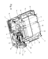
Figures 1 and 2 show in isometric view, and with parts removed for clarity, a rotary-drum home laundry dryer realized in accordance with the teachings of the present invention; -
Figure 3 is a partly-exploded isometric view of the lower supporting base or socle of theFigure 1 laundry-dryer, with parts removed for clarity; -
Figure 4 shows in isometric view, and with parts removed for clarity, the inside of theFigure 3 lower supporting base or socle of the laundry-dryer, with parts removed for clarity; -
Figure 5 is an enlarged, partly-exploded isometric view of the back of theFigure 3 lower supporting base or socle of the laundry-dryer, with parts removed for clarity; whereas -
Figure 6 is an enlarged section-view of the back of theFigure 3 lower supporting base or socle of the laundry-dryer. - With reference to
Figures 1 and 2 ,number 1 indicates as a whole a preferably household, rotary-drum laundry dryer which comprises: - a preferably, though not necessarily, parallelepiped-shaped outer
boxlike casing 2 structured for resting on the floor; - a substantially cylindrical, revolving
drum 3 structured for housing the laundry to be dried, and which is fixed in axially rotating manner inside theboxlike casing 2, directly facing a laundry loading/ unloading through opening formed in the front wall ofcasing 2; and - a
porthole door 4 hinged to the front wall ofcasing 2 to rotate about a preferably, though not necessarily, vertically-oriented reference axis, to and from a closing position in which thedoor 4 rests completely against the front wall to close the laundry loading/unloading opening and substantially airtight seal the revolvingdrum 3. - Inside the outer
boxlike casing 2, the rotary-drum laundry dryer 1 additionally comprises anelectric motor 5 which is mechanically connected to the revolvingdrum 3 for driving into rotation thedrum 3 about its longitudinal axis; a closed-circuit, hot-air generator 6 which is structured to circulate through the revolving drum 3 a stream of hot air having a low moisture level, and which flows over and rapidly dries the laundry located insidedrum 3; and finally an electroniccentral control unit 7 which controls both theelectric motor 5 and the hot-air generator 6 to perform one of the user-selectable drying cycles preferably, though not necessarily, stored in the samecentral control unit 7. - More specifically, with reference to
Figures 1 and 2 , the outerboxlike casing 2 comprises a substantially parallelepiped-shaped lower supporting base orsocle 9 which is structured for resting on the floor and for housing at least part of the hot-air generator 6; and a substantially parallelepiped-shaped upperboxlike cabinet 10 which is rigidly fixed to the top of the lower supporting base orsocle 9 and it is structured so as to house the revolvingdrum 3. - In the example shown, in particular, the revolving
drum 3 preferably extends inside theboxlike cabinet 10 coaxial to a substantially horizontally-oriented longitudinal reference axis L, and rests on a number of substantially horizontally-oriented, front and rearidle supporting rollers 11 which are located in pairs substantially at the two axial ends of the revolvingdrum 3, and are fixed in free revolving manner to thecasing 2 so as to allow the revolvingdrum 3 to freely rotate about its reference axis L inside theboxlike cabinet 10. - In the example shown, in particular, front and rear
idle supporting rollers 11 are preferably fixed in free revolving manner directly to the top of the lower supporting base orsocle 9. - The laundry loading/unloading opening of
casing 2 is therefore realized in the front wall of the upperboxlike cabinet 10, and theporthole door 4 is hinged to the front wall of the aforesaid upperboxlike cabinet 10. - In addition to the above, the lower supporting base or
socle 9 is also preferably structured so to directly support theelectric motor 5. - With reference to
Figures 1, 2 and4 , the closed-circuit, hot-air generator 6 instead preferably comprises of a heat-pump type, hot-air generator 6 which is structured for gradually drawing air from revolvingdrum 3; rapidly cooling down the air arriving from revolvingdrum 3 so to extract and retain the surplus moisture in the air drawn from revolvingdrum 3; rapidly heating the dehumidified air to a predetermined temperature, normally higher than the temperature of the air from revolvingdrum 3; and finally feeding the heated, dehumidified air back into the revolvingdrum 3, where it flows over the laundry inside the drum to rapidly dry said laundry. - In other words, with reference to
Figure 4 , hot-air generator 6 provides for continually dehumidifying and heating the air circulating inside revolvingdrum 3 to rapidly dry the laundry inside the drum, and basically comprises: - an air recirculating
conduit 12, the two ends of which are connected to the revolvingdrum 3 on opposite sides of the latter; - a
centrifugal fan 13 which is located along the air recirculatingconduit 12 to produce, inside the air recirculatingconduit 12, an airflow f which flows through the revolvingdrum 3, over the laundry located inside thedrum 3; and - a heat-
pump assembly 14 which is able to rapidly cool the airflow f coming out from revolvingdrum 3 for condensing and retaining the surplus moisture in the airflow f, and then to rapidly heat the airflow f returning back into revolvingdrum 3, so that the airflow f re-entering into revolvingdrum 3 is rapidly heated to a temperature higher than or equal to that of the airflow f coming out of the drum. - With reference to
Figures 3 to 6 , in the example shown, in particular, a central/intermediate section of theair recirculating conduit 12 extends in pass-through manner across the lower supporting base orsocle 9, and thecentrifugal fan 13 is located outside the lower supporting base orsocle 9, at the end-opening of the central section of theair recirculating conduit 12, so to directly communicate with, i.e. be fluidly connected to, the end-opening of the aforesaid central section of theair recirculating conduit 12. - In particular, the central section of the
air recirculating conduit 12 is preferably substantially horizontally-oriented inside the lower supporting base orsocle 9. Thecentrifugal fan 13 is instead preferably located on the back of the lower supporting base orsocle 9, and comprises anouter housing 15 which is located outside of the lower supporting base orsocle 9, at the end-opening of the aforesaid central section of theair recirculating conduit 12, so to directly communicate with, i.e. be fluidly connected to, said end-opening of the central section of theair recirculating conduit 12, and also with the inside of revolvingdrum 3; and animpeller 16 which is housed in axially rotating manner inside theouter housing 15 to generate the airflow f when rotating about its reference axis A. - With reference to
Figure 4 , the heat-pump assembly 14 in turn comprises: - a first air/
refrigerant heat exchanger 17 which is located along theair recirculating conduit 12, i.e. inside the lower supporting base orsocle 9, and is structured for rapidly cooling down the airflow f arriving from revolvingdrum 3 to condense and restrain the surplus moisture in the airflow f; - a second air/
refrigerant heat exchanger 18 which is located along theair recirculating conduit 12, i.e. inside the lower supporting base orsocle 9, downstream ofheat exchanger 17, and which is structured for rapidly heating the airflow f arriving fromheat exchanger 17 and directed back to revolvingdrum 3, so that the airflow f re-entering into revolvingdrum 3 is heated rapidly to a temperature higher than or equal to that of the air flowing out of revolvingdrum 3; - an electrically-powered
refrigerant compressing device 19 which is interposed between the refrigerant-outlet ofheat exchanger 17 and the refrigerant-inlet ofheat exchanger 18, and which is structured for compressing the gaseous-state refrigerant directed towardsheat exchanger 18 so that refrigerant pressure and temperature are much higher at the refrigerant-inlet ofheat exchanger 18 than at the refrigerant-outlet ofheat exchanger 17; and finally - an expansion valve or similar passive/operated refrigerant expansion device (for example a capillary tube, a thermostatic valve or an electrically-controlled expansion valve) which is interposed between the refrigerant-outlet of
heat exchanger 18 and the refrigerant-inlet ofheat exchanger 17, and it is structured so as to cause a rapid expansion of the refrigerant directed towards the first air/refrigerant heat exchanger 17, so that refrigerant pressure and temperature are much higher at the refrigerant-outlet ofheat exchanger 18 than at the refrigerant-inlet ofheat exchanger 17. - The air/
refrigerant heat exchanger 17 is conventionally referred to as the "evaporator" or "gas-heater" of the heat-pump assembly 14, and it is structured so that the airflow f arriving from revolvingdrum 3 and the low-pressure and low-temperature refrigerant directed to the suction of therefrigerant compressing device 19 can flow through it simultaneously, allowing the refrigerant having a temperature lower than that of the airflow f, to absorb heat from the airflow f, thus causing condensation of the surplus moisture in the airflow f arriving from revolvingdrum 3. - The air/
refrigerant heat exchanger 18, in turn, is conventionally referred to as the "condenser" or "gas-cooler" of the heat-pump assembly 14, and it is structured so that the airflow f directed back into revolvingdrum 3 and the high-pressure and high-temperature refrigerant arriving from the delivery of therefrigerant compressing device 19 can flow through it simultaneously, allowing the refrigerant having a temperature greater than that of the airflow f to release heat to the airflow f, thus rapidly heating the airflow f directed back into the revolvingdrum 3. - With reference to
Figures 3-6 , inlaundry dryer 1 thecentrifugal fan 13 additionally comprises a substantially funnel-shaped,intake manifold 20 which is fixed in a rigid and stable, though easily removable, manner to the lower supporting base orsocle 9, at the end-opening of the central section of theair recirculating conduit 12, and extends within theouter housing 15 towards theimpeller 16 while remaining locally substantially coaxial to the impeller rotation axis A. - In other words, the
intake manifold 20 extends within theouter housing 15 locally substantially coaxial to the impeller supporting shaft, and theimpeller 16 is rigidly fitted at the axial end of the supporting shaft that extends through theintake manifold 20 and juts out of theintake manifold 20. - With reference to
Figures 4 ,5 and6 , in the example shown, in particular, theelectric motor 5 is preferably fixed/recessed on the lower supporting base orsocle 9 so that itsdrive shaft 5a sticks out from the back of the lower supporting base orsocle 9, at the end-opening of the central section of theair recirculating conduit 12; and thecentrifugal fan 13 is located on the back of the lower supporting base orsocle 9, locally substantially aligned to thedrive shaft 5a ofelectric motor 5, so that theintake manifold 20 extends within theouter housing 15 locally substantially coaxial to thedrive shaft 5a ofelectric motor 5, and theimpeller 19 is rigidly fitted to the axial end of thedrive shaft 5a ofelectric motor 5 so to be directly driven into rotation by the latter. - With reference to
Figures 3-6 , theouter housing 15 in turn comprises afirst portion 15a directly adjoining the lower supporting base orsocle 9, at the end-opening of the central section of theair recirculating conduit 12, and asecond portion 15b which is structured/shaped for being coupled in a rigid and stable, though easily releasable, manner to thefirst portion 15a of theouter housing 16 so to close thefirst portion 15a ofouter housing 15 for covering up theimpeller 16 at least partly recessed inside thefirst portion 15a ofouter housing 15. - With reference to
Figures 3 to 6 , in particular, thefirst portion 15a ofouter housing 15 is preferably realized in one piece with the lower supporting base orsocle 9, whereas thesecond portion 15b ofouter housing 15 consists in a substantially basin-shaped,rigid cover 15b which is fixed in a rigid and stable, though easily releasable, manner to the area of the lower supporting base orsocle 9 forming thefirst portion 15a ofouter housing 15, so as to substantially airtight close saidfirst portion 15a and completely cover theimpeller 19. - In particular, with reference to
Figures 3 and4 , in the example shown the lower supporting base orsocle 9 of theouter casing 2 is formed/composed by a lower half-shell 9a which is structured for resting on the floor, and by an upper half-shell 9b which is structured for being stacked up on top of, and rigidly coupled to, the lower half-shell 9a, so to preferably directly support the parallelepiped-shaped upperboxlike cabinet 10 and preferably also the front and rearidle rollers 11 that support in free revolving manner the revolvingdrum 3. - These lower half-
shell 9a and upper half-shell 9b are structured/shaped so as to form, when coupled to one another, the substantially horizontally-oriented, whole central section of theair recirculating conduit 12 that is shaped/dimensioned so as to house, one after the other along the flowing direction of the airflow f, both theevaporator 17 and thecondenser 18 of the heat-pump assembly 14. - In other words, the lower half-
shell 9a and upper half-shell 9b are shaped so as to form the two halves of the aforesaid central section of theair recirculating conduit 12, and are structured for being substantially airtight coupled to one another, so as to compose/form the whole central section of theair recirculating conduit 12. - In the example shown, the lower half-
shell 9a and the upper half-shell 9b are both preferably, though not necessarily, realized in plastic material by means of an injection molding process. - With reference to
Figures 3 and6 , the end-opening of the central section of theair recirculating conduit 12 is therefore preferably delimited/formed by both the lower half-shell 9a and the upper half-shell 9b, and theintake manifold 20 is preferably, though not necessarily, directly jammed in between the aforesaid lower half-shell 9a and upper half-shell 9b, at the end-opening of the central section of theair recirculating conduit 12. - In the example shown in particular, the
intake manifold 20 consists in a substantiallyfrustoconical sleeve 20 which preferably made of plastic material, and is provided with an outwards projectingperipheral flange 20a extending all-around the larger mouth. - This
peripheral flange 20a is structured to fit into two corresponding coplanar semicircular grooves realized one in the lower half-shell 9a and the other in the upper half-shell 9b, so to trap and firmly fix thesleeve 20 between the lower half-shell 9a and the upper half-shell 9b when said half-shells air recirculating conduit 12. - In addition to the above, with reference to
Figures 3 to 6 , thecentrifugal fan 13 of hot-air generator 6 is preferably also partly recessed and integrated on the back of the lower supporting base orsocle 9 formed by the two half-shells - In particular, the
first portion 15a of theouter housing 15 ofcentrifugal fan 13 is preferably divided into two distinct and separated sections which are realized in one piece, respectively, with the lower half-shell 9a and with the upper half-shell 9b, so that the wholefirst portion 15a of theouter housing 15 is formed when the two half-shells - In the example shown, in particular, the aforesaid two distinct and separated sections forming the
first portion 15a ofouter housing 15 are preferably structured and shaped so as to form, when firmly coupled to one another, a first approximately half-volute of theouter housing 15; whereas thesecond portion 15b ofouter housing 15 preferably consists in a substantially basin-shaped,rigid cover 15b which is shaped so as to form the remaining, complementary second half-volute of theouter housing 15, and is structured for being substantially airtight coupled to the first half-volute 15a formed by the two half-shells outer housing 15 ofcentrifugal fan 13. - In other words, the
outer housing 15 ofcentrifugal fan 13 is spitted into three distinct and separated pieces which are structured for being substantially airtight coupled to one another to form the volute of theouter housing 15. - In addition to the above, with reference to
Figures 3-6 , in the example shown the lower half-shell 9a and upper half-shell 9b are also preferably, though not necessarily, structured so that the central section of theair recirculating conduit 12 is substantially L-shaped, and is oriented so that a first portion of the central section of theair recirculating conduit 12 extends below the revolvingdrum 3 while remaining locally substantially parallel to the longitudinal axis L of revolvingdrum 3, and that a second transversal portion of the central section of theair recirculating conduit 12 extends below the revolvingdrum 3 remaining locally substantially perpendicular to the longitudinal axis L ofdrum 3. - The
evaporator 17 and thecondenser 18 of the heat-pump assembly 14 are preferably located, one downstream the other, inside the first portion of the aforesaid central section of theair recirculating conduit 12; whereas therefrigerant compressing device 19 and theelectric motor 5 are preferably fixed/recessed on the lower supporting base orsocle 9, aligned one after the other in a direction locally substantially parallel to the longitudinal axis L of revolvingdrum 3, beside the first portion of the central section of theair recirculating conduit 12, so that thedrive shaft 5a ofelectric motor 5 sticks out from the back of the lower supporting base orsocle 9, at the end of the second portion of the central section of theair recirculating conduit 12. - In the example shown, in particular,
electric motor 5 andrefrigerant compressing device 19 are preferably fixed/recessed directly onto the lower half-shell 9a, beside the first portion of the central section of theair recirculating conduit 12. - With reference to
Figures 4 and6 , thecentrifugal fan 13 is therefore located on the back of the lower supporting base orsocle 9, at the end of the second portion of the central section of theair recirculating conduit 12, locally aligned to thedrive shaft 5a of theelectric motor 5. - In other words, the
first portion 15a ofouter housing 15 is realized on the back of the lower supporting base orsocle 9, locally aligned to thedrive shaft 5a of theelectric motor 5, so that the center of the first half-volute 15a directly communicates with, i.e. is fluidly connected to, the end-opening of the second portion of the central section of theair recirculating conduit 12, and the substantiallyfrustoconical sleeve 20 forming theintake manifold 20 protrudes from the center of the aforesaid first half-volute 15a towards theimpeller 16 while remaining locally substantially coaxial to thedrive shaft 5a ofelectric motor 5. - General operation of the rotary-drum home laundry drier 1 is clearly inferable from the above description, with no further explanation required.
- The advantages connected to the particular structure of lower supporting base or
socle 9 and of thecentrifugal fan 13 are large in number. - First of all, thanks to the presence of the easily
removable intake manifold 20, thecentrifugal fan 13 can useimpellers 16 of different diameter with no structural modifications to theouter housing 15, thus allowing, during assembly of thelaundry dryer 1, a cheap and rapid adaptation of the impeller dimensions to the actual performance of theelectric motor 5 fixed on the lower supporting base orsocle 9 to minimize electricity consumption. - In fact, on the basis the engine power of the
electric motor 5 fixed on the lower supporting base orsocle 9, the operator can choose the mostappropriate impeller 16 and quickly fit it onto thedrive shaft 5a together with the corresponding funnel-shapedintake manifold 20. - Moreover, the quick replacement of the
intake manifold 20 allows to useintake manifolds 20 of different axial length to compensate limited axial displacements of the drivingshaft 5a. - Clearly, changes may be made to the rotary-drum laundry drier 1 as described herein without, however, departing from the scope of the present invention.
- For example, in a less sophisticated embodiment the closed-circuit, hot-
air generator 6 may consist of a forced-air, hot-air generator in which the cooling of the airflow f arriving from the revolvingdrum 3 is performed via a cold airflow arriving from the outside ofcasing 2. - More specifically, in this less sophisticated embodiment, the hot-
air generator 6 lacks theevaporator 17, thecondenser 18, therefrigerant compressing device 19 and the refrigerant expansion device, and instead comprises: an air/air heat exchanger which is located along the central section of theair recirculating conduit 12, in place of theevaporator 17; and a resistor or similar air-heating device which is located along theair recirculating conduit 12, downstream of said air/air heat exchanger. - The air/air heat exchanger is structured for being crossed, at the same time, by the airflow f arriving from revolving
drum 3 and by a stream of cold air arriving from outside thecasing 2, thus allowing the stream of external cold air to absorb heat from the airflow f for causing the condensation of the surplus moisture in the airflow f arriving from revolvingdrum 3; whereas the resistor is structured for rapidly heating up the dehumidified air directed back into the revolvingdrum 3.
Claims (14)
- Rotary-drum laundry dryer (1) comprising a revolving drum (3) structured for housing the laundry to be dried, a hot-air generator (6) structured to circulate a stream of hot air through said revolving drum (3), and a lower supporting base or socle (9) which is structured for resting on the floor and for housing at least part of the hot-air generator (6);
the hot-air generator (6) in turn comprising: an air recirculating conduit (12) having its two ends connected to the revolving drum (3); air circulating means (13) which are located along the air recirculating conduit (12) and are structured to produce, inside the air recirculating conduit (12), an airflow (f) which flows through the revolving drum (3) and over the laundry inside the drum (3); and at least one heat exchanger (17) located along the air recirculating conduit (12) and structured to cool the moist air arriving from the rotatable drum (3) so to cause the condensation of the surplus moisture inside the airflow (f);
a section of the air recirculating conduit (12) extending across the lower supporting base or socle (9), and being structured so as to house said at least one heat exchanger (17) of the hot-air generator (6);
the air circulating means (13) comprising an impeller housing (15) which is located and communicates with an end-opening of said section of the air recirculating conduit (12), and an impeller (16) which is housed in axially rotating manner inside the impeller housing (15) to generate said airflow (f);
the laundry dryer (1) being characterized in that the air circulating means (13) additionally comprise a substantially funnel-shaped, intake manifold (20) which is fixed in a rigid and stable, though easily removable, manner to said lower supporting base or socle (9), at the end-opening of said central of the air recirculating conduit (12), and extends within the impeller housing (15) towards the impeller (16). - Rotary-drum laundry dryer according to Claim 1, characterized in that the lower supporting base or socle (9) comprises a lower half-shell (9a) structured for resting on the floor, and an upper half-shell (9b) stacked up on top of, and rigidly coupled to said lower half-shell (9a); said lower half-shell (9a) and upper half-shell (9b) being shaped so as to form, when coupled to one another, said section of the air recirculating conduit (12) which houses said at least one heat exchanger (17) of the hot-air generator (6).
- Rotary-drum laundry dryer according to Claim 2, characterized in that the end-opening of said central of the air recirculating conduit (12) is delimited/formed by the lower half-shell (9a) and by the upper half-shell (9b); and in that said intake manifold (20) is jammed in between said lower and upper half-shells (9a, 9b), at the end-opening of said central of the air recirculating conduit (12).
- Rotary-drum laundry dryer according to any one of the foregoing claims, characterized in that the impeller housing (15) comprises a first portion (15a) directly associated to said lower supporting base or socle (9), and a second portion (15b) structured/shaped for being coupled in a rigid and stable, though easily releasable, manner to the first portion (15a) of the impeller housing (15) to close said first portion and cover the impeller (16).
- Rotary-drum laundry dryer according to Claim 5, characterized in that the first portion (15a) of the impeller housing (15) is realized in one piece with said lower supporting base or socle (9), and in that second portion (15b) of the impeller housing (15) comprises a substantially basin-shaped cover (15) which is fixed in a rigid and stable, though easily releasable, manner to the part of said lower supporting base or socle (9) forming the first portion (15a) of the impeller housing (15), so as to close the first portion (15a) of the impeller housing (15) and completely cover said impeller (9).
- Rotary-drum laundry dryer according to Claim any one of claims 2-5, characterized in that the first portion (15a) of the impeller housing (15) is partly realized in one piece with the lower half-shell (9a) and partly in one piece with the upper half-shell (9b).
- Rotary-drum laundry dryer according to any one of the foregoing claims, characterized in that said intake manifold (20) consists in a substantially frustoconical sleeve (20).
- Rotary-drum laundry dryer according to Claims 7, characterized in that said frustoconical sleeve (20) is provided, all-around the larger mouth, with an outwards projecting peripheral flange (20a) which is structured to fit into two corresponding coplanar grooves realized one in the lower half-shell (9a), and the other in the upper half-shell (9b).
- Rotary-drum laundry dryer according to any one of the foregoing claims, characterized in that impeller (16) of the air circulating means (13) is rigidly fitted to the axial end of a drive shaft (5a) extending through said intake manifold (20).
- Rotary-drum laundry dryer according to Claim 9, characterized by also comprising an electric motor assembly (5) which is mechanically connected to the revolving drum (3) for rotating said drum (3) about its longitudinal axis (L); said electric motor assembly (5) being fixed on said lower supporting base or socle (9) so that an axial end of the drive shaft (5a) of said electric motor assembly (5) sticks out of the lower supporting base or socle (9), through said intake manifold (20), to support and drive into rotation said impeller (16).
- Rotary-drum laundry dryer according to any one of the foregoing claims, characterized by also comprising an upper boxlike cabinet (10) which is rigidly fixed to the top of the lower supporting base or socle (9) and is structured so to house the revolving drum (3).
- Rotary-drum laundry dryer according to Claim 11, characterized in that the longitudinal axis (L) of the revolving drum (3) is substantially horizontally-oriented, and in that the revolving drum (3) rests on a number of supporting rollers (11) which are arranged substantially at the two axial ends of the revolving drum (3), and are fixed in free revolving manner directly to the top of said lower supporting base or socle (9).
- Rotary-drum laundry dryer according to Claim 12, characterized in that the supporting rollers (11) are fixed in free revolving manner directly to the upper half-shell (9b) of the lower supporting base or socle (9).
- Rotary-drum laundry dryer according to any one of the foregoing claims, characterized in that the hot-air generator (6) is a heat-pump type, hot-air generator (6) which comprises:- a first air/refrigerant heat exchanger (17) which is located inside said section of the air recirculating conduit (12), and is structured for rapidly cooling down the airflow (f) arriving from the revolving drum (3) to condense and restrain the surplus moisture in the airflow (f);- a second air/refrigerant heat exchanger (18) which is located inside said section of the air recirculating conduit (12), downstream of the first air/refrigerant heat exchanger (17), and which is structured for rapidly heating the airflow (f) arriving from the first air/refrigerant heat exchanger (17) and directed back to the revolving drum (3);- a refrigerant compressing device (19) which is interposed between the refrigerant-outlet of the first air/refrigerant heat exchanger (17) and the refrigerant-inlet of the second air/refrigerant heat exchanger (18), and which is structured for compressing the gaseous-state refrigerant directed towards the second air/refrigerant heat exchanger (18); and- a refrigerant expansion device which is interposed between the refrigerant-outlet of the second air/refrigerant heat exchanger (18) and the refrigerant-inlet of the first air/refrigerant heat exchanger (17), and it is structured so as to cause a rapid expansion of the refrigerant directed towards the first air/refrigerant heat exchanger (17).
Priority Applications (1)
| Application Number | Priority Date | Filing Date | Title |
|---|---|---|---|
| EP11167968.4A EP2527524B1 (en) | 2011-05-27 | 2011-05-27 | Rotary-drum laundry dryer |
Applications Claiming Priority (1)
| Application Number | Priority Date | Filing Date | Title |
|---|---|---|---|
| EP11167968.4A EP2527524B1 (en) | 2011-05-27 | 2011-05-27 | Rotary-drum laundry dryer |
Publications (2)
| Publication Number | Publication Date |
|---|---|
| EP2527524A1 true EP2527524A1 (en) | 2012-11-28 |
| EP2527524B1 EP2527524B1 (en) | 2015-08-05 |
Family
ID=44721124
Family Applications (1)
| Application Number | Title | Priority Date | Filing Date |
|---|---|---|---|
| EP11167968.4A Not-in-force EP2527524B1 (en) | 2011-05-27 | 2011-05-27 | Rotary-drum laundry dryer |
Country Status (1)
| Country | Link |
|---|---|
| EP (1) | EP2527524B1 (en) |
Cited By (1)
| Publication number | Priority date | Publication date | Assignee | Title |
|---|---|---|---|---|
| US20210207314A1 (en) * | 2018-06-04 | 2021-07-08 | Electrolux Professional Ab | Tumble dryer |
Families Citing this family (2)
| Publication number | Priority date | Publication date | Assignee | Title |
|---|---|---|---|---|
| EP3899127B1 (en) | 2018-12-21 | 2024-03-13 | Electrolux Appliances Aktiebolag | Laundry dryer |
| PL3899128T3 (en) | 2018-12-21 | 2024-07-22 | Electrolux Appliances Aktiebolag | LAUNDRY DRYER |
Citations (5)
| Publication number | Priority date | Publication date | Assignee | Title |
|---|---|---|---|---|
| US20050217139A1 (en) * | 2004-04-06 | 2005-10-06 | Lg Electronics Inc. | Clothes dryer |
| DE102006023952A1 (en) * | 2005-05-23 | 2006-11-30 | Lg Electronics Inc. | clothes dryer |
| DE202006018205U1 (en) * | 2006-11-06 | 2007-02-15 | V-Zug Ag | Clothes dryer with a drum and a heat pump circuit comprising a condenser, a throttle, an evaporator and a compressor comprises an auxiliary heat exchanger between the condenser and the throttle |
| EP1990465A1 (en) * | 2007-05-07 | 2008-11-12 | MIELE & CIE. KG | Tumble dryer with an air canal |
| EP2166145A1 (en) * | 2008-09-23 | 2010-03-24 | Samsung Electronics Co., Ltd. | Clothing dryer |
-
2011
- 2011-05-27 EP EP11167968.4A patent/EP2527524B1/en not_active Not-in-force
Patent Citations (6)
| Publication number | Priority date | Publication date | Assignee | Title |
|---|---|---|---|---|
| US20050217139A1 (en) * | 2004-04-06 | 2005-10-06 | Lg Electronics Inc. | Clothes dryer |
| DE102006023952A1 (en) * | 2005-05-23 | 2006-11-30 | Lg Electronics Inc. | clothes dryer |
| DE202006018205U1 (en) * | 2006-11-06 | 2007-02-15 | V-Zug Ag | Clothes dryer with a drum and a heat pump circuit comprising a condenser, a throttle, an evaporator and a compressor comprises an auxiliary heat exchanger between the condenser and the throttle |
| EP2034084A1 (en) | 2006-11-06 | 2009-03-11 | V-Zug AG | Clothes drier with auxiliary heat exchanger |
| EP1990465A1 (en) * | 2007-05-07 | 2008-11-12 | MIELE & CIE. KG | Tumble dryer with an air canal |
| EP2166145A1 (en) * | 2008-09-23 | 2010-03-24 | Samsung Electronics Co., Ltd. | Clothing dryer |
Cited By (2)
| Publication number | Priority date | Publication date | Assignee | Title |
|---|---|---|---|---|
| US20210207314A1 (en) * | 2018-06-04 | 2021-07-08 | Electrolux Professional Ab | Tumble dryer |
| US12221742B2 (en) * | 2018-06-04 | 2025-02-11 | Electrolux Professional Ab | Tumble dryer |
Also Published As
| Publication number | Publication date |
|---|---|
| EP2527524B1 (en) | 2015-08-05 |
Similar Documents
| Publication | Publication Date | Title |
|---|---|---|
| AU2012265068B2 (en) | Rotary-drum laundry dryer | |
| AU2012265068A1 (en) | Rotary-drum laundry dryer | |
| CN1973077B (en) | clothes dryer | |
| EP2527526B1 (en) | Rotary-drum laundry dryer | |
| EP2990524B1 (en) | Heat pump laundry dryer | |
| EP2527523B1 (en) | Rotary-drum laundry dryer | |
| EP2743394A1 (en) | Heat pump laundry treatment apparatus | |
| EP2592184A1 (en) | Rotary-drum laundry dryer | |
| EP2708638A1 (en) | Rotary-drum laundry dryer | |
| EP2843114B1 (en) | Rotary-drum laundry dryer | |
| EP2527525B1 (en) | Rotary-drum laundry dryer | |
| EP2860304B1 (en) | Rotary-drum laundry dryer | |
| EP2527527B1 (en) | Rotary-drum laundry dryer | |
| EP2931962B1 (en) | Heat pump laundry treatment apparatus | |
| EP2527524B1 (en) | Rotary-drum laundry dryer | |
| RU2452804C2 (en) | Household drying device for clothes | |
| EP2843112B1 (en) | Rotary-drum laundry dryer | |
| EP2147999A1 (en) | Home laundry drier | |
| EP2631356B1 (en) | Rotary-drum laundry dryer | |
| EP2631357B1 (en) | Rotary-drum laundry dryer | |
| KR101750866B1 (en) | Clothes dryer | |
| EP2631352A1 (en) | Rotary-drum laundry dryer |
Legal Events
| Date | Code | Title | Description |
|---|---|---|---|
| PUAI | Public reference made under article 153(3) epc to a published international application that has entered the european phase |
Free format text: ORIGINAL CODE: 0009012 |
|
| AK | Designated contracting states |
Kind code of ref document: A1 Designated state(s): AL AT BE BG CH CY CZ DE DK EE ES FI FR GB GR HR HU IE IS IT LI LT LU LV MC MK MT NL NO PL PT RO RS SE SI SK SM TR |
|
| AX | Request for extension of the european patent |
Extension state: BA ME |
|
| 17P | Request for examination filed |
Effective date: 20130528 |
|
| RBV | Designated contracting states (corrected) |
Designated state(s): AL AT BE BG CH CY CZ DE DK EE ES FI FR GB GR HR HU IE IS IT LI LT LU LV MC MK MT NL NO PL PT RO RS SE SI SK SM TR |
|
| 17Q | First examination report despatched |
Effective date: 20130820 |
|
| GRAP | Despatch of communication of intention to grant a patent |
Free format text: ORIGINAL CODE: EPIDOSNIGR1 |
|
| INTG | Intention to grant announced |
Effective date: 20150323 |
|
| GRAS | Grant fee paid |
Free format text: ORIGINAL CODE: EPIDOSNIGR3 |
|
| GRAA | (expected) grant |
Free format text: ORIGINAL CODE: 0009210 |
|
| AK | Designated contracting states |
Kind code of ref document: B1 Designated state(s): AL AT BE BG CH CY CZ DE DK EE ES FI FR GB GR HR HU IE IS IT LI LT LU LV MC MK MT NL NO PL PT RO RS SE SI SK SM TR |
|
| REG | Reference to a national code |
Ref country code: GB Ref legal event code: FG4D |
|
| REG | Reference to a national code |
Ref country code: CH Ref legal event code: EP |
|
| REG | Reference to a national code |
Ref country code: AT Ref legal event code: REF Ref document number: 740787 Country of ref document: AT Kind code of ref document: T Effective date: 20150815 |
|
| REG | Reference to a national code |
Ref country code: IE Ref legal event code: FG4D |
|
| REG | Reference to a national code |
Ref country code: DE Ref legal event code: R096 Ref document number: 602011018397 Country of ref document: DE |
|
| REG | Reference to a national code |
Ref country code: AT Ref legal event code: MK05 Ref document number: 740787 Country of ref document: AT Kind code of ref document: T Effective date: 20150805 |
|
| REG | Reference to a national code |
Ref country code: LT Ref legal event code: MG4D |
|
| REG | Reference to a national code |
Ref country code: NL Ref legal event code: MP Effective date: 20150805 |
|
| PG25 | Lapsed in a contracting state [announced via postgrant information from national office to epo] |
Ref country code: LT Free format text: LAPSE BECAUSE OF FAILURE TO SUBMIT A TRANSLATION OF THE DESCRIPTION OR TO PAY THE FEE WITHIN THE PRESCRIBED TIME-LIMIT Effective date: 20150805 Ref country code: NO Free format text: LAPSE BECAUSE OF FAILURE TO SUBMIT A TRANSLATION OF THE DESCRIPTION OR TO PAY THE FEE WITHIN THE PRESCRIBED TIME-LIMIT Effective date: 20151105 Ref country code: FI Free format text: LAPSE BECAUSE OF FAILURE TO SUBMIT A TRANSLATION OF THE DESCRIPTION OR TO PAY THE FEE WITHIN THE PRESCRIBED TIME-LIMIT Effective date: 20150805 Ref country code: LV Free format text: LAPSE BECAUSE OF FAILURE TO SUBMIT A TRANSLATION OF THE DESCRIPTION OR TO PAY THE FEE WITHIN THE PRESCRIBED TIME-LIMIT Effective date: 20150805 Ref country code: GR Free format text: LAPSE BECAUSE OF FAILURE TO SUBMIT A TRANSLATION OF THE DESCRIPTION OR TO PAY THE FEE WITHIN THE PRESCRIBED TIME-LIMIT Effective date: 20151106 |
|
| PG25 | Lapsed in a contracting state [announced via postgrant information from national office to epo] |
Ref country code: SE Free format text: LAPSE BECAUSE OF FAILURE TO SUBMIT A TRANSLATION OF THE DESCRIPTION OR TO PAY THE FEE WITHIN THE PRESCRIBED TIME-LIMIT Effective date: 20150805 Ref country code: IS Free format text: LAPSE BECAUSE OF FAILURE TO SUBMIT A TRANSLATION OF THE DESCRIPTION OR TO PAY THE FEE WITHIN THE PRESCRIBED TIME-LIMIT Effective date: 20151205 Ref country code: PT Free format text: LAPSE BECAUSE OF FAILURE TO SUBMIT A TRANSLATION OF THE DESCRIPTION OR TO PAY THE FEE WITHIN THE PRESCRIBED TIME-LIMIT Effective date: 20151207 Ref country code: HR Free format text: LAPSE BECAUSE OF FAILURE TO SUBMIT A TRANSLATION OF THE DESCRIPTION OR TO PAY THE FEE WITHIN THE PRESCRIBED TIME-LIMIT Effective date: 20150805 Ref country code: RS Free format text: LAPSE BECAUSE OF FAILURE TO SUBMIT A TRANSLATION OF THE DESCRIPTION OR TO PAY THE FEE WITHIN THE PRESCRIBED TIME-LIMIT Effective date: 20150805 Ref country code: PL Free format text: LAPSE BECAUSE OF FAILURE TO SUBMIT A TRANSLATION OF THE DESCRIPTION OR TO PAY THE FEE WITHIN THE PRESCRIBED TIME-LIMIT Effective date: 20150805 Ref country code: ES Free format text: LAPSE BECAUSE OF FAILURE TO SUBMIT A TRANSLATION OF THE DESCRIPTION OR TO PAY THE FEE WITHIN THE PRESCRIBED TIME-LIMIT Effective date: 20150805 Ref country code: AT Free format text: LAPSE BECAUSE OF FAILURE TO SUBMIT A TRANSLATION OF THE DESCRIPTION OR TO PAY THE FEE WITHIN THE PRESCRIBED TIME-LIMIT Effective date: 20150805 |
|
| PG25 | Lapsed in a contracting state [announced via postgrant information from national office to epo] |
Ref country code: NL Free format text: LAPSE BECAUSE OF FAILURE TO SUBMIT A TRANSLATION OF THE DESCRIPTION OR TO PAY THE FEE WITHIN THE PRESCRIBED TIME-LIMIT Effective date: 20150805 |
|
| PG25 | Lapsed in a contracting state [announced via postgrant information from national office to epo] |
Ref country code: CZ Free format text: LAPSE BECAUSE OF FAILURE TO SUBMIT A TRANSLATION OF THE DESCRIPTION OR TO PAY THE FEE WITHIN THE PRESCRIBED TIME-LIMIT Effective date: 20150805 Ref country code: DK Free format text: LAPSE BECAUSE OF FAILURE TO SUBMIT A TRANSLATION OF THE DESCRIPTION OR TO PAY THE FEE WITHIN THE PRESCRIBED TIME-LIMIT Effective date: 20150805 Ref country code: EE Free format text: LAPSE BECAUSE OF FAILURE TO SUBMIT A TRANSLATION OF THE DESCRIPTION OR TO PAY THE FEE WITHIN THE PRESCRIBED TIME-LIMIT Effective date: 20150805 Ref country code: SK Free format text: LAPSE BECAUSE OF FAILURE TO SUBMIT A TRANSLATION OF THE DESCRIPTION OR TO PAY THE FEE WITHIN THE PRESCRIBED TIME-LIMIT Effective date: 20150805 |
|
| REG | Reference to a national code |
Ref country code: DE Ref legal event code: R097 Ref document number: 602011018397 Country of ref document: DE |
|
| REG | Reference to a national code |
Ref country code: FR Ref legal event code: PLFP Year of fee payment: 6 |
|
| PG25 | Lapsed in a contracting state [announced via postgrant information from national office to epo] |
Ref country code: RO Free format text: LAPSE BECAUSE OF FAILURE TO SUBMIT A TRANSLATION OF THE DESCRIPTION OR TO PAY THE FEE WITHIN THE PRESCRIBED TIME-LIMIT Effective date: 20150805 |
|
| PLBE | No opposition filed within time limit |
Free format text: ORIGINAL CODE: 0009261 |
|
| STAA | Information on the status of an ep patent application or granted ep patent |
Free format text: STATUS: NO OPPOSITION FILED WITHIN TIME LIMIT |
|
| 26N | No opposition filed |
Effective date: 20160509 |
|
| PGFP | Annual fee paid to national office [announced via postgrant information from national office to epo] |
Ref country code: GB Payment date: 20160520 Year of fee payment: 6 |
|
| PG25 | Lapsed in a contracting state [announced via postgrant information from national office to epo] |
Ref country code: SI Free format text: LAPSE BECAUSE OF FAILURE TO SUBMIT A TRANSLATION OF THE DESCRIPTION OR TO PAY THE FEE WITHIN THE PRESCRIBED TIME-LIMIT Effective date: 20150805 Ref country code: BE Free format text: LAPSE BECAUSE OF NON-PAYMENT OF DUE FEES Effective date: 20160531 |
|
| PGFP | Annual fee paid to national office [announced via postgrant information from national office to epo] |
Ref country code: FR Payment date: 20160520 Year of fee payment: 6 |
|
| PG25 | Lapsed in a contracting state [announced via postgrant information from national office to epo] |
Ref country code: BE Free format text: LAPSE BECAUSE OF FAILURE TO SUBMIT A TRANSLATION OF THE DESCRIPTION OR TO PAY THE FEE WITHIN THE PRESCRIBED TIME-LIMIT Effective date: 20150805 Ref country code: LU Free format text: LAPSE BECAUSE OF FAILURE TO SUBMIT A TRANSLATION OF THE DESCRIPTION OR TO PAY THE FEE WITHIN THE PRESCRIBED TIME-LIMIT Effective date: 20160527 |
|
| REG | Reference to a national code |
Ref country code: CH Ref legal event code: PL |
|
| PG25 | Lapsed in a contracting state [announced via postgrant information from national office to epo] |
Ref country code: CH Free format text: LAPSE BECAUSE OF NON-PAYMENT OF DUE FEES Effective date: 20160531 Ref country code: LI Free format text: LAPSE BECAUSE OF NON-PAYMENT OF DUE FEES Effective date: 20160531 |
|
| REG | Reference to a national code |
Ref country code: IE Ref legal event code: MM4A |
|
| PG25 | Lapsed in a contracting state [announced via postgrant information from national office to epo] |
Ref country code: IE Free format text: LAPSE BECAUSE OF NON-PAYMENT OF DUE FEES Effective date: 20160527 |
|
| GBPC | Gb: european patent ceased through non-payment of renewal fee |
Effective date: 20170527 |
|
| REG | Reference to a national code |
Ref country code: FR Ref legal event code: ST Effective date: 20180131 |
|
| PG25 | Lapsed in a contracting state [announced via postgrant information from national office to epo] |
Ref country code: GB Free format text: LAPSE BECAUSE OF NON-PAYMENT OF DUE FEES Effective date: 20170527 |
|
| PG25 | Lapsed in a contracting state [announced via postgrant information from national office to epo] |
Ref country code: CY Free format text: LAPSE BECAUSE OF FAILURE TO SUBMIT A TRANSLATION OF THE DESCRIPTION OR TO PAY THE FEE WITHIN THE PRESCRIBED TIME-LIMIT Effective date: 20150805 Ref country code: HU Free format text: LAPSE BECAUSE OF FAILURE TO SUBMIT A TRANSLATION OF THE DESCRIPTION OR TO PAY THE FEE WITHIN THE PRESCRIBED TIME-LIMIT; INVALID AB INITIO Effective date: 20110527 Ref country code: FR Free format text: LAPSE BECAUSE OF NON-PAYMENT OF DUE FEES Effective date: 20170531 Ref country code: SM Free format text: LAPSE BECAUSE OF FAILURE TO SUBMIT A TRANSLATION OF THE DESCRIPTION OR TO PAY THE FEE WITHIN THE PRESCRIBED TIME-LIMIT Effective date: 20150805 |
|
| PG25 | Lapsed in a contracting state [announced via postgrant information from national office to epo] |
Ref country code: MC Free format text: LAPSE BECAUSE OF FAILURE TO SUBMIT A TRANSLATION OF THE DESCRIPTION OR TO PAY THE FEE WITHIN THE PRESCRIBED TIME-LIMIT Effective date: 20150805 Ref country code: MK Free format text: LAPSE BECAUSE OF FAILURE TO SUBMIT A TRANSLATION OF THE DESCRIPTION OR TO PAY THE FEE WITHIN THE PRESCRIBED TIME-LIMIT Effective date: 20150805 Ref country code: TR Free format text: LAPSE BECAUSE OF FAILURE TO SUBMIT A TRANSLATION OF THE DESCRIPTION OR TO PAY THE FEE WITHIN THE PRESCRIBED TIME-LIMIT Effective date: 20150805 Ref country code: MT Free format text: LAPSE BECAUSE OF NON-PAYMENT OF DUE FEES Effective date: 20160531 |
|
| PG25 | Lapsed in a contracting state [announced via postgrant information from national office to epo] |
Ref country code: BG Free format text: LAPSE BECAUSE OF FAILURE TO SUBMIT A TRANSLATION OF THE DESCRIPTION OR TO PAY THE FEE WITHIN THE PRESCRIBED TIME-LIMIT Effective date: 20150805 |
|
| PG25 | Lapsed in a contracting state [announced via postgrant information from national office to epo] |
Ref country code: AL Free format text: LAPSE BECAUSE OF FAILURE TO SUBMIT A TRANSLATION OF THE DESCRIPTION OR TO PAY THE FEE WITHIN THE PRESCRIBED TIME-LIMIT Effective date: 20150805 |
|
| PGFP | Annual fee paid to national office [announced via postgrant information from national office to epo] |
Ref country code: IT Payment date: 20230525 Year of fee payment: 13 Ref country code: DE Payment date: 20230530 Year of fee payment: 13 |
|
| P01 | Opt-out of the competence of the unified patent court (upc) registered |
Effective date: 20230625 |
|
| REG | Reference to a national code |
Ref country code: DE Ref legal event code: R119 Ref document number: 602011018397 Country of ref document: DE |
|
| PG25 | Lapsed in a contracting state [announced via postgrant information from national office to epo] |
Ref country code: DE Free format text: LAPSE BECAUSE OF NON-PAYMENT OF DUE FEES Effective date: 20241203 |
|
| PG25 | Lapsed in a contracting state [announced via postgrant information from national office to epo] |
Ref country code: IT Free format text: LAPSE BECAUSE OF NON-PAYMENT OF DUE FEES Effective date: 20240527 |