EP2527248A2 - Suppressing electrical failure effects in servo control systems - Google Patents
Suppressing electrical failure effects in servo control systems Download PDFInfo
- Publication number
- EP2527248A2 EP2527248A2 EP12169236A EP12169236A EP2527248A2 EP 2527248 A2 EP2527248 A2 EP 2527248A2 EP 12169236 A EP12169236 A EP 12169236A EP 12169236 A EP12169236 A EP 12169236A EP 2527248 A2 EP2527248 A2 EP 2527248A2
- Authority
- EP
- European Patent Office
- Prior art keywords
- magnetic flux
- signals
- difference
- servo valve
- piston
- Prior art date
- Legal status (The legal status is an assumption and is not a legal conclusion. Google has not performed a legal analysis and makes no representation as to the accuracy of the status listed.)
- Granted
Links
Images

Classifications
-
- B—PERFORMING OPERATIONS; TRANSPORTING
- B64—AIRCRAFT; AVIATION; COSMONAUTICS
- B64C—AEROPLANES; HELICOPTERS
- B64C13/00—Control systems or transmitting systems for actuating flying-control surfaces, lift-increasing flaps, air brakes, or spoilers
- B64C13/24—Transmitting means
- B64C13/38—Transmitting means with power amplification
- B64C13/40—Transmitting means with power amplification using fluid pressure
Definitions
- Aircraft include movable control surfaces for directional control in flight.
- control surfaces can include ailerons for roll control, elevators for pitch control, and rudders for yaw control.
- Hydraulic drive systems with linear actuators have been used for control surfaces and other control surface systems.
- Servo valves are used in hydraulic actuators to regulate the flow of hydraulic fluid, which then affects the position of a piston in the hydraulic actuator, and therefore the force of the actuator.
- the servo valve position may be controlled by the magnetic flux generated by one or more coils, and therefore may be referred to as an Electrohydraulic Servo Valve (EHSV) or a Direct Drive Valve (DDV).
- EHSV Electrohydraulic Servo Valve
- DDV Direct Drive Valve
- a failure which causes an erroneous level of current to flow through the coil may cause the actuator to move to a position or output a force that is not consistent with the expected output of the control system. Such a failure could cause the aircraft to deviate from a controlled course and/or cause structural damage to components of the aircraft. Accordingly, systems and methods to control servo systems which, in turn, manage control surfaces may find utility.
- Embodiments of systems and methods in accordance with the present disclosure may provide improved systems and methods to control drive surfaces in vehicles, e.g., aircraft. More specifically, embodiments described herein provide for redundancy and feedback control in servo control systems.
- a method to manage the output of a servo valve comprises receiving a plurality of commands representative of a desired piston position, generating, from the plurality of commands, a plurality of position difference signals which represent a difference between a desired piston position and a current piston position, generating from the plurality of position difference signals a plurality of magnetic flux target signals, wherein the magnetic flux target signals represent a desired magnetic flux measurement in the servo valve, generating, from the plurality of magnetic flux target signals, a plurality of magnetic flux difference signals which represent a difference between a desired magnetic flux measurement and a current magnetic flux measurement, and regulating the servo valve using the magnetic flux difference signals.
- a system to manage the output of a servo valve comprises a first plurality of feedback loops to receive a plurality of commands representative of a desired piston position and to generate, from the plurality of commands, a plurality of position difference signals which represent a difference between a desired piston position and a current piston position, a plurality of amplifiers to generate, from the plurality of position difference signals, a corresponding plurality of magnetic flux target signals, a second plurality of feedback loops to receive, from the plurality of amplifiers, the plurality of magnetic flux target signals, wherein the magnetic flux target signals represent a desired magnetic flux measurement in the servo valve, and to generate, from the plurality of magnetic flux target signals, a plurality of magnetic flux difference signals which represent a difference between a desired magnetic flux and a current magnetic flux; and an assembly to regulate the servo valve using the plurality of magnetic flux difference signals.
- an aircraft comprises a fuselage and wings, at least one moveable control surface coupled to at least one of the fuselage and wings, a servo valve coupled to a piston which deflects the at least one moveable control surface and a system to manage the output of the servo valve.
- the system comprises a first plurality of feedback loops to receive a plurality of commands representative of a desired piston position and to generate, from the plurality of commands, a plurality of position difference signals which represent a difference between a desired piston position and a current piston position, a plurality of amplifiers to generate, from the plurality of position difference signals, a corresponding plurality of magnetic flux target signals, a second plurality of feedback loops to receive, from the plurality of amplifiers, the plurality of magnetic flux target signals, wherein the magnetic flux target signals represent a desired magnetic flux measurement in the servo valve, and to generate, from the plurality of magnetic flux target signals, a plurality of magnetic flux difference signals which represent a difference between a desired magnetic flux and a current magnetic flux, and an assembly to regulate the servo valve using the plurality of magnetic flux difference signals.
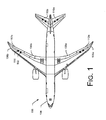
- Fig. 1 is a partially schematic, top view of an aircraft 100 having one or more control surface actuation systems 102 configured in accordance with an embodiment of the invention.
- the aircraft 100 includes a fuselage 104 and wings 106 (shown as first and second wings 106a and 106b) fixedly attached to the fuselage.
- Each wing 106 can include a number of movable control surfaces for controlling the aircraft 100 during flight.
- These control surfaces may include flaperons 108a, 108b, collectively referred to by reference numeral 108, elevators 110a, 110b, collectively referred to as 110, and ailerons 112a, 112b, collectively referred to as 112.
- the flight control actuation system 102 can extend or retract linear actuators to deflect the elevators up or down, which causes the aircraft to pitch nose up or down.
- the ailerons, rudder, flaperons, and spoilers may be deflected to generate the desired effects on the airplane.
- Fig. 2 is a schematic illustration of a flight control actuation system 102 which implements techniques to manage the output of a servo valve that drives the piston which, in turn, deflects a control surface, according to embodiments.
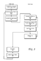
- Fig. 3 is a flowchart illustrating high-level operations of a method to manage the output of a servo valve, according to embodiments.
- the control system 102 comprises a first plurality of position feedback loops, generally indicated by reference numeral 270 to receive a plurality of commands representative of a desired piston position and to generate, from the plurality of commands, a plurality of position difference signals which represent a difference between a desired piston position and a current piston position, a plurality of amplifiers to generate, from the plurality of position difference signals, a corresponding plurality of magnetic flux target signals, a second plurality of magnetic flux feedback loops 272 to receive, from the plurality amplifiers, the plurality of magnetic flux target signals, wherein the magnetic flux target signals represent a desired magnetic flux in the servo valve 220, and to generate, from the plurality of magnetic flux target signals, a plurality of magnetic flux difference signals which represent a difference between a desired magnetic flux and a current magnetic flux, and an assembly to regulate the servo valve 220 using the magnetic flux difference signals.
- a first plurality of position feedback loops generally indicated by reference numeral 270 to receive a plurality of commands representative of a
- the system comprises flight control electronics 200, summing junctions 204a, 204b, 204c, amplifiers 206a, 206b, 206c, summing junctions 208a, 208b, 208c, amplifiers 210a, 210b, 210c, a two-stage electrohydraulic servo valve (EHSV) 220 that includes three electrically independent magnetic flux sensors 226, conditioners 228a, 228b, 228c, and a piston assembly 250 to that includes a position measuring assembly indicated LVDT 260 (linear variable differential transformer) comprising three electrically independent position sensors.
- EHSV electrohydraulic servo valve
- the EHSV 220 comprises a torque motor 222 and a spool valve 240.
- flight control electronics 200 may represent a "fly by wire" flight control electronics for an aircraft for an aircraft.
- flight control electronics 200 inputs three commands, which are identical under normal operating circumstances.
- the commands are input into summing junctions 204.
- the summing junctions 204 combine the commands with feedback signals 262 from the LVDT 260 and generate (operation 315) a signal representative of the difference between the current piston position as indicated by the LVDT 260 and the commands input by flight control electronics 200.
- the signals output from the summing junctions 204 are amplified by amplifiers 206 to generate (operation 320) a signal that is representative of a target level of magnetic flux in the torque motor 222 that corresponds to the difference between the current piston position as indicated by the LVDT 260 and the commands input by flight control electronics 200.
- the signals output from amplifiers 206 are input into summing junctions 208, which combines the signals with feedback signals from the magnetic flux sensors 226 and generate (operation 325) a signal representative of the difference between the current level of magnetic flux and the target level of magnetic flux in the torque motor 222.
- the signals output from summing junctions 208 are input into current amplifiers 210, which generate electric currents (operation 330) corresponding to the inputs and applies them to the servo coils 230a, 230b, 230c, collectively referred to by reference numeral 230 (operation 335).
- the application of current to coils 230 generates a magnetic flux in torque motor 222.
- Three magnetic flux sensors 226 measure (operation 340) the total amount of magnetic flux in motor 222, including the magnetic flux generated by permanent magnets 224a, 224b, collectively referred to by reference numeral 224.
- the outputs of the magnetic flux sensors are directed to conditioning units 228a, 228b, 228c, collectively referred to by reference numeral 228. Under normal operating conditions the outputs from the magnetic flux sensors 226 should be substantially nearly identical.
- the conditioning units 228 may implement operations to extract the useful component of the sensor output signal, e.g., by subtracting the magnetic flux contribution of the permanent magnets 224 and leaving the magnetic flux generated by the coils 230.
- the system 102 may be activated and the magnetic flux generated by the permanent magnets 224 may be measured when the coils 230 are not charged with current.
- the reading generated by the magnetic flux sensors 226 may be stored in a memory in a flight control electronics.
- the condition units 228 may subtract this value from the reading generated by the magnetic flux sensor 226 when the coils 230 are active to obtain a measurement of the magnetic flux generated by the coils 230.
- the output of the conditioning units 228 input into the summing junctions 206.
- Spool displacement causes the pressurized fluid supply line 238 to be connected to either chamber 254 via fluid line 246 or chamber 256 via fluid line 248, and non-pressurized return line 244 to be connected to the other chamber via the other fluid line, depending on the direction of spool displacement.
- the control system 102 provides a first position feedback loop indicated by reference numeral 270 which combines real-time feedback about the position of the piston 252 with the commands input from flight control electronics 200 via summing junctions 204.
- the difference signal generated by summing junctions 204 is amplified by amplifiers 206 and fed into the second feedback loop indicated by reference numeral 272 as the signal representing the desired total magnetic flux generated by the three coils.
- the magnetic flux sensor 226 measures the sum of the magnetic flux generated by the three torque motor coils 230 and the torque motor permanent magnet 224.
- the conditioners 228 each receive a signal representing this measurement and subtract the permanent magnet contribution, leaving the total magnetic flux generated by the three torque motor coils 230.
- the summing junctions 208 determine the difference between the signal representing the desired total magnetic flux input by amplifiers 206 and the signal representing the current total magnetic flux generated by the three torque motor coils 230, and the current amplifiers 210 output a current proportional thereto.
- the embodiment depicted in Fig. 2 provides three redundant signals.
- a failure in one or more of the signals in one of the lines of either feedback loop or in a device generating a signal representing the desired piston position causes an erroneous current to flow through a torque motor coil 230
- the resulting magnetic flux is sensed by the magnetic flux sensor 226 in the other two lines of the position control loops.
- the second feedback loop 272 has a quicker response time than the first feedback loop 270.
- the piston position and output force can be suppressed to an insignificant level.
- Fig. 2 illustrates three separate feedback loops for the piston position sensor and three separate feedback loops for the magnetic flux detector
- any number of independent loops i.e., dual, quadruple, etc.
- the control loops are fundamentally electrically independent as described, one skilled in the art will recognize that even if independence is partially breached through use of a common device, the fault suppression capability still remains for failures that may occur in the remainder of the control loops; in such a case, the common device should be monitored by a separate means to ensure proper operation.
- each amplifier 210 drives a single coil 230 in the embodiment depicted in Fig.
- each amplifier could drive two or more coils 230.
- a sensor could measure the total current flowing through coils 230 as a proxy for measuring the magnetic flux.
- this representation encompasses a variety of configurations, such as receiving one high-integrity command from one flight control electronics unit by a plurality of receivers or receiving a plurality of commands each from a separate flight control electronics unit.
- logic instructions as referred to herein relates to expressions which may be understood by one or more machines for performing one or more logical operations.
- logic instructions may comprise instructions which are interpretable by a processor compiler for executing one or more operations on one or more data objects.
- this is merely an example of machine-readable instructions and embodiments are not limited in this respect.
- a computer readable medium may comprise one or more storage devices for storing computer readable instructions or data.
- Such storage devices may comprise storage media such as, for example, optical, magnetic or semiconductor storage media.
- this is merely an example of a computer readable medium and embodiments are not limited in this respect.
- logic as referred to herein relates to structure for performing one or more logical operations.
- logic may comprise circuitry which provides one or more output signals based upon one or more input signals.
- Such circuitry may comprise a finite state machine which receives a digital input and provides a digital output, or circuitry which provides one or more analog output signals in response to one or more analog input signals.
- Such circuitry may be provided in an application specific integrated circuit (ASIC) or field programmable gate array (FPGA).
- ASIC application specific integrated circuit
- FPGA field programmable gate array
- logic may comprise machine-readable instructions stored in a memory in combination with processing circuitry to execute such machine-readable instructions.
- ASIC application specific integrated circuit
- FPGA field programmable gate array
- Various functional components of the system 102 may be implemented as logic instructions which may be executed on a general purpose processor or on a configurable flight control electronics.
- the summing junctions 204, 208, amplifiers 206, 210, and conditioners 228 may be implemented either as logic or as logic instructions.
- the logic instructions When executed on a processor, the logic instructions cause a processor to be programmed as a special-purpose machine that implements the described methods.
- the processor when configured by the logic instructions to execute the methods described herein, constitutes structure for performing the described methods.
- the methods described herein may be reduced to logic on, e.g., a field programmable gate array (FPGA), an application specific integrated circuit (ASIC) or the like.
- FPGA field programmable gate array
- ASIC application specific integrated circuit
- a computer program product may comprise logic instructions stored on a computer-readable medium which, when executed, configure a flight control electronics to detect whether a system management memory module is in a visible state, in response to a determination that system management memory is in a visible state, direct one or more system management memory input/output operations to a system management memory module, and in response to a determination that system management memory is in an invisible state, direct system management memory cache write back operations to the system management memory module and direct other system management memory input/output operations to another location in a system memory.
- an aircraft 100 having a fuselage 104 and wings 106 including at least one moveable control surface 108, 110, 112 coupled to at least one of the fuselage 104 and wings 106, a servo valve 220 coupled to a piston 252 which deflects the at least one moveable control surface 108, 110, 112, and a system 102 to manage the output of the servo valve 220.
- the system 102 may include a first plurality of feedback loops 270 to receive a plurality of commands representative of a desired piston 252 position and to generate, from the plurality of commands, a plurality of position difference signals 315 which represent a difference between a desired piston 252 position and a current piston 252 position, a plurality of amplifiers to generate, from the plurality of difference signals, a corresponding plurality of magnetic flux target signals 320, a second plurality of feedback loops 272 to receive, from the plurality of amplifiers, the plurality of magnetic flux target signals 320.
- the magnetic flux target signals 320 represent a desired magnetic flux measurement in the servo valve 220, and to generate, from the plurality of magnetic flux target signals 320, a plurality of magnetic flux difference signals 325 which represent a difference between a desired magnetic flux and a current magnetic flux, and an assembly to regulate the servo valve 220 using the magnetic flux difference signals 325.
- the first feedback loop 270 receives a plurality of commands from flight control electronics 200.
- the first plurality of feedback loops 270 combines the plurality of commands with feedback signals from a position sensor coupled to the piston 252.
- the second plurality of feedback loops 272 combines the plurality of magnetic flux target signals 320 with feedback signals from magnetic flux sensors 226 which measure magnetic flux 340.
- the assembly 102 to regulate the servo valve 220 includes a plurality of current amplifiers 206, 210 and coils 230 to generate a magnetic flux by inducing a level of coil current corresponding to the magnetic flux difference signal 325, a plurality of magnetic flux sensors 226 to measure the total magnetic flux in a servo torque motor 222 coupled to the servo valve, and a plurality of conditioners 228 to adjust the magnetic flux measurements by compensating for the magnetic flux contribution attributable to one or more permanent magnets in the servo torque motor 222.
- the airplane 100 may include logic to adjust a current flowing through a first flux control loop 270 in response to a change in a current flowing through a second flux control loop 272.
- the airplane 100 many include a hydraulic assembly to adjust a position of a piston 252 which regulates a control surface 108, 110, 112 in response to the magnetic flux generated in the servo valve 220.
- Coupled may mean that two or more elements are in direct physical or electrical contact.
- coupled may also mean that two or more elements may not be in direct contact with each other, but yet may still cooperate or interact with each other.
- the acts described may be implemented by a computer, flight control electronics, processor, programmable device, firmware, or any other suitable device, and may be based on instructions stored on one or more computer-readable media or otherwise stored or programmed into such devices (e.g. including transmitting computer-readable instructions in real time to such devices).
- the acts described above may represent computer instructions that, when executed by one or more processors, perform the recited operations.
- the computer-readable media can be any available media that can be accessed by a device to implement the instructions stored thereon.
Landscapes
- Engineering & Computer Science (AREA)
- Physics & Mathematics (AREA)
- Fluid Mechanics (AREA)
- Automation & Control Theory (AREA)
- Aviation & Aerospace Engineering (AREA)
- Feedback Control In General (AREA)
- Fluid-Pressure Circuits (AREA)
- Control Of Electric Motors In General (AREA)
Abstract
Description
- Aircraft include movable control surfaces for directional control in flight. Such control surfaces can include ailerons for roll control, elevators for pitch control, and rudders for yaw control.
- Hydraulic drive systems with linear actuators have been used for control surfaces and other control surface systems. Servo valves are used in hydraulic actuators to regulate the flow of hydraulic fluid, which then affects the position of a piston in the hydraulic actuator, and therefore the force of the actuator.
- The servo valve position may be controlled by the magnetic flux generated by one or more coils, and therefore may be referred to as an Electrohydraulic Servo Valve (EHSV) or a Direct Drive Valve (DDV). A failure which causes an erroneous level of current to flow through the coil may cause the actuator to move to a position or output a force that is not consistent with the expected output of the control system. Such a failure could cause the aircraft to deviate from a controlled course and/or cause structural damage to components of the aircraft. Accordingly, systems and methods to control servo systems which, in turn, manage control surfaces may find utility.
- Embodiments of systems and methods in accordance with the present disclosure may provide improved systems and methods to control drive surfaces in vehicles, e.g., aircraft. More specifically, embodiments described herein provide for redundancy and feedback control in servo control systems.
- In one embodiment, a method to manage the output of a servo valve, comprises receiving a plurality of commands representative of a desired piston position, generating, from the plurality of commands, a plurality of position difference signals which represent a difference between a desired piston position and a current piston position, generating from the plurality of position difference signals a plurality of magnetic flux target signals, wherein the magnetic flux target signals represent a desired magnetic flux measurement in the servo valve, generating, from the plurality of magnetic flux target signals, a plurality of magnetic flux difference signals which represent a difference between a desired magnetic flux measurement and a current magnetic flux measurement, and regulating the servo valve using the magnetic flux difference signals.
- In another embodiment, a system to manage the output of a servo valve, comprises a first plurality of feedback loops to receive a plurality of commands representative of a desired piston position and to generate, from the plurality of commands, a plurality of position difference signals which represent a difference between a desired piston position and a current piston position, a plurality of amplifiers to generate, from the plurality of position difference signals, a corresponding plurality of magnetic flux target signals, a second plurality of feedback loops to receive, from the plurality of amplifiers, the plurality of magnetic flux target signals, wherein the magnetic flux target signals represent a desired magnetic flux measurement in the servo valve, and to generate, from the plurality of magnetic flux target signals, a plurality of magnetic flux difference signals which represent a difference between a desired magnetic flux and a current magnetic flux; and an assembly to regulate the servo valve using the plurality of magnetic flux difference signals.
- In yet another embodiment, an aircraft comprises a fuselage and wings, at least one moveable control surface coupled to at least one of the fuselage and wings, a servo valve coupled to a piston which deflects the at least one moveable control surface and a system to manage the output of the servo valve. The system comprises a first plurality of feedback loops to receive a plurality of commands representative of a desired piston position and to generate, from the plurality of commands, a plurality of position difference signals which represent a difference between a desired piston position and a current piston position, a plurality of amplifiers to generate, from the plurality of position difference signals, a corresponding plurality of magnetic flux target signals, a second plurality of feedback loops to receive, from the plurality of amplifiers, the plurality of magnetic flux target signals, wherein the magnetic flux target signals represent a desired magnetic flux measurement in the servo valve, and to generate, from the plurality of magnetic flux target signals, a plurality of magnetic flux difference signals which represent a difference between a desired magnetic flux and a current magnetic flux, and an assembly to regulate the servo valve using the plurality of magnetic flux difference signals.
- Further areas of applicability will become apparent from the description provided herein. It should be understood that the description and specific examples are intended for purposes of illustration only and are not intended to limit the scope of the present disclosure
- Embodiments of methods and systems in accordance with the teachings of the present disclosure are described in detail below with reference to the following drawings.
-
Fig. 1 is a partially schematic, top view of an aircraft having a control system in accordance with embodiments. -
Fig. 2 is a schematic illustration of a system to manage the output of a servo valve, according to embodiments. -
Fig. 3 is a flowchart illustrating high-level operations of a method to manage the output of a servo valve, according to embodiments. - Systems and methods to control servo drives which may be used, e.g., to manage control surfaces in aircraft are described herein. Specific details of certain embodiments are set forth in the following description and in
Figs. 1-3 to provide a thorough understanding of such embodiments. One skilled in the art will understand, however, that alternate embodiments may be practiced without several of the details described in the following description. -
Fig. 1 is a partially schematic, top view of anaircraft 100 having one or more controlsurface actuation systems 102 configured in accordance with an embodiment of the invention. In one aspect of this embodiment, theaircraft 100 includes afuselage 104 and wings 106 (shown as first andsecond wings aircraft 100 during flight. These control surfaces may includeflaperons elevators ailerons - In operation, the flight
control actuation system 102 can extend or retract linear actuators to deflect the elevators up or down, which causes the aircraft to pitch nose up or down. Similarly, the ailerons, rudder, flaperons, and spoilers, may be deflected to generate the desired effects on the airplane. -
Fig. 2 is a schematic illustration of a flightcontrol actuation system 102 which implements techniques to manage the output of a servo valve that drives the piston which, in turn, deflects a control surface, according to embodiments.Fig. 3 is a flowchart illustrating high-level operations of a method to manage the output of a servo valve, according to embodiments. - Referring to
Figs. 2-3 , in some embodiments thecontrol system 102 comprises a first plurality of position feedback loops, generally indicated byreference numeral 270 to receive a plurality of commands representative of a desired piston position and to generate, from the plurality of commands, a plurality of position difference signals which represent a difference between a desired piston position and a current piston position, a plurality of amplifiers to generate, from the plurality of position difference signals, a corresponding plurality of magnetic flux target signals, a second plurality of magneticflux feedback loops 272 to receive, from the plurality amplifiers, the plurality of magnetic flux target signals, wherein the magnetic flux target signals represent a desired magnetic flux in theservo valve 220, and to generate, from the plurality of magnetic flux target signals, a plurality of magnetic flux difference signals which represent a difference between a desired magnetic flux and a current magnetic flux, and an assembly to regulate theservo valve 220 using the magnetic flux difference signals. - In the embodiment depicted in
Fig. 2 the system comprisesflight control electronics 200,summing junctions amplifiers summing junctions amplifiers magnetic flux sensors 226,conditioners torque motor 222 and aspool valve 240. - In the embodiment depicted in
Fig. 2 the system receives three commands from a flight control electronics 200 (operation 310). By way of example,flight control electronics 200 may represent a "fly by wire" flight control electronics for an aircraft for an aircraft. In the embodiment depicted inFig. 2 theflight control electronics 200 inputs three commands, which are identical under normal operating circumstances. The commands are input into summing junctions 204. The summing junctions 204 combine the commands with feedback signals 262 from theLVDT 260 and generate (operation 315) a signal representative of the difference between the current piston position as indicated by theLVDT 260 and the commands input byflight control electronics 200. - The signals output from the summing junctions 204 are amplified by amplifiers 206 to generate (operation 320) a signal that is representative of a target level of magnetic flux in the
torque motor 222 that corresponds to the difference between the current piston position as indicated by theLVDT 260 and the commands input byflight control electronics 200. The signals output from amplifiers 206 are input into summing junctions 208, which combines the signals with feedback signals from themagnetic flux sensors 226 and generate (operation 325) a signal representative of the difference between the current level of magnetic flux and the target level of magnetic flux in thetorque motor 222. - The signals output from summing junctions 208 are input into current amplifiers 210, which generate electric currents (operation 330) corresponding to the inputs and applies them to the
servo coils torque motor 222. Threemagnetic flux sensors 226 measure (operation 340) the total amount of magnetic flux inmotor 222, including the magnetic flux generated bypermanent magnets - The outputs of the magnetic flux sensors are directed to
conditioning units magnetic flux sensors 226 should be substantially nearly identical. The conditioning units 228 may implement operations to extract the useful component of the sensor output signal, e.g., by subtracting the magnetic flux contribution of the permanent magnets 224 and leaving the magnetic flux generated by the coils 230. In some embodiments thesystem 102 may be activated and the magnetic flux generated by the permanent magnets 224 may be measured when the coils 230 are not charged with current. The reading generated by themagnetic flux sensors 226 may be stored in a memory in a flight control electronics. The condition units 228 may subtract this value from the reading generated by themagnetic flux sensor 226 when the coils 230 are active to obtain a measurement of the magnetic flux generated by the coils 230. The output of the conditioning units 228 input into the summing junctions 206. - Electrical current in the coils 230 creates a magnetic flux, which generates a torque applied on the armature 232. The torque thus applied causes the armature and thus the
pipe 234 to deflect, resulting in the fluid pressure in one end of thespool valve 240 to rise, while that in the other end to fall. The pressure difference thus created causes thespool 241 to slide in the direction away from the higher-pressure side and towards the low-pressure side. The displacement of thespool 241 deflects thefeedback spring 243 and creates a torque applied on thepipe 234 in the direction opposing the torque created by the magnetic flux. The spool stops where the torque created by the magnetic flux and the deflection of thefeedback spring 243 are balanced. Spool displacement causes the pressurizedfluid supply line 238 to be connected to eitherchamber 254 viafluid line 246 orchamber 256 viafluid line 248, andnon-pressurized return line 244 to be connected to the other chamber via the other fluid line, depending on the direction of spool displacement. - Thus, when pressurized fluid is directed into
chamber 254 byspool valve 240 thepiston 252 is moved in the direction ofLVDT 260 to deflect a control surface in one direction, e.g., trailing-edge down. By contrast, when pressurized fluid is directed into thechamber 256 byspool valve 240 thepiston 252 is moved in the opposite direction to deflect a control surface in the other direction, e.g., trailing edge up. The LVDT measures the piston position (operation 350) and generates three output signals which indicate the distance that thepiston 252 is displaced. The output signals are provided as feedback to the summing junctions 204. - Thus, the
control system 102 provides a first position feedback loop indicated byreference numeral 270 which combines real-time feedback about the position of thepiston 252 with the commands input fromflight control electronics 200 via summing junctions 204. The difference signal generated by summing junctions 204 is amplified by amplifiers 206 and fed into the second feedback loop indicated byreference numeral 272 as the signal representing the desired total magnetic flux generated by the three coils. Within the second magneticflux feedback loop 272, themagnetic flux sensor 226 measures the sum of the magnetic flux generated by the three torque motor coils 230 and the torque motor permanent magnet 224. The conditioners 228 each receive a signal representing this measurement and subtract the permanent magnet contribution, leaving the total magnetic flux generated by the three torque motor coils 230. The summing junctions 208 determine the difference between the signal representing the desired total magnetic flux input by amplifiers 206 and the signal representing the current total magnetic flux generated by the three torque motor coils 230, and the current amplifiers 210 output a current proportional thereto. - The embodiment depicted in
Fig. 2 provides three redundant signals. Thus, when a failure in one or more of the signals in one of the lines of either feedback loop or in a device generating a signal representing the desired piston position causes an erroneous current to flow through a torque motor coil 230, the resulting magnetic flux is sensed by themagnetic flux sensor 226 in the other two lines of the position control loops. This, in turn, causes a current to flow in the other two torque motor coils and create a magnetic flux opposing that which is created by the erroneous current. Further, thesecond feedback loop 272 has a quicker response time than thefirst feedback loop 270. Thus, the piston position and output force can be suppressed to an insignificant level. - One skilled in the art will recognize that various alternate embodiments may be implemented. By way of example, although the embodiment depicted in
Fig. 2 illustrates three separate feedback loops for the piston position sensor and three separate feedback loops for the magnetic flux detector, any number of independent loops (i.e., dual, quadruple, etc.) may be used. Further, while the control loops are fundamentally electrically independent as described, one skilled in the art will recognize that even if independence is partially breached through use of a common device, the fault suppression capability still remains for failures that may occur in the remainder of the control loops; in such a case, the common device should be monitored by a separate means to ensure proper operation. Still further, while each amplifier 210 drives a single coil 230 in the embodiment depicted inFig. 2 , one skilled in the art will recognize that each amplifier could drive two or more coils 230. Still further, one skilled in the art will recognize that a sensor could measure the total current flowing through coils 230 as a proxy for measuring the magnetic flux. Still further, although the embodiment depicted inFig. 2 illustrates a system receiving three commands from a flight control electronics 200 (operation 310), one skilled in the art will recognize this representation encompasses a variety of configurations, such as receiving one high-integrity command from one flight control electronics unit by a plurality of receivers or receiving a plurality of commands each from a separate flight control electronics unit. - The terms "logic instructions" as referred to herein relates to expressions which may be understood by one or more machines for performing one or more logical operations. For example, logic instructions may comprise instructions which are interpretable by a processor compiler for executing one or more operations on one or more data objects. However, this is merely an example of machine-readable instructions and embodiments are not limited in this respect.
- The terms "computer readable medium" as referred to herein relates to media capable of maintaining expressions which are perceivable by one or more machines. For example, a computer readable medium may comprise one or more storage devices for storing computer readable instructions or data. Such storage devices may comprise storage media such as, for example, optical, magnetic or semiconductor storage media. However, this is merely an example of a computer readable medium and embodiments are not limited in this respect.
- The term "logic" as referred to herein relates to structure for performing one or more logical operations. For example, logic may comprise circuitry which provides one or more output signals based upon one or more input signals. Such circuitry may comprise a finite state machine which receives a digital input and provides a digital output, or circuitry which provides one or more analog output signals in response to one or more analog input signals. Such circuitry may be provided in an application specific integrated circuit (ASIC) or field programmable gate array (FPGA). Also, logic may comprise machine-readable instructions stored in a memory in combination with processing circuitry to execute such machine-readable instructions. However, these are merely examples of structures which may provide logic and embodiments are not limited in this respect.
- Various functional components of the
system 102 may be implemented as logic instructions which may be executed on a general purpose processor or on a configurable flight control electronics. By way of example, in some embodiments the summing junctions 204, 208, amplifiers 206, 210, and conditioners 228 may be implemented either as logic or as logic instructions. When executed on a processor, the logic instructions cause a processor to be programmed as a special-purpose machine that implements the described methods. The processor, when configured by the logic instructions to execute the methods described herein, constitutes structure for performing the described methods. Alternatively, the methods described herein may be reduced to logic on, e.g., a field programmable gate array (FPGA), an application specific integrated circuit (ASIC) or the like. - For example, in some embodiments a computer program product may comprise logic instructions stored on a computer-readable medium which, when executed, configure a flight control electronics to detect whether a system management memory module is in a visible state, in response to a determination that system management memory is in a visible state, direct one or more system management memory input/output operations to a system management memory module, and in response to a determination that system management memory is in an invisible state, direct system management memory cache write back operations to the system management memory module and direct other system management memory input/output operations to another location in a system memory.
- As illustrated in the above disclosure including
Figures 1-3 , anaircraft 100 is disclosed having afuselage 104 and wings 106 including at least one moveable control surface 108, 110, 112 coupled to at least one of thefuselage 104 and wings 106, aservo valve 220 coupled to apiston 252 which deflects the at least one moveable control surface 108, 110, 112, and asystem 102 to manage the output of theservo valve 220. Thesystem 102 may include a first plurality offeedback loops 270 to receive a plurality of commands representative of a desiredpiston 252 position and to generate, from the plurality of commands, a plurality of position difference signals 315 which represent a difference between a desiredpiston 252 position and acurrent piston 252 position, a plurality of amplifiers to generate, from the plurality of difference signals, a corresponding plurality of magnetic flux target signals 320, a second plurality offeedback loops 272 to receive, from the plurality of amplifiers, the plurality of magnetic flux target signals 320. In one instance, the magnetic flux target signals 320 represent a desired magnetic flux measurement in theservo valve 220, and to generate, from the plurality of magnetic flux target signals 320, a plurality of magnetic flux difference signals 325 which represent a difference between a desired magnetic flux and a current magnetic flux, and an assembly to regulate theservo valve 220 using the magnetic flux difference signals 325. In one variant, thefirst feedback loop 270 receives a plurality of commands fromflight control electronics 200. In yet another variant, the first plurality offeedback loops 270 combines the plurality of commands with feedback signals from a position sensor coupled to thepiston 252. In yet another variant, the second plurality offeedback loops 272 combines the plurality of magnetic flux target signals 320 with feedback signals frommagnetic flux sensors 226 which measuremagnetic flux 340. In yet another instance, theassembly 102 to regulate theservo valve 220 includes a plurality of current amplifiers 206, 210 and coils 230 to generate a magnetic flux by inducing a level of coil current corresponding to the magneticflux difference signal 325, a plurality ofmagnetic flux sensors 226 to measure the total magnetic flux in aservo torque motor 222 coupled to the servo valve, and a plurality of conditioners 228 to adjust the magnetic flux measurements by compensating for the magnetic flux contribution attributable to one or more permanent magnets in theservo torque motor 222. In yet another variant, theairplane 100 may include logic to adjust a current flowing through a firstflux control loop 270 in response to a change in a current flowing through a secondflux control loop 272. In yet another variant, theairplane 100 many include a hydraulic assembly to adjust a position of apiston 252 which regulates a control surface 108, 110, 112 in response to the magnetic flux generated in theservo valve 220. - In the description and claims, the terms coupled and connected, along with their derivatives, may be used. In particular embodiments, connected may be used to indicate that two or more elements are in direct physical or electrical contact with each other. Coupled may mean that two or more elements are in direct physical or electrical contact. However, coupled may also mean that two or more elements may not be in direct contact with each other, but yet may still cooperate or interact with each other.
- Reference in the specification to "one embodiment" or "some embodiments" means that a particular feature, structure, or characteristic described in connection with the embodiment is included in at least an implementation. The appearances of the phrase "in one embodiment" in various places in the specification may or may not be all referring to the same embodiment. In the foregoing discussion, specific implementations of exemplary processes have been described, however, it should be understood that in alternate implementations, certain acts need not be performed in the order described above. In alternate embodiments, some acts may be modified, performed in a different order, or may be omitted entirely, depending on the circumstances. Moreover, in various alternate implementations, the acts described may be implemented by a computer, flight control electronics, processor, programmable device, firmware, or any other suitable device, and may be based on instructions stored on one or more computer-readable media or otherwise stored or programmed into such devices (e.g. including transmitting computer-readable instructions in real time to such devices). In the context of software, the acts described above may represent computer instructions that, when executed by one or more processors, perform the recited operations. In the event that computer-readable media are used, the computer-readable media can be any available media that can be accessed by a device to implement the instructions stored thereon.
- While various embodiments have been described, those skilled in the art will recognize modifications or variations which might be made without departing from the present disclosure. The examples illustrate the various embodiments and are not intended to limit the present disclosure. Therefore, the description and claims should be interpreted liberally with only such limitation as is necessary in view of the pertinent prior art.
Claims (15)
- A method to manage an output of a servo valve (220), comprising:receiving a plurality of commands representative of a desired piston (252) position;generating, from the plurality of commands, a plurality of position difference signals (315) which represent a difference between a desired piston (252) position and a current piston (252) position;generating, from the plurality of position difference signals (315), a plurality of magnetic flux target signals (320), wherein the magnetic flux target signals (320) represent a desired magnetic flux measurement in the servo valve (220);generating, from the plurality of magnetic flux target signals (320), a plurality of magnetic flux difference signals (325) which represent a difference between a desired magnetic flux measurement and a current magnetic flux measurement; andregulating the servo valve (220) using the magnetic flux difference signals.
- The method of claim 1, wherein receiving a plurality of commands representative of a desired piston (252) position comprises receiving a plurality of commands from flight control electronics (200).
- The method of any of the claims 1-2, wherein generating, from the plurality of commands, a plurality of position difference signals (315) which represent a difference between a desired piston (252) position and a current piston (252) position comprises combining the plurality of commands with feedback signals from a position sensors coupled to the piston (252).
- The method of any of claims 1-3, wherein generating, from the plurality of difference signals (315), a plurality of magnetic flux target signals (320), wherein the magnetic flux target signals (320) represent a desired magnetic flux measurement in the servo valve (220), comprises amplifying the plurality of position difference signals (315).
- The method of any of claims 1-4, wherein generating, from the plurality of magnetic flux target signals (320), a plurality of magnetic flux difference signals (325) which represent a difference between a desired magnetic flux measurement and a current magnetic flux measurement comprises combining the plurality of magnetic flux target signals with feedback signals from magnetic flux sensors (226) which measure magnetic flux.
- The method of any of claims 1-5, wherein regulating the servo valve (220) using the magnetic flux difference signals comprises:generating a magnetic flux by inducing a level of electrical coil current corresponding to the magnetic flux difference signals (325);measuring a total magnetic flux in a servo torque motor (222) coupled to the servo valve (220);adjusting the magnetic flux measurement by compensating for a magnetic flux contribution attributable to one or more permanent magnets in the servo torque motor (222).
- The method of any of claims 1-6, wherein regulating the servo valve (220) using the flux target signals (320) comprises adjusting a current flowing through a first flux control loop (270) in response to a change in a current flowing through a second flux control loop (272).
- A system to manage an output of a servo valve (220), comprising:a first plurality of feedback loops (270) to receive a plurality of commands representative of a desired piston (252) position and to generate, from the plurality of commands, a plurality of position difference signals (315) which represent a difference between a desired piston (252) position and a current piston (252) position;a plurality of amplifiers (206, 210) to generate, from the plurality of difference signals (315), a corresponding plurality of magnetic flux target signals (320);a second plurality of feedback loops (272) to receive, from the plurality of amplifiers (206, 210), the plurality of magnetic flux target signals (320), wherein the magnetic flux target signals (320) represent a desired magnetic flux measurement in the servo valve (220), and to generate, from the plurality of magnetic flux target signals (320), a plurality of magnetic flux difference signals (325) which represent a difference between a desired magnetic flux measurement and a current magnetic flux measurement; andan assembly to regulate the servo valve (220) using the plurality of magnetic flux difference signals (325).
- The system of claim 8, wherein the first plurality of feedback loops (270) receives a plurality of commands from a flight control electronics (200).
- The system of any of claims 8-9, wherein the first plurality of feedback loops (270) combines the plurality of commands with feedback signals from a position sensor coupled to the piston (252).
- The system of any of claims 8-10, wherein the second plurality of feedback loops (272) combines the plurality of magnetic flux target signals (320) with feedback signals from magnetic flux sensors (226) which measure magnetic flux (340).
- The system of any of claims 8-11, wherein the assembly to regulate the servo valve (220) comprises:a plurality of current amplifiers (206, 210) and coils to generate a magnetic flux by inducing a level of coil current corresponding to the magnetic flux difference signal (325);a plurality of magnetic flux sensors (226) to measure a total magnetic flux in a servo torque motor (222) coupled to the servo valve (220);a plurality of conditioners (228) to adjust the magnetic flux measurements by compensating for a magnetic flux contribution attributable to one or more permanent magnets in the servo torque motor (222).
- The system of any of claims 8-12, further comprising logic to adjust a current flowing through a first flux control loop (270) in response to a change in a current flowing through a second flux control loop (272).
- The system of any of claims 8-13, further comprising:a hydraulic assembly to adjust a position of a piston (252) which regulates a control surface in response to the magnetic flux generated in the servo valve (220).
- A system arranged to carry out the steps of the method according to any of claims 1-7.
Applications Claiming Priority (1)
| Application Number | Priority Date | Filing Date | Title |
|---|---|---|---|
| US13/115,909 US8620522B2 (en) | 2011-05-25 | 2011-05-25 | Suppressing electrical failure effects in servo control systems |
Publications (3)
| Publication Number | Publication Date |
|---|---|
| EP2527248A2 true EP2527248A2 (en) | 2012-11-28 |
| EP2527248A3 EP2527248A3 (en) | 2017-11-08 |
| EP2527248B1 EP2527248B1 (en) | 2018-11-14 |
Family
ID=46207862
Family Applications (1)
| Application Number | Title | Priority Date | Filing Date |
|---|---|---|---|
| EP12169236.2A Active EP2527248B1 (en) | 2011-05-25 | 2012-05-24 | Suppressing electrical failure effects in servo control systems |
Country Status (3)
| Country | Link |
|---|---|
| US (1) | US8620522B2 (en) |
| EP (1) | EP2527248B1 (en) |
| ES (1) | ES2710291T3 (en) |
Cited By (5)
| Publication number | Priority date | Publication date | Assignee | Title |
|---|---|---|---|---|
| CN103195767A (en) * | 2013-04-12 | 2013-07-10 | 长春航空液压控制有限公司 | Direct-acting adjusting type torque motor flow servo valve |
| CN105523174A (en) * | 2014-09-28 | 2016-04-27 | 中国航空工业集团公司西安飞机设计研究所 | Integrated control valve assembly-actuating cylinder separated hydraulic servo actuator |
| WO2017151493A1 (en) * | 2016-03-03 | 2017-09-08 | Woodward, Inc. | Redundant vehicle control systems |
| EP3306803A1 (en) * | 2016-10-10 | 2018-04-11 | The Boeing Company | Multiple electromechanical actuator control system |
| US11671035B2 (en) | 2019-02-21 | 2023-06-06 | Siemens Aktiengesellschaft | Method for operating a system comprising at least two mechanically coupled asynchronous motors, computer program containing an implementation of the method and system operating in accordance with the method |
Families Citing this family (6)
| Publication number | Priority date | Publication date | Assignee | Title |
|---|---|---|---|---|
| JP5426037B2 (en) * | 2010-11-25 | 2014-02-26 | 株式会社島津製作所 | Hydraulic cylinder system |
| US8683860B2 (en) | 2011-10-28 | 2014-04-01 | The Boeing Company | Flow-gain based hydraulic actuator leakage test |
| US9117579B2 (en) * | 2013-07-16 | 2015-08-25 | The Boeing Company | Redundant current-sum feedback actuator |
| CN107949982A (en) * | 2015-08-08 | 2018-04-20 | 日本电产株式会社 | Motor controller and motor system |
| US10788577B2 (en) | 2017-12-29 | 2020-09-29 | Texas Instruments Incorporated | Time of flight absolute position measurement |
| CN116991147B (en) * | 2023-09-26 | 2024-01-19 | 西安热工研究院有限公司 | Servo card LVDT calibration value calibration method, system, servo card and storage medium |
Family Cites Families (9)
| Publication number | Priority date | Publication date | Assignee | Title |
|---|---|---|---|---|
| US4807516A (en) | 1987-04-23 | 1989-02-28 | The Boeing Company | Flight control system employing three controllers operating a dual actuator |
| US5806805A (en) * | 1996-08-07 | 1998-09-15 | The Boeing Company | Fault tolerant actuation system for flight control actuators |
| US6731083B2 (en) * | 1998-06-02 | 2004-05-04 | Switched Reluctance Drives, Ltd. | Flux feedback control system |
| US6799739B1 (en) | 2003-11-24 | 2004-10-05 | The Boeing Company | Aircraft control surface drive system and associated methods |
| US7338017B2 (en) | 2004-04-15 | 2008-03-04 | The Boeing Company | Methods and apparatus for vibration and buffet suppression |
| US7789345B2 (en) | 2005-03-03 | 2010-09-07 | Nabtesco Corporation | Actuator control apparatus |
| US7600715B2 (en) | 2005-03-25 | 2009-10-13 | Nabtesco Corporation | Local backup hydraulic actuator for aircraft control systems |
| US7637458B2 (en) | 2005-06-08 | 2009-12-29 | The Boeing Company | Systems and methods for providing back-up hydraulic power for aircraft, including tanker aircraft |
| WO2007134287A1 (en) * | 2006-05-12 | 2007-11-22 | Parker-Hannifin Corporation | Displacement measurement device |
-
2011
- 2011-05-25 US US13/115,909 patent/US8620522B2/en not_active Expired - Fee Related
-
2012
- 2012-05-24 EP EP12169236.2A patent/EP2527248B1/en active Active
- 2012-05-24 ES ES12169236T patent/ES2710291T3/en active Active
Non-Patent Citations (1)
| Title |
|---|
| None |
Cited By (9)
| Publication number | Priority date | Publication date | Assignee | Title |
|---|---|---|---|---|
| CN103195767A (en) * | 2013-04-12 | 2013-07-10 | 长春航空液压控制有限公司 | Direct-acting adjusting type torque motor flow servo valve |
| CN105523174A (en) * | 2014-09-28 | 2016-04-27 | 中国航空工业集团公司西安飞机设计研究所 | Integrated control valve assembly-actuating cylinder separated hydraulic servo actuator |
| CN105523174B (en) * | 2014-09-28 | 2017-10-31 | 中国航空工业集团公司西安飞机设计研究所 | A hydraulic servo actuator with separated door cylinder |
| WO2017151493A1 (en) * | 2016-03-03 | 2017-09-08 | Woodward, Inc. | Redundant vehicle control systems |
| US10969035B2 (en) | 2016-03-03 | 2021-04-06 | Woodward, Inc. | Redundant vehicle control systems |
| US11933420B2 (en) | 2016-03-03 | 2024-03-19 | Woodward, Inc. | Redundant vehicle control systems |
| EP3306803A1 (en) * | 2016-10-10 | 2018-04-11 | The Boeing Company | Multiple electromechanical actuator control system |
| US10483880B2 (en) | 2016-10-10 | 2019-11-19 | The Boeing Company | Multiple electromechanical actuator control system |
| US11671035B2 (en) | 2019-02-21 | 2023-06-06 | Siemens Aktiengesellschaft | Method for operating a system comprising at least two mechanically coupled asynchronous motors, computer program containing an implementation of the method and system operating in accordance with the method |
Also Published As
| Publication number | Publication date |
|---|---|
| EP2527248A3 (en) | 2017-11-08 |
| US8620522B2 (en) | 2013-12-31 |
| EP2527248B1 (en) | 2018-11-14 |
| US20120303210A1 (en) | 2012-11-29 |
| ES2710291T3 (en) | 2019-04-24 |
Similar Documents
| Publication | Publication Date | Title |
|---|---|---|
| EP2527248B1 (en) | Suppressing electrical failure effects in servo control systems | |
| US9548152B2 (en) | Redundant current-sum feedback actuator | |
| US8534599B2 (en) | Redundant two stage electro-hydraulic servo actuator control | |
| US4671166A (en) | Electro-hydraulic actuator systems | |
| CN105035309B (en) | Actuator system for aircraft control surfaces | |
| EP3081480B1 (en) | Electro-hydraulic servo valve control system | |
| US10384764B2 (en) | System for actuating a control surface of an aircraft | |
| JP5498887B2 (en) | Damping test method, control device, hydraulic system, and program | |
| US11391384B2 (en) | Hydraulic actuator force fight mitigation mechanism | |
| US10651364B2 (en) | Servo valve with asymmetrical redundant piezoelectric actuator | |
| US10501201B2 (en) | Aerodynamic control surface movement monitoring system for aircraft | |
| JP7555740B2 (en) | Spool position estimation device, hydraulic actuator device for aircraft, spool position estimation method, and spool position estimation program | |
| CA2851869C (en) | Redundant current-sum feedback actuator | |
| CN107165889A (en) | The system and method calibrated for electro-hydraulic valve | |
| US10048090B2 (en) | Direct position measurement for aircraft flight control surfaces | |
| CN104019082B (en) | Detect the method for servovalve fault and the servovalve of application the method | |
| US20240404739A1 (en) | Method for adjusting a valve | |
| US11994117B2 (en) | Variable positive displacement pump actuator systems | |
| Jacazio et al. | A dual-duplex electrohydraulic system for the fly-by-wire control of a helicopter main rotor |
Legal Events
| Date | Code | Title | Description |
|---|---|---|---|
| PUAI | Public reference made under article 153(3) epc to a published international application that has entered the european phase |
Free format text: ORIGINAL CODE: 0009012 |
|
| 17P | Request for examination filed |
Effective date: 20120524 |
|
| AK | Designated contracting states |
Kind code of ref document: A2 Designated state(s): AL AT BE BG CH CY CZ DE DK EE ES FI FR GB GR HR HU IE IS IT LI LT LU LV MC MK MT NL NO PL PT RO RS SE SI SK SM TR |
|
| AX | Request for extension of the european patent |
Extension state: BA ME |
|
| PUAL | Search report despatched |
Free format text: ORIGINAL CODE: 0009013 |
|
| AK | Designated contracting states |
Kind code of ref document: A3 Designated state(s): AL AT BE BG CH CY CZ DE DK EE ES FI FR GB GR HR HU IE IS IT LI LT LU LV MC MK MT NL NO PL PT RO RS SE SI SK SM TR |
|
| AX | Request for extension of the european patent |
Extension state: BA ME |
|
| RIC1 | Information provided on ipc code assigned before grant |
Ipc: B64C 13/50 20060101ALI20171005BHEP Ipc: B64C 13/40 20060101AFI20171005BHEP |
|
| GRAP | Despatch of communication of intention to grant a patent |
Free format text: ORIGINAL CODE: EPIDOSNIGR1 |
|
| STAA | Information on the status of an ep patent application or granted ep patent |
Free format text: STATUS: GRANT OF PATENT IS INTENDED |
|
| INTG | Intention to grant announced |
Effective date: 20180612 |
|
| GRAS | Grant fee paid |
Free format text: ORIGINAL CODE: EPIDOSNIGR3 |
|
| GRAA | (expected) grant |
Free format text: ORIGINAL CODE: 0009210 |
|
| STAA | Information on the status of an ep patent application or granted ep patent |
Free format text: STATUS: THE PATENT HAS BEEN GRANTED |
|
| AK | Designated contracting states |
Kind code of ref document: B1 Designated state(s): AL AT BE BG CH CY CZ DE DK EE ES FI FR GB GR HR HU IE IS IT LI LT LU LV MC MK MT NL NO PL PT RO RS SE SI SK SM TR |
|
| REG | Reference to a national code |
Ref country code: CH Ref legal event code: EP Ref country code: AT Ref legal event code: REF Ref document number: 1064480 Country of ref document: AT Kind code of ref document: T Effective date: 20181115 |
|
| REG | Reference to a national code |
Ref country code: DE Ref legal event code: R096 Ref document number: 602012053388 Country of ref document: DE |
|
| REG | Reference to a national code |
Ref country code: IE Ref legal event code: FG4D |
|
| REG | Reference to a national code |
Ref country code: NL Ref legal event code: MP Effective date: 20181114 |
|
| REG | Reference to a national code |
Ref country code: LT Ref legal event code: MG4D |
|
| REG | Reference to a national code |
Ref country code: AT Ref legal event code: MK05 Ref document number: 1064480 Country of ref document: AT Kind code of ref document: T Effective date: 20181114 |
|
| REG | Reference to a national code |
Ref country code: ES Ref legal event code: FG2A Ref document number: 2710291 Country of ref document: ES Kind code of ref document: T3 Effective date: 20190424 |
|
| PG25 | Lapsed in a contracting state [announced via postgrant information from national office to epo] |
Ref country code: FI Free format text: LAPSE BECAUSE OF FAILURE TO SUBMIT A TRANSLATION OF THE DESCRIPTION OR TO PAY THE FEE WITHIN THE PRESCRIBED TIME-LIMIT Effective date: 20181114 Ref country code: LV Free format text: LAPSE BECAUSE OF FAILURE TO SUBMIT A TRANSLATION OF THE DESCRIPTION OR TO PAY THE FEE WITHIN THE PRESCRIBED TIME-LIMIT Effective date: 20181114 Ref country code: NO Free format text: LAPSE BECAUSE OF FAILURE TO SUBMIT A TRANSLATION OF THE DESCRIPTION OR TO PAY THE FEE WITHIN THE PRESCRIBED TIME-LIMIT Effective date: 20190214 Ref country code: AT Free format text: LAPSE BECAUSE OF FAILURE TO SUBMIT A TRANSLATION OF THE DESCRIPTION OR TO PAY THE FEE WITHIN THE PRESCRIBED TIME-LIMIT Effective date: 20181114 Ref country code: HR Free format text: LAPSE BECAUSE OF FAILURE TO SUBMIT A TRANSLATION OF THE DESCRIPTION OR TO PAY THE FEE WITHIN THE PRESCRIBED TIME-LIMIT Effective date: 20181114 Ref country code: IS Free format text: LAPSE BECAUSE OF FAILURE TO SUBMIT A TRANSLATION OF THE DESCRIPTION OR TO PAY THE FEE WITHIN THE PRESCRIBED TIME-LIMIT Effective date: 20190314 Ref country code: BG Free format text: LAPSE BECAUSE OF FAILURE TO SUBMIT A TRANSLATION OF THE DESCRIPTION OR TO PAY THE FEE WITHIN THE PRESCRIBED TIME-LIMIT Effective date: 20190214 Ref country code: LT Free format text: LAPSE BECAUSE OF FAILURE TO SUBMIT A TRANSLATION OF THE DESCRIPTION OR TO PAY THE FEE WITHIN THE PRESCRIBED TIME-LIMIT Effective date: 20181114 |
|
| PG25 | Lapsed in a contracting state [announced via postgrant information from national office to epo] |
Ref country code: AL Free format text: LAPSE BECAUSE OF FAILURE TO SUBMIT A TRANSLATION OF THE DESCRIPTION OR TO PAY THE FEE WITHIN THE PRESCRIBED TIME-LIMIT Effective date: 20181114 Ref country code: PT Free format text: LAPSE BECAUSE OF FAILURE TO SUBMIT A TRANSLATION OF THE DESCRIPTION OR TO PAY THE FEE WITHIN THE PRESCRIBED TIME-LIMIT Effective date: 20190314 Ref country code: NL Free format text: LAPSE BECAUSE OF FAILURE TO SUBMIT A TRANSLATION OF THE DESCRIPTION OR TO PAY THE FEE WITHIN THE PRESCRIBED TIME-LIMIT Effective date: 20181114 Ref country code: GR Free format text: LAPSE BECAUSE OF FAILURE TO SUBMIT A TRANSLATION OF THE DESCRIPTION OR TO PAY THE FEE WITHIN THE PRESCRIBED TIME-LIMIT Effective date: 20190215 Ref country code: RS Free format text: LAPSE BECAUSE OF FAILURE TO SUBMIT A TRANSLATION OF THE DESCRIPTION OR TO PAY THE FEE WITHIN THE PRESCRIBED TIME-LIMIT Effective date: 20181114 Ref country code: SE Free format text: LAPSE BECAUSE OF FAILURE TO SUBMIT A TRANSLATION OF THE DESCRIPTION OR TO PAY THE FEE WITHIN THE PRESCRIBED TIME-LIMIT Effective date: 20181114 |
|
| PG25 | Lapsed in a contracting state [announced via postgrant information from national office to epo] |
Ref country code: CZ Free format text: LAPSE BECAUSE OF FAILURE TO SUBMIT A TRANSLATION OF THE DESCRIPTION OR TO PAY THE FEE WITHIN THE PRESCRIBED TIME-LIMIT Effective date: 20181114 Ref country code: PL Free format text: LAPSE BECAUSE OF FAILURE TO SUBMIT A TRANSLATION OF THE DESCRIPTION OR TO PAY THE FEE WITHIN THE PRESCRIBED TIME-LIMIT Effective date: 20181114 Ref country code: DK Free format text: LAPSE BECAUSE OF FAILURE TO SUBMIT A TRANSLATION OF THE DESCRIPTION OR TO PAY THE FEE WITHIN THE PRESCRIBED TIME-LIMIT Effective date: 20181114 |
|
| REG | Reference to a national code |
Ref country code: DE Ref legal event code: R097 Ref document number: 602012053388 Country of ref document: DE |
|
| PG25 | Lapsed in a contracting state [announced via postgrant information from national office to epo] |
Ref country code: SM Free format text: LAPSE BECAUSE OF FAILURE TO SUBMIT A TRANSLATION OF THE DESCRIPTION OR TO PAY THE FEE WITHIN THE PRESCRIBED TIME-LIMIT Effective date: 20181114 Ref country code: EE Free format text: LAPSE BECAUSE OF FAILURE TO SUBMIT A TRANSLATION OF THE DESCRIPTION OR TO PAY THE FEE WITHIN THE PRESCRIBED TIME-LIMIT Effective date: 20181114 Ref country code: SK Free format text: LAPSE BECAUSE OF FAILURE TO SUBMIT A TRANSLATION OF THE DESCRIPTION OR TO PAY THE FEE WITHIN THE PRESCRIBED TIME-LIMIT Effective date: 20181114 Ref country code: RO Free format text: LAPSE BECAUSE OF FAILURE TO SUBMIT A TRANSLATION OF THE DESCRIPTION OR TO PAY THE FEE WITHIN THE PRESCRIBED TIME-LIMIT Effective date: 20181114 |
|
| PLBE | No opposition filed within time limit |
Free format text: ORIGINAL CODE: 0009261 |
|
| STAA | Information on the status of an ep patent application or granted ep patent |
Free format text: STATUS: NO OPPOSITION FILED WITHIN TIME LIMIT |
|
| 26N | No opposition filed |
Effective date: 20190815 |
|
| PG25 | Lapsed in a contracting state [announced via postgrant information from national office to epo] |
Ref country code: SI Free format text: LAPSE BECAUSE OF FAILURE TO SUBMIT A TRANSLATION OF THE DESCRIPTION OR TO PAY THE FEE WITHIN THE PRESCRIBED TIME-LIMIT Effective date: 20181114 |
|
| REG | Reference to a national code |
Ref country code: CH Ref legal event code: PL |
|
| PG25 | Lapsed in a contracting state [announced via postgrant information from national office to epo] |
Ref country code: LI Free format text: LAPSE BECAUSE OF NON-PAYMENT OF DUE FEES Effective date: 20190531 Ref country code: MC Free format text: LAPSE BECAUSE OF FAILURE TO SUBMIT A TRANSLATION OF THE DESCRIPTION OR TO PAY THE FEE WITHIN THE PRESCRIBED TIME-LIMIT Effective date: 20181114 Ref country code: CH Free format text: LAPSE BECAUSE OF NON-PAYMENT OF DUE FEES Effective date: 20190531 |
|
| REG | Reference to a national code |
Ref country code: BE Ref legal event code: MM Effective date: 20190531 |
|
| PG25 | Lapsed in a contracting state [announced via postgrant information from national office to epo] |
Ref country code: LU Free format text: LAPSE BECAUSE OF NON-PAYMENT OF DUE FEES Effective date: 20190524 |
|
| PG25 | Lapsed in a contracting state [announced via postgrant information from national office to epo] |
Ref country code: TR Free format text: LAPSE BECAUSE OF FAILURE TO SUBMIT A TRANSLATION OF THE DESCRIPTION OR TO PAY THE FEE WITHIN THE PRESCRIBED TIME-LIMIT Effective date: 20181114 |
|
| PG25 | Lapsed in a contracting state [announced via postgrant information from national office to epo] |
Ref country code: IE Free format text: LAPSE BECAUSE OF NON-PAYMENT OF DUE FEES Effective date: 20190524 |
|
| PG25 | Lapsed in a contracting state [announced via postgrant information from national office to epo] |
Ref country code: BE Free format text: LAPSE BECAUSE OF NON-PAYMENT OF DUE FEES Effective date: 20190531 |
|
| PG25 | Lapsed in a contracting state [announced via postgrant information from national office to epo] |
Ref country code: CY Free format text: LAPSE BECAUSE OF FAILURE TO SUBMIT A TRANSLATION OF THE DESCRIPTION OR TO PAY THE FEE WITHIN THE PRESCRIBED TIME-LIMIT Effective date: 20181114 |
|
| PG25 | Lapsed in a contracting state [announced via postgrant information from national office to epo] |
Ref country code: HU Free format text: LAPSE BECAUSE OF FAILURE TO SUBMIT A TRANSLATION OF THE DESCRIPTION OR TO PAY THE FEE WITHIN THE PRESCRIBED TIME-LIMIT; INVALID AB INITIO Effective date: 20120524 Ref country code: MT Free format text: LAPSE BECAUSE OF FAILURE TO SUBMIT A TRANSLATION OF THE DESCRIPTION OR TO PAY THE FEE WITHIN THE PRESCRIBED TIME-LIMIT Effective date: 20181114 |
|
| PG25 | Lapsed in a contracting state [announced via postgrant information from national office to epo] |
Ref country code: MK Free format text: LAPSE BECAUSE OF FAILURE TO SUBMIT A TRANSLATION OF THE DESCRIPTION OR TO PAY THE FEE WITHIN THE PRESCRIBED TIME-LIMIT Effective date: 20181114 |
|
| P01 | Opt-out of the competence of the unified patent court (upc) registered |
Effective date: 20230516 |
|
| PGFP | Annual fee paid to national office [announced via postgrant information from national office to epo] |
Ref country code: GB Payment date: 20240527 Year of fee payment: 13 |
|
| PGFP | Annual fee paid to national office [announced via postgrant information from national office to epo] |
Ref country code: DE Payment date: 20240530 Year of fee payment: 13 |
|
| PGFP | Annual fee paid to national office [announced via postgrant information from national office to epo] |
Ref country code: ES Payment date: 20240603 Year of fee payment: 13 |
|
| PGFP | Annual fee paid to national office [announced via postgrant information from national office to epo] |
Ref country code: FR Payment date: 20240527 Year of fee payment: 13 |
|
| PGFP | Annual fee paid to national office [announced via postgrant information from national office to epo] |
Ref country code: IT Payment date: 20240521 Year of fee payment: 13 |
|
| REG | Reference to a national code |
Ref country code: DE Ref legal event code: R119 Ref document number: 602012053388 Country of ref document: DE |
|
| GBPC | Gb: european patent ceased through non-payment of renewal fee |
Effective date: 20250524 |
|
| PG25 | Lapsed in a contracting state [announced via postgrant information from national office to epo] |
Ref country code: GB Free format text: LAPSE BECAUSE OF NON-PAYMENT OF DUE FEES Effective date: 20250524 |
|
| PG25 | Lapsed in a contracting state [announced via postgrant information from national office to epo] |
Ref country code: DE Free format text: LAPSE BECAUSE OF NON-PAYMENT OF DUE FEES Effective date: 20251202 |
|
| PG25 | Lapsed in a contracting state [announced via postgrant information from national office to epo] |
Ref country code: IT Free format text: LAPSE BECAUSE OF NON-PAYMENT OF DUE FEES Effective date: 20250524 |
|
| PG25 | Lapsed in a contracting state [announced via postgrant information from national office to epo] |
Ref country code: FR Free format text: LAPSE BECAUSE OF NON-PAYMENT OF DUE FEES Effective date: 20250531 |