EP2527246A2 - Self-supporting cabin structural segment - Google Patents
Self-supporting cabin structural segment Download PDFInfo
- Publication number
- EP2527246A2 EP2527246A2 EP20120168914 EP12168914A EP2527246A2 EP 2527246 A2 EP2527246 A2 EP 2527246A2 EP 20120168914 EP20120168914 EP 20120168914 EP 12168914 A EP12168914 A EP 12168914A EP 2527246 A2 EP2527246 A2 EP 2527246A2
- Authority
- EP
- European Patent Office
- Prior art keywords
- cabin structural
- segment
- cabin
- structural segment
- opening
- Prior art date
- Legal status (The legal status is an assumption and is not a legal conclusion. Google has not performed a legal analysis and makes no representation as to the accuracy of the status listed.)
- Withdrawn
Links
- 230000007704 transition Effects 0.000 claims description 22
- 238000000034 method Methods 0.000 claims description 12
- 238000009432 framing Methods 0.000 description 7
- 230000002093 peripheral effect Effects 0.000 description 6
- 238000004519 manufacturing process Methods 0.000 description 5
- 238000007906 compression Methods 0.000 description 3
- 238000007373 indentation Methods 0.000 description 3
- 230000008901 benefit Effects 0.000 description 2
- 238000010276 construction Methods 0.000 description 2
- 238000013016 damping Methods 0.000 description 2
- 230000009467 reduction Effects 0.000 description 2
- 239000004918 carbon fiber reinforced polymer Substances 0.000 description 1
- 230000008859 change Effects 0.000 description 1
- 230000001419 dependent effect Effects 0.000 description 1
- 238000006073 displacement reaction Methods 0.000 description 1
- 238000009434 installation Methods 0.000 description 1
- 238000009413 insulation Methods 0.000 description 1
- 239000000463 material Substances 0.000 description 1
- 230000008569 process Effects 0.000 description 1
- 230000003014 reinforcing effect Effects 0.000 description 1
- 238000007789 sealing Methods 0.000 description 1
- 230000003068 static effect Effects 0.000 description 1
- 230000000007 visual effect Effects 0.000 description 1
Images




Classifications
-
- B—PERFORMING OPERATIONS; TRANSPORTING
- B64—AIRCRAFT; AVIATION; COSMONAUTICS
- B64C—AEROPLANES; HELICOPTERS
- B64C1/00—Fuselages; Constructional features common to fuselages, wings, stabilising surfaces or the like
- B64C1/06—Frames; Stringers; Longerons ; Fuselage sections
- B64C1/066—Interior liners
-
- B—PERFORMING OPERATIONS; TRANSPORTING
- B64—AIRCRAFT; AVIATION; COSMONAUTICS
- B64C—AEROPLANES; HELICOPTERS
- B64C1/00—Fuselages; Constructional features common to fuselages, wings, stabilising surfaces or the like
- B64C1/14—Windows; Doors; Hatch covers or access panels; Surrounding frame structures; Canopies; Windscreens accessories therefor, e.g. pressure sensors, water deflectors, hinges, seals, handles, latches, windscreen wipers
- B64C1/1407—Doors; surrounding frames
- B64C1/1461—Structures of doors or surrounding frames
-
- B—PERFORMING OPERATIONS; TRANSPORTING
- B64—AIRCRAFT; AVIATION; COSMONAUTICS
- B64C—AEROPLANES; HELICOPTERS
- B64C2211/00—Modular constructions of airplanes or helicopters
-
- Y—GENERAL TAGGING OF NEW TECHNOLOGICAL DEVELOPMENTS; GENERAL TAGGING OF CROSS-SECTIONAL TECHNOLOGIES SPANNING OVER SEVERAL SECTIONS OF THE IPC; TECHNICAL SUBJECTS COVERED BY FORMER USPC CROSS-REFERENCE ART COLLECTIONS [XRACs] AND DIGESTS
- Y10—TECHNICAL SUBJECTS COVERED BY FORMER USPC
- Y10T—TECHNICAL SUBJECTS COVERED BY FORMER US CLASSIFICATION
- Y10T29/00—Metal working
- Y10T29/49—Method of mechanical manufacture
- Y10T29/49616—Structural member making
- Y10T29/49622—Vehicular structural member making
Definitions
- the present invention relates to a cabin structural segment for an aircraft.
- the present invention relates to a cabin structural segment for an aircraft, which segment is designed to be self-supporting and frames an opening, an aircraft comprising the cabin structural segment, a cabin structural arrangement comprising the cabin structural segment and a cabin structural unit, an aircraft comprising the cabin structural arrangement, and a method for installing the cabin structural segment for an aircraft.
- cabin built-in elements for example luggage compartments, lining parts or other interior built-in elements
- aircraft structure for example the formers, the stringers or other load-bearing elements of the aircraft fuselage.
- the aircraft structure Owing to a wide range of structural stresses, for example the build-up of a pressure field in the passenger cabin, thermal deformations or flight mechanical loads, the aircraft structure is constantly subject to deformations. These deformations of the aircraft structure inevitably also result in a change in the position of the cabin built-in elements, since these are fastened directly to the structure.
- longitudinal and radial gaps having a sufficient width which may for example be between 8 mm and approximately 25 mm, extend between the cabin built-in elements.
- the door frames and the covers of the boarding regions in particular are fastened from many individual components to fastening elements which are screwed or riveted directly or indirectly to the structure.
- Production inaccuracies of the individual components and addition of individual tolerances when assembling the individual components make it difficult to attach the door frames and the cover components precisely.
- the individual components which face the passenger cabin and can be seen by the passengers must be aligned with one another, since disharmony in the transition from one visible individual component to the adjacent, likewise visible individual component stands out and inevitably results in complaints.
- the entire door frame and cover assembly in the boarding region is therefore a very complex process and thus a very demanding assembly operation, which is therefore correspondingly time-consuming and thus cost-intensive.
- DE 10 2006 048 376 discloses a self-supporting cabin structural unit for an aircraft, which unit can be fastened only to a floor structure and can be supported in a moment-free manner on a fuselage structure, the cabin structural unit being designed for attaching cabin built-in elements such as luggage compartments, seat units or step elements.
- a cabin structural segment for an aircraft comprising a fuselage structure and a floor structure.
- the fuselage structure defines an interior and separates the interior from an environment.
- the fuselage structure comprises an opening for a door, it being possible to provide via the opening a connection between the interior and the environment.
- the cabin structural segment is designed to be self-supporting.
- the cabin structural segment can be fastened exclusively to the floor structure.
- the cabin structural segment is formed in such a way that the one cabin structural segment frames the opening.
- fuselage structure is to be understood to mean reinforcing elements of the aircraft fuselage, for example stringers, formers or the outer skin.
- the floor structure generally consists of crossbars to which, for example, the rows of seats are fastened in modem commercial aircraft.
- the crossbars are usually supported on the formers of the fuselage structure by means of tension-compression rods, known as tie rods.
- the opening in the fuselage structure is to be understood to mean the opening through which, for example, passengers coming from the gangway enter the aircraft, or rather the interior. This opening can be sealed by means of an aircraft door.
- Self-supporting is to be understood to mean that the cabin structural segment does not require further external load-bearing elements in order to fulfil its function. The construction thus supports itself.
- the framing formed in the cabin structural segment may be smaller than, the same size as, or larger than the opening for the door in the fuselage structure, which door is to be opened outwards, that is to say into the environment.
- the framing can also be selected in such a way that the door could be opened into the interior.
- the size of the area framed by the framing may thus not be bound to the size of the opening for the door.
- the size of the area framed by the framing will in general basically correspond to the size of the opening in the fuselage structure.
- an inner lining of the door comprising the cabin structural segment can be formed in such a way that a harmonious overall impression is produced.
- Electric components such as lighting, high channels, cabling or supply units can also be fastened directly to the cabin structural segment. Interfaces, as were previously required between the individual panels, can also be omitted. Interfaces are thus reduced. Overall, the provision of a cabin structural segment of this type results in a significant saving in terms of production and assembly costs.
- the cabin structural segment can be formed as a free-standing arch which is formed in one piece and through which a passenger can enter the interior of the aircraft.
- the one cabin structural segment frames two mutually opposing doors.
- a separate cabin structural segment is not required for every door. Rather, two mutually opposing openings can be framed in a single cabin structural segment.
- the one cabin structural segment frames only mutually opposing longitudinal sides of an opening, which extend substantially transverse to the floor structure, and an upper side, opposing the floor structure, of the opening.
- the opening is thus framed by the one cabin structural segment on three sides, namely at the upper side opposing the floor structure and at the two longitudinal sides of the opening of the cabin structural segment, but not at the side facing the floor structure. Passage through a frame, framing the opening, of the cabin structural segment thus takes place in a sill-free manner.
- sill-free is thus to be understood to mean that the cabin structural segment does not require a frame element which reinforces the cabin structural segment in the region of the floor structure.
- the cabin structural segment comprises a frame part which frames the upper side, the frame part extending in a screen-like manner towards the fuselage structure.
- the frame part need not necessarily be straight; it can also be curved, for example.
- the frame part can be formed in such a way that it extends as close as possible to the opening for the door in the fuselage structure. This can be achieved for example by guiding the upper side of the frame part which frames the opening as close as possible to the fuselage structure in a screen-like manner. This screen can for example be formed parallel to the floor structure.
- a configuration of this type avoids the possibility that, during flight operation, heat from the passenger cabin could be drawn out towards the cold fuselage structure via a gap which might otherwise be present between the framing of the cabin structural segment and the opening in the fuselage structure, despite the door being closed. This could result in an airstream from the passenger cabin towards the opening, or rather the door.
- the cabin structural segment can comprise a sealing element which can be connected to the fuselage structure.
- this insulating element may be designed in such a way that it cannot transmit any forces between the fuselage structure and the cabin structural segment.
- the insulating element can also be constructed in a noise-reducing and heat-insulating manner.
- frame parts which frame the longitudinal sides of the opening can also be brought as close as possible to the opening.
- the cabin structural segment comprises an arch segment and a cover segment, the arch segment extending substantially along an inner face of the fuselage structure from the floor structure to the cover segment.
- the cover segment is spaced apart from the floor structure.
- the arch segment and the cover segment are rigidly interconnected.
- the cover segment can be formed in such a way that it also extends substantially along an inner face of the fuselage structure.
- this cover segment can also be planar, in such a way that it extends substantially parallel to the floor structure.
- a space is produced between the cabin structural segment, or rather the cover segment, and the fuselage structure, in which space aircraft components can be accommodated such that they are not visible to passengers.
- the cover segment and the arch segment can be formed in one piece. The cover segment can be spaced so far apart from the floor structure that there is sufficient spacing between a standing passenger and this cover segment.
- the cover segment comprises an outer face, the outer face being adjacent to the fuselage structure.
- An electric unit for supplying a passenger cabin with power can be fastened to the outer face.
- the electric unit for the power supply can be mounted in the interior either before or after the assembly of the cabin structural segment.
- the electric unit is formed in such a way that, if the electric unit is mounted on the outer face of the cover segment and is thus not visible to passengers, the electric unit is not additionally fastened to the fuselage structure.
- the cabin structural segment can be divided substantially centrally in the aircraft longitudinal direction, such that a first cabin structural segment and a second cabin structural segment are formed.
- a configuration of this type makes it possible on one hand for the cabin structural segment to be produced more easily and also handled more easily by the producer.
- a division of the cabin structural segment makes it possible for the cabin structural segment produced in cabin structural subsegments to be inserted into a fully assembled fuselage structure through the opening in the fuselage structure to the interior, positioned on the floor structure and orientated relative to the opening in the fuselage structure more easily than a cabin structural segment produced in one piece.
- the two cabin structural subsegments can be interconnected.
- the cabin structural segment made up of the first and the second cabin structural subsegment does not comprise any fastening elements with regard to the fuselage structure; rather, it is fastened only to the floor structure.
- the division can also offer the advantage that less space is required to put up the cabin structural subsegments within the fuselage structure than would be the case for a cabin structural segment produced in one piece.
- the first and the second cabin structural segment are formed so as to be identical.
- the cabin structural segment comprises at least one transition segment in the aircraft longitudinal direction, the transition segment being rigidly connected to the cabin structural segment.
- the transition segment which extends towards the lining parts of the passenger cabin, can be formed in such a way that an inner face, facing the passenger cabin, of the transition segment follows an inner contour formed by the lining parts.
- a passenger will not perceive the cabin structural segment as a separate component within the overall styling of the passenger cabin.
- the transition segment can also accommodate seats, doors for toilet facilities or storage compartments.
- an aircraft comprising a cabin structural segment of this type is provided.
- a cabin structural arrangement for an aircraft comprising a fuselage structure and a floor structure, it being possible to connect the cabin structural segment in the aircraft longitudinal direction to a cabin structural unit for attaching cabin built-in elements for an aircraft.
- the cabin structural unit is arranged in such a way that a cabin built-in element can be attached.
- the cabin structural unit is formed so as to be self-supporting.
- the cabin structural unit can be fastened only to the floor structure.
- the cabin structural unit can be supported on the fuselage structure in a moment-free manner.
- the cabin structural segment can thus be connected to a cabin structural unit as described in DE 10 2006 048 376 .
- an insulating element can be inserted between the cabin structural segment and the cabin built-in element in order on one hand to compensate possible production tolerances of the cabin structural segment and/or the cabin structural unit.
- the insulating element can be used so as not to transmit forces applied to the cabin structural unit, which might result in deformation of the cabin structural unit, to the cabin structural segment.
- an aircraft comprising a cabin structural arrangement of this type is provided.
- a method for installing a cabin structural segment for an aircraft comprising a fuselage structure and a floor structure
- the fuselage structure defining an interior and separating it from an environment.
- the fuselage structure comprises an opening for a door, it being possible to provide via the opening a connection between the interior and the environment.
- the method comprises the following steps: pre-assembling the cabin structural segment in the environment of the fuselage structure, guiding the pre-assembled cabin structural segment through the opening of the fuselage structure into the interior, positioning the pre-assembled cabin structural segment at a predetermined location in the interior in such a way that the at least one opening is framed by the cabin structural segment, and fastening the cabin structural segment exclusively to the floor structure, the cabin structural segment being formed so as to be self-supporting.
- the method steps may relate mainly to the installation of a cabin structural segment produced in one piece.
- a method for installing a cabin structural segment for an aircraft comprising a fuselage structure and a floor structure
- the fuselage structure defining an interior and separating it from an environment.
- the fuselage structure comprises an opening for a door, it being possible to provide via the opening a connection between the interior and the environment.
- the method comprises the following steps: pre-assembling the cabin structural segment in the environment of the fuselage structure, dividing the pre-assembled cabin structural segment into a first and a second cabin structural subsegment in the environment, guiding the first and the second cabin structural subsegment through the opening of the fuselage structure into the interior, positioning the first and the second cabin structural subsegment at a predetermined location in the interior in such a way that the at least one opening is framed by the first and/or the second cabin structural subsegment, assembling the first and the second cabin structural subsegment to form the cabin structural segment, and fastening the cabin structural segment exclusively to the floor structure, the cabin structural segment being formed so as to be self-supporting.
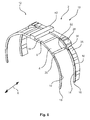
- Fig. 1 to 3 show a cabin structural segment 2 comprising an arch segment 4 and a cover segment 6, the representation of the cabin structural segment 2 in the individual figures differing merely in terms of the views.
- the arch segment 4 and the cover segment 6 are rigidly interconnected.
- Fig. 1 also shows a centre plane 8 which extends parallel to an aircraft longitudinal direction X which is represented by a double arrow.
- the centre plane 8 divides the cabin structural segment 2 into a first cabin structural subsegment 10 and a second cabin structural subsegment 12.
- the first cabin structural subsegment 10 is mirror-symmetrical to the second cabin structural subsegment 12.
- the first cabin structural subsegment 10 and the second cabin structural subsegment 12 are each formed in one piece.
- the representation selected in this case shows both a cabin structural segment 2 formed in one piece and a cabin structural segment 2 made up of the first cabin structural subsegment 10 and the second cabin structural subsegment 12.
- Each cabin structural subsegment 10, 12 and the cabin structural segment 2 formed in one piece are each designed to be self-supporting.
- the arch segment 4 extends substantially along a fuselage structure (not shown in this case) of an aircraft.
- the cover segment 6 is formed substantially parallel to a floor structure (also not shown in this case) of an aircraft.
- the cabin structural segment 2 has, in the region of the arch segments 4 thereof, a respective opening 14, the two openings 14 opposing one another.
- the individual elements are described below merely in connection with the first cabin structural subsegment 10, since this is more visible.
- the representation selected in this case also applies for the second cabin structural subsegment 12 and for the cabin structural segment 2 formed in one piece.
- the opening 14, which is shown in the first cabin structural subsegment 10 and basically corresponds to an opening (not shown in this case) for a door in a fuselage structure, is defined by two frame longitudinal profiles 16 and a frame part 22 in the form of a frame transverse profile.
- the two frame longitudinal profiles 16 and the frame transverse profile 22 are components of the arch segment 4 and are accordingly formed in one piece with the first cabin structural subsegment 10.
- Each frame longitudinal profile 16 extends from a first end 18 of the frame longitudinal profile to a second end 20 of the frame longitudinal profile.
- the first end 18 of each frame longitudinal profile can be rigidly connected to a floor structure (not shown in this case).
- the second end 20 of each frame longitudinal profile ends at the frame transverse profile 22 and is rigidly connected thereto.
- the frame transverse profile 22 extends in a screen-shaped manner and substantially parallel to the floor structure in the direction of the fuselage structure.
- the cabin structural segment 2 also has, at its sides which extend transverse to the aircraft longitudinal direction X, a peripheral edge 23.
- the cabin structural segment 2 thus forms a U-shaped cross-section when looking towards the centre plane 8.
- the peripheral edge 23 can also coincide with one frame longitudinal profile 16 or the two frame longitudinal profiles 16.
- the frame longitudinal profile 16 is spaced apart from the peripheral edge 23.
- widths B are therefore sufficient for self-supporting styling.
- the two frame longitudinal profiles 16 do not comprise a connecting element, for example in the form of a sill, connecting the two frame longitudinal profiles 16 in the vicinity of the floor structure and thus in the region of the first ends 18 of the two frame longitudinal profiles.
- a sill-less passage through the opening 14 of the cabin structural segment 2 is thus possible for passengers.
- Fig. 4 is a 3D side view of a cabin structural arrangement 25 comprising the cabin structural segment 2 already known from Fig. 1 to 3 and a cabin structural unit 24.
- the cabin structural unit 24 is rigidly connected to the cabin structural segment 2 in the aircraft longitudinal direction X.
- the cabin structural segment 2 can be made in one piece or assembled from the first 10 and the second cabin structural subsegment 12.
- On each side along the aircraft longitudinal direction X the cabin structural unit 24 has an indentation 26 for receiving cabin built-in elements in the form of overhead storage compartments (not visible in this case).
- the cabin structural unit 24 is also formed so as to be self-supporting. In this case, ends 30 of the cabin structural unit 24 are fastened only to the floor structure (not shown in this case).
- the elements which can be used to support the cabin structural unit 24 on the fuselage structure in a moment-free manner are not shown on an outer face 32, facing the fuselage structure, of the cabin structural unit 24.
- an outer face 34, facing the fuselage structure, of the cabin structural segment 2 has no elements which could be used to connect the cabin structural segment 2 to the fuselage structure.
- the outer face 34 also has no elements which could be used to support the cabin structural segment 2 on the fuselage structure.
- the cabin structural unit 24 also has openings 28 for windows of the aircraft.
- Fig. 5 shows the first cabin structural subsegment 10.
- the cabin structural segment 2 has been divided mechanically along the centre plane 8 in the aircraft longitudinal direction X into the first 10 and the second cabin structural subsegment 12, only the first cabin structural subsegment 10 being shown in this case. Otherwise, the configuration of the cabin structural subsegment 10 is no different from the representation of Fig. 1 to 3 .
- Fig. 6 is a 3D side view of the cabin structural segment 2 comprising a transition segment 36 and an electric unit 40 which is rigidly connected to the outer face 34 of the cabin structural segment 2.
- the electric unit 40 for distributing power into a passenger cabin extends along the aircraft longitudinal direction X.
- the electric unit 40 can also be arranged transverse to the aircraft longitudinal direction X.
- the transition segment 36 is rigidly fastened to the cabin structural segment 2.
- the transition segment 36 can also be formed in one piece with the cabin structural segment 2.
- the transition segment 36 has indentations 26 in which storage compartments of the cabin structural unit 24 can be arranged.
- the electric unit 40 is connected only to the cover segment 6 of the cabin structural segment 2 and has no fastening to the adjacent fuselage structure.
- the electric unit 40 also does not hinder the self-supporting structure of the cabin structural segment 2 in such a way that connections to the fuselage structure would then be necessary.
- Fig. 7 shows the cabin structural arrangement 25 comprising the cabin structural segment 2 comprising the transition segment 36 from Fig. 6 and the cabin structural unit 24 already known from Fig. 4 .
- a damping element 42 is arranged at an interface 41 between the transition segment 36 and the cabin structural unit 24.
- the transition segment 36 is also formed in accordance with the cabin structural unit 24, in such a way that an inner face 43, facing the passenger cabin, of the cabin structural unit 24 and an inner face 45, likewise facing the passenger cabin, of the transition segment 36 produce an aesthetic overall impression.
- the inner face 43 of the cabin structural unit 24 transitions smoothly into the inner face 45 of the transition segment 36.
- Fig. 8 is a plan view of the cabin structural arrangement 25 from Fig. 7 . It can clearly be seen how small the width B of the frame longitudinal profile 16 and of the peripheral edge 23 is, in the selected embodiment the edge 23 transitioning into the frame longitudinal profile 16 and continuously having the width B. The width is selected from 2 to 5 mm.
- Fig. 9 is a 3D representation of a cross-section through an aircraft fuselage 44.
- the fuselage structure 46 and the floor structure 48 are clearly visible.
- the fuselage structure 46 basically consists of formers 50, stringers (not shown in this case) and an outer skin 52.
- the fuselage structure 46 also has two mutually opposing openings 54 which can be sealed by means of doors (not shown in this case) which open into an environment 58.
- the opening 54 is defined by longitudinal sides 62 of the opening, which oppose one another and extend substantially transverse to the floor structure 48, and an upper side opposite the floor structure 48.
- the fuselage structure 46 defines an interior 56 and separates it from the environment 58.
- a passenger wishing to enter the aircraft passes from the environment 58 into the interior 56 through the opening 54, for example via a gangway.
- the interior 56 can thus be connected to the environment 58 via the sealable opening 54.
- the floor structure 48 mainly consists of crossbars 51 which extend transverse to the aircraft longitudinal direction X and are supported on the formers by means of tension-compression rods 53.
- a portion of the interior 56 is equipped with cabin structural units 24, the inner faces 43 of which define the passenger cabin. It can clearly be seen that the ends 30 of the cabin structural unit 24 are connected to the floor structure 48.
- Overhead storage compartments 60 are already mounted on the cabin structural units 24.
- the cabin structural segment 2 is divided into the first 10 and the second cabin structural subsegment 12, only the first cabin structural subsegment 10 already known from Fig. 5 being shown in this case.
- the first cabin structural subsegment 10 has been displaced from the environment 58 into the interior 56 through the opening 54 of the fuselage structure 46. It can clearly be seen that the first cabin structural subsegment 10 is wider than the opening 54, and the first cabin structural subsegment 10 was therefore guided on end through the opening 54.
- Fig. 10 differs from the representation of Fig. 9 in that the first cabin structural subsegment 10 has been displaced from its upended position in such a way that the first ends 18 of the frame longitudinal profiles and thus the first cabin structural subsegment 10 were then positioned at a predetermined location in the interior 56, or rather on the floor structure 48.
- Fig. 11 differs from the representation of Fig. 10 in that the first cabin structural subsegment 10 has been displaced into its final position.
- the second cabin structural subsegment 12 is not shown.
- the second cabin structural subsegment would also be fastened to the floor structure and, together with the first cabin structural subsegment 10, would form the self-supporting cabin structural segment 2.
- the two cabin structural subsegments 10, 12 are also each formed so as to be individually self-supporting. It can clearly be seen that the first cabin structural subsegment 10 and thus also the cabin structural segment 2 frame the opening 54 of the fuselage structure 46.
- the two frame longitudinal profiles 16 frame the longitudinal sides 62 of the opening and the frame transverse profile 22 frames the upper side 64 of the opening 54.
- the two frame longitudinal profiles 16 and the frame transverse profile 22 are formed in such a way that a gap S between the cabin structural segment 2 and the fuselage structure 46, which gap extends around the two frame longitudinal profiles 16 and the frame transverse profile 22, is minimal.
- a situation can be avoided in which, during flight operation, heat from the subsequent passenger cabin would be drawn out to the cold fuselage structure 46 via a gap which might otherwise be present in a wider form between the frame transverse profile 22 of the cabin structural segment 2 and a closed lined door. This would result in a draught in the region of the openings 54, and this could impact on the comfort of passengers sitting in the vicinity of the opening 54.
- the configuration of the cabin boarding module as a self-supporting cabin structural segment 2 makes it possible to omit cold bridges and structure-borne-noise bridges owing to the lack of connecting elements between the cabin structural segment 2 and the fuselage structure 46.
- Equipment holders and structural holders are also omitted.
- the number of individual parts is also reduced, and this in turn results in a reduction in tools and a reduction in reference documentation and the management thereof.
- the assembly is also greatly simplified.
- electric components such as high channels, cabling or other electric, pneumatic or hydraulic devices can be arranged directly at the cabin structural segment 2. Interfaces are also reduced, in that the plurality of lining panels required to construct the boarding module has been reduced to a single cabin structural segment 2. This also results in significant savings in terms of production and assembly costs.
Landscapes
- Engineering & Computer Science (AREA)
- Mechanical Engineering (AREA)
- Aviation & Aerospace Engineering (AREA)
- Body Structure For Vehicles (AREA)
Abstract
The invention relates to a cabin structural segment (2) for an aircraft comprising a fuselage structure (46) and a floor structure (48), the fuselage structure (46) defining an interior (56) and separating it from an environment (58). The fuselage structure (46) comprises an opening (54) for a door. It is possible to provide via the opening (54) a connection between the interior (56) and the environment (58). The cabin structural segment (2) is designed to be self-supporting. The cabin structural segment (2) is fastenable exclusively to the floor structure (48). The cabin structural segment (2) is constructed in such a way that the one cabin structural segment (2) frames the opening (54).
Description
- This application claims the benefit of the filing date of German Patent Application No.
10 2011 102 364.3 filed May 24, 2011 and of United States Provisional Patent Application No.61/489,612 filed May 24, 2011 - The present invention relates to a cabin structural segment for an aircraft. In particular, the present invention relates to a cabin structural segment for an aircraft, which segment is designed to be self-supporting and frames an opening, an aircraft comprising the cabin structural segment, a cabin structural arrangement comprising the cabin structural segment and a cabin structural unit, an aircraft comprising the cabin structural arrangement, and a method for installing the cabin structural segment for an aircraft.
- In modem commercial aircraft, cabin built-in elements, for example luggage compartments, lining parts or other interior built-in elements, are fastened directly to an aircraft structure, for example the formers, the stringers or other load-bearing elements of the aircraft fuselage. Owing to a wide range of structural stresses, for example the build-up of a pressure field in the passenger cabin, thermal deformations or flight mechanical loads, the aircraft structure is constantly subject to deformations. These deformations of the aircraft structure inevitably also result in a change in the position of the cabin built-in elements, since these are fastened directly to the structure.
- In order to counteract these deformations of the aircraft structures and thus the displacements of the cabin built-in elements, in particular the lining parts, longitudinal and radial gaps having a sufficient width, which may for example be between 8 mm and approximately 25 mm, extend between the cabin built-in elements.
- The door frames and the covers of the boarding regions in particular are fastened from many individual components to fastening elements which are screwed or riveted directly or indirectly to the structure. Production inaccuracies of the individual components and addition of individual tolerances when assembling the individual components make it difficult to attach the door frames and the cover components precisely. For aesthetic reasons, the individual components which face the passenger cabin and can be seen by the passengers must be aligned with one another, since disharmony in the transition from one visible individual component to the adjacent, likewise visible individual component stands out and inevitably results in complaints. The entire door frame and cover assembly in the boarding region is therefore a very complex process and thus a very demanding assembly operation, which is therefore correspondingly time-consuming and thus cost-intensive.
-
DE 10 2006 048 376 discloses a self-supporting cabin structural unit for an aircraft, which unit can be fastened only to a floor structure and can be supported in a moment-free manner on a fuselage structure, the cabin structural unit being designed for attaching cabin built-in elements such as luggage compartments, seat units or step elements. - It can be considered an object of the invention to provide a cabin structure for the door frames and the covers of the boarding regions for a commercial aircraft, in which structure the number of individual components is reduced and the orientation of the individual components is simplified.
- The object is achieved by the subject-matters of the independent claims. Other advantageous configurations emerge from the subject-matters of the dependent claims.
- According to a first embodiment of the invention, a cabin structural segment for an aircraft comprising a fuselage structure and a floor structure is provided. The fuselage structure defines an interior and separates the interior from an environment. The fuselage structure comprises an opening for a door, it being possible to provide via the opening a connection between the interior and the environment. The cabin structural segment is designed to be self-supporting. The cabin structural segment can be fastened exclusively to the floor structure. The cabin structural segment is formed in such a way that the one cabin structural segment frames the opening.
- In this context, fuselage structure is to be understood to mean reinforcing elements of the aircraft fuselage, for example stringers, formers or the outer skin. The floor structure generally consists of crossbars to which, for example, the rows of seats are fastened in modem commercial aircraft. For their part, the crossbars are usually supported on the formers of the fuselage structure by means of tension-compression rods, known as tie rods. The opening in the fuselage structure is to be understood to mean the opening through which, for example, passengers coming from the gangway enter the aircraft, or rather the interior. This opening can be sealed by means of an aircraft door. Self-supporting is to be understood to mean that the cabin structural segment does not require further external load-bearing elements in order to fulfil its function. The construction thus supports itself. Thus, all the loads which occur during operation are absorbed centrally in the cabin structural segment. In this case, all the forces and/or moments acting on the cabin structural segment are introduced exclusively into the floor structure. In addition, between the cabin structural segment and the fuselage structure there are no fastening elements which would be used to fasten the cabin structural elements to the fuselage structure. An intermediate space located between the fuselage structure and the cabin structural segment is thus free from fastening means. Owing to the lack of fastening elements of this type between the fuselage structure and the cabin structural segment, forces acting on the fuselage structure, as are produced for example by wind, temperature, pressure differences or other structural movements, are also not transmitted to the cabin structural segment. The cabin structural segment thus forms a unitary, self-supporting static unit, without absorbing deformation forces and/or deformation moments of the fuselage structure.
- The framing formed in the cabin structural segment may be smaller than, the same size as, or larger than the opening for the door in the fuselage structure, which door is to be opened outwards, that is to say into the environment. Of course, the framing can also be selected in such a way that the door could be opened into the interior. The size of the area framed by the framing may thus not be bound to the size of the opening for the door. Owing to aesthetic and technical considerations, the size of the area framed by the framing will in general basically correspond to the size of the opening in the fuselage structure. Against the background of the aesthetics in particular, an inner lining of the door comprising the cabin structural segment can be formed in such a way that a harmonious overall impression is produced. Owing to the lack of fastening elements between the fuselage structure and the cabin structural segment, cold bridges and structure-borne-noise bridges can be omitted. Equipment holders and structural holders, using which individual panels were previously fastened to the fuselage structure, are also omitted. Individual parts can thus be reduced significantly. Owing to the avoidance of fastening elements and individual panels for constructing the door frames and the covers of the boarding regions, tools for producing the individual parts can be reduced. Owing to the styling of an individual self-supporting cabin structural segment which can be fastened exclusively to the floor structure and when installed frames the opening in the fuselage structure, the assembly is simplified. In addition, reference documentation and management thereof can be reduced. Electric components such as lighting, high channels, cabling or supply units can also be fastened directly to the cabin structural segment. Interfaces, as were previously required between the individual panels, can also be omitted. Interfaces are thus reduced. Overall, the provision of a cabin structural segment of this type results in a significant saving in terms of production and assembly costs.
- In visual terms, the cabin structural segment can be formed as a free-standing arch which is formed in one piece and through which a passenger can enter the interior of the aircraft.
- According to a further embodiment of the invention, the one cabin structural segment frames two mutually opposing doors.
- Specifically owing to styling of this type, a separate cabin structural segment is not required for every door. Rather, two mutually opposing openings can be framed in a single cabin structural segment.
- According to a further embodiment of the invention, the one cabin structural segment frames only mutually opposing longitudinal sides of an opening, which extend substantially transverse to the floor structure, and an upper side, opposing the floor structure, of the opening.
- The opening is thus framed by the one cabin structural segment on three sides, namely at the upper side opposing the floor structure and at the two longitudinal sides of the opening of the cabin structural segment, but not at the side facing the floor structure. Passage through a frame, framing the opening, of the cabin structural segment thus takes place in a sill-free manner. The term sill-free is thus to be understood to mean that the cabin structural segment does not require a frame element which reinforces the cabin structural segment in the region of the floor structure.
- According to a further embodiment of the invention, the cabin structural segment comprises a frame part which frames the upper side, the frame part extending in a screen-like manner towards the fuselage structure.
- The frame part need not necessarily be straight; it can also be curved, for example. In this case, the frame part can be formed in such a way that it extends as close as possible to the opening for the door in the fuselage structure. This can be achieved for example by guiding the upper side of the frame part which frames the opening as close as possible to the fuselage structure in a screen-like manner. This screen can for example be formed parallel to the floor structure. A configuration of this type avoids the possibility that, during flight operation, heat from the passenger cabin could be drawn out towards the cold fuselage structure via a gap which might otherwise be present between the framing of the cabin structural segment and the opening in the fuselage structure, despite the door being closed. This could result in an airstream from the passenger cabin towards the opening, or rather the door. Of course, for improved thermal insulation, the cabin structural segment can comprise a sealing element which can be connected to the fuselage structure. However, this insulating element may be designed in such a way that it cannot transmit any forces between the fuselage structure and the cabin structural segment. The insulating element can also be constructed in a noise-reducing and heat-insulating manner. Of course, frame parts which frame the longitudinal sides of the opening can also be brought as close as possible to the opening.
- According to a further embodiment of the invention, the cabin structural segment comprises an arch segment and a cover segment, the arch segment extending substantially along an inner face of the fuselage structure from the floor structure to the cover segment. The cover segment is spaced apart from the floor structure. The arch segment and the cover segment are rigidly interconnected.
- Of course, the cover segment can be formed in such a way that it also extends substantially along an inner face of the fuselage structure. However, this cover segment can also be planar, in such a way that it extends substantially parallel to the floor structure. In a configuration of this type in particular, a space is produced between the cabin structural segment, or rather the cover segment, and the fuselage structure, in which space aircraft components can be accommodated such that they are not visible to passengers. The cover segment and the arch segment can be formed in one piece. The cover segment can be spaced so far apart from the floor structure that there is sufficient spacing between a standing passenger and this cover segment.
- According to a further embodiment of the invention, the cover segment comprises an outer face, the outer face being adjacent to the fuselage structure. An electric unit for supplying a passenger cabin with power can be fastened to the outer face.
- In this case, the electric unit for the power supply can be mounted in the interior either before or after the assembly of the cabin structural segment. The electric unit is formed in such a way that, if the electric unit is mounted on the outer face of the cover segment and is thus not visible to passengers, the electric unit is not additionally fastened to the fuselage structure.
- According to a further embodiment of the invention, the cabin structural segment can be divided substantially centrally in the aircraft longitudinal direction, such that a first cabin structural segment and a second cabin structural segment are formed.
- A configuration of this type makes it possible on one hand for the cabin structural segment to be produced more easily and also handled more easily by the producer. On the other hand, a division of the cabin structural segment makes it possible for the cabin structural segment produced in cabin structural subsegments to be inserted into a fully assembled fuselage structure through the opening in the fuselage structure to the interior, positioned on the floor structure and orientated relative to the opening in the fuselage structure more easily than a cabin structural segment produced in one piece. After positioning and orientation, the two cabin structural subsegments can be interconnected. In this case, too, the cabin structural segment made up of the first and the second cabin structural subsegment does not comprise any fastening elements with regard to the fuselage structure; rather, it is fastened only to the floor structure. The division can also offer the advantage that less space is required to put up the cabin structural subsegments within the fuselage structure than would be the case for a cabin structural segment produced in one piece.
- According to a further embodiment of the invention, the first and the second cabin structural segment are formed so as to be identical.
- This can result in a saving with regard to the production and tool costs. Styling of this type also reduces the variety of the individual parts.
- According to a further embodiment of the invention, the cabin structural segment comprises at least one transition segment in the aircraft longitudinal direction, the transition segment being rigidly connected to the cabin structural segment.
- In particular, the transition segment, which extends towards the lining parts of the passenger cabin, can be formed in such a way that an inner face, facing the passenger cabin, of the transition segment follows an inner contour formed by the lining parts. Thus, a passenger will not perceive the cabin structural segment as a separate component within the overall styling of the passenger cabin. It is also possible to construct the passenger cabin in the region of the windows using individual panels according to the prior art and only construct the boarding region comprising the self-supporting cabin structural segment using the transition segment. Of course, the transition segment can also accommodate seats, doors for toilet facilities or storage compartments.
- According to a further embodiment of the invention, an aircraft comprising a cabin structural segment of this type is provided.
- According to a further embodiment of the invention, a cabin structural arrangement for an aircraft comprising a fuselage structure and a floor structure is provided, it being possible to connect the cabin structural segment in the aircraft longitudinal direction to a cabin structural unit for attaching cabin built-in elements for an aircraft. The cabin structural unit is arranged in such a way that a cabin built-in element can be attached. The cabin structural unit is formed so as to be self-supporting. The cabin structural unit can be fastened only to the floor structure. The cabin structural unit can be supported on the fuselage structure in a moment-free manner.
- The cabin structural segment can thus be connected to a cabin structural unit as described in
DE 10 2006 048 376 - According to a further embodiment of the invention, an aircraft comprising a cabin structural arrangement of this type is provided.
- According to a further embodiment of the invention, a method for installing a cabin structural segment for an aircraft comprising a fuselage structure and a floor structure is provided, the fuselage structure defining an interior and separating it from an environment. The fuselage structure comprises an opening for a door, it being possible to provide via the opening a connection between the interior and the environment. The method comprises the following steps: pre-assembling the cabin structural segment in the environment of the fuselage structure, guiding the pre-assembled cabin structural segment through the opening of the fuselage structure into the interior, positioning the pre-assembled cabin structural segment at a predetermined location in the interior in such a way that the at least one opening is framed by the cabin structural segment, and fastening the cabin structural segment exclusively to the floor structure, the cabin structural segment being formed so as to be self-supporting.
- The method steps may relate mainly to the installation of a cabin structural segment produced in one piece.
- According to a further embodiment of the invention, a method for installing a cabin structural segment for an aircraft comprising a fuselage structure and a floor structure is provided, the fuselage structure defining an interior and separating it from an environment. The fuselage structure comprises an opening for a door, it being possible to provide via the opening a connection between the interior and the environment. The method comprises the following steps: pre-assembling the cabin structural segment in the environment of the fuselage structure, dividing the pre-assembled cabin structural segment into a first and a second cabin structural subsegment in the environment, guiding the first and the second cabin structural subsegment through the opening of the fuselage structure into the interior, positioning the first and the second cabin structural subsegment at a predetermined location in the interior in such a way that the at least one opening is framed by the first and/or the second cabin structural subsegment, assembling the first and the second cabin structural subsegment to form the cabin structural segment, and fastening the cabin structural segment exclusively to the floor structure, the cabin structural segment being formed so as to be self-supporting.
- It is noted that ideas regarding the invention are described herein in connection with a cabin structural segment, an aircraft comprising a cabin structural segment, a cabin structural arrangement, an aircraft comprising a cabin structural arrangement, and a method for installing a cabin structural segment. In this context, it is clear to a person skilled in the art that the individual features described can be combined with one another in a variety of ways in order thus also to arrive at other configurations of the invention.
- Embodiments of the invention are described below with reference to the appended figures. The figures are merely schematic and are not to scale.
- Fig. 1
- is a 3D side view of a cabin structural segment;
- Fig. 2
- is a further 3D side view of the cabin structural segment from
Fig. 1 ; - Fig. 3
- is a 3D plan view of the cabin structural segment from
Fig. 1 ; - Fig. 4
- is a 3D side view of a cabin structural arrangement comprising the cabin structural segment from
Fig. 1 and a cabin structural unit; - Fig. 5
- is a 3D side view of a first cabin structural subsegment;
- Fig. 6
- is a 3D side view of a cabin structural segment comprising a transition segment and an electric unit rigidly connected to the cabin structural segment;
- Fig. 7
- shows a cabin structural arrangement comprising the cabin structural segment from
Fig. 6 and a cabin structural unit; - Fig. 8
- is a plan view of the cabin structural arrangement from
Fig. 7 ; - Fig. 9
- is a 3D representation of a cross-section through a fuselage structure of an aircraft, in which fuselage structure a first cabin structural subsegment has been inserted into an interior through an opening for a door;
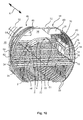
- Fig. 10
- is a further 3D representation of a cross-section through a fuselage structure of an aircraft, the first cabin structural subsegment from
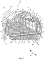
Fig. 9 having been positioned at a predetermined location on a floor structure; and - Fig. 11
- is a further 3D representation of a cross-section through a fuselage structure of an aircraft, the first or the second cabin structural subsegment from
Fig. 10 framing the opening for a door. -
Fig. 1 to 3 show a cabinstructural segment 2 comprising anarch segment 4 and acover segment 6, the representation of the cabinstructural segment 2 in the individual figures differing merely in terms of the views. In this case, thearch segment 4 and thecover segment 6 are rigidly interconnected.Fig. 1 also shows acentre plane 8 which extends parallel to an aircraft longitudinal direction X which is represented by a double arrow. In this case, thecentre plane 8 divides the cabinstructural segment 2 into a first cabinstructural subsegment 10 and a second cabinstructural subsegment 12. The first cabinstructural subsegment 10 is mirror-symmetrical to the second cabinstructural subsegment 12. In the representation selected in this case, the first cabinstructural subsegment 10 and the second cabinstructural subsegment 12 are each formed in one piece. The representation selected in this case shows both a cabinstructural segment 2 formed in one piece and a cabinstructural segment 2 made up of the first cabinstructural subsegment 10 and the second cabinstructural subsegment 12. Each cabinstructural subsegment structural segment 2 formed in one piece are each designed to be self-supporting. Thearch segment 4 extends substantially along a fuselage structure (not shown in this case) of an aircraft. Thecover segment 6 is formed substantially parallel to a floor structure (also not shown in this case) of an aircraft. The cabinstructural segment 2 has, in the region of thearch segments 4 thereof, arespective opening 14, the twoopenings 14 opposing one another. The individual elements are described below merely in connection with the first cabinstructural subsegment 10, since this is more visible. Obviously, the representation selected in this case also applies for the second cabinstructural subsegment 12 and for the cabinstructural segment 2 formed in one piece. Theopening 14, which is shown in the first cabinstructural subsegment 10 and basically corresponds to an opening (not shown in this case) for a door in a fuselage structure, is defined by two framelongitudinal profiles 16 and aframe part 22 in the form of a frame transverse profile. The two framelongitudinal profiles 16 and the frametransverse profile 22 are components of thearch segment 4 and are accordingly formed in one piece with the first cabinstructural subsegment 10. Each framelongitudinal profile 16 extends from afirst end 18 of the frame longitudinal profile to asecond end 20 of the frame longitudinal profile. Thefirst end 18 of each frame longitudinal profile can be rigidly connected to a floor structure (not shown in this case). Thesecond end 20 of each frame longitudinal profile ends at the frametransverse profile 22 and is rigidly connected thereto. The frametransverse profile 22 extends in a screen-shaped manner and substantially parallel to the floor structure in the direction of the fuselage structure. The cabinstructural segment 2 also has, at its sides which extend transverse to the aircraft longitudinal direction X, aperipheral edge 23. The cabinstructural segment 2 thus forms a U-shaped cross-section when looking towards thecentre plane 8. Theperipheral edge 23 can also coincide with one framelongitudinal profile 16 or the two framelongitudinal profiles 16. In the embodiment shown in this case, the framelongitudinal profile 16 is spaced apart from theperipheral edge 23. In particular when using CFRP materials, very stabile and very light constructions are possible, and widths B of a few millimetres between an outer face, facing theopening 14, of the framelongitudinal profile 16 and an outer face, opposite the outer face of the frame longitudinal profile, of the adjacentperipheral edge 23 are therefore sufficient for self-supporting styling. It can also clearly be seen that the two framelongitudinal profiles 16 do not comprise a connecting element, for example in the form of a sill, connecting the two framelongitudinal profiles 16 in the vicinity of the floor structure and thus in the region of the first ends 18 of the two frame longitudinal profiles. A sill-less passage through theopening 14 of the cabinstructural segment 2 is thus possible for passengers. -
Fig. 4 is a 3D side view of a cabinstructural arrangement 25 comprising the cabinstructural segment 2 already known fromFig. 1 to 3 and a cabinstructural unit 24. In this case, the cabinstructural unit 24 is rigidly connected to the cabinstructural segment 2 in the aircraft longitudinal direction X. The cabinstructural segment 2 can be made in one piece or assembled from the first 10 and the second cabinstructural subsegment 12. On each side along the aircraft longitudinal direction X the cabinstructural unit 24 has anindentation 26 for receiving cabin built-in elements in the form of overhead storage compartments (not visible in this case). The cabinstructural unit 24 is also formed so as to be self-supporting. In this case, ends 30 of the cabinstructural unit 24 are fastened only to the floor structure (not shown in this case). The elements which can be used to support the cabinstructural unit 24 on the fuselage structure in a moment-free manner are not shown on anouter face 32, facing the fuselage structure, of the cabinstructural unit 24. In contrast thereto, anouter face 34, facing the fuselage structure, of the cabinstructural segment 2 has no elements which could be used to connect the cabinstructural segment 2 to the fuselage structure. Theouter face 34 also has no elements which could be used to support the cabinstructural segment 2 on the fuselage structure. The cabinstructural unit 24 also hasopenings 28 for windows of the aircraft. -
Fig. 5 shows the first cabinstructural subsegment 10. In contrast to the representations ofFig. 1 to 3 , in this case the cabinstructural segment 2 has been divided mechanically along thecentre plane 8 in the aircraft longitudinal direction X into the first 10 and the second cabinstructural subsegment 12, only the first cabinstructural subsegment 10 being shown in this case. Otherwise, the configuration of the cabinstructural subsegment 10 is no different from the representation ofFig. 1 to 3 . -
Fig. 6 is a 3D side view of the cabinstructural segment 2 comprising atransition segment 36 and anelectric unit 40 which is rigidly connected to theouter face 34 of the cabinstructural segment 2. In this case, theelectric unit 40 for distributing power into a passenger cabin extends along the aircraft longitudinal direction X. Of course, theelectric unit 40 can also be arranged transverse to the aircraft longitudinal direction X. Thetransition segment 36 is rigidly fastened to the cabinstructural segment 2. Thetransition segment 36 can also be formed in one piece with the cabinstructural segment 2. Thetransition segment 36 hasindentations 26 in which storage compartments of the cabinstructural unit 24 can be arranged. Theelectric unit 40 is connected only to thecover segment 6 of the cabinstructural segment 2 and has no fastening to the adjacent fuselage structure. Theelectric unit 40 also does not hinder the self-supporting structure of the cabinstructural segment 2 in such a way that connections to the fuselage structure would then be necessary. -
Fig. 7 shows the cabinstructural arrangement 25 comprising the cabinstructural segment 2 comprising thetransition segment 36 fromFig. 6 and the cabinstructural unit 24 already known fromFig. 4 . A dampingelement 42 is arranged at an interface 41 between thetransition segment 36 and the cabinstructural unit 24. At the interface 41 thetransition segment 36 is also formed in accordance with the cabinstructural unit 24, in such a way that aninner face 43, facing the passenger cabin, of the cabinstructural unit 24 and aninner face 45, likewise facing the passenger cabin, of thetransition segment 36 produce an aesthetic overall impression. In the embodiment shown in this case, theinner face 43 of the cabinstructural unit 24 transitions smoothly into theinner face 45 of thetransition segment 36. -
Fig. 8 is a plan view of the cabinstructural arrangement 25 fromFig. 7 . It can clearly be seen how small the width B of the framelongitudinal profile 16 and of theperipheral edge 23 is, in the selected embodiment theedge 23 transitioning into the framelongitudinal profile 16 and continuously having the width B. The width is selected from 2 to 5 mm. -
Fig. 9 is a 3D representation of a cross-section through anaircraft fuselage 44. Thefuselage structure 46 and thefloor structure 48 are clearly visible. Thefuselage structure 46 basically consists offormers 50, stringers (not shown in this case) and anouter skin 52. Thefuselage structure 46 also has two mutually opposingopenings 54 which can be sealed by means of doors (not shown in this case) which open into anenvironment 58. Theopening 54 is defined bylongitudinal sides 62 of the opening, which oppose one another and extend substantially transverse to thefloor structure 48, and an upper side opposite thefloor structure 48. Thefuselage structure 46 defines an interior 56 and separates it from theenvironment 58. A passenger wishing to enter the aircraft passes from theenvironment 58 into the interior 56 through theopening 54, for example via a gangway. The interior 56 can thus be connected to theenvironment 58 via thesealable opening 54. Thefloor structure 48 mainly consists ofcrossbars 51 which extend transverse to the aircraft longitudinal direction X and are supported on the formers by means of tension-compression rods 53. A portion of the interior 56 is equipped with cabinstructural units 24, the inner faces 43 of which define the passenger cabin. It can clearly be seen that the ends 30 of the cabinstructural unit 24 are connected to thefloor structure 48. Overhead storage compartments 60 are already mounted on the cabinstructural units 24. To facilitate handling, the cabinstructural segment 2 is divided into the first 10 and the second cabinstructural subsegment 12, only the first cabinstructural subsegment 10 already known fromFig. 5 being shown in this case. The first cabinstructural subsegment 10 has been displaced from theenvironment 58 into the interior 56 through theopening 54 of thefuselage structure 46. It can clearly be seen that the first cabinstructural subsegment 10 is wider than theopening 54, and the first cabinstructural subsegment 10 was therefore guided on end through theopening 54. -
Fig. 10 differs from the representation ofFig. 9 in that the first cabinstructural subsegment 10 has been displaced from its upended position in such a way that the first ends 18 of the frame longitudinal profiles and thus the first cabinstructural subsegment 10 were then positioned at a predetermined location in the interior 56, or rather on thefloor structure 48. -
Fig. 11 differs from the representation ofFig. 10 in that the first cabinstructural subsegment 10 has been displaced into its final position. For the sake of clarity, the second cabinstructural subsegment 12 is not shown. The second cabin structural subsegment would also be fastened to the floor structure and, together with the first cabinstructural subsegment 10, would form the self-supporting cabinstructural segment 2. It is self-evident that the two cabinstructural subsegments structural subsegment 10 and thus also the cabinstructural segment 2 frame theopening 54 of thefuselage structure 46. In particular, the two framelongitudinal profiles 16 frame thelongitudinal sides 62 of the opening and the frametransverse profile 22 frames theupper side 64 of theopening 54. It can also be seen that the two framelongitudinal profiles 16 and the frametransverse profile 22 are formed in such a way that a gap S between the cabinstructural segment 2 and thefuselage structure 46, which gap extends around the two framelongitudinal profiles 16 and the frametransverse profile 22, is minimal. In particular owing to the styling of the very narrow gap S between thefuselage structure 46 and the frametransverse profile 22, a situation can be avoided in which, during flight operation, heat from the subsequent passenger cabin would be drawn out to thecold fuselage structure 46 via a gap which might otherwise be present in a wider form between the frametransverse profile 22 of the cabinstructural segment 2 and a closed lined door. This would result in a draught in the region of theopenings 54, and this could impact on the comfort of passengers sitting in the vicinity of theopening 54. - The configuration of the cabin boarding module as a self-supporting cabin
structural segment 2 makes it possible to omit cold bridges and structure-borne-noise bridges owing to the lack of connecting elements between the cabinstructural segment 2 and thefuselage structure 46. Equipment holders and structural holders are also omitted. The number of individual parts is also reduced, and this in turn results in a reduction in tools and a reduction in reference documentation and the management thereof. The assembly is also greatly simplified. In addition, electric components such as high channels, cabling or other electric, pneumatic or hydraulic devices can be arranged directly at the cabinstructural segment 2. Interfaces are also reduced, in that the plurality of lining panels required to construct the boarding module has been reduced to a single cabinstructural segment 2. This also results in significant savings in terms of production and assembly costs. - In addition, it should be noted that "comprising" does not exclude any other elements or steps and that "a" or "an" does not exclude a plurality. It should also be noted that features or steps which have been described with reference to one of the above embodiments can also be used in combination with other features or steps of other embodiments described above. Reference numerals in the claims are not to be considered limiting.
-
- 2
- cabin structural segment
- 4
- arch segment
- 6
- cover segment
- 8
- centre plane
- 10
- first cabin structural subsegment
- 12
- second cabin structural subsegment
- 14
- opening
- 16
- frame longitudinal profile
- 18
- first end of frame longitudinal profile
- 20
- second end of frame longitudinal profile
- 22
- frame transverse profile (frame part)
- 23
- peripheral edge
- 24
- cabin structural unit
- 25
- cabin structural arrangement
- 26
- indentation for receiving overhead storage compartments
- 28
- opening for window
- 30
- end of the cabin structural unit
- 32
- outer face of the cabin structural unit
- 34
- outer face of the cabin structural segment
- 36
- transition segment
- 40
- electric unit
- 41
- interface
- 42
- damping element
- 43
- inner face of the cabin structural unit
- 44
- aircraft fuselage
- 45
- inner face of the transition segment
- 46
- fuselage structure
- 48
- floor structure
- 50
- former
- 51
- crossbar
- 52
- outer skin
- 53
- tension-compression rod
- 54
- opening of the fuselage structure
- 56
- interior
- 58
- environment
- 60
- storage compartment
- 62
- longitudinal side of opening
- 64
- upper side
- B
- width
- S
- gap
- X
- aircraft longitudinal direction
Claims (14)
- Cabin structural segment for an aircraft comprising a fuselage structure (46) and a floor structure (48),
wherein the fuselage structure (46) defines an interior (56) and separates it from an environment (58), the fuselage structure (46) comprising an opening (54) for a door, wherein via the opening (54) a connection between the interior (56) and the environment (58) is providable;
wherein the cabin structural segment (2) is designed to be self-supporting;
wherein the cabin structural segment (2) fastenable exclusively to the floor structure (48);
wherein the cabin structural segment (2) is constructed in such a way that the opening (54) is framed by the one cabin structural segment (2). - Cabin structural segment according to claim 1,
wherein the one cabin structural segment (2) frames two mutually opposing openings (54). - Cabin structural segment according to either claim 1 or claim 2,
wherein the one cabin structural segment (2) frames only mutually opposing longitudinal sides (62) of an opening, which extend substantially transverse to the floor structure (48), and an upper side (64), opposing the floor structure (48), of the opening (54). - Cabin structural segment according to claim 3,
wherein the cabin structural segment (2) comprises a frame part (22) which frames the upper side (64), the frame part (22) extending in a screen-like manner towards the fuselage structure (46). - Cabin structural segment according to any one of the preceding claims,
wherein the cabin structural segment (2) comprises an arch segment (4) and a cover segment (6), the arch segment (4) extending substantially along an inner face of the fuselage structure (46) from the floor structure (48) to the cover segment (6), the cover segment (6) being spaced apart from the floor structure (48), the arch segment (4) and the cover segment (6) being rigidly interconnected. - Cabin structural segment according to claim 5,
wherein the cover segment (6) comprises an outer face (34), the outer face (34) being adjacent to the fuselage structure (46), it being possible for an electric unit (40) for supplying a passenger cabin with power to be fastened to the outer face (34). - Cabin structural segment according to any one of the preceding claims,
wherein the cabin structural segment (2) is dividable substantially centrally in the aircraft longitudinal direction (X), such that a first cabin structural segment (10) and a second cabin structural segment (12) are formed. - Cabin structural segment according to claim 7,
wherein the first (10) and the second cabin structural segment (12) are formed so as to be identical. - Cabin structural segment according to any one of the preceding claims,
wherein the cabin structural segment (2) comprises at least one transition segment (36) in the aircraft longitudinal direction (X), the transition segment (36) being rigidly connected to the cabin structural segment (2). - Aircraft comprising a cabin structural segment according to any one of claims 1 to 9.
- Cabin structural arrangement for an aircraft comprising a fuselage structure (46) and a floor structure (48),
wherein the cabin structural segment (2) according to any one of claims 1 to 9 is connectable to a cabin structural unit (24) for attaching cabin built-in elements (60) for an aircraft; the cabin structural unit (24) being arranged in such a way that a cabin built-in element (60) is attachable; the cabin structural unit (24) being formed so as to be self-supporting; it being possible to fasten the cabin structural unit (24) only to the floor structure (46); and it being possible to support the cabin structural unit (24) on the fuselage structure (46) in a moment-free manner. - Aircraft comprising a cabin structural arrangement according to claim 11.
- Method for installing a cabin structural segment for an aircraft comprising a fuselage structure (46) and a floor structure (48), the fuselage structure (46) defining an interior (56) and separating it from an environment (58), the fuselage structure (46) comprising an opening (54) for a door, it being possible to provide via the opening (54) a connection between the interior (56) and the environment (58);
the method comprising the following steps:pre-assembling the cabin structural segment (2) in the environment (58) of the fuselage structure (46);guiding the pre-assembled cabin structural segment (2) through the opening (54) of the fuselage structure (46) into the interior (56);positioning the pre-assembled cabin structural segment (2) at a predetermined location in the interior (56) in such a way that the at least one opening (54) is framed by the cabin structural segment (2); andfastening the cabin structural segment (2) exclusively to the floor structure (48), the cabin structural segment (2) being formed so as to be self-supporting. - Method for installing a cabin structural segment for an aircraft comprising a fuselage structure (46) and a floor structure (48), the fuselage structure (46) defining an interior (56) and separating it from an environment (58), the fuselage structure (46) comprising an opening (54) for a door, it being possible to provide via the opening (54) a connection between the interior (56) and the environment (58);
the method comprising the following steps:pre-assembling the cabin structural segment (2) in the environment (58) of the fuselage structure (46);dividing the pre-assembled cabin structural segment (2) into a first (10) and a second cabin structural subsegment (12) in the environment (48);guiding the first (10) and the second cabin structural subsegment (12) through the opening (54) of the fuselage structure (46) into the interior (56);positioning the first (10) and the second cabin structural subsegment (12) at a predetermined location in the interior (56) in such a way that the at least one opening (54) is framed by the first (10) and/or the second cabin structural subsegment (12);assembling the first (10) and the second cabin structural subsegment (12) to form the cabin structural segment (2); andfastening the cabin structural segment (2) exclusively to the floor structure (48), the cabin structural segment (2) being formed so as to be self-supporting.
Applications Claiming Priority (2)
| Application Number | Priority Date | Filing Date | Title |
|---|---|---|---|
| US201161489612P | 2011-05-24 | 2011-05-24 | |
| DE201110102364 DE102011102364A1 (en) | 2011-05-24 | 2011-05-24 | Cantilever cabin structure segment |
Publications (1)
| Publication Number | Publication Date |
|---|---|
| EP2527246A2 true EP2527246A2 (en) | 2012-11-28 |
Family
ID=46168196
Family Applications (1)
| Application Number | Title | Priority Date | Filing Date |
|---|---|---|---|
| EP20120168914 Withdrawn EP2527246A2 (en) | 2011-05-24 | 2012-05-22 | Self-supporting cabin structural segment |
Country Status (3)
| Country | Link |
|---|---|
| US (1) | US8991757B2 (en) |
| EP (1) | EP2527246A2 (en) |
| DE (1) | DE102011102364A1 (en) |
Families Citing this family (8)
| Publication number | Priority date | Publication date | Assignee | Title |
|---|---|---|---|---|
| DE102007050422B4 (en) * | 2007-10-22 | 2012-03-08 | Airbus Operations Gmbh | Aircraft component assembly system |
| EP2630037B1 (en) * | 2010-10-18 | 2020-01-22 | James M. Curry | System for overhead storage of cargo containers in upper lobe of aircraft |
| ES2404946B1 (en) * | 2011-10-21 | 2014-09-02 | Airbus Operations S.L. | AIRCRAFT FUSELAGE RESISTANT TO IMPACT AND TOLERANT TO IMPROVED DAMAGE |
| DE102012202504A1 (en) * | 2012-02-17 | 2013-08-22 | Airbus Operations Gmbh | Structural component for an aircraft or spacecraft |
| USD732459S1 (en) * | 2013-05-21 | 2015-06-23 | Airbus Corporate Jet Centre | Aircraft cabin |
| CN112193399B (en) * | 2020-11-17 | 2023-03-17 | 中航通飞华南飞机工业有限公司 | Spherical airtight end frame with large opening |
| EP4378837B1 (en) * | 2022-11-30 | 2025-06-11 | Airbus Operations GmbH | Installation system and method for installing a self-supporting framework structure |
| EP4717585A1 (en) | 2024-09-26 | 2026-04-01 | AIRBUS HELICOPTERS DEUTSCHLAND GmbH | A rotary-wing aircraft with a fuselage that comprises a load carrying shell structure and a load carrying stiffening member structure |
Citations (1)
| Publication number | Priority date | Publication date | Assignee | Title |
|---|---|---|---|---|
| DE102006048376A1 (en) | 2006-10-12 | 2008-04-17 | Airbus Deutschland Gmbh | Cabin structure unit for mounting cabin installation unit for airplane, has reinforcing rib arranged between support frames, where structure unit is designed in self-supportable manner and is mounted in airplane and floor structures |
Family Cites Families (44)
| Publication number | Priority date | Publication date | Assignee | Title |
|---|---|---|---|---|
| US2095626A (en) | 1933-04-20 | 1937-10-12 | Sperry Gyroscope Co Inc | Soundproof cabin for aircraft |
| US3142461A (en) * | 1960-05-26 | 1964-07-28 | A T S Company Ltd | Internal fittings of aircraft |
| US3416274A (en) | 1965-10-08 | 1968-12-17 | Nasa | Flexibly connected support and skin |
| US4050208A (en) | 1976-10-04 | 1977-09-27 | The Boeing Company | Aircraft interior ceiling panel assembly and attachment apparatus |
| JPS5647400A (en) | 1979-09-26 | 1981-04-30 | Kawasaki Heavy Ind Ltd | Boxxshaped cabin structure which can be mounted and demounted to and from aircraft for freight |
| JPS574455A (en) | 1980-06-06 | 1982-01-11 | Tenryu Industries | Box body with holding rail |
| US4799631A (en) | 1987-02-18 | 1989-01-24 | Atr International, Inc. | Aircraft shell module |
| US4989809A (en) | 1988-03-14 | 1991-02-05 | The Boeing Company | Removable aircraft floor structure-reinforcing strongback |
| DE59001679D1 (en) | 1989-02-06 | 1993-07-15 | Airbus Gmbh | CEILING-LUGGAGE RACK COMBINATION FOR THE AIRCRAFT PASSENGER CAB. |
| US5044578A (en) | 1989-12-27 | 1991-09-03 | White Thomas H | Universal cabin sidewall panel for aircraft |
| US5201831A (en) | 1991-11-15 | 1993-04-13 | Atr International, Inc. | Aircraft interior shell |
| GB2287517B (en) | 1994-03-14 | 1997-04-30 | Kenneth Barry Wilson | Panel assembly system |
| US5549258A (en) | 1994-12-23 | 1996-08-27 | Heath Tecna Aerospace Company | Retrofit luggage bin assembly compatible with existing aircraft bin supports |
| US5687929A (en) | 1995-06-29 | 1997-11-18 | Hexcel Corporation | Extensions for storage bins |
| DE19633469C1 (en) | 1996-08-20 | 1997-09-04 | Daimler Benz Aerospace Airbus | Device for holding overhead baggage compartments in aircraft passenger cabins |
| DE19639915A1 (en) | 1996-09-27 | 1998-06-10 | Gruenzweig & Hartmann Montage | High temperature insulation system |
| US6158690A (en) | 1998-10-30 | 2000-12-12 | Sikorsky Aircraft Corporation | Cabin interior panel system for reducing noise transmission in an aircraft |
| RU2191716C2 (en) | 1999-04-27 | 2002-10-27 | Открытое акционерное общество Таганрогский авиационный научно-технический комплекс им. Г.М.Бериева | Flying vehicle salon |
| JP4444422B2 (en) | 1999-12-15 | 2010-03-31 | 近畿車輌株式会社 | Mounting structure for inner rail partitions of railway vehicles |
| FR2829102B1 (en) | 2001-09-06 | 2004-08-06 | Eurocopter France | STRUCTURAL ASSEMBLY OF A PART OF AN AIRCRAFT AND AIRCRAFT, IN PARTICULAR A TURNING AIRCRAFT, COMPRISING SUCH A STRUCTURAL ASSEMBLY |
| US6536710B1 (en) | 2002-02-06 | 2003-03-25 | The Boeing Company | Overhead lattice support structure |
| DE10339507B4 (en) | 2003-07-18 | 2007-04-26 | Telair International Gmbh | cargo module |
| US20050044712A1 (en) | 2003-08-28 | 2005-03-03 | Gideon David E. | Sidewall panel integrated with insulation and air ducts |
| US7380752B2 (en) * | 2003-10-17 | 2008-06-03 | The Boeing Company | Aircraft interior architecture |
| US7252267B2 (en) * | 2003-10-17 | 2007-08-07 | The Boeing Company | Aircraft archway architecture |
| JP4324446B2 (en) | 2003-10-27 | 2009-09-02 | 東急車輛製造株式会社 | Vehicle outfitting structure |
| US6874731B1 (en) | 2003-11-05 | 2005-04-05 | The Boeing Company | Modular overhead stowage bin systems and associated methods |
| US6848654B1 (en) | 2004-01-09 | 2005-02-01 | The Boeing Company | Modular offset aisle overhead crew rest |
| US7270297B2 (en) | 2004-01-30 | 2007-09-18 | The Boeing Company | Hoist for aircraft cabin construction |
| FR2869289B1 (en) | 2004-04-27 | 2007-07-13 | Eads Sogerma Services Sa | INTERIOR ARRANGEMENT OF THE WINDOWS OF AN AIRCRAFT FUSELAGE. |
| US7629026B2 (en) | 2004-09-03 | 2009-12-08 | Eastman Kodak Company | Thermally controlled fluidic self-assembly |
| EP1647480B1 (en) | 2004-10-13 | 2010-12-08 | Airbus Operations GmbH | Joint covering for aircraft |
| JP3734490B2 (en) | 2004-12-06 | 2006-01-11 | 株式会社日立製作所 | Shoulder interior panel for railway vehicles |
| US7237749B2 (en) * | 2004-12-14 | 2007-07-03 | The Boeing Company | Collapsible mobile platform interior structure |
| USD539210S1 (en) * | 2005-04-28 | 2007-03-27 | The Boeing Company | Modular archway for an aircraft |
| DE102005023886A1 (en) | 2005-05-24 | 2006-12-07 | Airbus Deutschland Gmbh | Aircraft fuselage section has accessible first internal tube, accessible second internal tube and external tube whereby first internal tube and second internal tube are enclosed by external tube |
| GB0512541D0 (en) | 2005-06-20 | 2005-07-27 | James Park Associates Ltd | Aircraft interior module |
| DE102006039290A1 (en) * | 2006-08-22 | 2008-03-13 | Airbus Deutschland Gmbh | Frame element for aircraft component assembly system, has connecting struts that are provided with recesses for receiving ribs of aircraft structure when frame element is attached to aircraft structure |
| DE102006039291A1 (en) * | 2006-08-22 | 2008-03-13 | Airbus Deutschland Gmbh | Frame element for use in installation of storage bin in aircraft, has longitudinal parallel struts that extend parallel to ribs of aircraft structure, when frame element is mounted to aircraft structure |
| DE102006039292B4 (en) * | 2006-08-22 | 2010-07-22 | Airbus Deutschland Gmbh | Frame element, aircraft air conditioning system and method for mounting a frame member in an aircraft |
| US8523110B2 (en) * | 2007-03-28 | 2013-09-03 | Airbus Operations Gmbh | Door frame component of cast titanium and structural fuselage part |
| DE102007050422B4 (en) * | 2007-10-22 | 2012-03-08 | Airbus Operations Gmbh | Aircraft component assembly system |
| WO2009124832A2 (en) | 2008-04-10 | 2009-10-15 | Airbus Operations Gmbh | Aircraft having a force transmission element between a cabin structural element and a primary structure |
| DE102009024157A1 (en) | 2009-06-08 | 2011-03-03 | Airbus Operations Gmbh | System and method for manufacturing a vehicle cabin |
-
2011
- 2011-05-24 DE DE201110102364 patent/DE102011102364A1/en not_active Withdrawn
-
2012
- 2012-05-22 EP EP20120168914 patent/EP2527246A2/en not_active Withdrawn
- 2012-05-24 US US13/479,538 patent/US8991757B2/en not_active Expired - Fee Related
Patent Citations (1)
| Publication number | Priority date | Publication date | Assignee | Title |
|---|---|---|---|---|
| DE102006048376A1 (en) | 2006-10-12 | 2008-04-17 | Airbus Deutschland Gmbh | Cabin structure unit for mounting cabin installation unit for airplane, has reinforcing rib arranged between support frames, where structure unit is designed in self-supportable manner and is mounted in airplane and floor structures |
Also Published As
| Publication number | Publication date |
|---|---|
| DE102011102364A1 (en) | 2012-11-29 |
| US20120298799A1 (en) | 2012-11-29 |
| US8991757B2 (en) | 2015-03-31 |
Similar Documents
| Publication | Publication Date | Title |
|---|---|---|
| US8991757B2 (en) | Self-supporting cabin structural segment | |
| US9387920B2 (en) | Self-supporting cabin structure | |
| EP2021236B1 (en) | Aircraft fuselage structure and method for its production | |
| US8403261B2 (en) | Process for making an aircraft having a floor | |
| RU2532010C2 (en) | Frame of opening made in aircraft fuselage | |
| CN101309833B (en) | Attachment structure for securing internal equipment components of aircraft cabin | |
| EP2024227B1 (en) | Aircraft fuselage structure and method for producing it | |
| EP1353832B1 (en) | A rail vehicle carbody of modular construction | |
| EP2137064B1 (en) | Structural element for an aircraft fuselage | |
| EP3142922B1 (en) | Bulkhead assembly with pocket door for aircraft interior | |
| US8684308B2 (en) | Universal arrangement for receiving a curtain rail for a partitioning curtain | |
| US20110042516A1 (en) | Window element for a double-shell skin field of an aircraft fuselage cell | |
| EP3464012B1 (en) | Rail vehicle provided with a blast-resistant partition wall | |
| CN104185586A (en) | Cabs and railway vehicles equipped with cabs | |
| EP2700573B1 (en) | A pressurized airplane fuselage, comprising a pressure bulkhead | |
| CN101932505A (en) | safe cabin | |
| EP2813426B1 (en) | Shell structure of a fuselage at a door opening and method of forming the shell structure | |
| US11312469B2 (en) | Lintel structure for aircraft fuselage and fuselage comprising such a lintel | |
| EP3805069B1 (en) | Railway vehicle and end wall thereof | |
| EP3730284B1 (en) | Composite panel systems and methods | |
| US11167834B2 (en) | Aircraft fuselage comprising at least two transparent walls interposed between an upper portion and a lower portion of the fuselage |
Legal Events
| Date | Code | Title | Description |
|---|---|---|---|
| PUAI | Public reference made under article 153(3) epc to a published international application that has entered the european phase |
Free format text: ORIGINAL CODE: 0009012 |
|
| AK | Designated contracting states |
Kind code of ref document: A2 Designated state(s): AL AT BE BG CH CY CZ DE DK EE ES FI FR GB GR HR HU IE IS IT LI LT LU LV MC MK MT NL NO PL PT RO RS SE SI SK SM TR |
|
| AX | Request for extension of the european patent |
Extension state: BA ME |
|
| STAA | Information on the status of an ep patent application or granted ep patent |
Free format text: STATUS: THE APPLICATION HAS BEEN PUBLISHED |
|
| STAA | Information on the status of an ep patent application or granted ep patent |
Free format text: STATUS: THE APPLICATION IS DEEMED TO BE WITHDRAWN |
|
| 18D | Application deemed to be withdrawn |
Effective date: 20171201 |