EP2527210A1 - An inflator for an air bag - Google Patents
An inflator for an air bag Download PDFInfo
- Publication number
- EP2527210A1 EP2527210A1 EP20110167438 EP11167438A EP2527210A1 EP 2527210 A1 EP2527210 A1 EP 2527210A1 EP 20110167438 EP20110167438 EP 20110167438 EP 11167438 A EP11167438 A EP 11167438A EP 2527210 A1 EP2527210 A1 EP 2527210A1
- Authority
- EP
- European Patent Office
- Prior art keywords
- support
- configuration
- container
- wall
- inflator
- Prior art date
- Legal status (The legal status is an assumption and is not a legal conclusion. Google has not performed a legal analysis and makes no representation as to the accuracy of the status listed.)
- Granted
Links
Images


Classifications
-
- B—PERFORMING OPERATIONS; TRANSPORTING
- B60—VEHICLES IN GENERAL
- B60R—VEHICLES, VEHICLE FITTINGS, OR VEHICLE PARTS, NOT OTHERWISE PROVIDED FOR
- B60R21/00—Arrangements or fittings on vehicles for protecting or preventing injuries to occupants or pedestrians in case of accidents or other traffic risks
- B60R21/02—Occupant safety arrangements or fittings, e.g. crash pads
- B60R21/16—Inflatable occupant restraints or confinements designed to inflate upon impact or impending impact, e.g. air bags
- B60R21/26—Inflatable occupant restraints or confinements designed to inflate upon impact or impending impact, e.g. air bags characterised by the inflation fluid source or means to control inflation fluid flow
- B60R21/268—Inflatable occupant restraints or confinements designed to inflate upon impact or impending impact, e.g. air bags characterised by the inflation fluid source or means to control inflation fluid flow using instantaneous release of stored pressurised gas
- B60R21/274—Inflatable occupant restraints or confinements designed to inflate upon impact or impending impact, e.g. air bags characterised by the inflation fluid source or means to control inflation fluid flow using instantaneous release of stored pressurised gas characterised by means to rupture or open the fluid source
-
- Y—GENERAL TAGGING OF NEW TECHNOLOGICAL DEVELOPMENTS; GENERAL TAGGING OF CROSS-SECTIONAL TECHNOLOGIES SPANNING OVER SEVERAL SECTIONS OF THE IPC; TECHNICAL SUBJECTS COVERED BY FORMER USPC CROSS-REFERENCE ART COLLECTIONS [XRACs] AND DIGESTS
- Y10—TECHNICAL SUBJECTS COVERED BY FORMER USPC
- Y10T—TECHNICAL SUBJECTS COVERED BY FORMER US CLASSIFICATION
- Y10T137/00—Fluid handling
- Y10T137/1624—Destructible or deformable element controlled
- Y10T137/1632—Destructible element
- Y10T137/1692—Rupture disc
Definitions
- the present invention relates to an air-bag, such as an air-bag provided in a vehicle to provide protection for an occupant of the vehicle in the event of an accident.
- air-bag inflators which incorporate one or two bottles of pressure vessels containing gas under pressure.
- Each bottle is initially sealed, for instance by a metal foil.
- the foil can be initially supported by means of a support element which is held in position against the exterior side of the foil.
- the support element is moved away from the metal foil, enabling the foil to rupture under the pressure of the gas within the bottle, and enabling the gas to escape from the bottle and flow into the interior of the air-bag to inflate the air-bag.
- one bottle may contain a fuel, in the form of an oxidisable gas, and another bottle may contain an oxidising gas. When these gases escape from the gas bottles they are mixed, and may subsequently be ignited within the air-bag to complete inflation of the air-bag.
- one bottle can be used, containing suitable reactive or non-reactive gases.
- EP1778526 and US6612326 disclose arrangements of this type in which a support element is initially provided immediately behind a foil, and held in position by a flange of a piston head, or by a support that is arranged to be knocked out of position by a piston head.
- the piston is driven so that the flange or support moves away from the region behind the support element, thus allowing the support element to move away from the foil, and so allowing the pressure of gas within the bottle to rupture the foil, pushing the support element away as this occurs.
- the foil In order for systems of this type to be effective, the foil must be relatively thin, and the pressure of gas within the bottle must be relatively high. lf the foil is too thick, or the pressure of gas within the bottle is too low, there is a risk that the foil will bulge elastically and will not rupture at the required time, particularly in low-temperature conditions.
- one aspect of the present invention provides an inflator for a vehicle air-bag, the inflator comprising: a container initially containing a pressurised gas, the container having a vent opening formed in a wall thereof; a rupturable element which covers the vent opening, substantially sealing the interior of the container, the rupturable element being attached to the wall of the container at at least a first location; a first support which is attached to the wall of the container and movable with respect to the wall of the container between a first configuration, in which the first support supports a region of the rupturable element and prevents the rupturable element from rupturing, and a second configuration, the rupturable element being attached to the first support at at least a second location; a second support which, in an initial configuration, supports the first support and prevents the first support from moving from the first configuration to the second configuration, and which, in a final configuration, allows the first support to move from the first configuration to the second configuration; and an activation mechanism which, when triggered, moves the
- the first support when the first support is in the first configuration, there is a first distance between the first location and the second location; and when the first support is in the second configuration, there is a second distance between the first location and the second location, wherein the second distance is larger than the first distance.
- the portion of the rupturable element that initially extends between the first location and the second location is insufficiently elastic to stretch over the second distance, so that when the first support moves from the first configuration to the second configuration, the increase in distance between the first and second locations causes the rupturable element to rupture.
- the activation mechanism comprises a piston element which drives the second support from the initial configuration to the final configuration.
- the first support may move in a hinged manner between the first configuration and the second configuration.
- the first support is formed integrally with the wall of the container.
- the vent aperture partially surrounds the first support, the first support forming a tongue or tab in the wall of the container.
- the gap is generally "C”-shaped or "U”-shaped.
- the gap comprises a widened portion.
- a further, separate aperture is formed through the wall of the container in a region that is initially covered by the rupturable element.
- the inflator comprises a main body with an internal space, the container being attached to the main body so that the wall of the container separates the interior of the container from the internal space.
- the first support is deflected inwardly into the internal space.
- the inflator is connected to deliver gas into the interior of an air-bag.
- the inflator comprises a second container which initially contains a second pressurised gas.
- Another aspect of the present invention provides an air-bag module containing an inflator according to any of the above.
- a further aspect of the present invention provides a vehicle containing an air-bag module according to the above.
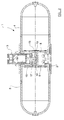
- the inflator 1 comprises a main body 2, having a diffuser 3 for delivering gas into the interior of an air-bag (not shown), as is known in the art.
- the main body 2 is substantially hollow and cylindrical in form, having first and second open ends.
- a pair of gas bottles 4,5 are attached to the open ends of the main body 2.
- the gas bottle 4 that is shown closest to the viewer in figure 1 is shown in cut-away form, so that the interior of the bottle 4 can be seen.
- the bottle 4 comprises a generally cylindrical side wall 6 and an end wall 7, which is generally planar.
- the side wall 6 and end wall 7 may be formed integrally with one another, or may be joined together in a gas-type fashion by any suitable manner, for instance by welding.
- vent aperture 8 is formed in the end wall 7 of the gas bottle 4.
- the vent aperture is generally "C"-shaped, taking the form of an arc whose ends 9 come relatively close to one another, but do not meet.
- a tab or tongue is defined within the arc shape 8, and comprises a first support 10, which is attached to the remainder of the end wall 7 by a relatively narrow connection 11, which lies between the ends 9 of the arc of the vent aperture 8.
- a further aperture 12 is formed through the connection 11. The purpose of this further aperture 12 will be discussed below.
- a rupturable foil 13 preferably of generally circular shape, is placed on the interior side of the end wall 7, and is shown in phantom in figure 1 for the purposes of clarity.
- the foil 13 completely covers the vent aperture 8, first support 10 and further aperture 12.
- the foil 13 is attached to the interior surface of the end wall 7 by any suitable means, for instance by spot welding or continuous welding. In a preferred embodiment the foil 13 is welded to the end wall 7 all, or substantially all, of the way around its periphery.
- the foil 13 is also attached to the first support 10, again preferably by welding.
- the foil 13 is attached to the first support 10 at a location 14 which is near the free end of the first support 10 (i.e. a region of the first support 10 which is remote from the connection 11 by which the first support 10 is joined to the rest of the end wall 7).
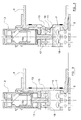
- FIG 2 a cross-sectional view of the inflator 1 is shown. It can be seen that the other gas bottle 5 has a similar arrangement of a vent aperture 8 in its end wall 7, with a rupturable foil 13 covering the vent aperture 8.
- a piston arrangement 15 having a squib 16 which, when ignited, is adapted to drive a piston head 17.
- the squib 16 is located close to the diffuser 3, and is adapted to drive the piston head 17 in a direction towards the far end of the main body 2, i.e. away from the diffuser 3.
- the piston head 17 has an outwardly-extending flange which forms a second support 18, and which extends substantially across the entire width of the central space of the main body 2.
- the second support 18 lies between the first supports 10 of the two gas bottles 4,5, thus bracing the first supports 10 and preventing the first supports 10 from moving inwardly into the central space of the main body 2.
- the second support 18 braces each support 10 at a region near its free end.
- Figures 3 and 4 show the sequence of events when the air-bag is triggered.
- Figure 3 shows the initial state of the inflator, which is discussed above.
- the squib 16 is activated, which drives (as discussed above) the piston head 17, to the right in the orientation of figures 3 and 4 .
- Figure 4 shows the situation after the piston head 17 has been driven by the ignition of the squib 16.
- the second support 18 is driven away from the region behind the first support 10, and there is therefore nothing preventing the first support 10 from moving inwardly into the interior space of the main body 2.
- the first support 10 will therefore be driven inwardly by the pressure of gas within the bottle 4. As this occurs, the narrow connection 11 by which the first support 10 is attached to the end wall 7 will preferably deform and act as a hinge as the first support 10 is driven inwardly.
- the foil 13 will be actively ruptured, as the foil 13 is attached both to the end wall 7 of the bottle 4, in a region near the first support 10, and to the first support 10 itself.
- the distance between these two points of connection will increase when the first support 10 moves inwardly into the interior space of the main body 2. This increase in distance is such that the foil 13 must rupture, as the foil 13 is formed to be insufficiently elastic to stretch by this amount without rupturing.
- the foil 13 was not connected to the first support 10, then when the first support 10 deflected inwardly the foil 13 would be able to bulge uniformly over the entire area of the vent aperture 8, thus accommodating a relatively large pressure difference before the elastic limit of the foil 13 is reached.
- the foil 13 is stretched between two points of fixation as the first support 10 is deflected inwardly, thus overcoming the elastic limit of the foil 13 much more swiftly and reliably, without such a large pressure difference being needed.
- first gas bottle 4 is shown in figures 3 and 4 , it will be appreciated that a similar or identical arrangement may be provided for the second gas bottle 5, and hence that both gas bottles 4,5 may be opened simultaneously by the driving of the piston head 17 so that the second support 18 is removed from the region between the first supports 10 of the first and second gas bottles 4,5.
- gas from the interior of the first bottle 4 will, once the foil 13 has been ruptured, be able to flow into the interior of the main body 2, and subsequently out through the diffuser 3 into the interior of an air-bag. If two gas bottles 4,5 are provided, the gases from these two bottles 4,5 may mix within the main body 2 and subsequently be introduced together into the interior of the air-bag, where they may be ignited, as is known in the art.
- Figure 5 shows a cut-away end of a gas bottle 4, before and after a foil 13 is attached to the end wall 7 of the bottle 4.
- vent aperture 8 is generally arcuate and defines a first support 10 in the form of a tab or tongue within the arc.
- a secondary aperture 12 is preferably formed between the two ends 9 of the vent aperture 8. Positioning the secondary aperture 12 in this location helps to form a line of weakness, passing generally through the two ends 9 of the vent aperture 8 and the secondary aperture 12, ensuring that the first support 10 can flex inwardly around this line of weakness when the second support 18 is removed.
- the secondary aperture 12 can also act as a safety valve, in case the pressure of gas within the bottle 4 becomes too high - the foil 13 may rupture solely in the region of the secondary aperture 12, and this may prevent the gas bottle from exploding, for instance under conditions of extremely high temperature.
- the secondary aperture 12 may be formed integrally with the vent aperture 8, so that one of the ends 9 of the vent aperture runs into the secondary aperture 12.
- the secondary aperture 12 may be omitted entirely.
- the foil 13 is shown in position.
- the foil 13 is welded around its periphery (indicated by reference numeral 19) to the end wall 7, and is also welded at a point 14 to the first support 10.
- the point 14 at which the foil 13 is attached to the first support 10 may act as a crack initiator or stress concentrator, to help initiate the rupturing of the foil 13.
- the foil 13 may be welded to the first support 10 at a single point or in a line (which may be generally parallel with, or perpendicular to, the longitudinal axis of the first support 10), or may alternatively form a square, circular or part-circular shape, or any other appropriate shape.
- the internal volume of the main body 2 can be minimised, as a small number of moving parts are required.
- vent aperture formed in the end wall of the or each gas bottle needed to be relatively large, to ensure that the foil would rupture. This in turn required a relatively large support, and a considerable amount of space was required within the main body to allow this support to move inwardly.
- the first support 10 may be formed to be relatively small, thus less space is required within the main body to allow the first support to deflect inwardly.
- the first support 10 is formed integrally with the end wall 7 of the gas bottle 4. This makes the construction of the inflator particularly 2 simple and robust.
- the first support 10 may be attached to the end wall 4, for instance by way of welding.
- embodiments of the present invention provide a compact and reliable inflator that will find application in many fields, particularly in the field of vehicle air-bags.
Landscapes
- Physics & Mathematics (AREA)
- Fluid Mechanics (AREA)
- Engineering & Computer Science (AREA)
- Mechanical Engineering (AREA)
- Air Bags (AREA)
Abstract
Description
- The present invention relates to an air-bag, such as an air-bag provided in a vehicle to provide protection for an occupant of the vehicle in the event of an accident.
- It has previously been proposed to provide air-bag inflators which incorporate one or two bottles of pressure vessels containing gas under pressure. Each bottle is initially sealed, for instance by a metal foil. The foil can be initially supported by means of a support element which is held in position against the exterior side of the foil. When the inflator is triggered the support element is moved away from the metal foil, enabling the foil to rupture under the pressure of the gas within the bottle, and enabling the gas to escape from the bottle and flow into the interior of the air-bag to inflate the air-bag.
- In known inflators of this type one bottle may contain a fuel, in the form of an oxidisable gas, and another bottle may contain an oxidising gas. When these gases escape from the gas bottles they are mixed, and may subsequently be ignited within the air-bag to complete inflation of the air-bag. As an alternative only one bottle can be used, containing suitable reactive or non-reactive gases.
-
EP1778526 andUS6612326 disclose arrangements of this type in which a support element is initially provided immediately behind a foil, and held in position by a flange of a piston head, or by a support that is arranged to be knocked out of position by a piston head. When the air-bag is to be triggered, the piston is driven so that the flange or support moves away from the region behind the support element, thus allowing the support element to move away from the foil, and so allowing the pressure of gas within the bottle to rupture the foil, pushing the support element away as this occurs. - In order for systems of this type to be effective, the foil must be relatively thin, and the pressure of gas within the bottle must be relatively high. lf the foil is too thick, or the pressure of gas within the bottle is too low, there is a risk that the foil will bulge elastically and will not rupture at the required time, particularly in low-temperature conditions.
- Other known systems do not include a movable support, and instead utilise an arrangement for actively piercing the foil. However, these systems inevitably involve additional moving parts, increasing the cost, complexity and likelihood of failure.
- It is an object of the present invention to provide an inflator which addresses at least some of the above problems.
- Accordingly, one aspect of the present invention provides an inflator for a vehicle air-bag, the inflator comprising: a container initially containing a pressurised gas, the container having a vent opening formed in a wall thereof; a rupturable element which covers the vent opening, substantially sealing the interior of the container, the rupturable element being attached to the wall of the container at at least a first location; a first support which is attached to the wall of the container and movable with respect to the wall of the container between a first configuration, in which the first support supports a region of the rupturable element and prevents the rupturable element from rupturing, and a second configuration, the rupturable element being attached to the first support at at least a second location; a second support which, in an initial configuration, supports the first support and prevents the first support from moving from the first configuration to the second configuration, and which, in a final configuration, allows the first support to move from the first configuration to the second configuration; and an activation mechanism which, when triggered, moves the second support from the initial configuration to the final configuration.
- Advantageously, when the first support is in the first configuration, there is a first distance between the first location and the second location; and when the first support is in the second configuration, there is a second distance between the first location and the second location, wherein the second distance is larger than the first distance.
- Preferably, the portion of the rupturable element that initially extends between the first location and the second location is insufficiently elastic to stretch over the second distance, so that when the first support moves from the first configuration to the second configuration, the increase in distance between the first and second locations causes the rupturable element to rupture.
- Advantageously, the activation mechanism comprises a piston element which drives the second support from the initial configuration to the final configuration.
- Conveniently, the first support may move in a hinged manner between the first configuration and the second configuration.
- Advantageously, the first support is formed integrally with the wall of the container.
- Preferably, the vent aperture partially surrounds the first support, the first support forming a tongue or tab in the wall of the container.
- Conveniently, the gap is generally "C"-shaped or "U"-shaped.
- Advantageously, the gap comprises a widened portion.
- Preferably, a further, separate aperture is formed through the wall of the container in a region that is initially covered by the rupturable element.
- Conveniently, the inflator comprises a main body with an internal space, the container being attached to the main body so that the wall of the container separates the interior of the container from the internal space.
- Advantageously, in the second configuration, the first support is deflected inwardly into the internal space.
- Preferably, the inflator is connected to deliver gas into the interior of an air-bag.
- Conveniently, the inflator comprises a second container which initially contains a second pressurised gas.
- Another aspect of the present invention provides an air-bag module containing an inflator according to any of the above.
- A further aspect of the present invention provides a vehicle containing an air-bag module according to the above.
- In order that the present invention may be more readily understood embodiments thereof will now be described, by way of example, with reference to the accompanying drawings, in which:
-
Figures 1 and2 show components of an inflator embodying the present invention; -
Figures 3 and 4 show components of the inflator offigures 1 and2 before and after triggering, respectively; and -
Figure 5 shows a part of a gas bottle forming part of an inflator embodying the present invention, before and after a rupturable foil is attached to the gas bottle. - With reference firstly to
figure 1 , components of aninflator 1 embodying the present invention are shown. Theinflator 1 comprises amain body 2, having adiffuser 3 for delivering gas into the interior of an air-bag (not shown), as is known in the art. Themain body 2 is substantially hollow and cylindrical in form, having first and second open ends. - A pair of
gas bottles main body 2. Thegas bottle 4 that is shown closest to the viewer infigure 1 is shown in cut-away form, so that the interior of thebottle 4 can be seen. Thebottle 4 comprises a generallycylindrical side wall 6 and anend wall 7, which is generally planar. Theside wall 6 andend wall 7 may be formed integrally with one another, or may be joined together in a gas-type fashion by any suitable manner, for instance by welding. - A
vent aperture 8 is formed in theend wall 7 of thegas bottle 4. In the embodiments shown infigure 1 , the vent aperture is generally "C"-shaped, taking the form of an arc whoseends 9 come relatively close to one another, but do not meet. A tab or tongue is defined within thearc shape 8, and comprises afirst support 10, which is attached to the remainder of theend wall 7 by a relativelynarrow connection 11, which lies between theends 9 of the arc of thevent aperture 8. - A
further aperture 12 is formed through theconnection 11. The purpose of thisfurther aperture 12 will be discussed below. - A
rupturable foil 13, preferably of generally circular shape, is placed on the interior side of theend wall 7, and is shown in phantom infigure 1 for the purposes of clarity. Thefoil 13 completely covers thevent aperture 8,first support 10 andfurther aperture 12. - The
foil 13 is attached to the interior surface of theend wall 7 by any suitable means, for instance by spot welding or continuous welding. In a preferred embodiment thefoil 13 is welded to theend wall 7 all, or substantially all, of the way around its periphery. - The
foil 13 is also attached to thefirst support 10, again preferably by welding. In a preferred embodiment thefoil 13 is attached to thefirst support 10 at alocation 14 which is near the free end of the first support 10 (i.e. a region of thefirst support 10 which is remote from theconnection 11 by which thefirst support 10 is joined to the rest of the end wall 7). - Referring to
figure 2 , a cross-sectional view of theinflator 1 is shown. It can be seen that theother gas bottle 5 has a similar arrangement of avent aperture 8 in itsend wall 7, with arupturable foil 13 covering thevent aperture 8. - In the space within the
main body 2 of theinflator 1, between theend walls 7 of thegas bottles piston arrangement 15 having asquib 16 which, when ignited, is adapted to drive apiston head 17. In the preferred embodiment shown infigure 2 , thesquib 16 is located close to thediffuser 3, and is adapted to drive thepiston head 17 in a direction towards the far end of themain body 2, i.e. away from thediffuser 3. - The
piston head 17 has an outwardly-extending flange which forms asecond support 18, and which extends substantially across the entire width of the central space of themain body 2. In an initial configuration, before ignition of thesquib 16, thesecond support 18 lies between thefirst supports 10 of the twogas bottles first supports 10 and preventing thefirst supports 10 from moving inwardly into the central space of themain body 2. In preferred embodiments thesecond support 18 braces each support 10 at a region near its free end. -
Figures 3 and 4 show the sequence of events when the air-bag is triggered.Figure 3 shows the initial state of the inflator, which is discussed above. At the beginning of the process thesquib 16 is activated, which drives (as discussed above) thepiston head 17, to the right in the orientation offigures 3 and 4 . -
Figure 4 shows the situation after thepiston head 17 has been driven by the ignition of thesquib 16. Thesecond support 18 is driven away from the region behind thefirst support 10, and there is therefore nothing preventing thefirst support 10 from moving inwardly into the interior space of themain body 2. - The
first support 10 will therefore be driven inwardly by the pressure of gas within thebottle 4. As this occurs, thenarrow connection 11 by which thefirst support 10 is attached to theend wall 7 will preferably deform and act as a hinge as thefirst support 10 is driven inwardly. - As this occurs, the
foil 13 will be actively ruptured, as thefoil 13 is attached both to theend wall 7 of thebottle 4, in a region near thefirst support 10, and to thefirst support 10 itself. The distance between these two points of connection will increase when thefirst support 10 moves inwardly into the interior space of themain body 2. This increase in distance is such that thefoil 13 must rupture, as thefoil 13 is formed to be insufficiently elastic to stretch by this amount without rupturing. - It will therefore be appreciated that the attachment of the
foil 13 both to thefirst support 10 and to thewall 7 of thebottle 4 near thefirst support 10 ensures that thefoil 13 is actively ruptured when thesecond support 18 is removed from thefirst support 10. - If the
foil 13 was not connected to thefirst support 10, then when thefirst support 10 deflected inwardly thefoil 13 would be able to bulge uniformly over the entire area of thevent aperture 8, thus accommodating a relatively large pressure difference before the elastic limit of thefoil 13 is reached. However, in embodiments of the present invention thefoil 13 is stretched between two points of fixation as thefirst support 10 is deflected inwardly, thus overcoming the elastic limit of thefoil 13 much more swiftly and reliably, without such a large pressure difference being needed. - As only the
first gas bottle 4 is shown infigures 3 and 4 , it will be appreciated that a similar or identical arrangement may be provided for thesecond gas bottle 5, and hence that bothgas bottles piston head 17 so that thesecond support 18 is removed from the region between the first supports 10 of the first andsecond gas bottles - The skilled person will appreciate that gas from the interior of the
first bottle 4 will, once thefoil 13 has been ruptured, be able to flow into the interior of themain body 2, and subsequently out through thediffuser 3 into the interior of an air-bag. If twogas bottles bottles main body 2 and subsequently be introduced together into the interior of the air-bag, where they may be ignited, as is known in the art. - It will be appreciated that the embodiments discussed above allow for consistent and reliable opening of gas bottles with a minimum number of moving parts.
-
Figure 5 shows a cut-away end of agas bottle 4, before and after afoil 13 is attached to theend wall 7 of thebottle 4. - As can be seen in the right-hand portion of
figure 5 , thevent aperture 8 is generally arcuate and defines afirst support 10 in the form of a tab or tongue within the arc. - A
secondary aperture 12 is preferably formed between the two ends 9 of thevent aperture 8. Positioning thesecondary aperture 12 in this location helps to form a line of weakness, passing generally through the two ends 9 of thevent aperture 8 and thesecondary aperture 12, ensuring that thefirst support 10 can flex inwardly around this line of weakness when thesecond support 18 is removed. - The
secondary aperture 12 can also act as a safety valve, in case the pressure of gas within thebottle 4 becomes too high - thefoil 13 may rupture solely in the region of thesecondary aperture 12, and this may prevent the gas bottle from exploding, for instance under conditions of extremely high temperature. In alternative designs thesecondary aperture 12 may be formed integrally with thevent aperture 8, so that one of theends 9 of the vent aperture runs into thesecondary aperture 12. Alternatively, thesecondary aperture 12 may be omitted entirely. - In the left-hand portion of
figure 5 thefoil 13 is shown in position. Thefoil 13 is welded around its periphery (indicated by reference numeral 19) to theend wall 7, and is also welded at apoint 14 to thefirst support 10. Thepoint 14 at which thefoil 13 is attached to thefirst support 10 may act as a crack initiator or stress concentrator, to help initiate the rupturing of thefoil 13. Thefoil 13 may be welded to thefirst support 10 at a single point or in a line (which may be generally parallel with, or perpendicular to, the longitudinal axis of the first support 10), or may alternatively form a square, circular or part-circular shape, or any other appropriate shape. - It has been found that systems embodying the present invention allow the use of a thicker foil. Current designs of inflator use a foil formed from 0.15mm lnconel (TM), and if a thicker foil is used then the foil will not rupture reliably. However, by using embodiments of the present invention it has been found that a 0.2mm lnconel foil may be used, and the foil may be ruptured reliably, when the inflator is triggered. This is advantageous because, for example, a thicker foil will be more robust against pressure and temperature cycling, and the useful lifetime of the inflator will therefore be extended.
- In addition, the internal volume of the
main body 2 can be minimised, as a small number of moving parts are required. - Further, in previous designs the vent aperture formed in the end wall of the or each gas bottle needed to be relatively large, to ensure that the foil would rupture. This in turn required a relatively large support, and a considerable amount of space was required within the main body to allow this support to move inwardly.
- By contrast, in embodiments of the present invention the
first support 10 may be formed to be relatively small, thus less space is required within the main body to allow the first support to deflect inwardly. - The attachment of the
first support 10 to thewall 7 of thegas bottle 4 reduces the number of components of theinflator 2 and simplifies the design. In preferred embodiments of the present invention, thefirst support 10 is formed integrally with theend wall 7 of thegas bottle 4. This makes the construction of the inflator particularly 2 simple and robust. However, in other embodiments thefirst support 10 may be attached to theend wall 4, for instance by way of welding. - It will be appreciated that embodiments of the present invention provide a compact and reliable inflator that will find application in many fields, particularly in the field of vehicle air-bags.
- When used in this specification and claims, the terms "comprises" and "comprising" and variations thereof mean that the specified features, steps or integers are included. The terms are not to be interpreted to exclude the presence of other features, steps or components.
- The features disclosed in the foregoing description, or the following claims, or the accompanying drawings, expressed in their specific forms or in terms of a means for performing the disclosed function, or a method or process for attaining the disclosed result, as appropriate, may, separately, or in any combination of such features, be utilised for realising the invention in diverse forms thereof.
Claims (15)
- An inflator for a vehicle air-bag, the inflator comprising:a container initially containing a pressurised gas, the container having a vent opening formed in a wall thereof;a rupturable element which covers the vent opening, substantially sealing the interior of the container, the rupturable element being attached to the wall of the container at at least a first location;a first support which is attached to the wall of the container and movable with respect to the wall of the container between a first configuration, in which the first support supports a region of the rupturable element and prevents the rupturable element from rupturing, and a second configuration, the rupturable element being attached to the first support at at least a second location;a second support which, in an initial configuration, supports the first support and prevents the first support from moving from the first configuration to the second configuration, and which, in a final configuration, allows the first support to move from the first configuration to the second configuration; andan activation mechanism which, when triggered, moves the second support from the initial configuration to the final configuration.
- An inflator according to claim 1 wherein:when the first support is in the first configuration, there is a first distance between the first location and the second location; andwhen the first support is in the second configuration, there is a second distance between the first location and the second location, wherein the second distance is larger than the first distance.
- An inflator according to claim 2 wherein the portion of the rupturable element that initially extends between the first location and the second location is insufficiently elastic to stretch over the second distance, so that when the first support moves from the first configuration to the second configuration, the increase in distance between the first and second locations causes the rupturable element to rupture.
- An inflator according to any preceding claim wherein the activation mechanism comprises a piston element which drives the second support from the initial configuration to the final configuration.
- An inflator according to any preceding claim wherein the first support may move in a hinged manner between the first configuration and the second configuration.
- An inflator according to any preceding claim, wherein the first support is formed integrally with the wall of the container.
- An inflator according to claim 6, wherein the vent aperture partially surrounds the first support, the first support forming a tongue or tab in the wall of the container.
- An inflator according to claim 7, wherein the gap is generally "C"-shaped or "U"-shaped.
- An inflator according to claim 7 or 8, wherein the gap comprises a widened portion.
- An inflator according to any one of claims 7 to 9, wherein a further, separate aperture is formed through the wall of the container in a region that is initially covered by the rupturable element.
- An inflator according to any preceding claim comprising a main body with an internal space, the container being attached to the main body so that the wall of the container separates the interior of the container from the internal space.
- An inflator according to claim 11 wherein, in the second configuration, the first support is deflected inwardly into the internal space.
- An inflator according to any preceding claim, connected to deliver gas into the interior of an air-bag.
- An air-bag module containing an inflator according to any preceding claim.
- A vehicle containing an air-bag module according to claim 14.
Priority Applications (5)
| Application Number | Priority Date | Filing Date | Title |
|---|---|---|---|
| EP20110167438 EP2527210B1 (en) | 2011-05-25 | 2011-05-25 | An inflator for an air bag |
| CN201280024957.9A CN103547487B (en) | 2011-05-25 | 2012-05-22 | Inflator for an airbag, air bag module and comprise the vehicle of this kind of air bag module |
| US14/117,074 US9365183B2 (en) | 2011-05-25 | 2012-05-22 | Inflator for an airbag, an airbag module and a vehicle comprising such an airbag module |
| JP2014512795A JP5872686B2 (en) | 2011-05-25 | 2012-05-22 | Inflator for airbag, airbag module, and vehicle including such airbag module |
| PCT/SE2012/050550 WO2012161647A1 (en) | 2011-05-25 | 2012-05-22 | An inflator for an airbag, an airbag module and a vehicle comprising such an airbag module. |
Applications Claiming Priority (1)
| Application Number | Priority Date | Filing Date | Title |
|---|---|---|---|
| EP20110167438 EP2527210B1 (en) | 2011-05-25 | 2011-05-25 | An inflator for an air bag |
Publications (2)
| Publication Number | Publication Date |
|---|---|
| EP2527210A1 true EP2527210A1 (en) | 2012-11-28 |
| EP2527210B1 EP2527210B1 (en) | 2013-12-25 |
Family
ID=44925155
Family Applications (1)
| Application Number | Title | Priority Date | Filing Date |
|---|---|---|---|
| EP20110167438 Active EP2527210B1 (en) | 2011-05-25 | 2011-05-25 | An inflator for an air bag |
Country Status (5)
| Country | Link |
|---|---|
| US (1) | US9365183B2 (en) |
| EP (1) | EP2527210B1 (en) |
| JP (1) | JP5872686B2 (en) |
| CN (1) | CN103547487B (en) |
| WO (1) | WO2012161647A1 (en) |
Cited By (2)
| Publication number | Priority date | Publication date | Assignee | Title |
|---|---|---|---|---|
| FR3041093A1 (en) * | 2015-09-15 | 2017-03-17 | Autoliv Dev | GAS GENERATOR |
| FR3051167A1 (en) * | 2016-05-13 | 2017-11-17 | Autoliv Dev | GAS GENERATOR WITH FLOW CONTROL DEVICE |
Families Citing this family (6)
| Publication number | Priority date | Publication date | Assignee | Title |
|---|---|---|---|---|
| JP6095463B2 (en) * | 2013-04-22 | 2017-03-15 | 株式会社ダイセル | Gas generator |
| DE102013219905A1 (en) * | 2013-10-01 | 2015-04-02 | Robert Bosch Gmbh | Apparatus and method for activating an airbag for a vehicle and airbag system for a vehicle |
| DE102014201495B4 (en) * | 2013-12-12 | 2019-01-17 | Joyson Safety Systems Germany Gmbh | Gas generator assembly for an airbag module |
| EP3371492B1 (en) | 2015-11-06 | 2021-07-07 | Oklahoma Safety Equipment Company, Inc. | Rupture disc device and method of assembly thereof |
| FR3134774A1 (en) * | 2022-04-20 | 2023-10-27 | Autoliv Development Ab | Gas generator comprising reactive gases |
| FR3135237B1 (en) | 2022-05-04 | 2024-12-06 | Autoliv Dev | Gas generator with a gas chamber and a sealing cap |
Citations (5)
| Publication number | Priority date | Publication date | Assignee | Title |
|---|---|---|---|---|
| GB2281228A (en) * | 1993-08-26 | 1995-03-01 | Autoliv Dev | A gas generator for an air-bag |
| US6612326B2 (en) | 2000-12-18 | 2003-09-02 | Breed Automotive Technology, Inc. | Inflator |
| GB2416199A (en) * | 2004-07-12 | 2006-01-18 | Autoliv Dev | Inflator for a vehicle airbag |
| GB2417066A (en) * | 2004-08-13 | 2006-02-15 | Autoliv Dev | Inflator for an air-bag |
| GB2448300A (en) * | 2007-04-12 | 2008-10-15 | Autoliv Dev | Igniter tube in air bag inflator apparatus |
Family Cites Families (14)
| Publication number | Priority date | Publication date | Assignee | Title |
|---|---|---|---|---|
| US5063958A (en) * | 1991-01-24 | 1991-11-12 | The United States Of Americas As Represented By The Secretary Of The Navy | Burst diaphragm sequence valve |
| DE19540618A1 (en) | 1995-10-31 | 1997-05-07 | Autoliv Dev | Device for flowing pressurized gas into a vehicle safety device |
| US5947143A (en) | 1997-02-28 | 1999-09-07 | Breed Automotive Technology, Inc. | Fast acting deployment device for high pressure vessels |
| DE19739375B4 (en) * | 1997-09-09 | 2005-07-28 | Welz Industrieprodukte Gmbh | Opening device for a gas pressure tank of an airbag |
| DE19951672C2 (en) | 1999-10-27 | 2003-09-11 | Petri Dn Gmbh Inflator Systems | Hybrid gas generator |
| DE10031749A1 (en) | 2000-06-29 | 2002-01-10 | Welz Industrieprodukte Gmbh | Cold gas generator |
| DE20104433U1 (en) * | 2001-03-15 | 2001-06-13 | Breed Automotive Technology, Inc., Lakeland, Fla. | Device for inflating an airbag |
| DE10112558B4 (en) * | 2001-03-15 | 2006-04-20 | Key Safety Systems, Inc., Sterling Heights | Device for filling an airbag |
| GB2373310B (en) * | 2001-03-15 | 2005-02-02 | Autoliv Dev | Improvements in or relating to an inflator |
| US7695009B2 (en) * | 2005-01-13 | 2010-04-13 | Autoliv Development Ab | Inflator for an air-bag |
| DE602005010730D1 (en) * | 2005-12-20 | 2008-12-11 | Key Safety Systems Inc | Gas generator with throttle for variable gas flow |
| EP1800972B1 (en) * | 2005-12-20 | 2008-10-29 | Key Safety Systems, Inc. | Inflator having an improved closure cap |
| EP2229296B1 (en) * | 2008-01-15 | 2012-01-04 | Autoliv Development AB | An inflator for an air-bag |
| CN101574953A (en) * | 2009-06-08 | 2009-11-11 | 王运韬 | Active and passive airbag inflatable gas generator for environment-friendly automobile |
-
2011
- 2011-05-25 EP EP20110167438 patent/EP2527210B1/en active Active
-
2012
- 2012-05-22 JP JP2014512795A patent/JP5872686B2/en active Active
- 2012-05-22 US US14/117,074 patent/US9365183B2/en active Active
- 2012-05-22 CN CN201280024957.9A patent/CN103547487B/en active Active
- 2012-05-22 WO PCT/SE2012/050550 patent/WO2012161647A1/en not_active Ceased
Patent Citations (6)
| Publication number | Priority date | Publication date | Assignee | Title |
|---|---|---|---|---|
| GB2281228A (en) * | 1993-08-26 | 1995-03-01 | Autoliv Dev | A gas generator for an air-bag |
| US6612326B2 (en) | 2000-12-18 | 2003-09-02 | Breed Automotive Technology, Inc. | Inflator |
| GB2416199A (en) * | 2004-07-12 | 2006-01-18 | Autoliv Dev | Inflator for a vehicle airbag |
| GB2417066A (en) * | 2004-08-13 | 2006-02-15 | Autoliv Dev | Inflator for an air-bag |
| EP1778526A1 (en) | 2004-08-13 | 2007-05-02 | Autoliv Development Ab | An inflator for an air-bag |
| GB2448300A (en) * | 2007-04-12 | 2008-10-15 | Autoliv Dev | Igniter tube in air bag inflator apparatus |
Cited By (2)
| Publication number | Priority date | Publication date | Assignee | Title |
|---|---|---|---|---|
| FR3041093A1 (en) * | 2015-09-15 | 2017-03-17 | Autoliv Dev | GAS GENERATOR |
| FR3051167A1 (en) * | 2016-05-13 | 2017-11-17 | Autoliv Dev | GAS GENERATOR WITH FLOW CONTROL DEVICE |
Also Published As
| Publication number | Publication date |
|---|---|
| CN103547487A (en) | 2014-01-29 |
| EP2527210B1 (en) | 2013-12-25 |
| WO2012161647A1 (en) | 2012-11-29 |
| JP5872686B2 (en) | 2016-03-01 |
| JP2014515332A (en) | 2014-06-30 |
| US20140332092A1 (en) | 2014-11-13 |
| CN103547487B (en) | 2016-12-14 |
| US9365183B2 (en) | 2016-06-14 |
Similar Documents
| Publication | Publication Date | Title |
|---|---|---|
| US9365183B2 (en) | Inflator for an airbag, an airbag module and a vehicle comprising such an airbag module | |
| US8651520B2 (en) | Inflator | |
| US5542702A (en) | Pressurized gas inflator for vehicle occupant protection systems | |
| CN1944116B (en) | Airbag inflator | |
| JPH08253100A (en) | Hybrid gas generator for safety system in automobile | |
| US5601309A (en) | Hybrid gas generator for safety systems in road vehicles | |
| US9463767B2 (en) | Bursting diaphragm, especially for an inflator, inflator, airbag module and vehicle safety system | |
| JPH06206512A (en) | Liquid gas generator for crash protecting cushion expandable to prevent automobile passenger from injury | |
| US20090273168A1 (en) | Vehicle occupant protection system | |
| EP1782861A1 (en) | Fire extinguishing apparatus and method with gas generator and extinguishing agent | |
| JP2005520734A (en) | Dual-flow inflator for vehicle airbag systems | |
| EP2229296B1 (en) | An inflator for an air-bag | |
| US8459693B1 (en) | Gas generator with supported sealing membrane | |
| US20160159314A1 (en) | Combustion chamber comprising an opening device for a compressed gas tank of a hybrid inflator, hybrid inlfator, airbag module, vehicle safety system and method of discharging fluid from an inflator | |
| EP3209921B1 (en) | Tube cutter | |
| EP0811533A2 (en) | Integral projectile squib for air bag inflators | |
| US6981718B2 (en) | Projectile firing barrel | |
| EP1453706B1 (en) | Opening device for a cold gas inflator | |
| US9834169B2 (en) | Device and method for activating a passenger protection means for a vehicle, manufacturing method for manufacturing the device, and passenger protection system for a vehicle | |
| JP3088400B2 (en) | Vehicle airbag device | |
| US20060006632A1 (en) | Gas generator for air bag | |
| US20070176404A1 (en) | Stored gas inflator | |
| US20050029788A1 (en) | Inflator | |
| US20040227337A1 (en) | Inflation device for a vehicle occupant restraint system | |
| WO2011024203A2 (en) | Airbag inflator system |
Legal Events
| Date | Code | Title | Description |
|---|---|---|---|
| PUAI | Public reference made under article 153(3) epc to a published international application that has entered the european phase |
Free format text: ORIGINAL CODE: 0009012 |
|
| AK | Designated contracting states |
Kind code of ref document: A1 Designated state(s): AL AT BE BG CH CY CZ DE DK EE ES FI FR GB GR HR HU IE IS IT LI LT LU LV MC MK MT NL NO PL PT RO RS SE SI SK SM TR |
|
| AX | Request for extension of the european patent |
Extension state: BA ME |
|
| 17P | Request for examination filed |
Effective date: 20130521 |
|
| RIC1 | Information provided on ipc code assigned before grant |
Ipc: B60R 21/264 20060101AFI20130605BHEP |
|
| GRAP | Despatch of communication of intention to grant a patent |
Free format text: ORIGINAL CODE: EPIDOSNIGR1 |
|
| INTG | Intention to grant announced |
Effective date: 20130717 |
|
| GRAS | Grant fee paid |
Free format text: ORIGINAL CODE: EPIDOSNIGR3 |
|
| GRAA | (expected) grant |
Free format text: ORIGINAL CODE: 0009210 |
|
| AK | Designated contracting states |
Kind code of ref document: B1 Designated state(s): AL AT BE BG CH CY CZ DE DK EE ES FI FR GB GR HR HU IE IS IT LI LT LU LV MC MK MT NL NO PL PT RO RS SE SI SK SM TR |
|
| REG | Reference to a national code |
Ref country code: GB Ref legal event code: FG4D |
|
| REG | Reference to a national code |
Ref country code: CH Ref legal event code: EP |
|
| REG | Reference to a national code |
Ref country code: AT Ref legal event code: REF Ref document number: 646427 Country of ref document: AT Kind code of ref document: T Effective date: 20140115 |
|
| REG | Reference to a national code |
Ref country code: IE Ref legal event code: FG4D |
|
| REG | Reference to a national code |
Ref country code: DE Ref legal event code: R096 Ref document number: 602011004304 Country of ref document: DE Effective date: 20140213 |
|
| PG25 | Lapsed in a contracting state [announced via postgrant information from national office to epo] |
Ref country code: NO Free format text: LAPSE BECAUSE OF FAILURE TO SUBMIT A TRANSLATION OF THE DESCRIPTION OR TO PAY THE FEE WITHIN THE PRESCRIBED TIME-LIMIT Effective date: 20140325 Ref country code: FI Free format text: LAPSE BECAUSE OF FAILURE TO SUBMIT A TRANSLATION OF THE DESCRIPTION OR TO PAY THE FEE WITHIN THE PRESCRIBED TIME-LIMIT Effective date: 20131225 Ref country code: HR Free format text: LAPSE BECAUSE OF FAILURE TO SUBMIT A TRANSLATION OF THE DESCRIPTION OR TO PAY THE FEE WITHIN THE PRESCRIBED TIME-LIMIT Effective date: 20131225 Ref country code: SE Free format text: LAPSE BECAUSE OF FAILURE TO SUBMIT A TRANSLATION OF THE DESCRIPTION OR TO PAY THE FEE WITHIN THE PRESCRIBED TIME-LIMIT Effective date: 20131225 Ref country code: LT Free format text: LAPSE BECAUSE OF FAILURE TO SUBMIT A TRANSLATION OF THE DESCRIPTION OR TO PAY THE FEE WITHIN THE PRESCRIBED TIME-LIMIT Effective date: 20131225 |
|
| REG | Reference to a national code |
Ref country code: NL Ref legal event code: VDEP Effective date: 20131225 |
|
| REG | Reference to a national code |
Ref country code: AT Ref legal event code: MK05 Ref document number: 646427 Country of ref document: AT Kind code of ref document: T Effective date: 20131225 |
|
| REG | Reference to a national code |
Ref country code: LT Ref legal event code: MG4D |
|
| PG25 | Lapsed in a contracting state [announced via postgrant information from national office to epo] |
Ref country code: LV Free format text: LAPSE BECAUSE OF FAILURE TO SUBMIT A TRANSLATION OF THE DESCRIPTION OR TO PAY THE FEE WITHIN THE PRESCRIBED TIME-LIMIT Effective date: 20131225 Ref country code: RS Free format text: LAPSE BECAUSE OF FAILURE TO SUBMIT A TRANSLATION OF THE DESCRIPTION OR TO PAY THE FEE WITHIN THE PRESCRIBED TIME-LIMIT Effective date: 20131225 |
|
| PG25 | Lapsed in a contracting state [announced via postgrant information from national office to epo] |
Ref country code: BE Free format text: LAPSE BECAUSE OF FAILURE TO SUBMIT A TRANSLATION OF THE DESCRIPTION OR TO PAY THE FEE WITHIN THE PRESCRIBED TIME-LIMIT Effective date: 20131225 Ref country code: EE Free format text: LAPSE BECAUSE OF FAILURE TO SUBMIT A TRANSLATION OF THE DESCRIPTION OR TO PAY THE FEE WITHIN THE PRESCRIBED TIME-LIMIT Effective date: 20131225 Ref country code: IS Free format text: LAPSE BECAUSE OF FAILURE TO SUBMIT A TRANSLATION OF THE DESCRIPTION OR TO PAY THE FEE WITHIN THE PRESCRIBED TIME-LIMIT Effective date: 20140425 |
|
| PG25 | Lapsed in a contracting state [announced via postgrant information from national office to epo] |
Ref country code: CY Free format text: LAPSE BECAUSE OF FAILURE TO SUBMIT A TRANSLATION OF THE DESCRIPTION OR TO PAY THE FEE WITHIN THE PRESCRIBED TIME-LIMIT Effective date: 20131225 Ref country code: NL Free format text: LAPSE BECAUSE OF FAILURE TO SUBMIT A TRANSLATION OF THE DESCRIPTION OR TO PAY THE FEE WITHIN THE PRESCRIBED TIME-LIMIT Effective date: 20131225 Ref country code: RO Free format text: LAPSE BECAUSE OF FAILURE TO SUBMIT A TRANSLATION OF THE DESCRIPTION OR TO PAY THE FEE WITHIN THE PRESCRIBED TIME-LIMIT Effective date: 20131225 Ref country code: SK Free format text: LAPSE BECAUSE OF FAILURE TO SUBMIT A TRANSLATION OF THE DESCRIPTION OR TO PAY THE FEE WITHIN THE PRESCRIBED TIME-LIMIT Effective date: 20131225 Ref country code: AT Free format text: LAPSE BECAUSE OF FAILURE TO SUBMIT A TRANSLATION OF THE DESCRIPTION OR TO PAY THE FEE WITHIN THE PRESCRIBED TIME-LIMIT Effective date: 20131225 Ref country code: PT Free format text: LAPSE BECAUSE OF FAILURE TO SUBMIT A TRANSLATION OF THE DESCRIPTION OR TO PAY THE FEE WITHIN THE PRESCRIBED TIME-LIMIT Effective date: 20140428 Ref country code: ES Free format text: LAPSE BECAUSE OF FAILURE TO SUBMIT A TRANSLATION OF THE DESCRIPTION OR TO PAY THE FEE WITHIN THE PRESCRIBED TIME-LIMIT Effective date: 20131225 Ref country code: CZ Free format text: LAPSE BECAUSE OF FAILURE TO SUBMIT A TRANSLATION OF THE DESCRIPTION OR TO PAY THE FEE WITHIN THE PRESCRIBED TIME-LIMIT Effective date: 20131225 |
|
| REG | Reference to a national code |
Ref country code: DE Ref legal event code: R097 Ref document number: 602011004304 Country of ref document: DE |
|
| PG25 | Lapsed in a contracting state [announced via postgrant information from national office to epo] |
Ref country code: DK Free format text: LAPSE BECAUSE OF FAILURE TO SUBMIT A TRANSLATION OF THE DESCRIPTION OR TO PAY THE FEE WITHIN THE PRESCRIBED TIME-LIMIT Effective date: 20131225 |
|
| PLBE | No opposition filed within time limit |
Free format text: ORIGINAL CODE: 0009261 |
|
| STAA | Information on the status of an ep patent application or granted ep patent |
Free format text: STATUS: NO OPPOSITION FILED WITHIN TIME LIMIT |
|
| PG25 | Lapsed in a contracting state [announced via postgrant information from national office to epo] |
Ref country code: PL Free format text: LAPSE BECAUSE OF FAILURE TO SUBMIT A TRANSLATION OF THE DESCRIPTION OR TO PAY THE FEE WITHIN THE PRESCRIBED TIME-LIMIT Effective date: 20131225 |
|
| 26N | No opposition filed |
Effective date: 20140926 |
|
| PG25 | Lapsed in a contracting state [announced via postgrant information from national office to epo] |
Ref country code: LU Free format text: LAPSE BECAUSE OF FAILURE TO SUBMIT A TRANSLATION OF THE DESCRIPTION OR TO PAY THE FEE WITHIN THE PRESCRIBED TIME-LIMIT Effective date: 20140525 |
|
| REG | Reference to a national code |
Ref country code: CH Ref legal event code: PL |
|
| REG | Reference to a national code |
Ref country code: DE Ref legal event code: R097 Ref document number: 602011004304 Country of ref document: DE Effective date: 20140926 |
|
| PG25 | Lapsed in a contracting state [announced via postgrant information from national office to epo] |
Ref country code: CH Free format text: LAPSE BECAUSE OF NON-PAYMENT OF DUE FEES Effective date: 20140531 Ref country code: LI Free format text: LAPSE BECAUSE OF NON-PAYMENT OF DUE FEES Effective date: 20140531 Ref country code: MC Free format text: LAPSE BECAUSE OF FAILURE TO SUBMIT A TRANSLATION OF THE DESCRIPTION OR TO PAY THE FEE WITHIN THE PRESCRIBED TIME-LIMIT Effective date: 20131225 |
|
| REG | Reference to a national code |
Ref country code: IE Ref legal event code: MM4A |
|
| PG25 | Lapsed in a contracting state [announced via postgrant information from national office to epo] |
Ref country code: IE Free format text: LAPSE BECAUSE OF NON-PAYMENT OF DUE FEES Effective date: 20140525 |
|
| PG25 | Lapsed in a contracting state [announced via postgrant information from national office to epo] |
Ref country code: SI Free format text: LAPSE BECAUSE OF FAILURE TO SUBMIT A TRANSLATION OF THE DESCRIPTION OR TO PAY THE FEE WITHIN THE PRESCRIBED TIME-LIMIT Effective date: 20131225 |
|
| GBPC | Gb: european patent ceased through non-payment of renewal fee |
Effective date: 20150525 |
|
| PG25 | Lapsed in a contracting state [announced via postgrant information from national office to epo] |
Ref country code: MT Free format text: LAPSE BECAUSE OF FAILURE TO SUBMIT A TRANSLATION OF THE DESCRIPTION OR TO PAY THE FEE WITHIN THE PRESCRIBED TIME-LIMIT Effective date: 20131225 |
|
| PG25 | Lapsed in a contracting state [announced via postgrant information from national office to epo] |
Ref country code: GB Free format text: LAPSE BECAUSE OF NON-PAYMENT OF DUE FEES Effective date: 20150525 Ref country code: SM Free format text: LAPSE BECAUSE OF FAILURE TO SUBMIT A TRANSLATION OF THE DESCRIPTION OR TO PAY THE FEE WITHIN THE PRESCRIBED TIME-LIMIT Effective date: 20131225 |
|
| REG | Reference to a national code |
Ref country code: FR Ref legal event code: PLFP Year of fee payment: 6 |
|
| PG25 | Lapsed in a contracting state [announced via postgrant information from national office to epo] |
Ref country code: BG Free format text: LAPSE BECAUSE OF FAILURE TO SUBMIT A TRANSLATION OF THE DESCRIPTION OR TO PAY THE FEE WITHIN THE PRESCRIBED TIME-LIMIT Effective date: 20131225 Ref country code: IT Free format text: LAPSE BECAUSE OF FAILURE TO SUBMIT A TRANSLATION OF THE DESCRIPTION OR TO PAY THE FEE WITHIN THE PRESCRIBED TIME-LIMIT Effective date: 20131225 Ref country code: GR Free format text: LAPSE BECAUSE OF FAILURE TO SUBMIT A TRANSLATION OF THE DESCRIPTION OR TO PAY THE FEE WITHIN THE PRESCRIBED TIME-LIMIT Effective date: 20140326 |
|
| PG25 | Lapsed in a contracting state [announced via postgrant information from national office to epo] |
Ref country code: HU Free format text: LAPSE BECAUSE OF FAILURE TO SUBMIT A TRANSLATION OF THE DESCRIPTION OR TO PAY THE FEE WITHIN THE PRESCRIBED TIME-LIMIT; INVALID AB INITIO Effective date: 20110525 Ref country code: TR Free format text: LAPSE BECAUSE OF FAILURE TO SUBMIT A TRANSLATION OF THE DESCRIPTION OR TO PAY THE FEE WITHIN THE PRESCRIBED TIME-LIMIT Effective date: 20131225 |
|
| REG | Reference to a national code |
Ref country code: FR Ref legal event code: PLFP Year of fee payment: 7 |
|
| REG | Reference to a national code |
Ref country code: FR Ref legal event code: PLFP Year of fee payment: 8 |
|
| PG25 | Lapsed in a contracting state [announced via postgrant information from national office to epo] |
Ref country code: MK Free format text: LAPSE BECAUSE OF FAILURE TO SUBMIT A TRANSLATION OF THE DESCRIPTION OR TO PAY THE FEE WITHIN THE PRESCRIBED TIME-LIMIT Effective date: 20131225 |
|
| PG25 | Lapsed in a contracting state [announced via postgrant information from national office to epo] |
Ref country code: AL Free format text: LAPSE BECAUSE OF FAILURE TO SUBMIT A TRANSLATION OF THE DESCRIPTION OR TO PAY THE FEE WITHIN THE PRESCRIBED TIME-LIMIT Effective date: 20131225 |
|
| PGFP | Annual fee paid to national office [announced via postgrant information from national office to epo] |
Ref country code: DE Payment date: 20250528 Year of fee payment: 15 |
|
| PGFP | Annual fee paid to national office [announced via postgrant information from national office to epo] |
Ref country code: FR Payment date: 20250526 Year of fee payment: 15 |