EP2527165A2 - Tire tread and truck tire - Google Patents
Tire tread and truck tire Download PDFInfo
- Publication number
- EP2527165A2 EP2527165A2 EP12168876A EP12168876A EP2527165A2 EP 2527165 A2 EP2527165 A2 EP 2527165A2 EP 12168876 A EP12168876 A EP 12168876A EP 12168876 A EP12168876 A EP 12168876A EP 2527165 A2 EP2527165 A2 EP 2527165A2
- Authority
- EP
- European Patent Office
- Prior art keywords
- shoulder
- tire tread
- tire
- sipes
- sipe
- Prior art date
- Legal status (The legal status is an assumption and is not a legal conclusion. Google has not performed a legal analysis and makes no representation as to the accuracy of the status listed.)
- Withdrawn
Links
- 230000009286 beneficial effect Effects 0.000 description 1
- 230000001419 dependent effect Effects 0.000 description 1
- 230000001788 irregular Effects 0.000 description 1
- 230000003278 mimic effect Effects 0.000 description 1
- 238000005096 rolling process Methods 0.000 description 1
- 239000011800 void material Substances 0.000 description 1
Images



Classifications
-
- B—PERFORMING OPERATIONS; TRANSPORTING
- B60—VEHICLES IN GENERAL
- B60C—VEHICLE TYRES; TYRE INFLATION; TYRE CHANGING; CONNECTING VALVES TO INFLATABLE ELASTIC BODIES IN GENERAL; DEVICES OR ARRANGEMENTS RELATED TO TYRES
- B60C11/00—Tyre tread bands; Tread patterns; Anti-skid inserts
- B60C11/03—Tread patterns
- B60C11/0306—Patterns comprising block rows or discontinuous ribs
-
- B—PERFORMING OPERATIONS; TRANSPORTING
- B60—VEHICLES IN GENERAL
- B60C—VEHICLE TYRES; TYRE INFLATION; TYRE CHANGING; CONNECTING VALVES TO INFLATABLE ELASTIC BODIES IN GENERAL; DEVICES OR ARRANGEMENTS RELATED TO TYRES
- B60C11/00—Tyre tread bands; Tread patterns; Anti-skid inserts
- B60C11/03—Tread patterns
- B60C11/0327—Tread patterns characterised by special properties of the tread pattern
- B60C11/0332—Tread patterns characterised by special properties of the tread pattern by the footprint-ground contacting area of the tyre tread
-
- B—PERFORMING OPERATIONS; TRANSPORTING
- B60—VEHICLES IN GENERAL
- B60C—VEHICLE TYRES; TYRE INFLATION; TYRE CHANGING; CONNECTING VALVES TO INFLATABLE ELASTIC BODIES IN GENERAL; DEVICES OR ARRANGEMENTS RELATED TO TYRES
- B60C11/00—Tyre tread bands; Tread patterns; Anti-skid inserts
- B60C11/03—Tread patterns
- B60C2011/0337—Tread patterns characterised by particular design features of the pattern
- B60C2011/0339—Grooves
- B60C2011/0341—Circumferential grooves
- B60C2011/0348—Narrow grooves, i.e. having a width of less than 4 mm
-
- B—PERFORMING OPERATIONS; TRANSPORTING
- B60—VEHICLES IN GENERAL
- B60C—VEHICLE TYRES; TYRE INFLATION; TYRE CHANGING; CONNECTING VALVES TO INFLATABLE ELASTIC BODIES IN GENERAL; DEVICES OR ARRANGEMENTS RELATED TO TYRES
- B60C11/00—Tyre tread bands; Tread patterns; Anti-skid inserts
- B60C11/03—Tread patterns
- B60C11/12—Tread patterns characterised by the use of narrow slits or incisions, e.g. sipes
- B60C11/1204—Tread patterns characterised by the use of narrow slits or incisions, e.g. sipes with special shape of the sipe
- B60C2011/1209—Tread patterns characterised by the use of narrow slits or incisions, e.g. sipes with special shape of the sipe straight at the tread surface
-
- B—PERFORMING OPERATIONS; TRANSPORTING
- B60—VEHICLES IN GENERAL
- B60C—VEHICLE TYRES; TYRE INFLATION; TYRE CHANGING; CONNECTING VALVES TO INFLATABLE ELASTIC BODIES IN GENERAL; DEVICES OR ARRANGEMENTS RELATED TO TYRES
- B60C2200/00—Tyres specially adapted for particular applications
- B60C2200/06—Tyres specially adapted for particular applications for heavy duty vehicles
Definitions
- the invention relates generally to a tire tread which may be used with a regional tire for a commercial truck and, more specifically, to a tread configuration for tires intended for slippery or even winter driving conditions.
- the invention relates to a tire tread in accordance with claim 1 and to a tire comprising such a tread in accordance with claim 15.
- a tire in one aspect of the invention, includes a circumferential tire tread having a central region and first and second shoulder regions adjacent the central region.
- a circumferential array of spaced apart shoulder sipes is formed within one or both of the shoulder regions, each of the shoulder sipes having a depth in an unworn tire tread condition within a depth range of from 1 mm to 3.5 mm, and each shoulder sipe having a longitudinal axis oriented in an axial direction within a range of between +/- 20 degrees of the tire axial direction.
- the shoulder sipes may extend in an axial direction and exclusively reside in one or both of the shoulder region(s) of the tire tread.
- the shoulder sipes may each include a first and a second straight segment intersecting at an end-to-end intersection with respect to each other at an intersection angle.
- the first and second straight segments of each shoulder sipe may incline in opposite directions from the end-to-end intersection, and the end-to-end intersection, of each shoulder sipe may be located at a circumferential shoulder groove within a respective shoulder region.
- shoulder groove fingers may alternate with the shoulder sipes along the circumferential direction of the tread in one or both of the shoulder regions in such a way that each shoulder groove finger is followed by a shoulder sipe.
- shoulder groove fingers may alternate with the shoulder sipes along the circumferential direction in one or both of the shoulder regions in such a way that two or three circumferentially adjacent shoulder sipes are followed by one shoulder groove finger.
- the shape of the shoulder groove fingers may correspond to or mimic the shape of the shoulder sipes, with the shoulder groove fingers however having a larger circumferential width than the shoulder sipes and/or having a larger depth in an unworn tire tread condition than the shoulder sipes.
- the shoulder groove fingers may have a circumferential width of at least two times or at least three times the circumferential width of the shoulder sipes.
- the shoulder groove fingers may have a depth in an unworn tire tread condition within a depth range of from 1 mm to 3.5 mm.
- the shoulder groove fingers may have a depth in an unworn tire tread condition of at least 4 mm.
- the shoulder groove fingers may have a circumferential width of at least 2 mm, alternatively at least 3 mm.
- the shoulder sipes may have a circumferential width in a range of from 0.4 mm to 1 mm, alternatively from 0.5 to 0.5 mm.
- the tire is a truck tire, preferably a regional truck tire.
- the tire is a steer tire of a truck.
- the tire is a drive tire of a truck.
- Axial and “axially” means lines or directions that are parallel to the axis of rotation of the tire.
- “Circumferential” means lines or directions extending along the perimeter of the surface of the annular tread perpendicular to the axial direction.
- Equatorial Centerplane means the plane perpendicular to the tire's axis of rotation and passing through the center of the tread.
- “Groove” means an elongated void area in a tread that may extend circumferentially or laterally about the tread in a straight, curved, or zigzag manner. Circumferentially and laterally extending grooves sometimes have common portions.
- the "groove width" is equal to tread surface area occupied by a groove or groove portion, the width of which is in question, divided by the length of such groove or groove portion; thus, the groove width is its average width over its length.
- Grooves may be of varying depths in a tire. The depth of a groove may vary around the circumference of the tread, or the depth of one groove may be constant but vary from the depth of another groove in the tire. If such narrow or wide grooves are substantially reduced depth as compared to wide circumferential grooves which the interconnect, they are regarded as forming "tie bars" tending to maintain a rib-like character in tread region involved.
- “Lateral” means an axial direction.
- Ring means a circumferentially extending strip of rubber on the tread which is defined by at least one circumferential groove and either a second such groove or a lateral edge, the strip being laterally undivided by full-depth grooves.
- sipe means small slots molded into the tread elements of the tire that subdivide the tread surface and improve traction, sipes are generally narrow in width and close in the tires footprint as opposed to grooves that remain open in the tire's footprint.
- a tire 10 is constructed having a circumferential tread 12 including a center tread rib 14, a pair of intermediate ribs 16, 18 on opposite respective sides of the center rib 14 and separated from the center rib by respective circumferential grooves 20, 22.
- a pair of shoulder tread regions 24, 26 are positioned on opposite sides of the tread, each separated from a respective intermediate rib by a shoulder groove 28, 30.
- Each of the shoulder regions 24, 26 has a circumferential narrow groove 32, 34 that is proximally located to a respective groove 28, 30.
- a circumferential array of spaced apart groove fingers 36, 38 extend laterally inward from opposite edges of the tread 12 across a respective shoulder region 24, 26.
- the lateral groove fingers 36 of the shoulder region 24 include generally straight groove segments 40, 42 that incline at an angle in opposite directions and intersect end to end at an intersection 44.
- the circumferential array of spaced apart groove fingers 38 of the opposite shoulder region 26 are likewise constructed having inclined straight groove segments 46, 48 angled to incline in opposite directions and intersecting at an intersection 50.
- the groove fingers 36, 38 generally incline in opposite respective directions and the intersections 44, 50 of groove segments in each shoulder region are in a preferred position along the narrow circumferential grooves 32, 34, respectively.
- Each shoulder region 24, 26 is further constructed having a circumferential array of spaced apart lateral sipes 52, 54.
- the lateral sipes 52, 54 of the shoulder regions 24, 26 include generally straight sipe segments 56, 58 and 62, 64, respectively, that incline at an angle in opposite directions and intersect end to end at intersections 60,66, respectively.
- the sipes 52, 54 generally incline in opposite respective directions and the intersections 60, 66 of the sipes 52, 54 are in a preferred position along the narrow circumferential grooves 32, 34, respectively.
- Each of the sipes 52, 54 has an inward end portion 68, 70 that crosses a respective groove 32, 34 and terminates within an intermediate rib 16, 18, respectively.
- both of the shoulder regions 24, 26 include the array of sipes 52, 54.
- the tread 12 provides a beneficial performance in a commercial vehicle, particularly in a truck steer tire.
- the sipes 52, 54 are configured from generally less than five straight segments such as the two segment embodiments shown.
- the sipes are disposed having ends 68, 70 which extend across the circumferential grooves 28, 30.
- ends 68, 70 which extend across the circumferential grooves 28, 30.
- five (shown) or six (not shown) circumferential ribs may be deployed.
- Each of the sipes 52, 54 within the shoulder regions is configured from two straight parts inclined with respect to each other so as to form an intersection 60, 66, preferably at the location of the circumferential narrow grooves 32, 34.
- the sipes extend substantially in a lateral or axial direction at an angle in a range of +/- 20 degrees of the axial direction.
- the sipes 52 of the shoulder region 24 are angled and inclined in an opposite direction from the sipes 54 in the opposite shoulder region 26 and maintain a preferred constant depth of 2-3 mm along the entirety of the sipe length when the tire tread is new.
- the sipes 52, 54 residence within the shoulder regions 24, 26 have a preferred depth of less than 3mm.
- Such sipes improve the steering response of the tire if used as a commercial truck steer tire.
- the shoulder footprint area increases drastically when cornering. This tread part plays an important role during a cornering maneuver. The presence of biting edges in that region induces vibrations when cornering/slipping that informs the driver about the tire adherence. Deeper siping greater than 3 mm creates a risk that the sipes become the source of tread cracks or irregular wear issues such as heel and toe wear.
Landscapes
- Engineering & Computer Science (AREA)
- Mechanical Engineering (AREA)
- Tires In General (AREA)
Abstract
Description
- The invention relates generally to a tire tread which may be used with a regional tire for a commercial truck and, more specifically, to a tread configuration for tires intended for slippery or even winter driving conditions.
- Commercial truck regional tires constructed for slippery or even winter driving conditions are intended to be suitable for running on surfaces of reduced compactness such as snow-covered roadways. Such tires are required to demonstrate suitable traction (gripping), power, braking, and handling characteristics on wet or snow covered surfaces while maintaining rolling resistance and mileage performance. The tread pattern of commercial truck regional tires must accordingly meet such competing objectives in order to provide the user with acceptable tire performance.
- The invention relates to a tire tread in accordance with
claim 1 and to a tire comprising such a tread in accordance with claim 15. - Dependent claims refer to preferred embodiments of the invention,.
- In one aspect of the invention, a tire includes a circumferential tire tread having a central region and first and second shoulder regions adjacent the central region. A circumferential array of spaced apart shoulder sipes is formed within one or both of the shoulder regions, each of the shoulder sipes having a depth in an unworn tire tread condition within a depth range of from 1 mm to 3.5 mm, and each shoulder sipe having a longitudinal axis oriented in an axial direction within a range of between +/- 20 degrees of the tire axial direction.
- In one aspect of the invention, the shoulder sipes may extend in an axial direction and exclusively reside in one or both of the shoulder region(s) of the tire tread. The shoulder sipes may each include a first and a second straight segment intersecting at an end-to-end intersection with respect to each other at an intersection angle. The first and second straight segments of each shoulder sipe may incline in opposite directions from the end-to-end intersection, and the end-to-end intersection, of each shoulder sipe may be located at a circumferential shoulder groove within a respective shoulder region.
- In one aspect of the invention, shoulder groove fingers may alternate with the shoulder sipes along the circumferential direction of the tread in one or both of the shoulder regions in such a way that each shoulder groove finger is followed by a shoulder sipe.
- In yet another aspect of the invention, shoulder groove fingers may alternate with the shoulder sipes along the circumferential direction in one or both of the shoulder regions in such a way that two or three circumferentially adjacent shoulder sipes are followed by one shoulder groove finger.
- In yet another aspect of the invention, the shape of the shoulder groove fingers may correspond to or mimic the shape of the shoulder sipes, with the shoulder groove fingers however having a larger circumferential width than the shoulder sipes and/or having a larger depth in an unworn tire tread condition than the shoulder sipes.
- In yet another aspect of the invention, the shoulder groove fingers may have a circumferential width of at least two times or at least three times the circumferential width of the shoulder sipes.
- In yet another aspect of the invention, the shoulder groove fingers may have a depth in an unworn tire tread condition within a depth range of from 1 mm to 3.5 mm.
- In yet another aspect of the invention, the shoulder groove fingers may have a depth in an unworn tire tread condition of at least 4 mm.
- In yet another aspect of the invention, the shoulder groove fingers may have a circumferential width of at least 2 mm, alternatively at least 3 mm.
- In yet another aspect of the invention, the shoulder sipes may have a circumferential width in a range of from 0.4 mm to 1 mm, alternatively from 0.5 to 0.5 mm.
- In one aspect of the invention, the tire is a truck tire, preferably a regional truck tire.
- In one aspect of the invention, the tire is a steer tire of a truck.
- In one aspect of the invention, the tire is a drive tire of a truck.
- "Axial" and "axially" means lines or directions that are parallel to the axis of rotation of the tire.
- "Circumferential" means lines or directions extending along the perimeter of the surface of the annular tread perpendicular to the axial direction.
- "Equatorial Centerplane (CP)" means the plane perpendicular to the tire's axis of rotation and passing through the center of the tread.
- "Groove" means an elongated void area in a tread that may extend circumferentially or laterally about the tread in a straight, curved, or zigzag manner. Circumferentially and laterally extending grooves sometimes have common portions. The "groove width" is equal to tread surface area occupied by a groove or groove portion, the width of which is in question, divided by the length of such groove or groove portion; thus, the groove width is its average width over its length. Grooves may be of varying depths in a tire. The depth of a groove may vary around the circumference of the tread, or the depth of one groove may be constant but vary from the depth of another groove in the tire. If such narrow or wide grooves are substantially reduced depth as compared to wide circumferential grooves which the interconnect, they are regarded as forming "tie bars" tending to maintain a rib-like character in tread region involved.
- "Lateral" means an axial direction.
- "Rib" means a circumferentially extending strip of rubber on the tread which is defined by at least one circumferential groove and either a second such groove or a lateral edge, the strip being laterally undivided by full-depth grooves.
- "Sipe" means small slots molded into the tread elements of the tire that subdivide the tread surface and improve traction, sipes are generally narrow in width and close in the tires footprint as opposed to grooves that remain open in the tire's footprint.
- The invention will be described by way of example and with reference to the accompanying drawings in which:
-
FIG. 1 is an isometric view of a tire having a tire tread configured according to the invention. -
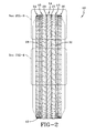
FIG. 2 is a front plan view thereof. -
FIG. 3 is an enlarged view of a portion of the tread taken fromFIG. 2 . -
FIG. 4 is an enlarged fragmented front view taken fromFIG. 2 . -
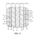
FIG. 5 is a barrel shaped foot print of the tire tread. - With reference to
FIGS. 1 through 5 , atire 10 is constructed having acircumferential tread 12 including acenter tread rib 14, a pair ofintermediate ribs center rib 14 and separated from the center rib by respectivecircumferential grooves shoulder tread regions shoulder groove shoulder regions narrow groove respective groove - A circumferential array of spaced apart
groove fingers tread 12 across arespective shoulder region lateral groove fingers 36 of theshoulder region 24 include generallystraight groove segments intersection 44. The circumferential array of spaced apartgroove fingers 38 of theopposite shoulder region 26 are likewise constructed having inclinedstraight groove segments intersection 50. Thegroove fingers intersections circumferential grooves - Each
shoulder region lateral sipes lateral sipes shoulder regions straight sipe segments intersections sipes intersections sipes circumferential grooves sipes inward end portion respective groove intermediate rib - It will be apparent from
FIGS. 1 through 5 that thelateral siping shoulder regions shoulder regions sipes - The
tread 12 provides a beneficial performance in a commercial vehicle, particularly in a truck steer tire. Thesipes ends circumferential grooves tread 12, five (shown) or six (not shown) circumferential ribs may be deployed. Each of thesipes intersection narrow grooves sipes 52 of theshoulder region 24 are angled and inclined in an opposite direction from thesipes 54 in theopposite shoulder region 26 and maintain a preferred constant depth of 2-3 mm along the entirety of the sipe length when the tire tread is new. Thesipes shoulder regions
Claims (15)
- A tire tread comprising a central region and first and second shoulder regions adjacent the central region, wherein at least one of the shoulder regions comprises a circumferential array of spaced apart shoulder sipes (52, 54), each of the shoulder sipes (52, 54) having a depth in an unworn tire tread condition within a depth range of from 1 mm to 3.5 mm, and wherein each shoulder sipe (52, 54) comprises at least one sipe segment having a longitudinal axis oriented in a substantially axial direction within a range of between +/- 20 degrees of the tire axial direction.
- The tire tread of claim 1, wherein the shoulder sipes (52, 54) reside exclusively within one of the shoulder regions of the tire tread (12).
- The tire tread of claim 1, wherein the shoulder sipes (52, 54) reside exclusively within both the first and the second shoulder regions of the tire tread (12).
- The tire tread of at least one of the previous claims, wherein the shoulder sipes (52, 54) each comprise a plurality of end-to-end straight sipe segments (56, 58, 62, 64).
- The tire tread of claim 4, wherein the number of straight sipe segments (56, 58, 62, 64) within each shoulder sipe (52, 54) is less than five, preferably two or three.
- The tire tread of at least one of the previous claims, wherein each shoulder sipe (52, 54) extends across a circumferential shoulder groove (32, 34) within a respective shoulder region, the circumferential shoulder groove (32, 34) preferably having an axial width of from 1 mm to 5 mm or from 2 to 4 mm.
- The tire tread of at least one of the previous claims, wherein the tire tread (12) comprises of five, six, seven or eight circumferential ribs, and wherein adjacent ribs are separated by a circumferential groove (44, 20, 22, 28, 30, 34).
- The tire tread of at least one of the previous claims, wherein each shoulder sipe (52, 54) has at least a first straight segment (58, 64) and a second straight segment (56, 62) intersecting at an end-to-end intersection (60, 66) with respect to each other at an intersection angle.
- The tire tread of claim 8, wherein the first straight segment (58, 64) and the second straight segment (60, 66) of each shoulder sipe (52, 54) incline in opposite directions from the end-to-end intersection (60, 66).
- The tire tread of claim 8 or 9, wherein the end-to-end intersection (60, 66) of each shoulder sipe (52, 54) is located at a circumferential shoulder groove (32, 34).
- The tire tread of at least one of the previous claims, wherein the shoulder sipes (52) of the first shoulder region are inclined in an opposite direction than the shoulder sipes (54) in the second shoulder region.
- The tire tread of at least one of the previous claims, wherein each of the shoulder sipes (52, 54) has a depth in an unworn tire tread condition within a depth range of from 2 mm to 3 mm.
- The tire tread of at least one of the previous claims, wherein each sipe segment of the shoulder sipes (52, 54) has a longitudinal axis oriented in a substantially axial direction within a range of between +/- 20 degrees, alternatively +/- 15 degrees or +/-10 degrees, of the tire axial direction.
- The tire tread of at least one of the previous claims, wherein one or both of the first and second shoulder regions comprise a circumferential array of spaced apart shoulder groove fingers (36, 38) wherein each shoulder groove finger (36, 38) has a longitudinal axis oriented in a substantially axial direction within a range of between +/- 20 degrees.
- A tire, preferably a truck tire, comprising a tread (12) in accordance with at least one of the previous claims.
Applications Claiming Priority (1)
| Application Number | Priority Date | Filing Date | Title |
|---|---|---|---|
| US13/116,350 US20120298269A1 (en) | 2011-05-26 | 2011-05-26 | Commercial truck tire |
Publications (2)
| Publication Number | Publication Date |
|---|---|
| EP2527165A2 true EP2527165A2 (en) | 2012-11-28 |
| EP2527165A3 EP2527165A3 (en) | 2013-03-13 |
Family
ID=46168188
Family Applications (1)
| Application Number | Title | Priority Date | Filing Date |
|---|---|---|---|
| EP12168876A Withdrawn EP2527165A3 (en) | 2011-05-26 | 2012-05-22 | Tire tread and truck tire |
Country Status (4)
| Country | Link |
|---|---|
| US (1) | US20120298269A1 (en) |
| EP (1) | EP2527165A3 (en) |
| CN (1) | CN102795059B (en) |
| BR (1) | BR102012012203A2 (en) |
Cited By (2)
| Publication number | Priority date | Publication date | Assignee | Title |
|---|---|---|---|---|
| WO2017093662A1 (en) * | 2015-12-03 | 2017-06-08 | Compagnie Generale Des Etablissements Michelin | Tire tread block geometry |
| CN112533770A (en) * | 2018-08-09 | 2021-03-19 | 米其林集团总公司 | Tire tread |
Families Citing this family (14)
| Publication number | Priority date | Publication date | Assignee | Title |
|---|---|---|---|---|
| JP6135070B2 (en) * | 2012-08-22 | 2017-05-31 | 横浜ゴム株式会社 | Pneumatic tire |
| DE112014003255B4 (en) | 2013-07-12 | 2022-07-28 | The Yokohama Rubber Co., Ltd. | tire |
| JP6420547B2 (en) * | 2014-01-27 | 2018-11-07 | 住友ゴム工業株式会社 | Pneumatic tire |
| JP6329011B2 (en) * | 2014-06-16 | 2018-05-23 | 株式会社ブリヂストン | Pneumatic tire |
| WO2016027647A1 (en) * | 2014-08-19 | 2016-02-25 | 横浜ゴム株式会社 | Pneumatic tire |
| JP6231974B2 (en) * | 2014-11-27 | 2017-11-15 | 住友ゴム工業株式会社 | Pneumatic tire |
| JP6366525B2 (en) * | 2015-02-27 | 2018-08-01 | 東洋ゴム工業株式会社 | Pneumatic tire |
| USD807810S1 (en) * | 2015-04-30 | 2018-01-16 | Hongling Zhao | Tire |
| USD794542S1 (en) * | 2015-09-03 | 2017-08-15 | The Goodyear Tire & Rubber Company | Tire |
| JP6828387B2 (en) * | 2016-11-14 | 2021-02-10 | 住友ゴム工業株式会社 | tire |
| JP6822095B2 (en) * | 2016-11-24 | 2021-01-27 | 住友ゴム工業株式会社 | tire |
| CN110978894A (en) * | 2019-12-19 | 2020-04-10 | 安徽佳通乘用子午线轮胎有限公司 | Wear-resisting pure electric operation type tire of making an uproar that falls |
| USD944719S1 (en) * | 2020-03-13 | 2022-03-01 | Sichuan Tyre & Rubber Co., Ltd. | Tire |
| USD924786S1 (en) * | 2020-04-30 | 2021-07-13 | The Yokohama Rubber Co., Ltd. | Automobile tire |
Citations (1)
| Publication number | Priority date | Publication date | Assignee | Title |
|---|---|---|---|---|
| US5804000A (en) * | 1995-10-17 | 1998-09-08 | The Yokohama Rubber Co., Ltd. | Pneumatic radial tire including main grooves and sub-grooves |
Family Cites Families (10)
| Publication number | Priority date | Publication date | Assignee | Title |
|---|---|---|---|---|
| USD409532S (en) * | 1997-07-01 | 1999-05-11 | The Goodyear Tire & Rubber Company | Tire tread |
| US6439284B1 (en) * | 1997-10-03 | 2002-08-27 | The Goodyear Tire & Rubber Company | Tread for a pneumatic tire including aquachannel |
| DE19827244A1 (en) * | 1998-06-18 | 1999-12-23 | Dunlop Gmbh | Vehicle tire with different tread profile for various driving conditions and method for designing the tread to suit different driving characteristics |
| USD421943S (en) * | 1999-05-05 | 2000-03-28 | The Goodyear Tire & Rubber Company | Tire tread |
| CN2396988Y (en) * | 1999-11-16 | 2000-09-20 | 上海轮胎橡胶(集团)股份有限公司轮胎研究所 | Tyre with patterns |
| USD445731S1 (en) * | 2000-07-21 | 2001-07-31 | Bridgestone/Firestone Research, Inc. | Tire tread |
| USD444431S1 (en) * | 2000-08-29 | 2001-07-03 | The Goodyear Tire & Rubber Company | Tire tread |
| JP3963769B2 (en) * | 2002-04-30 | 2007-08-22 | 横浜ゴム株式会社 | Pneumatic tire |
| JP4954743B2 (en) * | 2007-02-08 | 2012-06-20 | 東洋ゴム工業株式会社 | Pneumatic tire |
| DE102008037563A1 (en) * | 2008-11-19 | 2010-05-20 | Continental Reifen Deutschland Gmbh | Pneumatic tire for passenger car, has narrower sections of preset widths arranged alternatively between broader sections of preset widths, where broader sections are adjacent to narrower sections |
-
2011
- 2011-05-26 US US13/116,350 patent/US20120298269A1/en not_active Abandoned
-
2012
- 2012-05-22 BR BR102012012203-0A patent/BR102012012203A2/en not_active IP Right Cessation
- 2012-05-22 EP EP12168876A patent/EP2527165A3/en not_active Withdrawn
- 2012-05-25 CN CN201210165469.1A patent/CN102795059B/en not_active Expired - Fee Related
Patent Citations (1)
| Publication number | Priority date | Publication date | Assignee | Title |
|---|---|---|---|---|
| US5804000A (en) * | 1995-10-17 | 1998-09-08 | The Yokohama Rubber Co., Ltd. | Pneumatic radial tire including main grooves and sub-grooves |
Cited By (4)
| Publication number | Priority date | Publication date | Assignee | Title |
|---|---|---|---|---|
| WO2017093662A1 (en) * | 2015-12-03 | 2017-06-08 | Compagnie Generale Des Etablissements Michelin | Tire tread block geometry |
| FR3044595A1 (en) * | 2015-12-03 | 2017-06-09 | Michelin & Cie | GEOMETRY OF BLOCKS OF A TIRE TREAD FOR TIRES. |
| CN112533770A (en) * | 2018-08-09 | 2021-03-19 | 米其林集团总公司 | Tire tread |
| CN112533770B (en) * | 2018-08-09 | 2022-09-23 | 米其林集团总公司 | Tire tread |
Also Published As
| Publication number | Publication date |
|---|---|
| EP2527165A3 (en) | 2013-03-13 |
| CN102795059A (en) | 2012-11-28 |
| CN102795059B (en) | 2016-05-11 |
| BR102012012203A2 (en) | 2014-12-02 |
| US20120298269A1 (en) | 2012-11-29 |
Similar Documents
| Publication | Publication Date | Title |
|---|---|---|
| US20120298269A1 (en) | Commercial truck tire | |
| CN107031303B (en) | Pneumatic tire | |
| JP4957786B2 (en) | Pneumatic tire | |
| RU2469872C1 (en) | Pneumatic tire | |
| US8863797B2 (en) | Winter tire tread siping pattern | |
| JP6724379B2 (en) | Pneumatic tire | |
| US9751365B2 (en) | High mileage truck tire tread | |
| CN102774242B (en) | Pneumatic tire | |
| US20120103493A1 (en) | Winter tire center tread pattern | |
| EP2447091B1 (en) | Tread for a vehicle tire | |
| EP3078505B1 (en) | Tire for winter | |
| JP2017190123A (en) | Pneumatic tire | |
| CN104723799B (en) | Pneumatic tire | |
| CN107972414A (en) | Tire | |
| CN101370674A (en) | pneumatic tire | |
| JPH10230712A (en) | Pneumatic radial tires for all season passenger cars | |
| JP7024512B2 (en) | tire | |
| CN103442909A (en) | Pneumatic tire | |
| JP3145762B2 (en) | Pneumatic tire | |
| JP2008030605A (en) | Pneumatic tire | |
| CN108290461B (en) | Vehicle Pneumatic Tires | |
| JP2004026158A (en) | Studless pneumatic tire for heavy load | |
| EP2265450B1 (en) | Heavy- load vehicle tire | |
| JPH03186407A (en) | Pneumatic tire | |
| CA2084741C (en) | Block pattern tire with optimized groove depth ratios, sipe depth and length ratios |
Legal Events
| Date | Code | Title | Description |
|---|---|---|---|
| PUAI | Public reference made under article 153(3) epc to a published international application that has entered the european phase |
Free format text: ORIGINAL CODE: 0009012 |
|
| AK | Designated contracting states |
Kind code of ref document: A2 Designated state(s): AL AT BE BG CH CY CZ DE DK EE ES FI FR GB GR HR HU IE IS IT LI LT LU LV MC MK MT NL NO PL PT RO RS SE SI SK SM TR |
|
| AX | Request for extension of the european patent |
Extension state: BA ME |
|
| PUAL | Search report despatched |
Free format text: ORIGINAL CODE: 0009013 |
|
| AK | Designated contracting states |
Kind code of ref document: A3 Designated state(s): AL AT BE BG CH CY CZ DE DK EE ES FI FR GB GR HR HU IE IS IT LI LT LU LV MC MK MT NL NO PL PT RO RS SE SI SK SM TR |
|
| AX | Request for extension of the european patent |
Extension state: BA ME |
|
| RIC1 | Information provided on ipc code assigned before grant |
Ipc: B60C 11/12 20060101AFI20130204BHEP |
|
| 17P | Request for examination filed |
Effective date: 20130913 |
|
| RBV | Designated contracting states (corrected) |
Designated state(s): AL AT BE BG CH CY CZ DE DK EE ES FI FR GB GR HR HU IE IS IT LI LT LU LV MC MK MT NL NO PL PT RO RS SE SI SK SM TR |
|
| 17Q | First examination report despatched |
Effective date: 20140219 |
|
| RIC1 | Information provided on ipc code assigned before grant |
Ipc: B60C 11/12 20060101AFI20170630BHEP Ipc: B60C 11/03 20060101ALI20170630BHEP |
|
| STAA | Information on the status of an ep patent application or granted ep patent |
Free format text: STATUS: THE APPLICATION IS DEEMED TO BE WITHDRAWN |
|
| 18D | Application deemed to be withdrawn |
Effective date: 20180302 |