EP2527162A1 - Carcass ply structure for a pneumatic tire - Google Patents
Carcass ply structure for a pneumatic tire Download PDFInfo
- Publication number
- EP2527162A1 EP2527162A1 EP12168866A EP12168866A EP2527162A1 EP 2527162 A1 EP2527162 A1 EP 2527162A1 EP 12168866 A EP12168866 A EP 12168866A EP 12168866 A EP12168866 A EP 12168866A EP 2527162 A1 EP2527162 A1 EP 2527162A1
- Authority
- EP
- European Patent Office
- Prior art keywords
- carcass ply
- tire
- cord
- bead core
- pneumatic tire
- Prior art date
- Legal status (The legal status is an assumption and is not a legal conclusion. Google has not performed a legal analysis and makes no representation as to the accuracy of the status listed.)
- Granted
Links
Images
Classifications
-
- B—PERFORMING OPERATIONS; TRANSPORTING
- B60—VEHICLES IN GENERAL
- B60C—VEHICLE TYRES; TYRE INFLATION; TYRE CHANGING; CONNECTING VALVES TO INFLATABLE ELASTIC BODIES IN GENERAL; DEVICES OR ARRANGEMENTS RELATED TO TYRES
- B60C9/00—Reinforcements or ply arrangement of pneumatic tyres
- B60C9/02—Carcasses
- B60C9/04—Carcasses the reinforcing cords of each carcass ply arranged in a substantially parallel relationship
- B60C9/08—Carcasses the reinforcing cords of each carcass ply arranged in a substantially parallel relationship the cords extend transversely from bead to bead, i.e. radial ply
-
- B—PERFORMING OPERATIONS; TRANSPORTING
- B60—VEHICLES IN GENERAL
- B60C—VEHICLE TYRES; TYRE INFLATION; TYRE CHANGING; CONNECTING VALVES TO INFLATABLE ELASTIC BODIES IN GENERAL; DEVICES OR ARRANGEMENTS RELATED TO TYRES
- B60C15/00—Tyre beads, e.g. ply turn-up or overlap
- B60C15/04—Bead cores
Definitions
- the present invention relates to a pneumatic tire having a carcass reinforced with a dual carcass structure.
- a conventional pneumatic tire comprises a carcass ply having a main portion that extends between both bead cores of the tire and turnup portions that are anchored around each bead core.
- the conventional tire has radially outer edges of the turnup portions of the carcass ply disposed radially outwardly of the bead cores a minimal distance and are in contact with the main portion of the carcass ply.
- Suitable elastomeric materials surround the bead core, carcass ply, and other elastomeric components to complete the bead portion of the tire.
- a clamping member comprise a strip of side-by-side cords of a heat shrinkable material embedded in a suitable elastomeric substance having a permanent thermal shrinkage of at least 2 percent.
- This strip of cords extends from a location radially and axially inward of the bead core to a location radially outward of the bead core and there is no filler strip or apex disposed between the main portion and turnup portion of the carcass ply.
- the heat shrinkable material may be 1260/2 Nylon 6,6, having a permanent thermal shrinkage of about 4 percent. It is a continual goal in the tire art to simplify the construction and reduce the expense of building tires, yet improve the durability, handling, rolling resistance, and other properties of tires.
- Another conventional pneumatic tire may have two carcass plies or a single carcass ply reinforced with metallic cords, respectively.
- Either conventional tire may have a high ending ply turnup and locked bead construction.
- Still another pneumatic tire may have a single carcass ply reinforced with parallel metallic cords, each cord composed of at least one filament having a tensile strength of at least (-2000 x D+4400 MPa) x 95%, where D is a filament diameter in millimeters.
- the turnup portion of the single carcass ply in the bead portion of the conventional pneumatic tire may be interposed between the bead core and a toe guard, with the radially outer edge of each turnup portion being in contact with the main portion of the carcass ply and extending to an end point 0.5 to 4.0 inches (12.7 to 101.6 mm) radially outward of the bead core.
- the toe guard may have a first end and a second end, each end disposed directly adjacent to the carcass ply.
- the first end of the toe guard may be located on the axially inner side of the main portion of the carcass ply at a location 0.4 to 3.5 inches (10 to 89 mm) radially outward of the bead core and the second end may be located at a point ranging from substantially the axially outermost point of the bead core to a location 3.5 inches (89 mm) radially outward of the bead core.
- the first end and second end of the toe guard may be a shorter distance from the bead core than the end point of the turnup portion of the carcass ply.
- the toe guard may be a rubber material, a flexible textile material, or a heat shrinkable material.
- the toeguard may comprise a strip of side-by-side cords of a non-metallic heat shrinkable material which has a permanent thermal shrinkage of at least 2 percent wrapped circumferentially about the bead core and carcass ply turnup a plurality of times.
- the toeguard is a rubber material, it may be canlendered gum strips circumferentially wound around the bead core and carcass ply turnups a plurality of times.
- the invention relates to a tire in accordance with claim 1.
- a pneumatic tire in accordance with a preferred embodiment of the present invention includes a pair of axially spaced apart annular bead cores, a first carcass ply, and a second carcass ply.
- the first carcass ply is wrapped around each bead core and has a first pair of carcass ply turnups substantially contiguous with the first carcass ply from the bead core to radially outer ends of the first pair of carcass ply turnups.
- the first carcass ply has a first polyester cord with a construction of 1400-1600 denier/2 with 8-10/8-10 turns per 2.54 cm (tpi).
- the second carcass ply is radially adjacent to and radially outward of the first carcass ply.
- the second carcass ply is wrapped around each bead core and has a second pair of carcass ply turnups substantially contiguous with the second carcass ply from the bead core to radially outer ends of the second pair of carcass ply turnups.
- the second carcass ply has a second polyester cord with a construction of 900-1100 denier/2 with 11-13/11-13 tpi.
- the first carcass ply comprises 14-20 ends per 2.54 cm (epi) of the first polyester cord.
- the second carcass ply comprises 14-20 epi of the second polyester cord.
- the pneumatic tire may further include a toeguard associated with each bead core.
- the pneumatic tire may further include an apex portion adjacent each carcass ply turnup along an axially outer side of each carcass ply turnup.
- the bead cores may have a radial cross-sectional shape which is selected from the group consisting of a pentagon, a hexagon, a rectangle, and a circle.
- Apex means an elastomeric filler located radially above the bead core and between the plies and the turnup ply.
- Dtex means the weight in grams per 9000 meters (unit for expressing linear density). Dtex means the weight in grams per 10,000 meters.
- Density means weight per unit length.
- “Lateral” means an axial direction.
- Ply means a cord-reinforced layer of rubber-coated radially deployed or otherwise parallel cords.
- Ring and radially are used to mean directions radially toward or away from the axis of rotation of the tire.
- Toe guard refers to the circumferentially deployed elastomeric rim-contacting portion of the tire axially inward of each bead.
- “Turnup end” means the portion of a carcass ply that turns upward (i.e., radially outward) from the beads about which the ply is wrapped.
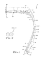
- FIG. 1 shows a cross-sectional view of an example tire 10 in accordance with the present invention.
- the example tire 10 may have a pair of bead cores 11, each comprising a plurality of metallic filaments.
- the example tire 10 may be characterized by a first carcass ply 14 and a second carcass ply 12 that extend between the bead cores 11 and turnup portions 12a, 14a anchored around each bead core 11.
- a belt structure 20 may have at least two belts 23, 24 disposed radially outward of the main portion of the carcass plies 12, 14 and a ground engaging tread portion 15 may be disposed radially outward of the belt structure 20.
- Sidewall portions 16 may extend radially inward from the tread portion 15 to the bead cores 11.
- an innerliner 17 may be used on the axially inner side of the carcass ply 14.
- the innerliner 17 may consist of a layer or layers of elastomer or other material that form an inside surface of the tire 10 for containing inflation fluid, such as air, within the tire. Additional barriers, reinforcement strips, and/or gum strips (not shown) may be disposed at suitable locations between the innerliner 17 and the main portion of the carcass ply 14 to avoid penetration of rubber through the carcass ply 14 during curing.
- the belt structure 20 preferably comprises a plurality of belt plies 23, 24 located radially outward of the carcass plies 12, 14 in a crown portion of the tire 10.
- the elastomeric tread portion 15 may be disposed radially outward of the belt structure 20.
- the belt structure 20 may have at least two annular layers or plies 23, 24 of parallel cords, woven or unwoven, underlying the tread portion 15, unanchored to the bead cores 11.
- the belt structure 20 preferably has both left and right cord angles in the range from 40 to 15 degrees with respect to an equatorial plane EP of the tire 10.
- the belt structure 20 illustrated in FIG. 1 and described herein is shown as an example.
- cords in the belt plies 23, 24 may be rayon, polyester, glass fiber, aramid, steel wire, and/or the like.
- the cords may be steel wire filaments having a tensile strength of at least (-1400 x D + 4050) x 95% when D is the filament diameter in millimeters.
- the cords may be composed of at least one filament having a tensile strength of at least (-2000 x D + 4050) x 95% when D is as defined above.
- the bead cores 11 preferably each comprise a plurality of wraps of a single metallic filament 9.
- Each of the bead cores 11 have a circumferential cross-sectional shape, which may be substantially triangular, pentagonal, hexagonal, rectangular, or circular.
- the metallic filament 9 used in the bead cores 11 may be, for example, a 0.05 inch (1.27 mm) diameter steel wire coated with bronze to enhance its bonding with rubber. Other filament diameters may also be used.
- the cords of the carcass plies 12, 14 preferably intersect the equatorial plane (EP) of the tire 10 at an angle in the range from 75 to 105 degrees. Further, the cords may intersect at an angle of 82 to 98 degrees or 89 to 91 degrees.
- each turnup portion 12a, 14a is in contact with the main portion of the carcass plies 12, 14 and preferably extends to an end point 12B, 14B 0.5 inches (12.7 mm) to 4.0 inches (101.6 mm) radially outward of each bead core 11 from the middle of each bead core.
- the turnup portions 12A, 14A may extend to an end point 12B, 14B 0.5 inches (12.7 mm) to 3.5 inches (88.9 mm) radially outward of each bead core 11.
- End point 12B may be radially inward (not shown) or radially outward ( FIG. 1 ) of end point 14B. Locking in of the bead cores 11 may be achieved by adhesion between the turnup portions 12a, 14a and the main portion of the carcass plies 12, 14.
- Each toe guard 18 has a first-end 18A and a second end 18B.
- each end 18A, 18B is disposed directly adjacent to the carcass ply 14.
- the first end 18A is located on the axially inner side of the main portion of the carcass ply 14 at a location 0.4 inches (10 mm) to 3.5 inches (89 mm) radially outward of the bead core 11 from substantially the middle of the bead core.
- the first end 18A may be located on the axially inner side of the main portion of the carcass ply 14 at a location A 0.4 inches (10.16 mm) to 2.0 inches (50.8 mm) radially outward of the bead core 11.
- the second end 18B of the toe guard 18 is located at a point B ranging from the axially outermost point of the bead core 11 to a location 3.5 inches (89 mm) radially outward of the bead core from the middle of the bead core.
- the second end 18B of the toe guard 18 may be located at a point B ranging from the axially outermost point of the bead core 11 to a location B 2.0 inches (50.8 mm) radially outward of the bead core 11.
- the carcass ply turnups 12a, 14a may be folded about the bead core 11 and locked against the main portion of the carcass ply 12 by the sidewall 16.
- the wrap-around toeguard 18 may be made of a single elastomeric material or composition 28.
- conventional passenger/SUV tires may have a casing/carcass construction that uses two layers of "ply treatment” (e.g., fabric cords embedded in a rubber matrix).
- Conventional tires typically use the same denier (cord weight) of a specific type of polyester cord for both layers.
- a conventional tire may use polyester cord with a denier of 1500 in both ply layers.
- one example ply 12 or 14 use higher denier polyester cords 100 (e.g., 1500, 2000) and the other example ply 14 or 12 may use lower denier polyester cords 110 (e.g., 1000, 1500).
- the benefits of such a two ply construction may include a reduction in tire weight, a reduction in tire/material cost, a reduction in rolling resistance force, improved tuning of noise-vibration-handling (NVH) performance characteristics, and lower heat generation in the casing structure leading to improved durability and high-speed performance characteristics.
- NDH noise-vibration-handling
- either ply 12, 14 may have a cord 100, 110 with a construction of 900-2500 denier/2 polyester with 7-15/7-15 turns per inch (tpi) and 14-35 or 20-35 end per 2.54 cm (epi).
- the radially outer carcass ply 12 may have a cord 100 with a construction of 900-1100 denier/2 polyester with 11-13/11-13 tpi and 14-20 epi; and the radially inner carcass ply 14 may have a cord 110 with a construction of 1400-1600 denier/2 polyester with 8-10/8-10 tpi and 14-20 epi.
- a carcass ply structure 12, 14 in accordance with the present invention produces excellent cost, weight, and performance characteristics in a pneumatic tire 10.
- This structure 12, 14 thus enhances the performance of the tire pneumatic 10, even though the complexities of the structure and behavior of the pneumatic tire are such that no complete and satisfactory theory has been propounded.
Landscapes
- Engineering & Computer Science (AREA)
- Mechanical Engineering (AREA)
- Tires In General (AREA)
Abstract
Description
- The present invention relates to a pneumatic tire having a carcass reinforced with a dual carcass structure.
- A conventional pneumatic tire comprises a carcass ply having a main portion that extends between both bead cores of the tire and turnup portions that are anchored around each bead core. The conventional tire has radially outer edges of the turnup portions of the carcass ply disposed radially outwardly of the bead cores a minimal distance and are in contact with the main portion of the carcass ply. Suitable elastomeric materials surround the bead core, carcass ply, and other elastomeric components to complete the bead portion of the tire. A clamping member comprise a strip of side-by-side cords of a heat shrinkable material embedded in a suitable elastomeric substance having a permanent thermal shrinkage of at least 2 percent. This strip of cords extends from a location radially and axially inward of the bead core to a location radially outward of the bead core and there is no filler strip or apex disposed between the main portion and turnup portion of the carcass ply. The heat shrinkable material may be 1260/2 Nylon 6,6, having a permanent thermal shrinkage of about 4 percent. It is a continual goal in the tire art to simplify the construction and reduce the expense of building tires, yet improve the durability, handling, rolling resistance, and other properties of tires.
- Another conventional pneumatic tire may have two carcass plies or a single carcass ply reinforced with metallic cords, respectively. Either conventional tire may have a high ending ply turnup and locked bead construction.
- Still another pneumatic tire may have a single carcass ply reinforced with parallel metallic cords, each cord composed of at least one filament having a tensile strength of at least (-2000 x D+4400 MPa) x 95%, where D is a filament diameter in millimeters. The turnup portion of the single carcass ply in the bead portion of the conventional pneumatic tire may be interposed between the bead core and a toe guard, with the radially outer edge of each turnup portion being in contact with the main portion of the carcass ply and extending to an end point 0.5 to 4.0 inches (12.7 to 101.6 mm) radially outward of the bead core. The toe guard may have a first end and a second end, each end disposed directly adjacent to the carcass ply.
- The first end of the toe guard may be located on the axially inner side of the main portion of the carcass ply at a location 0.4 to 3.5 inches (10 to 89 mm) radially outward of the bead core and the second end may be located at a point ranging from substantially the axially outermost point of the bead core to a location 3.5 inches (89 mm) radially outward of the bead core. The first end and second end of the toe guard may be a shorter distance from the bead core than the end point of the turnup portion of the carcass ply.
- The toe guard may be a rubber material, a flexible textile material, or a heat shrinkable material. For example, the toeguard may comprise a strip of side-by-side cords of a non-metallic heat shrinkable material which has a permanent thermal shrinkage of at least 2 percent wrapped circumferentially about the bead core and carcass ply turnup a plurality of times. When the toeguard is a rubber material, it may be canlendered gum strips circumferentially wound around the bead core and carcass ply turnups a plurality of times.
- The use of separate stiffeners or apexes and chafer strips were shown to be used in combination with the plurality of windings of the gum strip used in the toeguard to form the bead portion of the tire. The uses of multiple windings of strip of material wound around the green or uncured tire to form a carcass in cylindrical form may lead to variations in the rubber thicknesses and gauges around the circumference of the tire as it is shaped toroidally and placed in a mold to cure under temperature and pressure.
- The invention relates to a tire in accordance with claim 1.
- Dependent claims refer to preferred embodiments of the invention.
- A pneumatic tire in accordance with a preferred embodiment of the present invention includes a pair of axially spaced apart annular bead cores, a first carcass ply, and a second carcass ply. The first carcass ply is wrapped around each bead core and has a first pair of carcass ply turnups substantially contiguous with the first carcass ply from the bead core to radially outer ends of the first pair of carcass ply turnups. The first carcass ply has a first polyester cord with a construction of 1400-1600 denier/2 with 8-10/8-10 turns per 2.54 cm (tpi). The second carcass ply is radially adjacent to and radially outward of the first carcass ply. The second carcass ply is wrapped around each bead core and has a second pair of carcass ply turnups substantially contiguous with the second carcass ply from the bead core to radially outer ends of the second pair of carcass ply turnups. The second carcass ply has a second polyester cord with a construction of 900-1100 denier/2 with 11-13/11-13 tpi.
- According to another preferred aspect of the present invention, the first carcass ply comprises 14-20 ends per 2.54 cm (epi) of the first polyester cord.
- According to still another preferred aspect of the present invention, the second carcass ply comprises 14-20 epi of the second polyester cord.
- According to yet another aspect of the present invention, the pneumatic tire may further include a toeguard associated with each bead core.
- According to still another aspect of the present invention, the pneumatic tire may further include an apex portion adjacent each carcass ply turnup along an axially outer side of each carcass ply turnup.
- According to yet another aspect of the present invention, the bead cores may have a radial cross-sectional shape which is selected from the group consisting of a pentagon, a hexagon, a rectangle, and a circle.
- The following definitions are controlling for the disclosed invention.
- "Apex" means an elastomeric filler located radially above the bead core and between the plies and the turnup ply.
- "Axial" and "axially" are used herein to refer to lines or directions that are parallel to the axis of rotation of the tire.
- "Denier" means the weight in grams per 9000 meters (unit for expressing linear density). Dtex means the weight in grams per 10,000 meters.
- "Density" means weight per unit length.
- "Lateral" means an axial direction.
- "Ply" means a cord-reinforced layer of rubber-coated radially deployed or otherwise parallel cords.
- "Radial" and "radially" are used to mean directions radially toward or away from the axis of rotation of the tire.
- "Toe guard" refers to the circumferentially deployed elastomeric rim-contacting portion of the tire axially inward of each bead.
- "Turnup end" means the portion of a carcass ply that turns upward (i.e., radially outward) from the beads about which the ply is wrapped.
- The invention will be described by way of example and with reference to the accompanying drawings in which:
-
FIG. 1 is one half of a schematic cross-sectional view of an example tire in accordance with the present invention. -
FIG. 2 is a schematic cross-sectional view of an example cord construction in accordance with the present invention. -
FIG. 1 shows a cross-sectional view of anexample tire 10 in accordance with the present invention. Theexample tire 10 may have a pair ofbead cores 11, each comprising a plurality of metallic filaments. Theexample tire 10 may be characterized by afirst carcass ply 14 and asecond carcass ply 12 that extend between thebead cores 11 and turnup portions 12a, 14a anchored around eachbead core 11. Abelt structure 20 may have at least twobelts carcass plies tread portion 15 may be disposed radially outward of thebelt structure 20.Sidewall portions 16 may extend radially inward from thetread portion 15 to thebead cores 11. On the axially inner side of thecarcass ply 14, aninnerliner 17 may be used. Theinnerliner 17 may consist of a layer or layers of elastomer or other material that form an inside surface of thetire 10 for containing inflation fluid, such as air, within the tire. Additional barriers, reinforcement strips, and/or gum strips (not shown) may be disposed at suitable locations between theinnerliner 17 and the main portion of thecarcass ply 14 to avoid penetration of rubber through thecarcass ply 14 during curing. - The
belt structure 20 preferably comprises a plurality ofbelt plies carcass plies tire 10. Theelastomeric tread portion 15 may be disposed radially outward of thebelt structure 20. Thebelt structure 20 may have at least two annular layers orplies tread portion 15, unanchored to thebead cores 11. Thebelt structure 20 preferably has both left and right cord angles in the range from 40 to 15 degrees with respect to an equatorial plane EP of thetire 10. Thebelt structure 20 illustrated inFIG. 1 and described herein is shown as an example. For example, in those instances where a larger tire is being constructed for use in a radial light truck application, three or more belts may be used. In addition, cords in the belt plies 23, 24 may be rayon, polyester, glass fiber, aramid, steel wire, and/or the like. The cords may be steel wire filaments having a tensile strength of at least (-1400 x D + 4050) x 95% when D is the filament diameter in millimeters. Further, the cords may be composed of at least one filament having a tensile strength of at least (-2000 x D + 4050) x 95% when D is as defined above. - The
bead cores 11 preferably each comprise a plurality of wraps of a singlemetallic filament 9. Each of thebead cores 11 have a circumferential cross-sectional shape, which may be substantially triangular, pentagonal, hexagonal, rectangular, or circular. Themetallic filament 9 used in thebead cores 11 may be, for example, a 0.05 inch (1.27 mm) diameter steel wire coated with bronze to enhance its bonding with rubber. Other filament diameters may also be used. - The cords of the carcass plies 12, 14 preferably intersect the equatorial plane (EP) of the
tire 10 at an angle in the range from 75 to 105 degrees. Further, the cords may intersect at an angle of 82 to 98 degrees or 89 to 91 degrees. - Preferably, the carcass plies 12, 14 and a
toe guard 18 are folded about eachbead core 11. Preferably, the radially outer edge of each turnup portion 12a, 14a is in contact with the main portion of the carcass plies 12, 14 and preferably extends to anend point bead core 11 from the middle of each bead core. Preferably, theturnup portions end point bead core 11.End point 12B may be radially inward (not shown) or radially outward (FIG. 1 ) ofend point 14B. Locking in of thebead cores 11 may be achieved by adhesion between the turnup portions 12a, 14a and the main portion of the carcass plies 12, 14. - Each
toe guard 18 has a first-end 18A and asecond end 18B. Preferably, eachend carcass ply 14. Preferably, thefirst end 18A is located on the axially inner side of the main portion of the carcass ply 14 at a location 0.4 inches (10 mm) to 3.5 inches (89 mm) radially outward of thebead core 11 from substantially the middle of the bead core. Further, thefirst end 18A may be located on the axially inner side of the main portion of the carcass ply 14 at a location A 0.4 inches (10.16 mm) to 2.0 inches (50.8 mm) radially outward of thebead core 11. Preferably, thesecond end 18B of thetoe guard 18 is located at a point B ranging from the axially outermost point of thebead core 11 to a location 3.5 inches (89 mm) radially outward of the bead core from the middle of the bead core. Further, thesecond end 18B of thetoe guard 18 may be located at a point B ranging from the axially outermost point of thebead core 11 to a location B 2.0 inches (50.8 mm) radially outward of thebead core 11. - In one embodiment, the carcass ply turnups 12a, 14a may be folded about the
bead core 11 and locked against the main portion of the carcass ply 12 by thesidewall 16. The wrap-aroundtoeguard 18 may be made of a single elastomeric material orcomposition 28. - As described above, conventional passenger/SUV tires may have a casing/carcass construction that uses two layers of "ply treatment" (e.g., fabric cords embedded in a rubber matrix). Conventional tires typically use the same denier (cord weight) of a specific type of polyester cord for both layers. For example, a conventional tire may use polyester cord with a denier of 1500 in both ply layers.
- In accordance with the present invention, one example ply 12 or 14 use higher denier polyester cords 100 (e.g., 1500, 2000) and the other example ply 14 or 12 may use lower denier polyester cords 110 (e.g., 1000, 1500). The benefits of such a two ply construction may include a reduction in tire weight, a reduction in tire/material cost, a reduction in rolling resistance force, improved tuning of noise-vibration-handling (NVH) performance characteristics, and lower heat generation in the casing structure leading to improved durability and high-speed performance characteristics.
- In general (
FIG. 2 ), either ply 12, 14 may have a cord 100, 110 with a construction of 900-2500 denier/2 polyester with 7-15/7-15 turns per inch (tpi) and 14-35 or 20-35 end per 2.54 cm (epi). Specifically, the radially outer carcass ply 12 may have a cord 100 with a construction of 900-1100 denier/2 polyester with 11-13/11-13 tpi and 14-20 epi; and the radially inner carcass ply 14 may have a cord 110 with a construction of 1400-1600 denier/2 polyester with 8-10/8-10 tpi and 14-20 epi. - As stated above, a
carcass ply structure pneumatic tire 10. Thisstructure tire pneumatic 10, even though the complexities of the structure and behavior of the pneumatic tire are such that no complete and satisfactory theory has been propounded.
Claims (14)
- A pneumatic tire comprising a pair of axially spaced apart annular bead cores (11); a first carcass ply (14) wrapped around each bead core (11) and having a first pair of carcass ply turnup portions (14A) substantially contiguous with the first carcass ply (14) from the bead core (11) to radially outer ends (14B) of the first pair of carcass ply turnup portion (14A), the first carcass ply (14) comprising a first non-metallic cord (110) with a construction of 1300-2500 denier/2 with 7-15/7-15 turns per 2.54 cm (tpi); and a second carcass ply (12) radially adjacent to the first carcass ply (14), the second carcass (12) ply being wrapped around each bead core (11) and having a second pair of carcass ply turnup portions (12A) substantially contiguous with the second carcass ply (12) from the bead core (11) to radially outer ends (12B) of the second pair of carcass ply turnup portions, the second carcass ply (12) comprising a second non-metallic cord (100) with a construction of 900-1200 denier/2 with 9-15/9-15 turns per 2.54 cm (tpi).
- The tire of claim 1 wherein the first non-metallic cord (110) has a construction of 1400-1600 denier/2 with 8-10/8-10 turns per 2.54 cm (tpi).
- The tire of claim 1 or 2 wherein the second non-metallic cord (100) has a construction of 900-1100 denier/2 with 11-13/11-13 turns per 2.54 cm (tpi).
- The tire of claim 1, 2 or 3 wherein the second carcass ply (12) is radially outward of the first carcass ply (14).
- The tire of claim 1, 2 or 3 wherein the second carcass ply (12) is radially inward of the first carcass ply (14).
- The tire of at least one of the previous claims wherein the first non-metallic cord is a polyester cord.
- The tire of at least one of the previous claims wherein the second non-metallic cord is a polyester cord.
- The pneumatic tire of at least one of the previous claims wherein the first carcass ply (14) comprises 14 to 35 ends per 2.54 cm (epi) of the first cord (110).
- The pneumatic tire of at least one of the previous claims wherein the second carcass ply (12) comprises 14 to 35 ends per 2.54 cm (epi) of the second cord (110).
- The pneumatic tire of at least one of the previous claims wherein the first carcass ply (14) comprises 14 to 20 ends per 2.54 cm (epi) of the first cord (110).
- The pneumatic tire of at least one of the previous claims wherein the second carcass ply (12) comprises 14 to 20 ends per 2.54 cm (epi) of the second cord (110).
- The pneumatic tire of at least one of the previous claims further comprising a wrap-around toeguard (18) associated with each bead core (11).
- The pneumatic tire of at least one of the previous claims further comprising an apex portion.
- The pneumatic tire of at least one of the previous claims wherein the bead cores (11) have a radial cross-sectional shape which is selected from the group consisting of a pentagon, a hexagon, a rectangle, and a circle.
Applications Claiming Priority (1)
| Application Number | Priority Date | Filing Date | Title |
|---|---|---|---|
| US13/115,157 US20120298278A1 (en) | 2011-05-25 | 2011-05-25 | Carcass ply structure for a pneumatic tire |
Publications (2)
| Publication Number | Publication Date |
|---|---|
| EP2527162A1 true EP2527162A1 (en) | 2012-11-28 |
| EP2527162B1 EP2527162B1 (en) | 2014-09-03 |
Family
ID=46168184
Family Applications (1)
| Application Number | Title | Priority Date | Filing Date |
|---|---|---|---|
| EP12168866.7A Not-in-force EP2527162B1 (en) | 2011-05-25 | 2012-05-22 | Carcass ply structure for a pneumatic tire |
Country Status (2)
| Country | Link |
|---|---|
| US (1) | US20120298278A1 (en) |
| EP (1) | EP2527162B1 (en) |
Families Citing this family (6)
| Publication number | Priority date | Publication date | Assignee | Title |
|---|---|---|---|---|
| FR2990897B1 (en) * | 2012-05-24 | 2014-05-09 | Michelin & Cie | PNEUMATIC FOLDABLE, METHOD, USE |
| DE112014003404T5 (en) * | 2013-07-24 | 2016-05-25 | The Yokohama Rubber Co., Ltd. | tire |
| DE102014222306A1 (en) * | 2014-10-31 | 2016-06-09 | Continental Reifen Deutschland Gmbh | Pneumatic vehicle tire having a carcass |
| JP6645182B2 (en) * | 2015-12-25 | 2020-02-14 | 横浜ゴム株式会社 | Pneumatic tire |
| CN110194028B (en) * | 2019-06-26 | 2023-06-06 | 青岛双星轮胎工业有限公司 | UHP tyre with steel wire carcass and manufacturing process thereof |
| CN110239283B (en) * | 2019-06-26 | 2023-05-30 | 青岛双星轮胎工业有限公司 | Steel wire carcass HP tire and manufacturing process thereof |
Citations (3)
| Publication number | Priority date | Publication date | Assignee | Title |
|---|---|---|---|---|
| EP0640498A1 (en) * | 1993-08-30 | 1995-03-01 | The Goodyear Tire & Rubber Company | Tread for pneumatic tire and tire comprising such a tread |
| US20060180261A1 (en) * | 2003-08-22 | 2006-08-17 | Hyosung Corporation | High tenacity polyethylene-2,6-naphthalate fibers |
| EP2123481A1 (en) * | 2008-05-06 | 2009-11-25 | The Goodyear Tire & Rubber Company | High twist polyester carcass ply for a pneumatic tire |
Family Cites Families (1)
| Publication number | Priority date | Publication date | Assignee | Title |
|---|---|---|---|---|
| US1813176A (en) * | 1927-02-28 | 1931-07-07 | Goodrich Co B F | Tire bead construction and method of making same |
-
2011
- 2011-05-25 US US13/115,157 patent/US20120298278A1/en not_active Abandoned
-
2012
- 2012-05-22 EP EP12168866.7A patent/EP2527162B1/en not_active Not-in-force
Patent Citations (3)
| Publication number | Priority date | Publication date | Assignee | Title |
|---|---|---|---|---|
| EP0640498A1 (en) * | 1993-08-30 | 1995-03-01 | The Goodyear Tire & Rubber Company | Tread for pneumatic tire and tire comprising such a tread |
| US20060180261A1 (en) * | 2003-08-22 | 2006-08-17 | Hyosung Corporation | High tenacity polyethylene-2,6-naphthalate fibers |
| EP2123481A1 (en) * | 2008-05-06 | 2009-11-25 | The Goodyear Tire & Rubber Company | High twist polyester carcass ply for a pneumatic tire |
Also Published As
| Publication number | Publication date |
|---|---|
| EP2527162B1 (en) | 2014-09-03 |
| US20120298278A1 (en) | 2012-11-29 |
Similar Documents
| Publication | Publication Date | Title |
|---|---|---|
| US7992611B2 (en) | Pneumatic tire with a leno weave flipper or chipper | |
| US20180361790A1 (en) | Assembly for tire including impregnated woven or knitted fabric(s) and a sacrificial holding means | |
| US9849734B2 (en) | Pneumatic tire with a three dimensional component | |
| EP2527162B1 (en) | Carcass ply structure for a pneumatic tire | |
| US8550136B2 (en) | Wrap-around toeguard for a pneumatic tire | |
| US20190358921A1 (en) | Tire assembly comprising a breakable structure and a supporting structure | |
| EP2604448B1 (en) | Composite cord and overlay ply for a pneumatic tire | |
| EP2463124A2 (en) | Pneumatic tire | |
| KR20100129697A (en) | Pneumatic tire with overlay reinforcement | |
| CN110167766B (en) | Pneumatic tires for two-wheeled vehicles | |
| JPH11245613A (en) | Tubeless pneumatic tires | |
| EP2423001B1 (en) | Pneumatic tire | |
| EP3895911B1 (en) | Pneumatic tire | |
| EP2444259B1 (en) | Reduced weight tire | |
| US20120097311A1 (en) | Reduced weight aircraft tire | |
| EP3173222B1 (en) | Method of manufacturing a tire with a monolayer belt component | |
| EP3081396B1 (en) | A bidirectional monobelt construction for a pneumatic tire | |
| US20160167452A1 (en) | Aircraft tire | |
| US10350947B2 (en) | Aircraft tire | |
| EP2594415A2 (en) | Pneumatic tire and method of manufacturing a pneumatic tire | |
| US20160167453A1 (en) | Aircraft tire with different modulus ply | |
| EP3037284B1 (en) | Reduced weight aircraft tire | |
| EP3176005A1 (en) | A bidirectional monobelt construction for a pneumatic tire | |
| JP2016074359A (en) | Pneumatic tire | |
| US20150059954A1 (en) | Pneumatic tire with coated reinforcement |
Legal Events
| Date | Code | Title | Description |
|---|---|---|---|
| PUAI | Public reference made under article 153(3) epc to a published international application that has entered the european phase |
Free format text: ORIGINAL CODE: 0009012 |
|
| AK | Designated contracting states |
Kind code of ref document: A1 Designated state(s): AL AT BE BG CH CY CZ DE DK EE ES FI FR GB GR HR HU IE IS IT LI LT LU LV MC MK MT NL NO PL PT RO RS SE SI SK SM TR |
|
| AX | Request for extension of the european patent |
Extension state: BA ME |
|
| 17P | Request for examination filed |
Effective date: 20130528 |
|
| RBV | Designated contracting states (corrected) |
Designated state(s): AL AT BE BG CH CY CZ DE DK EE ES FI FR GB GR HR HU IE IS IT LI LT LU LV MC MK MT NL NO PL PT RO RS SE SI SK SM TR |
|
| RIC1 | Information provided on ipc code assigned before grant |
Ipc: B60C 9/04 20060101AFI20140121BHEP |
|
| GRAP | Despatch of communication of intention to grant a patent |
Free format text: ORIGINAL CODE: EPIDOSNIGR1 |
|
| INTG | Intention to grant announced |
Effective date: 20140415 |
|
| GRAS | Grant fee paid |
Free format text: ORIGINAL CODE: EPIDOSNIGR3 |
|
| GRAA | (expected) grant |
Free format text: ORIGINAL CODE: 0009210 |
|
| AK | Designated contracting states |
Kind code of ref document: B1 Designated state(s): AL AT BE BG CH CY CZ DE DK EE ES FI FR GB GR HR HU IE IS IT LI LT LU LV MC MK MT NL NO PL PT RO RS SE SI SK SM TR |
|
| REG | Reference to a national code |
Ref country code: GB Ref legal event code: FG4D |
|
| REG | Reference to a national code |
Ref country code: CH Ref legal event code: EP Ref country code: AT Ref legal event code: REF Ref document number: 685355 Country of ref document: AT Kind code of ref document: T Effective date: 20140915 |
|
| REG | Reference to a national code |
Ref country code: IE Ref legal event code: FG4D |
|
| REG | Reference to a national code |
Ref country code: DE Ref legal event code: R096 Ref document number: 602012002937 Country of ref document: DE Effective date: 20141016 |
|
| REG | Reference to a national code |
Ref country code: AT Ref legal event code: MK05 Ref document number: 685355 Country of ref document: AT Kind code of ref document: T Effective date: 20140903 |
|
| PG25 | Lapsed in a contracting state [announced via postgrant information from national office to epo] |
Ref country code: SE Free format text: LAPSE BECAUSE OF FAILURE TO SUBMIT A TRANSLATION OF THE DESCRIPTION OR TO PAY THE FEE WITHIN THE PRESCRIBED TIME-LIMIT Effective date: 20140903 Ref country code: GR Free format text: LAPSE BECAUSE OF FAILURE TO SUBMIT A TRANSLATION OF THE DESCRIPTION OR TO PAY THE FEE WITHIN THE PRESCRIBED TIME-LIMIT Effective date: 20141204 Ref country code: NO Free format text: LAPSE BECAUSE OF FAILURE TO SUBMIT A TRANSLATION OF THE DESCRIPTION OR TO PAY THE FEE WITHIN THE PRESCRIBED TIME-LIMIT Effective date: 20141203 Ref country code: LT Free format text: LAPSE BECAUSE OF FAILURE TO SUBMIT A TRANSLATION OF THE DESCRIPTION OR TO PAY THE FEE WITHIN THE PRESCRIBED TIME-LIMIT Effective date: 20140903 Ref country code: FI Free format text: LAPSE BECAUSE OF FAILURE TO SUBMIT A TRANSLATION OF THE DESCRIPTION OR TO PAY THE FEE WITHIN THE PRESCRIBED TIME-LIMIT Effective date: 20140903 Ref country code: ES Free format text: LAPSE BECAUSE OF FAILURE TO SUBMIT A TRANSLATION OF THE DESCRIPTION OR TO PAY THE FEE WITHIN THE PRESCRIBED TIME-LIMIT Effective date: 20140903 |
|
| REG | Reference to a national code |
Ref country code: NL Ref legal event code: VDEP Effective date: 20140903 |
|
| REG | Reference to a national code |
Ref country code: LT Ref legal event code: MG4D |
|
| PG25 | Lapsed in a contracting state [announced via postgrant information from national office to epo] |
Ref country code: LV Free format text: LAPSE BECAUSE OF FAILURE TO SUBMIT A TRANSLATION OF THE DESCRIPTION OR TO PAY THE FEE WITHIN THE PRESCRIBED TIME-LIMIT Effective date: 20140903 Ref country code: HR Free format text: LAPSE BECAUSE OF FAILURE TO SUBMIT A TRANSLATION OF THE DESCRIPTION OR TO PAY THE FEE WITHIN THE PRESCRIBED TIME-LIMIT Effective date: 20140903 Ref country code: RS Free format text: LAPSE BECAUSE OF FAILURE TO SUBMIT A TRANSLATION OF THE DESCRIPTION OR TO PAY THE FEE WITHIN THE PRESCRIBED TIME-LIMIT Effective date: 20140903 Ref country code: AT Free format text: LAPSE BECAUSE OF FAILURE TO SUBMIT A TRANSLATION OF THE DESCRIPTION OR TO PAY THE FEE WITHIN THE PRESCRIBED TIME-LIMIT Effective date: 20140903 Ref country code: CY Free format text: LAPSE BECAUSE OF FAILURE TO SUBMIT A TRANSLATION OF THE DESCRIPTION OR TO PAY THE FEE WITHIN THE PRESCRIBED TIME-LIMIT Effective date: 20140903 |
|
| PG25 | Lapsed in a contracting state [announced via postgrant information from national office to epo] |
Ref country code: NL Free format text: LAPSE BECAUSE OF FAILURE TO SUBMIT A TRANSLATION OF THE DESCRIPTION OR TO PAY THE FEE WITHIN THE PRESCRIBED TIME-LIMIT Effective date: 20140903 |
|
| REG | Reference to a national code |
Ref country code: FR Ref legal event code: PLFP Year of fee payment: 4 |
|
| PG25 | Lapsed in a contracting state [announced via postgrant information from national office to epo] |
Ref country code: CZ Free format text: LAPSE BECAUSE OF FAILURE TO SUBMIT A TRANSLATION OF THE DESCRIPTION OR TO PAY THE FEE WITHIN THE PRESCRIBED TIME-LIMIT Effective date: 20140903 Ref country code: PT Free format text: LAPSE BECAUSE OF FAILURE TO SUBMIT A TRANSLATION OF THE DESCRIPTION OR TO PAY THE FEE WITHIN THE PRESCRIBED TIME-LIMIT Effective date: 20150105 Ref country code: RO Free format text: LAPSE BECAUSE OF FAILURE TO SUBMIT A TRANSLATION OF THE DESCRIPTION OR TO PAY THE FEE WITHIN THE PRESCRIBED TIME-LIMIT Effective date: 20140903 Ref country code: IS Free format text: LAPSE BECAUSE OF FAILURE TO SUBMIT A TRANSLATION OF THE DESCRIPTION OR TO PAY THE FEE WITHIN THE PRESCRIBED TIME-LIMIT Effective date: 20150103 Ref country code: SK Free format text: LAPSE BECAUSE OF FAILURE TO SUBMIT A TRANSLATION OF THE DESCRIPTION OR TO PAY THE FEE WITHIN THE PRESCRIBED TIME-LIMIT Effective date: 20140903 Ref country code: EE Free format text: LAPSE BECAUSE OF FAILURE TO SUBMIT A TRANSLATION OF THE DESCRIPTION OR TO PAY THE FEE WITHIN THE PRESCRIBED TIME-LIMIT Effective date: 20140903 |
|
| PG25 | Lapsed in a contracting state [announced via postgrant information from national office to epo] |
Ref country code: PL Free format text: LAPSE BECAUSE OF FAILURE TO SUBMIT A TRANSLATION OF THE DESCRIPTION OR TO PAY THE FEE WITHIN THE PRESCRIBED TIME-LIMIT Effective date: 20140903 |
|
| REG | Reference to a national code |
Ref country code: DE Ref legal event code: R097 Ref document number: 602012002937 Country of ref document: DE |
|
| PLBE | No opposition filed within time limit |
Free format text: ORIGINAL CODE: 0009261 |
|
| STAA | Information on the status of an ep patent application or granted ep patent |
Free format text: STATUS: NO OPPOSITION FILED WITHIN TIME LIMIT |
|
| PG25 | Lapsed in a contracting state [announced via postgrant information from national office to epo] |
Ref country code: DK Free format text: LAPSE BECAUSE OF FAILURE TO SUBMIT A TRANSLATION OF THE DESCRIPTION OR TO PAY THE FEE WITHIN THE PRESCRIBED TIME-LIMIT Effective date: 20140903 |
|
| 26N | No opposition filed |
Effective date: 20150604 |
|
| PG25 | Lapsed in a contracting state [announced via postgrant information from national office to epo] |
Ref country code: SI Free format text: LAPSE BECAUSE OF FAILURE TO SUBMIT A TRANSLATION OF THE DESCRIPTION OR TO PAY THE FEE WITHIN THE PRESCRIBED TIME-LIMIT Effective date: 20140903 |
|
| REG | Reference to a national code |
Ref country code: CH Ref legal event code: PL |
|
| PG25 | Lapsed in a contracting state [announced via postgrant information from national office to epo] |
Ref country code: LI Free format text: LAPSE BECAUSE OF NON-PAYMENT OF DUE FEES Effective date: 20150531 Ref country code: MC Free format text: LAPSE BECAUSE OF FAILURE TO SUBMIT A TRANSLATION OF THE DESCRIPTION OR TO PAY THE FEE WITHIN THE PRESCRIBED TIME-LIMIT Effective date: 20140903 Ref country code: LU Free format text: LAPSE BECAUSE OF FAILURE TO SUBMIT A TRANSLATION OF THE DESCRIPTION OR TO PAY THE FEE WITHIN THE PRESCRIBED TIME-LIMIT Effective date: 20150522 Ref country code: CH Free format text: LAPSE BECAUSE OF NON-PAYMENT OF DUE FEES Effective date: 20150531 |
|
| REG | Reference to a national code |
Ref country code: IE Ref legal event code: MM4A |
|
| REG | Reference to a national code |
Ref country code: FR Ref legal event code: PLFP Year of fee payment: 5 |
|
| PG25 | Lapsed in a contracting state [announced via postgrant information from national office to epo] |
Ref country code: IE Free format text: LAPSE BECAUSE OF NON-PAYMENT OF DUE FEES Effective date: 20150522 |
|
| PG25 | Lapsed in a contracting state [announced via postgrant information from national office to epo] |
Ref country code: BE Free format text: LAPSE BECAUSE OF FAILURE TO SUBMIT A TRANSLATION OF THE DESCRIPTION OR TO PAY THE FEE WITHIN THE PRESCRIBED TIME-LIMIT Effective date: 20140903 |
|
| PG25 | Lapsed in a contracting state [announced via postgrant information from national office to epo] |
Ref country code: MT Free format text: LAPSE BECAUSE OF FAILURE TO SUBMIT A TRANSLATION OF THE DESCRIPTION OR TO PAY THE FEE WITHIN THE PRESCRIBED TIME-LIMIT Effective date: 20140903 |
|
| GBPC | Gb: european patent ceased through non-payment of renewal fee |
Effective date: 20160522 |
|
| REG | Reference to a national code |
Ref country code: FR Ref legal event code: PLFP Year of fee payment: 6 |
|
| PG25 | Lapsed in a contracting state [announced via postgrant information from national office to epo] |
Ref country code: GB Free format text: LAPSE BECAUSE OF NON-PAYMENT OF DUE FEES Effective date: 20160522 Ref country code: SM Free format text: LAPSE BECAUSE OF FAILURE TO SUBMIT A TRANSLATION OF THE DESCRIPTION OR TO PAY THE FEE WITHIN THE PRESCRIBED TIME-LIMIT Effective date: 20140903 Ref country code: BG Free format text: LAPSE BECAUSE OF FAILURE TO SUBMIT A TRANSLATION OF THE DESCRIPTION OR TO PAY THE FEE WITHIN THE PRESCRIBED TIME-LIMIT Effective date: 20140903 Ref country code: HU Free format text: LAPSE BECAUSE OF FAILURE TO SUBMIT A TRANSLATION OF THE DESCRIPTION OR TO PAY THE FEE WITHIN THE PRESCRIBED TIME-LIMIT; INVALID AB INITIO Effective date: 20120522 |
|
| PGFP | Annual fee paid to national office [announced via postgrant information from national office to epo] |
Ref country code: DE Payment date: 20170531 Year of fee payment: 6 Ref country code: FR Payment date: 20170418 Year of fee payment: 6 |
|
| PG25 | Lapsed in a contracting state [announced via postgrant information from national office to epo] |
Ref country code: TR Free format text: LAPSE BECAUSE OF FAILURE TO SUBMIT A TRANSLATION OF THE DESCRIPTION OR TO PAY THE FEE WITHIN THE PRESCRIBED TIME-LIMIT Effective date: 20140903 |
|
| PGFP | Annual fee paid to national office [announced via postgrant information from national office to epo] |
Ref country code: IT Payment date: 20170511 Year of fee payment: 6 |
|
| PG25 | Lapsed in a contracting state [announced via postgrant information from national office to epo] |
Ref country code: MK Free format text: LAPSE BECAUSE OF FAILURE TO SUBMIT A TRANSLATION OF THE DESCRIPTION OR TO PAY THE FEE WITHIN THE PRESCRIBED TIME-LIMIT Effective date: 20140903 |
|
| PG25 | Lapsed in a contracting state [announced via postgrant information from national office to epo] |
Ref country code: AL Free format text: LAPSE BECAUSE OF FAILURE TO SUBMIT A TRANSLATION OF THE DESCRIPTION OR TO PAY THE FEE WITHIN THE PRESCRIBED TIME-LIMIT Effective date: 20140903 |
|
| REG | Reference to a national code |
Ref country code: DE Ref legal event code: R119 Ref document number: 602012002937 Country of ref document: DE |
|
| PG25 | Lapsed in a contracting state [announced via postgrant information from national office to epo] |
Ref country code: IT Free format text: LAPSE BECAUSE OF NON-PAYMENT OF DUE FEES Effective date: 20180522 Ref country code: DE Free format text: LAPSE BECAUSE OF NON-PAYMENT OF DUE FEES Effective date: 20181201 Ref country code: FR Free format text: LAPSE BECAUSE OF NON-PAYMENT OF DUE FEES Effective date: 20180531 |