EP2527024A1 - Honeycomb structure - Google Patents
Honeycomb structure Download PDFInfo
- Publication number
- EP2527024A1 EP2527024A1 EP20110734621 EP11734621A EP2527024A1 EP 2527024 A1 EP2527024 A1 EP 2527024A1 EP 20110734621 EP20110734621 EP 20110734621 EP 11734621 A EP11734621 A EP 11734621A EP 2527024 A1 EP2527024 A1 EP 2527024A1
- Authority
- EP
- European Patent Office
- Prior art keywords
- hole
- section
- partitioning wall
- honeycomb structure
- outside
- Prior art date
- Legal status (The legal status is an assumption and is not a legal conclusion. Google has not performed a legal analysis and makes no representation as to the accuracy of the status listed.)
- Withdrawn
Links
Images

Classifications
-
- F—MECHANICAL ENGINEERING; LIGHTING; HEATING; WEAPONS; BLASTING
- F01—MACHINES OR ENGINES IN GENERAL; ENGINE PLANTS IN GENERAL; STEAM ENGINES
- F01N—GAS-FLOW SILENCERS OR EXHAUST APPARATUS FOR MACHINES OR ENGINES IN GENERAL; GAS-FLOW SILENCERS OR EXHAUST APPARATUS FOR INTERNAL-COMBUSTION ENGINES
- F01N3/00—Exhaust or silencing apparatus having means for purifying, rendering innocuous, or otherwise treating exhaust
- F01N3/08—Exhaust or silencing apparatus having means for purifying, rendering innocuous, or otherwise treating exhaust for rendering innocuous
- F01N3/10—Exhaust or silencing apparatus having means for purifying, rendering innocuous, or otherwise treating exhaust for rendering innocuous by thermal or catalytic conversion of noxious components of exhaust
- F01N3/24—Exhaust or silencing apparatus having means for purifying, rendering innocuous, or otherwise treating exhaust for rendering innocuous by thermal or catalytic conversion of noxious components of exhaust characterised by constructional aspects of converting apparatus
- F01N3/28—Construction of catalytic reactors
- F01N3/2803—Construction of catalytic reactors characterised by structure, by material or by manufacturing of catalyst support
- F01N3/2825—Ceramics
- F01N3/2828—Ceramic multi-channel monoliths, e.g. honeycombs
-
- B—PERFORMING OPERATIONS; TRANSPORTING
- B01—PHYSICAL OR CHEMICAL PROCESSES OR APPARATUS IN GENERAL
- B01D—SEPARATION
- B01D39/00—Filtering material for liquid or gaseous fluids
- B01D39/14—Other self-supporting filtering material ; Other filtering material
- B01D39/20—Other self-supporting filtering material ; Other filtering material of inorganic material, e.g. asbestos paper, metallic filtering material of non-woven wires
-
- B—PERFORMING OPERATIONS; TRANSPORTING
- B01—PHYSICAL OR CHEMICAL PROCESSES OR APPARATUS IN GENERAL
- B01D—SEPARATION
- B01D46/00—Filters or filtering processes specially modified for separating dispersed particles from gases or vapours
- B01D46/24—Particle separators, e.g. dust precipitators, using rigid hollow filter bodies
- B01D46/2403—Particle separators, e.g. dust precipitators, using rigid hollow filter bodies characterised by the physical shape or structure of the filtering element
- B01D46/2418—Honeycomb filters
- B01D46/2451—Honeycomb filters characterized by the geometrical structure, shape, pattern or configuration or parameters related to the geometry of the structure
- B01D46/2455—Honeycomb filters characterized by the geometrical structure, shape, pattern or configuration or parameters related to the geometry of the structure of the whole honeycomb or segments
-
- B—PERFORMING OPERATIONS; TRANSPORTING
- B01—PHYSICAL OR CHEMICAL PROCESSES OR APPARATUS IN GENERAL
- B01D—SEPARATION
- B01D46/00—Filters or filtering processes specially modified for separating dispersed particles from gases or vapours
- B01D46/24—Particle separators, e.g. dust precipitators, using rigid hollow filter bodies
- B01D46/2403—Particle separators, e.g. dust precipitators, using rigid hollow filter bodies characterised by the physical shape or structure of the filtering element
- B01D46/2418—Honeycomb filters
- B01D46/2451—Honeycomb filters characterized by the geometrical structure, shape, pattern or configuration or parameters related to the geometry of the structure
- B01D46/247—Honeycomb filters characterized by the geometrical structure, shape, pattern or configuration or parameters related to the geometry of the structure of the cells
-
- B—PERFORMING OPERATIONS; TRANSPORTING
- B01—PHYSICAL OR CHEMICAL PROCESSES OR APPARATUS IN GENERAL
- B01D—SEPARATION
- B01D46/00—Filters or filtering processes specially modified for separating dispersed particles from gases or vapours
- B01D46/24—Particle separators, e.g. dust precipitators, using rigid hollow filter bodies
- B01D46/2403—Particle separators, e.g. dust precipitators, using rigid hollow filter bodies characterised by the physical shape or structure of the filtering element
- B01D46/2418—Honeycomb filters
- B01D46/2451—Honeycomb filters characterized by the geometrical structure, shape, pattern or configuration or parameters related to the geometry of the structure
- B01D46/2484—Cell density, area or aspect ratio
-
- B—PERFORMING OPERATIONS; TRANSPORTING
- B01—PHYSICAL OR CHEMICAL PROCESSES OR APPARATUS IN GENERAL
- B01D—SEPARATION
- B01D46/00—Filters or filtering processes specially modified for separating dispersed particles from gases or vapours
- B01D46/24—Particle separators, e.g. dust precipitators, using rigid hollow filter bodies
- B01D46/2403—Particle separators, e.g. dust precipitators, using rigid hollow filter bodies characterised by the physical shape or structure of the filtering element
- B01D46/2418—Honeycomb filters
- B01D46/2451—Honeycomb filters characterized by the geometrical structure, shape, pattern or configuration or parameters related to the geometry of the structure
- B01D46/2486—Honeycomb filters characterized by the geometrical structure, shape, pattern or configuration or parameters related to the geometry of the structure characterised by the shapes or configurations
-
- B—PERFORMING OPERATIONS; TRANSPORTING
- B01—PHYSICAL OR CHEMICAL PROCESSES OR APPARATUS IN GENERAL
- B01D—SEPARATION
- B01D46/00—Filters or filtering processes specially modified for separating dispersed particles from gases or vapours
- B01D46/24—Particle separators, e.g. dust precipitators, using rigid hollow filter bodies
- B01D46/2403—Particle separators, e.g. dust precipitators, using rigid hollow filter bodies characterised by the physical shape or structure of the filtering element
- B01D46/2418—Honeycomb filters
- B01D46/2451—Honeycomb filters characterized by the geometrical structure, shape, pattern or configuration or parameters related to the geometry of the structure
- B01D46/2486—Honeycomb filters characterized by the geometrical structure, shape, pattern or configuration or parameters related to the geometry of the structure characterised by the shapes or configurations
- B01D46/2488—Triangular
-
- B—PERFORMING OPERATIONS; TRANSPORTING
- B01—PHYSICAL OR CHEMICAL PROCESSES OR APPARATUS IN GENERAL
- B01D—SEPARATION
- B01D46/00—Filters or filtering processes specially modified for separating dispersed particles from gases or vapours
- B01D46/24—Particle separators, e.g. dust precipitators, using rigid hollow filter bodies
- B01D46/2403—Particle separators, e.g. dust precipitators, using rigid hollow filter bodies characterised by the physical shape or structure of the filtering element
- B01D46/2418—Honeycomb filters
- B01D46/2451—Honeycomb filters characterized by the geometrical structure, shape, pattern or configuration or parameters related to the geometry of the structure
- B01D46/2486—Honeycomb filters characterized by the geometrical structure, shape, pattern or configuration or parameters related to the geometry of the structure characterised by the shapes or configurations
- B01D46/249—Quadrangular e.g. square or diamond
-
- B—PERFORMING OPERATIONS; TRANSPORTING
- B01—PHYSICAL OR CHEMICAL PROCESSES OR APPARATUS IN GENERAL
- B01D—SEPARATION
- B01D53/00—Separation of gases or vapours; Recovering vapours of volatile solvents from gases; Chemical or biological purification of waste gases, e.g. engine exhaust gases, smoke, fumes, flue gases, aerosols
- B01D53/34—Chemical or biological purification of waste gases
- B01D53/92—Chemical or biological purification of waste gases of engine exhaust gases
-
- B—PERFORMING OPERATIONS; TRANSPORTING
- B01—PHYSICAL OR CHEMICAL PROCESSES OR APPARATUS IN GENERAL
- B01J—CHEMICAL OR PHYSICAL PROCESSES, e.g. CATALYSIS OR COLLOID CHEMISTRY; THEIR RELEVANT APPARATUS
- B01J35/00—Catalysts, in general, characterised by their form or physical properties
- B01J35/50—Catalysts, in general, characterised by their form or physical properties characterised by their shape or configuration
- B01J35/56—Foraminous structures having flow-through passages or channels, e.g. grids or three-dimensional [3D] monoliths
-
- B—PERFORMING OPERATIONS; TRANSPORTING
- B01—PHYSICAL OR CHEMICAL PROCESSES OR APPARATUS IN GENERAL
- B01J—CHEMICAL OR PHYSICAL PROCESSES, e.g. CATALYSIS OR COLLOID CHEMISTRY; THEIR RELEVANT APPARATUS
- B01J35/00—Catalysts, in general, characterised by their form or physical properties
- B01J35/50—Catalysts, in general, characterised by their form or physical properties characterised by their shape or configuration
- B01J35/56—Foraminous structures having flow-through passages or channels, e.g. grids or three-dimensional [3D] monoliths
- B01J35/57—Honeycombs
-
- F—MECHANICAL ENGINEERING; LIGHTING; HEATING; WEAPONS; BLASTING
- F01—MACHINES OR ENGINES IN GENERAL; ENGINE PLANTS IN GENERAL; STEAM ENGINES
- F01N—GAS-FLOW SILENCERS OR EXHAUST APPARATUS FOR MACHINES OR ENGINES IN GENERAL; GAS-FLOW SILENCERS OR EXHAUST APPARATUS FOR INTERNAL-COMBUSTION ENGINES
- F01N3/00—Exhaust or silencing apparatus having means for purifying, rendering innocuous, or otherwise treating exhaust
- F01N3/02—Exhaust or silencing apparatus having means for purifying, rendering innocuous, or otherwise treating exhaust for cooling, or for removing solid constituents of, exhaust
- F01N3/021—Exhaust or silencing apparatus having means for purifying, rendering innocuous, or otherwise treating exhaust for cooling, or for removing solid constituents of, exhaust by means of filters
- F01N3/022—Exhaust or silencing apparatus having means for purifying, rendering innocuous, or otherwise treating exhaust for cooling, or for removing solid constituents of, exhaust by means of filters characterised by specially adapted filtering structure, e.g. honeycomb, mesh or fibrous
- F01N3/0222—Exhaust or silencing apparatus having means for purifying, rendering innocuous, or otherwise treating exhaust for cooling, or for removing solid constituents of, exhaust by means of filters characterised by specially adapted filtering structure, e.g. honeycomb, mesh or fibrous the structure being monolithic, e.g. honeycombs
-
- F—MECHANICAL ENGINEERING; LIGHTING; HEATING; WEAPONS; BLASTING
- F02—COMBUSTION ENGINES; HOT-GAS OR COMBUSTION-PRODUCT ENGINE PLANTS
- F02M—SUPPLYING COMBUSTION ENGINES IN GENERAL WITH COMBUSTIBLE MIXTURES OR CONSTITUENTS THEREOF
- F02M35/00—Combustion-air cleaners, air intakes, intake silencers, or induction systems specially adapted for, or arranged on, internal-combustion engines
- F02M35/02—Air cleaners
- F02M35/024—Air cleaners using filters, e.g. moistened
- F02M35/02475—Air cleaners using filters, e.g. moistened characterised by the shape of the filter element
-
- B—PERFORMING OPERATIONS; TRANSPORTING
- B01—PHYSICAL OR CHEMICAL PROCESSES OR APPARATUS IN GENERAL
- B01D—SEPARATION
- B01D2279/00—Filters adapted for separating dispersed particles from gases or vapours specially modified for specific uses
- B01D2279/30—Filters adapted for separating dispersed particles from gases or vapours specially modified for specific uses for treatment of exhaust gases from IC Engines
-
- F—MECHANICAL ENGINEERING; LIGHTING; HEATING; WEAPONS; BLASTING
- F01—MACHINES OR ENGINES IN GENERAL; ENGINE PLANTS IN GENERAL; STEAM ENGINES
- F01N—GAS-FLOW SILENCERS OR EXHAUST APPARATUS FOR MACHINES OR ENGINES IN GENERAL; GAS-FLOW SILENCERS OR EXHAUST APPARATUS FOR INTERNAL-COMBUSTION ENGINES
- F01N2260/00—Exhaust treating devices having provisions not otherwise provided for
- F01N2260/10—Exhaust treating devices having provisions not otherwise provided for for avoiding stress caused by expansions or contractions due to temperature variations
-
- F—MECHANICAL ENGINEERING; LIGHTING; HEATING; WEAPONS; BLASTING
- F01—MACHINES OR ENGINES IN GENERAL; ENGINE PLANTS IN GENERAL; STEAM ENGINES
- F01N—GAS-FLOW SILENCERS OR EXHAUST APPARATUS FOR MACHINES OR ENGINES IN GENERAL; GAS-FLOW SILENCERS OR EXHAUST APPARATUS FOR INTERNAL-COMBUSTION ENGINES
- F01N2330/00—Structure of catalyst support or particle filter
- F01N2330/30—Honeycomb supports characterised by their structural details
- F01N2330/48—Honeycomb supports characterised by their structural details characterised by the number of flow passages, e.g. cell density
-
- Y—GENERAL TAGGING OF NEW TECHNOLOGICAL DEVELOPMENTS; GENERAL TAGGING OF CROSS-SECTIONAL TECHNOLOGIES SPANNING OVER SEVERAL SECTIONS OF THE IPC; TECHNICAL SUBJECTS COVERED BY FORMER USPC CROSS-REFERENCE ART COLLECTIONS [XRACs] AND DIGESTS
- Y02—TECHNOLOGIES OR APPLICATIONS FOR MITIGATION OR ADAPTATION AGAINST CLIMATE CHANGE
- Y02T—CLIMATE CHANGE MITIGATION TECHNOLOGIES RELATED TO TRANSPORTATION
- Y02T10/00—Road transport of goods or passengers
- Y02T10/10—Internal combustion engine [ICE] based vehicles
- Y02T10/12—Improving ICE efficiencies
Definitions
- a ceramics honeycomb structure formed into a tubular shape is commonly used as a filter for collecting soot contained in an exhaust gas (Diesel Particulate Filter: DPF).
- DPF Diesel Particulate Filter
- a function of collecting soot is given to the honeycomb structure by alternately plugging an opening area of both axial ends in the honeycomb structure (Patent Document 1).
- the new cell partitioning wall forms a new through-hole having an irregular cross-section having an approximate trapezoidal cross-section shape including the cell partitioning wall as an shorter base
- the new through-hole having an irregular cross-section is connected with a neighboring through-hole having an irregular cross-section that shares the cell partitioning wall which is a longer base of the new through-hole.
- a through-hole having the smallest open area in all the through-holes has an open area not less than 40% of an average open area of all the through-holes, or (ii) all interior angles of all the through-holes are not less than 30 degrees.
- the outside cell partitioning wall includes an outside circumferential cell partitioning wall which forms the outside through-holes adjoiningly in the circumferential direction of the outer tube, and the outside circumferential cell partitioning wall is formed to be approximately orthogonal to the outer tube. It is also preferable that the outside through-hole is plugged at least one end thereof.
- a connected through-hole having a relatively large cross-section area can be formed due to connecting a through-hole having an irregular cross-section with a neighboring outside through-hole, another through-hole having an irregular cross-section, or an inside through-hole. Therefore, even when an inner tube is provided, it is possible to prevent forming a through-hole having a small cross-section area near the inner tube.
- the honeycomb structure 1 of the present invention is formed of ceramics that is fired after extrusion molding of a green body comprising a starting material powder, a molding aid, water and a optionally-added pore-forming agent, and wall surfaces forming the plurality of through-holes 10h and 13h and the like (inside cell partitioning wall 12, outside cell partitioning wall 13, outer tube 2, inner tube 11 and the like) are porous surfaces having pores with an average micropore size not more than 20 ⁇ m.
- the ceramics that forms the honeycomb structure of the present invention is not particularly limited, and examples thereof include aluminum titanate-based ceramics such as aluminum titanate, magnesium titanate and aluminum magnesium titanate.
- the honeycomb structure 1 has a tubular (cylindrical in the illustrated example) outer tube (outer shell) 2, and has a plurality of partitioning walls on the inner side, and the plurality of through-holes 10h, 13h and the like are formed by the outer tube 2 and the plurality of partitioning walls, and the part having through-holes formed by these partitioning walls is also referred to as a cell part.
- a plurality of inside cell partitioning walls 12 that partition the interior space of the inner tube 11 are provided.
- Each of the plurality of inside cell partitioning walls 12 is formed so that its surface is parallel with the axial direction of the outer tube 2, and disposed so that the inside cell partitioning walls 12 that intersect with each other intersect at right angles.
- the space surrounded by the plurality of inside cell partitioning walls 12 forms the through-hole (hereinafter, referred to as an inside through-hole) 10h
- the plurality of inside cell partitioning walls 12 are disposed so that the shape of the cross-section of the inside through-hole 10h is quadrate, and the axial direction of the inside through-hole 10h is parallel with the axial direction of the outer tube 2.
- a plurality of outside cell partitioning walls 13 forming the through-hole (hereinafter, referred to as an outside through-hole) 13h are provided between the inner tube 11 and the outer tube 2.
- Each of the plurality of outside cell partitioning walls 13 is formed so that its surface is parallel with the axial direction of the outer tube 2.
- This outside cell partitioning wall 13 has an outside circumferential cell partitioning wall (outer circumferential partitioning wall) 13a which forms the outside through-holes 13h adjoiningly in the circumferential direction of the outer tube 2.
- the outside circumferential cell partitioning wall 13a partitions the space between the outer tube 2 and the inner tube 11, and forms the outside through-holes 13h while they are adjoined in the direction along the inner surface of the outer tube 2.
- these through-holes having an irregular cross-section 21a, 21b, 21c may be connected with another through-hole (namely, outside through-hole 22a) that shares the inner tube 11 with the through-hole having an irregular cross-section 21a to form a first connected through-hole 20a, or the through-holes having an irregular cross-section 21b, 21c may be connected with another through-hole (namely, other through-hole having an irregular cross-section 22b, inside through-hole 22c and the like) that respectively shares the inside cell partitioning wall 12 to form second and third connected through-holes 20b, 20c.
- another through-hole namely, outside through-hole 22a
- another through-hole namely, other through-hole having an irregular cross-section 22b, inside through-hole 22c and the like
- the internal angle made by partitioning walls that form the through-hole and intersect with each other is not less than 30 degrees.
- plugging the through-holes 10h, 13h, 20a, 20b, 20c, 25 it is possible to securely charge the plugging material even near the part where the partitioning walls intersect with each other (corner part).
- the honeycomb structure of the present invention is suitable for purifying an exhaust gas discharged from an internal combustion engine such as a diesel engine or a gasoline engine.
Landscapes
- Chemical & Material Sciences (AREA)
- Engineering & Computer Science (AREA)
- Geometry (AREA)
- Physics & Mathematics (AREA)
- Chemical Kinetics & Catalysis (AREA)
- Combustion & Propulsion (AREA)
- General Engineering & Computer Science (AREA)
- Mechanical Engineering (AREA)
- Ceramic Engineering (AREA)
- Health & Medical Sciences (AREA)
- Toxicology (AREA)
- Organic Chemistry (AREA)
- Materials Engineering (AREA)
- Biomedical Technology (AREA)
- Geology (AREA)
- Life Sciences & Earth Sciences (AREA)
- Environmental & Geological Engineering (AREA)
- Analytical Chemistry (AREA)
- General Chemical & Material Sciences (AREA)
- Oil, Petroleum & Natural Gas (AREA)
- Processes For Solid Components From Exhaust (AREA)
- Filtering Of Dispersed Particles In Gases (AREA)
- Filtering Materials (AREA)
- Catalysts (AREA)
Abstract
the honeycomb structure has a double structure of an outer tube and an inner tube,
on the inner side of the inner tube, an inside cell partitioning wall forming an inside through-hole is provided,
between the outer tube and inner tube, an outside cell partitioning wall forming an outside through-hole is provided,
the inner tube and the inside cell partitioning wall form a through-hole having an irregular cross-section, and
connected through-holes are formed by making at least one of the following connection patterns: the connection between a through-hole having an irregular cross-section and an outside through-hole, the through-holes sharing the inner tube, the connection between a through-hole having an irregular cross-section and another through-hole having an irregular cross-section, the through-holes sharing an inside cell partitioning wall, and the connection between a through-hole having an irregular cross-section and an inside through-hole, the through-holes sharing an inside cell partitioning wall.
Description
- The present invention relates to a honeycomb structure. More specifically, the present invention relates to a honeycomb structure used for a filter for purifying an exhaust gas by collecting microparticles (such as soot) in the exhaust gas discharged from an internal combustion engine such as a diesel engine or a gasoline engine.
- Currently, in a diesel engine which is an internal combustion engine, a ceramics honeycomb structure formed into a tubular shape is commonly used as a filter for collecting soot contained in an exhaust gas (Diesel Particulate Filter: DPF). In such a DPF, a function of collecting soot is given to the honeycomb structure by alternately plugging an opening area of both axial ends in the honeycomb structure (Patent Document 1).
- Concretely, as shown in
Fig. 2(B) , ahoneycomb structure 100 made of ceramics is formed to allow transmission of gas through awall surface 101 that forms the honeycomb, and each thorough-hole 105 (hereinafter, referred to as a "cell") of thehoneycomb structure 100 is plugged in its opening area of either axial end with aplugging material 106, and is open in its other end. Focusing on one axial end in thehoneycomb structure 100, when onecell 105a is plugged, anothercell 105b neighboring thiscell 105a is formed into an open state. In other words, when thehoneycomb structure 100 is viewed from the axial end side,plugged cells 105a are arranged in a houndstooth pattern (plugged cell is arranged alternately) (seeFig. 2(A) ). - Since the
honeycomb structure 100 has such a configuration, a DPF functions as will be described later and an exhaust gas is cleaned.
First, an exhaust gas to be cleaned is supplied from one end in the axial direction of a DPF (left end inFig. 2(B) ). Then, the exhaust gas flows into the DPF from theopen cell 105b (inflow cell 105b). Since the other end of theinflow cell 105b is plugged, the exhaust gas enters the neighboringcell 105a (outflow cell) through thewall surface 101. Since theoutflow cell 105a is open at its other end (outflow side) in the axial direction of the DPF, the exhaust gas flows out from the other end (right end inFig. 2(B) ) in the axial direction of theoutflow cell 105a. That is, in the DPF, since thewall surface 101 partitioning the neighboring cells functions as a filter, and harmful substances (for example, microparticles and the like) contained in the exhaust gas can be captured by thewall surface 101, it is possible to clean the exhaust gas. - Incidentally, a honeycomb structure made of ceramics is generally formed by extrusion molding ceramics, and directly firing the molded body. As shown in
Fig. 2(A) , in a honeycomb structure having a tubular outer shape and having a square cross-section shape of each cell, the cell near its outer circumferential surface is a cell having an irregular shape with smaller cross-section area than other cells (for example, a cell having a trapezoidal or triangular cross-section, hereinafter referred to as a cell having a small cross-section). - When such a cell having a small cross-section exists, plugging may not be appropriately conducted when each cell of the honeycomb structure is plugged. As described above, each cell of the DPF is plugged in its either one of end parts, but there is a possibility that both of ends are not plugged in a cell having a small cross-section. When such a plugging failure arises, the exhaust gas supplied to the DPF and flown into the cell having a small cross-section directly passes through from one end to the other end of the DPF without passing through the wall face. In other words, the exhaust gas is discharged without being cleaned.
- Also, the cell having a small cross-section is likely to collapse at the time of extrusion molding or firing, and when the cell having a small cross-section collapses, a streaky recess will be formed on the outer circumferential surface of the honeycomb structure. When a honeycomb structure with such a streaky recess is used as a DPF, the recess is likely to be an origin of a crack caused by heat shock, and there is a high possibility of damage of the honeycomb structure by heat shock.
- Patent Document 1:
JP-A-2005-270755 - In view of the aforementioned circumstances, the present invention aims to provide a honeycomb structure capable of preventing a plugging failure and forming cracks by heat shock which are caused by a cell having a small cross-section.
- A honeycomb structure of the present invention is a honeycomb structure used for a filter for purifying an exhaust gas discharged from an internal combustion engine, wherein
the honeycomb structure has a double structure of an outer tube and an inner tube,
on the inner side of the inner tube, an inside cell partitioning wall forming an inside through-hole is provided,
between the outer tube and inner tube, an outside cell partitioning wall forming an outside through-hole is provided,
the inner tube and the inside cell partitioning wall form a through-hole having an irregular cross-section, and
connected through-holes are formed by making at least one of the following connection patterns: the connection between a through-hole having an irregular cross-section and an outside through-hole, the through-holes sharing the inner tube, the connection between a through-hole having an irregular cross-section and another through-hole having an irregular cross-section, the through-holes sharing an inside cell partitioning wall, and the connection between a through-hole having an irregular cross-section and an inside through-hole, the through-holes sharing an inside cell partitioning wall.
For the honeycomb structure of the present invention, it is preferable that through-hole having an irregular cross-section having an approximate triangular or an approximate trapezoidal shape viewed in a cross-section of the outer tube is connected.
For the honeycomb structure of the present invention, it is also preferable that a through-hole having an irregular cross-section having an approximate triangular shape viewed in a cross-section of the outer tube is connected with an outside through-hole closest to an apex of the sharpest angle of the through-hole having an irregular cross-section, and a new cell partitioning wall that extends inward in continuation with the outside cell partitioning wall forming the outside through-hole and is parallel with the inside cell partitioning wall is formed, and the shape of the connected through-hole is made to be an approximate pentagon viewed in a cross-section. In this case, it is further preferable that when the new cell partitioning wall forms a new through-hole having an irregular cross-section having an approximate trapezoidal cross-section shape including the cell partitioning wall as an shorter base, the new through-hole having an irregular cross-section is connected with a neighboring through-hole having an irregular cross-section that shares the cell partitioning wall which is a longer base of the new through-hole.
For the honeycomb structure of the present invention, in a cross-section of the outer tube, it is preferable that (i) a through-hole having the smallest open area in all the through-holes has an open area not less than 40% of an average open area of all the through-holes, or (ii) all interior angles of all the through-holes are not less than 30 degrees.
It is also preferable that the outside cell partitioning wall includes an outside circumferential cell partitioning wall which forms the outside through-holes adjoiningly in the circumferential direction of the outer tube, and the outside circumferential cell partitioning wall is formed to be approximately orthogonal to the outer tube. It is also preferable that the outside through-hole is plugged at least one end thereof. - By the present invention, a connected through-hole having a relatively large cross-section area can be formed due to connecting a through-hole having an irregular cross-section with a neighboring outside through-hole, another through-hole having an irregular cross-section, or an inside through-hole. Therefore, even when an inner tube is provided, it is possible to prevent forming a through-hole having a small cross-section area near the inner tube.
Also, when the through-hole having an irregular cross-section that is likely to have a smaller cross-section area than another through-hole having an irregular cross-section (that is, the one having an approximate triangular or approximate trapezoidal shape viewed in a cross-section of an outer tube) is connected with a neighboring outside through-hole, another through-hole having an irregular cross-section, or an inside through-hole to form a through-hole having a relatively large cross-section area, it is possible to prevent forming a thorough-hole having a small cross-section area.
When cross-section areas of all the through-hole in the present invention are made to be equal to or greater than a predetermined size, or when all interior angles of all the through-holes are made to be not less than 30 degrees, even near the part where partitioning walls intersect with each other, a plugging material can be securely charged at the time of plugging the through-hole, and a plugging failure can be prevented.
Further, when an outside circumferential cell partitioning wall is formed to be approximately orthogonal to the outer tube, it is possible to keep the cross-section area of the outside through-hole whose constituent is the outer tube at a certain degree of size. As a result, it is possible to decrease the possibility of collapse of the outside through-hole at the time of molding a honeycomb structure. Therefore, it is possible to keep the outer circumferential surface of the honeycomb structure at a predetermined accuracy. Since it is also possible to decrease the possibility of formation of a streaky recess on the outer circumferential surface of the honeycomb structure, it is possible to decrease the possibility of occurrence of damage on the honeycomb structure by heat shock and the like. Further, when the outside circumferential cell partitioning wall is formed to be approximately orthogonal to the outer tube, even when a force is applied onto the outer circumferential surface of the honeycomb structure, the force can be supported by the outside circumferential cell partitioning wall, and durability to external force of the honeycomb structure can be higher.
In the present invention, by plugging at least one end of the outside through-hole, such a through-hole is expected to have a heat-retaining effect. Also, since the force applied onto the outer tube can be supported by the plugging material, it is possible to increase the strength of the outer tube of the honeycomb structure. -
-
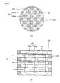
Figs. 1(A) and 1(B) are schematic illustrative views of ahoneycomb structure 1 of the present embodiment, and (A) is a front view and (B) is a partially enlarged view. -
Figs. 2(A) and 2(B) are schematic illustrative views of ahoneycomb structure 100 of a conventional example, and (A) is a front view and (B) is a section view. - Next, an embodiment of the present invention will be described based on the drawings.
A honeycomb structure of the present invention is used for producing an exhaust gas filter for purifying an exhaust gas discharged from an internal combustion engine, and is featured by a structure that will not cause a plugging failure during production of the exhaust gas filter. - The term plugging means closing an open end part of a through-hole (cell) provided in the honeycomb structure with a material of ceramics and the like. The material used for this plugging may or may not have air permeability; however, a material that does not allow passage of microparticles (such as soot) in the exhaust gas is preferably used. In other words, plugging with such a material makes it possible to prevent microparticles such as soot from flowing into a thorough-hole through this plugged end part. As a material used for plugging, for example, a material that does not allow passage of microparticles (such as soot) while having air permeability, as is a material forming walls of the honeycomb structure (
outer tube 2,inner tube 11, outsidecell partitioning wall 13, insidecell partitioning wall 12 inFig. 1 ), may be used. In this case, the material used for plugging may be the same with or different from the material of walls of the honeycomb structure. - Further, an exhaust gas filter produced from the honeycomb structure of the present invention is, for example, a filter (for example, DPF) that captures soot contained in an exhaust gas of a diesel engine or a gasoline engine, and is not particularly limited.
Also, by carrying a catalyst such as platinum in the material of the honeycomb structure of the present invention, it is also possible to produce a catalyst that purifies a harmful substance in the exhaust gas by using the honeycomb structure of the present invention. - First, an outline of a
honeycomb structure 1 of the present invention will be described.
In the following, a case where the cross-section of thehoneycomb structure 1 is circular, namely a case where thehoneycomb structure 1 is cylindrical will be described; however, thehoneycomb structure 1 of the present invention is not particularly limited to the cylinder and may have a cross-section of an approximate triangular shape (triangular shape with rounded apexes, a so-called triangular riceball shape), an elliptical shape, or a shape combining a straight line and a semicircle like a track for athletics and the like, and the shape of thehoneycomb structure 1 is not particularly limited.
In the following, a case where a basic shape of cross-section of a through-hole (cross-section orthogonal to the axial direction of the honeycomb structure), namely a basic shape of opening cross-section of a through-hole is quadrate (square or rectangle) will be described. However, the shape of opening cross-section of a through-hole in the honeycomb structure of the present invention is not limited to a precise quadrate, and may be an approximate quadrate, or may be a pentagon, a hexagon, an octagon, a circle and the like, and is not particularly limited.
Further, in the following, the honeycomb structure formed so that neighboring through-holes have an almost equivalent cross-section area of open cross-section, namely a honeycomb structure of so-called symmetric cells is described. However, the honeycomb structure of the present invention exerts similar action and effect even when the honeycomb structure is formed so that neighboring through-holes have different cross-section areas of open cross-section, namely the honeycomb structure has asymmetric cells. - As shown in
Fig. 1(A) , thehoneycomb structure 1 of the present invention is a tubular (cylindrical in the illustrated example) structure extending along the axial direction (the direction orthogonal to the sheet plane inFig. 1 ), and has a plurality of through-holes (10h, 13h, 20a, 20b, 20c, 25 and the like) penetrating between both axial ends along the axial direction.
Thehoneycomb structure 1 of the present invention is formed of ceramics that is fired after extrusion molding of a green body comprising a starting material powder, a molding aid, water and a optionally-added pore-forming agent, and wall surfaces forming the plurality of through-holes cell partitioning wall 12, outsidecell partitioning wall 13,outer tube 2,inner tube 11 and the like) are porous surfaces having pores with an average micropore size not more than 20 µm. The ceramics that forms the honeycomb structure of the present invention is not particularly limited, and examples thereof include aluminum titanate-based ceramics such as aluminum titanate, magnesium titanate and aluminum magnesium titanate. - As shown in
Fig. 1 , thehoneycomb structure 1 has a tubular (cylindrical in the illustrated example) outer tube (outer shell) 2, and has a plurality of partitioning walls on the inner side, and the plurality of through-holes outer tube 2 and the plurality of partitioning walls, and the part having through-holes formed by these partitioning walls is also referred to as a cell part. More specifically, thehoneycomb structure 1 has a double structure of theouter tube 2 and the inner tube (inner partitioning wall) 11 located on the inner side of theouter tube 2, and a first cell partitioning wall (outside cell partitioning wall) 13 is provided between theouter tube 2 and theinner tube 11, and a second cell partitioning wall (inside cell partitioning wall) 12 is formed on the inner side of theinner tube 11. Then, the outside through-hole 13h is formed by the outsidecell partitioning wall 13 and theouter tube 2, or by the outsidecell partitioning wall 13 and theinner tube 11, and the inside through-hole 10h is formed by insidecell partitioning walls 12. - The
inner tube 11 is a tubular (cylindrical in the illustrated example) wall provided on the inner side of the inner surface of theouter tube 2 as described above. Theinner tube 11 is formed so that the central axis thereof is coaxial to theouter tube 2, and the shape of cross-section that is orthogonal to the axial direction of the outer tube 2 (hereinafter, simply referred to as a cross-section) is similar in shape to theouter tube 2. - On the inner side of the
inner tube 11, a plurality of insidecell partitioning walls 12 that partition the interior space of theinner tube 11 are provided. Each of the plurality of insidecell partitioning walls 12 is formed so that its surface is parallel with the axial direction of theouter tube 2, and disposed so that the insidecell partitioning walls 12 that intersect with each other intersect at right angles. In other words, the space surrounded by the plurality of insidecell partitioning walls 12 forms the through-hole (hereinafter, referred to as an inside through-hole) 10h, and the plurality of insidecell partitioning walls 12 are disposed so that the shape of the cross-section of the inside through-hole 10h is quadrate, and the axial direction of the inside through-hole 10h is parallel with the axial direction of theouter tube 2. - Also, between the
inner tube 11 and theouter tube 2, a plurality of outsidecell partitioning walls 13 forming the through-hole (hereinafter, referred to as an outside through-hole) 13h are provided. Each of the plurality of outsidecell partitioning walls 13 is formed so that its surface is parallel with the axial direction of theouter tube 2.
This outsidecell partitioning wall 13 has an outside circumferential cell partitioning wall (outer circumferential partitioning wall) 13a which forms the outside through-holes 13h adjoiningly in the circumferential direction of theouter tube 2. The outside circumferentialcell partitioning wall 13a partitions the space between theouter tube 2 and theinner tube 11, and forms the outside through-holes 13h while they are adjoined in the direction along the inner surface of theouter tube 2. The outside circumferentialcell partitioning wall 13a is formed to be approximately orthogonal to the inner surface of theouter tube 2. In other words, at the position where a circle C1 that shares the center with theouter tube 2 intersects with the outsidecell partitioning wall 13 in the cross-section, tangent line of the circle C1 at that position and the outsidecell partitioning wall 13 are orthogonal to each other.
The outside circumferential cell partitioning wall may not be approximately orthogonal to the outer tube, and may be formed so that the shape of the cross-section of the outside through-holes neighboring in the circumferential direction of the outer tube are approximately trapezoidal. - In the
honeycomb structure 1 of the present invention, by plugging either one of end parts for all of the inside through-holes 10h and all of the outside through-holes 13h, it is possible to make thehoneycomb structure 1 into an exhaust gas filter (seeFig. 2 ).
When gas to be purified such as an exhaust gas is supplied from one end side of thehoneycomb structure 1 after plugging, the gas cannot flow out on the side of the other end of thehoneycomb structure 1 unless it essentially passes through either one of partitioning walls, so that it is possible to collect microparticles such as soot by the partitioning wall and to purify the exhaust gas. - In the
honeycomb structure 1 of the present invention, theinner tube 11 is provided, and the outsidecell partitioning wall 13 is provided between theinner tube 11 and theouter tube 2. In this manner, it is possible to make the outside through-hole 13h formed between theouter tube 2 and theinner tube 11 have a shape independent of the inside through-hole 10h in theinner tube 11, so that it is possible to keep the cross-section area of the outside through-hole 13h whose constituent is theouter tube 2 at a certain degree of size.
Therefore, it is possible to lower the possibility that the outside through-hole 13h whose constituent is theouter tube 2 collapses when thehoneycomb structure 1 is formed by extrusion molding and the like, and thus it is possible to keep the outer circumferential surface of thehoneycomb structure 1 at a predetermined accuracy.
Since the outside through-hole 13h whose constituent is theouter tube 2 does not collapse, the possibility that a streaky recess is formed on the outer circumferential surface of thehoneycomb structure 1 can also be decreased. As a result, it is possible to decrease the possibility that thehoneycomb structure 1 is damaged by heat shock and the like caused by the streaky recess. - Further, since the outside
cell partitioning wall 13 has the outside circumferentialcell partitioning wall 13a formed to be approximately orthogonal to the inner surface of theouter tube 2, even when such a force that compresses theouter tube 2 inward is applied onto the outer circumferential surface of theouter tube 2, the force can be supported by the outside circumferentialcell partitioning wall 13a. Therefore, it is possible to increase the durability of thehoneycomb structure 1 to the external force, and to decrease the possibility that thehoneycomb structure 1 is damaged by the external force. - In the case of the outside through-
hole 13h whose constituent is theouter tube 2, it is also possible to make the plugged material in the plugged part support the force applied onto thehoneycomb structure 1, so that it is possible to increase the strength of theouter tube 2, and to prevent damage on thehoneycomb structure 1.
Concretely, when thehoneycomb structure 1 of the present invention is used as an exhaust gas filter for purifying an exhaust gas discharged from an internal combustion engine, thehoneycomb structure 1 is housed in a metal case while it is wrapped with a heat-retaining material and the like. At this time, there is a case where an end edge of theouter tube 2 of thehoneycomb structure 1 comes into contact with the case, and due to this contact, theouter tube 2 may be recessed or chipped and the outside through-hole 13h may be damaged. However, when the outside through-hole 13h whose constituent is theouter tube 2 is plugged, even if such a contact occurs, damage on theouter tube 2, namely, damage on the outside through-hole 13h can be prevented. - Further, by plugging both ends of the outside through-
hole 13h formed between theouter tube 2 and theinner tube 11, it is possible to form a gas layer within the outside through-hole 13h. As a result, it is possible to make the outside through-hole 13h function as a heat-retaining layer for keeping the heat in the region on the inner side of theinner tube 11 inside theinner tube 11. - For example, when the
honeycomb structure 1 is used as a DPF, the following effects can be obtained by providing the heat-retaining layer.
In a DPF, microparticles such as soot captured by the partitioning wall forming the through-hole is heated to be oxidatively combusted, for example, by an exhaust gas, so that the partitioning wall is self-regenerated. For effectively conducting such self-regeneration, it is preferred that the temperature of the DPF in the cross-section of the region of capturing soot and the like is kept uniform.
However, since heat radiation to the outside air is large near theouter tube 2 of the DPF, when soot and the like is captured in this part, the soot and the like cannot be sufficiently combusted and self-regeneration of the partition wall cannot be achieved. This will lead occurrence of clogging and the like in the DPF, and functional deterioration of the DPF may be caused.
In light of this, the soot and the like is not captured near theouter tube 2 where the temperature is likely to decrease and the neighborhood of theouter tube 2 is made to function as a heat-retaining layer by providing the outside through-hole 13h plugged at both ends as described above, and the region for capturing soot and the like (indicating inside through-hole 10h and the like, hereinafter referred to as a filter region) can be surrounded by the outside through-hole 13h as a heat-retaining layer, so that it is possible to prevent heat generated by combustion of soot and the like in the filter region from escaping. Therefore, since the temperature in the cross-section can be uniformized in the filter region, it is possible to effectively achieve self-regeneration of the DPF and to prevent functional deterioration of the DPF due to clogging and the like. - When the outside through-
hole 13h formed between theouter tube 2 and theinner tube 11 is made to be a heat-retaining layer, both ends are not necessarily plugged. For example, it is possible to make the outside through-hole 13h to be a heat-retaining layer only by plugging the end part of the outside through-hole 13h on the inflow side of an exhaust gas. This is because when the end part on the inflow side of an exhaust gas is plugged, soot will not flow into the outside through-hole 13h and combustion of the soot will not occur in the outside through-hole 13h, so that it is possible to make the outside through-hole 13h function merely as an air layer. - Between the
outer tube 2 and theinner tube 11, a plurality of outside through-holes 13h may be arranged along the radial direction of thehoneycomb structure 1. That is, a plurality of heat-retaining layers may be provided in the radial direction of thehoneycomb structure 1 between theouter tube 2 and theinner tube 11, and in this case, the heat-retaining effect can be further improved.
For example, between theouter tube 2 and theinner tube 11, an intermediate tube (also referred to as a cell partitioning wall in the outside radial direction) 13b having the same central axis with these tubes may be provided as shown inFig. 1 . This intermediate tube (cell partitioning wall in the outside radial direction) 13b preferably has a cross-section shape similar to that of theouter tube 2. By providing the outside circumferentialcell partitioning wall 13a between theouter tube 2 and theintermediate tube 13b and between theintermediate tube 13b and theinner tube 11, respectively, it is possible to provide a plurality of heat-retaining layers in the radial direction and in the circumferential direction. - Next, a characteristic cell structure in the
honeycomb structure 1 of the present invention will be described.
That is, when through-holes (boundary part, also referred to as a cell having a small cross-section) 21a, 21b, 21c having cross-sections of irregular shapes (preferably approximate triangular shape or approximate trapezoidal shape) are formed by theinner tube 11 and the insidecell partitioning wall 12, on the inner side of (near) theinner tube 11, a plugging failure may occur in the through-holes having anirregular cross-section irregular cross-section hole 22a) that shares theinner tube 11 with the through-hole having anirregular cross-section 21a to form a first connected through-hole 20a, or the through-holes having anirregular cross-section 21b, 21c may be connected with another through-hole (namely, other through-hole having anirregular cross-section 22b, inside through-hole 22c and the like) that respectively shares the insidecell partitioning wall 12 to form second and third connected through-holes 20b, 20c. By connecting the through-holes having an irregular cross-section (cell having a small cross-section) 21a, 21b, 21c to neighboring through-holes (neighboring cell, also referred to as connecting part) 22a, 22b, 22c in this manner, it is possible to enlarge the opening sizes (cross-section areas) of the through-holes, and to prevent plugging failures of the through-holes holes - More preferably, the first connected through-
hole 20a is formed in the following manner. The through-hole having anirregular cross-section 21a surrounded by theinner tube 11 and the insidecell partitioning wall 12, which has an approximate triangular cross-section shape, is connected with the outside through-hole 22a closest to the apex of the sharpest angle of the through-hole having anirregular cross-section 21a. In a preferred example, a new insidecell partitioning wall 27 that extends inward in continuation with the outsidecell partitioning wall 13c forming the outside through-hole 22a and is parallel with the insidecell partitioning wall 12 is formed, and the connected through-hole 20a having an approximate pentagonal cross-section shape is formed. By such connection, it is possible to make the angle of the sharpest apex of the through-hole having an irregular cross-section 21 larger, and to prevent a plugging failure more securely. When the insidecell partitioning wall 12 is contained inside the connected through-hole 20a in forming the connected through-hole 20a having an approximate pentagonal cross-section shape, the inside cell partitioning wall located inside the connected through-hole 20a may be removed. - Also in a preferred example, when the new
cell partitioning wall 27 as described above forms a new through-hole having anirregular cross-section 23 having an approximate trapezoidal cross-section shape including thecell partitioning wall 27 as an shorter base, the new through-hole having anirregular cross-section 23 may be connected with a neighboring through-hole having anirregular cross-section 24 that shares acell partitioning wall 28 which is a longer base of the new through-hole 23, to form a connected through-hole 25. - The connected through-
holes inner tube 11 and the inside cell partitioning wall 12 (that may include the new inside cell partitioning wall 27). - As described above, by connecting the through-holes having an
irregular cross-section holes inner tube 11, it is possible to prevent a through-hole that is likely to cause a plugging failure from being formed near theinner tube 11. - Preferably, by providing the connected through-
holes holes
In this case, since all through-holes including the connected through-holes
For example, a honeycomb structure used in a DPF has about 200 to 400, and preferably about 250 to 350 through-holes in a region of 1 inch x 1 inch, and by making open area of each of all through-hole not less than 40% (about 0.4 to 0.64 mm2) of the average open area (about 1.0 to 1.6 mm2), it is possible to produce a DPF not causing a plugging failure. - Further, in all the through-holes, it is more preferred that the internal angle made by partitioning walls that form the through-hole and intersect with each other is not less than 30 degrees.
In this case, in plugging the through-holes honeycomb structure 1 is plugged for making it into a filter for purifying an exhaust gas discharged from an internal combustion engine. - In the above example, description has been made for a case where the
inner tube 11 is single; however, theinner tube 11 may be provided double or more. Also in this case, by forming the connected through-holes
Further, in the above example, description has been made for a case where theinner tube 11 is similar in shape to theouter tube 2; however, theinner tube 11 is not necessarily similar in shape to theouter tube 2. For example, theouter tube 2 may be in the shape of an ellipse or a riceball, or a track for athletics, and theinner tube 11 may be circular. - The honeycomb structure of the present invention is suitable for purifying an exhaust gas discharged from an internal combustion engine such as a diesel engine or a gasoline engine.
-
- 1
- honeycomb structure
- 2
- outer tube
- 10h
- inside through-hole
- 11
- inner tube
- 12
- inside cell partitioning wall
- 13
- outside cell partitioning wall
- 13a
- outside circumferential cell partitioning wall
- 13h
- outside through-hole
- 20a, 20b, 20c
- connected through-hole
- 21a, 21b, 21c
- through-hole having an irregular cross-section
Claims (8)
- A honeycomb structure used for a filter for purifying an exhaust gas discharged from an internal combustion engine, wherein
the honeycomb structure has a double structure of an outer tube and an inner tube,
on the inner side of the inner tube, an inside cell partitioning wall forming an inside through-hole is provided,
between the outer tube and inner tube, an outside cell partitioning wall forming an outside through-hole is provided,
the inner tube and the inside cell partitioning wall form a through-hole having an irregular cross-section, and
connected through-holes are formed by making at least one of the following connection patterns: the connection between a through-hole having an irregular cross-section and an outside through-hole, the through-holes sharing the inner tube, the connection between a through-hole having an irregular cross-section and another through-hole having an irregular cross-section, the through-holes sharing an inside cell partitioning wall, and the connection between a through-hole having an irregular cross-section and an inside through-hole, the through-holes sharing an inside cell partitioning wall. - The honeycomb structure according to claim 1, wherein a through-hole having an irregular cross-section having an approximate triangular or an approximate trapezoidal shape viewed in a cross-section of the outer tube is connected.
- The honeycomb structure according to claim 1, wherein a through-hole having an irregular cross-section having an approximate triangular shape viewed in a cross-section of the outer tube is connected with an outside through-hole closest to an apex of the sharpest angle of the through-hole having an irregular cross-section, and a new cell partitioning wall that extends inward in continuation with the outside cell partitioning wall forming the outside through-hole and is parallel with the inside cell partitioning wall is formed, and the shape of the connected through-hole is made to be an approximate pentagon viewed in a cross-section.
- The honeycomb structure according to claim 3, wherein when the new cell partitioning wall forms a new through-hole having an irregular cross-section having an approximate trapezoidal cross-section shape including the cell partitioning wall as an shorter base, the new through-hole having an irregular cross-section is connected with a neighboring through-hole having an irregular cross-section that shares the cell partitioning wall which is a longer base of the new through-hole.
- The honeycomb structure according to any one of claims 1 to 4, wherein in a cross-section of the outer tube, a through-hole having the smallest open area in all the through-holes has an open area not less than 40% of an average open area of all the through-holes.
- The honeycomb structure according to any one of claims 1 to 5, wherein in a cross-section of the outer tube, all interior angles of all the through-holes are not less than 30 degrees.
- The honeycomb structure according to any one of claims 1 to 6, wherein the outside cell partitioning wall includes an outside circumferential cell partitioning wall which forms the outside through-holes adjoiningly in the circumferential direction of the outer tube, and
the outside circumferential cell partitioning wall is formed to be approximately orthogonal to the outer tube. - The honeycomb structure according to any one of claims 1 to 7, wherein the outside through-hole is plugged at least one end thereof.
Applications Claiming Priority (2)
| Application Number | Priority Date | Filing Date | Title |
|---|---|---|---|
| JP2010008679A JP4825309B2 (en) | 2010-01-19 | 2010-01-19 | Honeycomb structure |
| PCT/JP2011/050716 WO2011090015A1 (en) | 2010-01-19 | 2011-01-18 | Honeycomb structure |
Publications (2)
| Publication Number | Publication Date |
|---|---|
| EP2527024A1 true EP2527024A1 (en) | 2012-11-28 |
| EP2527024A4 EP2527024A4 (en) | 2015-05-27 |
Family
ID=44306818
Family Applications (1)
| Application Number | Title | Priority Date | Filing Date |
|---|---|---|---|
| EP11734621.3A Withdrawn EP2527024A4 (en) | 2010-01-19 | 2011-01-18 | HONEYCOMB STRUCTURE |
Country Status (7)
| Country | Link |
|---|---|
| US (1) | US8852311B2 (en) |
| EP (1) | EP2527024A4 (en) |
| JP (1) | JP4825309B2 (en) |
| KR (1) | KR20120127418A (en) |
| CN (1) | CN102711949B (en) |
| BR (1) | BR112012017467A2 (en) |
| WO (1) | WO2011090015A1 (en) |
Families Citing this family (14)
| Publication number | Priority date | Publication date | Assignee | Title |
|---|---|---|---|---|
| JP2011224973A (en) * | 2010-03-19 | 2011-11-10 | Ibiden Co Ltd | Honeycomb structure |
| EP2634163A4 (en) * | 2010-10-26 | 2014-04-16 | Sumitomo Chemical Co | SEALING MATERIAL AND METHOD FOR MANUFACTURING A CERAMIC BONE BODY OF BEES |
| JP6041476B2 (en) | 2011-10-28 | 2016-12-07 | 住友化学株式会社 | Honeycomb structure |
| JP2013132879A (en) * | 2011-12-27 | 2013-07-08 | Sumitomo Chemical Co Ltd | Extrusion molding die |
| JP5916416B2 (en) * | 2012-02-10 | 2016-05-11 | 日本碍子株式会社 | Plugged honeycomb structure and honeycomb catalyst body using the same |
| EP2698190B1 (en) * | 2012-08-13 | 2018-06-27 | NGK Insulators, Ltd. | Plugged Honeycomb Structure |
| JP5708670B2 (en) * | 2013-01-18 | 2015-04-30 | 株式会社デンソー | Honeycomb structure |
| JP6137151B2 (en) * | 2014-03-26 | 2017-05-31 | 株式会社デンソー | Honeycomb structure |
| JP6438939B2 (en) * | 2014-03-31 | 2018-12-19 | 日本碍子株式会社 | Honeycomb structure |
| JP6485162B2 (en) * | 2014-07-24 | 2019-03-20 | 株式会社デンソー | Exhaust gas purification filter |
| JP6934702B2 (en) * | 2015-03-27 | 2021-09-15 | 株式会社デンソー | Exhaust gas purification filter |
| JP2018158445A (en) * | 2015-08-20 | 2018-10-11 | 住友化学株式会社 | Honeycomb structure and honeycomb filter |
| EP3775509B1 (en) | 2018-03-29 | 2023-09-27 | Corning Incorporated | Honeycomb body with varying cell densities and extrusion die for the manufacture thereof |
| CN110270189B (en) * | 2019-07-17 | 2023-12-29 | 西华大学 | Guide vane type high-pressure cyclone separator |
Family Cites Families (15)
| Publication number | Priority date | Publication date | Assignee | Title |
|---|---|---|---|---|
| US3853485A (en) * | 1972-12-11 | 1974-12-10 | Corning Glass Works | Core member for catalytic oxidation converter |
| EP0220702A3 (en) * | 1985-10-28 | 1989-07-26 | Mabco Limited | Method for the preparation of monoclonal antibody derived from immunoreactive trypsin |
| JPH0356354Y2 (en) | 1986-04-08 | 1991-12-18 | ||
| US5108685A (en) * | 1990-12-17 | 1992-04-28 | Corning Incorporated | Method and apparatus for forming an article with multi-cellular densities and/or geometries |
| CN2099367U (en) | 1991-07-02 | 1992-03-18 | 钱永怀 | Honeycomb type insulating device |
| JP3768550B2 (en) | 1994-03-11 | 2006-04-19 | 日本碍子株式会社 | Ceramic honeycomb structure |
| US5916133A (en) * | 1996-07-24 | 1999-06-29 | Corning Incorporated | Automotive hydrocarbon adsorber system |
| JP4159155B2 (en) * | 1998-01-22 | 2008-10-01 | 株式会社日本自動車部品総合研究所 | Ceramic honeycomb structure and extrusion mold |
| JP4680437B2 (en) * | 2001-07-13 | 2011-05-11 | 日本碍子株式会社 | Honeycomb structure |
| DE60233798D1 (en) | 2001-07-13 | 2009-11-05 | Ngk Insulators Ltd | WABENSTRUCKTURKÖRPER, WABENFILTER AND METHOD FOR THE PRODUCTION OF THE STRUCTURAL BODY AND THE FILTER |
| JP2005270755A (en) | 2004-03-24 | 2005-10-06 | Ngk Insulators Ltd | Honeycomb structure and manufacturing method thereof |
| CN100540111C (en) * | 2005-08-26 | 2009-09-16 | 揖斐电株式会社 | Honeycomb structure and method for manufacturing the same |
| JP2008018370A (en) * | 2006-07-14 | 2008-01-31 | Denso Corp | Ceramic catalyst body |
| DE102007053084A1 (en) * | 2007-11-07 | 2009-05-14 | Robert Bosch Gmbh | Filter element for filtering i.e. exhaust gases of diesel internal-combustion engine, has inlet channels and/or outlet channels limited by filter walls, where inlet channels and outlet channels are arranged in radial outer area of element |
| SE532906C2 (en) * | 2008-09-23 | 2010-05-04 | Scania Cv Abp | Hydrolysis catalyst with greater channel cross-section in the peripheral part than in the central part and methods for hydrolysis of a urea |
-
2010
- 2010-01-19 JP JP2010008679A patent/JP4825309B2/en not_active Expired - Fee Related
-
2011
- 2011-01-18 BR BR112012017467A patent/BR112012017467A2/en not_active IP Right Cessation
- 2011-01-18 WO PCT/JP2011/050716 patent/WO2011090015A1/en not_active Ceased
- 2011-01-18 CN CN201180006511.9A patent/CN102711949B/en not_active Expired - Fee Related
- 2011-01-18 US US13/522,195 patent/US8852311B2/en not_active Expired - Fee Related
- 2011-01-18 EP EP11734621.3A patent/EP2527024A4/en not_active Withdrawn
- 2011-01-18 KR KR1020127018913A patent/KR20120127418A/en not_active Withdrawn
Also Published As
| Publication number | Publication date |
|---|---|
| CN102711949B (en) | 2014-12-10 |
| JP2011147834A (en) | 2011-08-04 |
| JP4825309B2 (en) | 2011-11-30 |
| EP2527024A4 (en) | 2015-05-27 |
| US8852311B2 (en) | 2014-10-07 |
| KR20120127418A (en) | 2012-11-21 |
| CN102711949A (en) | 2012-10-03 |
| BR112012017467A2 (en) | 2016-04-19 |
| WO2011090015A1 (en) | 2011-07-28 |
| US20120317942A1 (en) | 2012-12-20 |
Similar Documents
| Publication | Publication Date | Title |
|---|---|---|
| US8852311B2 (en) | Honeycomb structure | |
| ES2277654T3 (en) | BEE NEST FILTER AND CERAMIC FILTER SET. | |
| US9566544B2 (en) | Honeycomb structure | |
| US10335727B2 (en) | Honeycomb filter | |
| JP2014200741A (en) | Wall flow type exhaust gas purification filter | |
| US20020189217A1 (en) | Exhaust gas purifying filter | |
| JP2017047372A (en) | Plugged honeycomb structure and plugged honeycomb segment | |
| JP2018066315A (en) | Sealed honeycomb structure | |
| CN108854319B (en) | Honeycomb filter | |
| JP5282030B2 (en) | Plugged honeycomb structure | |
| US20170197167A1 (en) | Honeycomb filter | |
| JP2013132879A (en) | Extrusion molding die | |
| JP6102114B2 (en) | Monolith type ceramic filter substrate and manufacturing method thereof | |
| JP2018065091A (en) | Plugged Honeycomb Structure | |
| US9322311B2 (en) | Honeycomb structure | |
| JP2013198884A (en) | Honeycomb segment body and ceramic filter provided therewith | |
| JP2009178705A (en) | Plugged honeycomb structure | |
| JP5851745B2 (en) | Honeycomb structure | |
| JP5816010B2 (en) | Honeycomb structure | |
| JP2012210610A (en) | Plugged honeycomb structure | |
| JP6887302B2 (en) | Honeycomb filter | |
| JP6491839B2 (en) | Honeycomb filter | |
| JP5816053B2 (en) | Honeycomb structure | |
| JP2013094721A (en) | Honeycomb structure |
Legal Events
| Date | Code | Title | Description |
|---|---|---|---|
| PUAI | Public reference made under article 153(3) epc to a published international application that has entered the european phase |
Free format text: ORIGINAL CODE: 0009012 |
|
| 17P | Request for examination filed |
Effective date: 20120806 |
|
| AK | Designated contracting states |
Kind code of ref document: A1 Designated state(s): AL AT BE BG CH CY CZ DE DK EE ES FI FR GB GR HR HU IE IS IT LI LT LU LV MC MK MT NL NO PL PT RO RS SE SI SK SM TR |
|
| DAX | Request for extension of the european patent (deleted) | ||
| RA4 | Supplementary search report drawn up and despatched (corrected) |
Effective date: 20150430 |
|
| RIC1 | Information provided on ipc code assigned before grant |
Ipc: B01J 35/04 20060101ALI20150423BHEP Ipc: F01N 3/02 20060101ALI20150423BHEP Ipc: B01D 39/20 20060101AFI20150423BHEP Ipc: B01D 46/00 20060101ALI20150423BHEP |
|
| 17Q | First examination report despatched |
Effective date: 20161013 |
|
| GRAP | Despatch of communication of intention to grant a patent |
Free format text: ORIGINAL CODE: EPIDOSNIGR1 |
|
| INTG | Intention to grant announced |
Effective date: 20170509 |
|
| STAA | Information on the status of an ep patent application or granted ep patent |
Free format text: STATUS: THE APPLICATION IS DEEMED TO BE WITHDRAWN |
|
| 18D | Application deemed to be withdrawn |
Effective date: 20170920 |