EP2527004B1 - Ultrasound probe - Google Patents
Ultrasound probe Download PDFInfo
- Publication number
- EP2527004B1 EP2527004B1 EP10843257.6A EP10843257A EP2527004B1 EP 2527004 B1 EP2527004 B1 EP 2527004B1 EP 10843257 A EP10843257 A EP 10843257A EP 2527004 B1 EP2527004 B1 EP 2527004B1
- Authority
- EP
- European Patent Office
- Prior art keywords
- probe
- housing
- ultrasound probe
- mounting hole
- ultrasound
- Prior art date
- Legal status (The legal status is an assumption and is not a legal conclusion. Google has not performed a legal analysis and makes no representation as to the accuracy of the status listed.)
- Active
Links
Images


Classifications
-
- A—HUMAN NECESSITIES
- A61—MEDICAL OR VETERINARY SCIENCE; HYGIENE
- A61N—ELECTROTHERAPY; MAGNETOTHERAPY; RADIATION THERAPY; ULTRASOUND THERAPY
- A61N7/00—Ultrasound therapy
- A61N7/02—Localised ultrasound hyperthermia
-
- B—PERFORMING OPERATIONS; TRANSPORTING
- B06—GENERATING OR TRANSMITTING MECHANICAL VIBRATIONS IN GENERAL
- B06B—METHODS OR APPARATUS FOR GENERATING OR TRANSMITTING MECHANICAL VIBRATIONS OF INFRASONIC, SONIC, OR ULTRASONIC FREQUENCY, e.g. FOR PERFORMING MECHANICAL WORK IN GENERAL
- B06B1/00—Methods or apparatus for generating mechanical vibrations of infrasonic, sonic, or ultrasonic frequency
- B06B1/02—Methods or apparatus for generating mechanical vibrations of infrasonic, sonic, or ultrasonic frequency making use of electrical energy
- B06B1/06—Methods or apparatus for generating mechanical vibrations of infrasonic, sonic, or ultrasonic frequency making use of electrical energy operating with piezoelectric effect or with electrostriction
- B06B1/0607—Methods or apparatus for generating mechanical vibrations of infrasonic, sonic, or ultrasonic frequency making use of electrical energy operating with piezoelectric effect or with electrostriction using multiple elements
- B06B1/0622—Methods or apparatus for generating mechanical vibrations of infrasonic, sonic, or ultrasonic frequency making use of electrical energy operating with piezoelectric effect or with electrostriction using multiple elements on one surface
- B06B1/0637—Spherical array
-
- A—HUMAN NECESSITIES
- A61—MEDICAL OR VETERINARY SCIENCE; HYGIENE
- A61N—ELECTROTHERAPY; MAGNETOTHERAPY; RADIATION THERAPY; ULTRASOUND THERAPY
- A61N7/00—Ultrasound therapy
- A61N2007/0056—Beam shaping elements
- A61N2007/0065—Concave transducers
-
- A—HUMAN NECESSITIES
- A61—MEDICAL OR VETERINARY SCIENCE; HYGIENE
- A61N—ELECTROTHERAPY; MAGNETOTHERAPY; RADIATION THERAPY; ULTRASOUND THERAPY
- A61N7/00—Ultrasound therapy
- A61N2007/0078—Ultrasound therapy with multiple treatment transducers
-
- A—HUMAN NECESSITIES
- A61—MEDICAL OR VETERINARY SCIENCE; HYGIENE
- A61N—ELECTROTHERAPY; MAGNETOTHERAPY; RADIATION THERAPY; ULTRASOUND THERAPY
- A61N7/00—Ultrasound therapy
- A61N2007/0086—Beam steering
- A61N2007/0095—Beam steering by modifying an excitation signal
Definitions
- the present invention relates to an ultrasound treatment system using high-intensity focused ultrasound and, more particularly, to an ultrasound probe of the ultrasound treatment system which easily performs manufacturing and maintenance processes.
- HIFU treatment is increasing in clinical applications.
- HIFU treatment are being used for liver cancer, bone sarcoma, breast cancer, pancreas cancer, kidney cancer, soft tissue tumor, pelvic tumor, and the like.
- Such an ultrasound treatment apparatus employs in general an ultrasound probe using a sphere focusing. Ultrasound emitted from all points of the ultrasound probe proceeds toward the center of a sphere, thus forming focused ultrasound.
- An emitter of the ultrasound treatment apparatus emits ultrasound from the outside to the inside of a body, and this forms a high-energy focused point by being focused during emission and transmission.
- Highly intensive and continuous ultrasound energy is applied to a target region of a treatment subject. Excessively high temperature (65 ⁇ 100°C), cavitation effect, mechanical effect and acoustic-chemical effect may selectively cause coagulative necrosis of ailing organization and also prevent proliferation, invasion and metastasis of tumors.
- This ultrasound treatment apparatus requires more exact, safer, and more effective localization of a focused point during HIFU treatment and also requires more convenient operability for locating the target.
- Document EP 0 310 380 A2 discloses an ultrasound probe having the features of the preamble of claim 1.
- an object of the present invention is to provide an ultrasound probe with improved ultrasound and heat dissipation characteristics.
- Another aim of the present invention is to provide an ultrasound probe which can easily perform manufacturing and maintenance processes.
- an ultrasound probe that comprises a housing and a plurality of probe units.
- the housing is recessed inward from edges at an upper part thereof and has a plurality of mounting holes formed apart from a center and to the edges.
- the plurality of probe units are installed in the mounting holes, respectively, so that a spherical surface for a spherical focusing is formed at the upper part of the housing.
- each of the probe units includes a connection bar having electric and thermal conductivity, a first connection pin formed on a lower surface of the connection bar and protruded from a lower part of the housing through the mounting hole of the housing, a rear block formed on an upper surface of the connection bar and having an inclined plane for forming the spherical surface, a piezoelectric wafer formed on the inclined plane of the rear block, and a plurality of acoustic matching layers formed on an upper surface of the piezoelectric wafer.
- each of the probe units may further include a grounding film formed on the acoustic matching layer and forming the spherical surface.
- the mounting holes may be arranged in a radial form in the housing.
- the mounting holes may be arranged along ring-shaped coaxial regions which are disposed beyond a certain radius from the center of the spherical surface and to the edges of the spherical surface.
- stacks of the rear block, the piezoelectric wafer, the acoustic matching layer and the grounding film formed on the first connection pin may have a first length at a first region toward the center of the housing and a second length at a second region toward the edges of the housing, the first length being shorter than the second length.
- the probe units arranged along the same ring-shaped region may have the same shape.
- the probe units may have increasing length according as positions thereof become more distant from the center of the housing, and the first connection pins protruded from the lower part of the housing may be all the same length.
- connection bars located at different ring-shaped regions may have different lengths which increase according as positions thereof become closer to the edges and become more distant from the center of the housing.
- connection bar of the probe unit may have at a lower part thereof a first pin hole into which the first connection pin is inserted.
- the rear block may have a second connection pin extruded from a lower surface thereof, and the connection bar of the probe unit may have at an upper part thereof a second pin hole into which the second connection pin is inserted.
- the mounting hole includes a first mounting hole formed at the lower part of the housing such that the first connection pin is inserted into the first mounting hole and protruded from the first mounting hole, a second mounting hole vertically connected to the first mounting hole such that the connection bar is inserted into the second mounting hole, and a third mounting hole vertically connected to the second mounting hole such that the rear block is inserted into the third mounting hole.
- connection bar of the probe unit may be formed of copper.
- the rear block of the probe unit may be formed of graphite
- the piezoelectric wafer may be formed of PZT or PMN-PT
- the grounding film may be formed of polyimide film.
- the ultrasound probe of the present invention may further comprise a cover layer covering the spherical surface formed by the plurality of probe units.
- the ultrasound probe according to the present invention may enhance ultrasound characteristics (acoustic characteristics) through the control of the plurality of probe units. Also, since the probe units are arranged along a plurality of ring-shaped coaxial regions which are disposed beyond a certain radius from the center of the spherical surface and to the edges of the spherical surface, and since each ring-shaped region has a plurality of divided sections, acoustic loss caused by empty spaces between the probe units may be prevented and thus ultrasound characteristics may be enhanced. And also, since the probe units located at adjacent ring-shaped regions are arranged differently in zigzags, ultrasound characteristics may be enhanced and further a unifying force between the probe units may be improved.
- the probe unit has at the lower part thereof the connection pin and has at the upper part thereof a stack structure of the rear block, the piezoelectric wafer, the acoustic matching layer, and the grounding film via the connection bar of copper. Therefore, heat dissipation efficiency may be enhanced through the connection bar.
- the ultrasound probe according to this invention is manufactured by inserting the probe unit into the mounting hole formed in the housing, so a manufacturing process is simplified. Also, since the probe unit is detachable from the housing, a maintenance process is allowed for each of the probe units. Therefore, when some parts of the ultrasound probe are defective, there is no need to replace the entire ultrasound probe and hence unnecessary cost loss may be prevented.
- the ultrasound probe according to this invention can be connected to the main body of the ultrasound treatment system using the connector cable of a connector coupling manner rather than a wiring manner. Therefore, the ultrasound treatment system has an advantage of simply performing a maintenance process for the ultrasound probe by detaching the ultrasound probe from the connector cable.
- an ultrasound probe 100 is connected to a main body of an ultrasound treatment system in a connector coupling manner using a connector cable 200.
- the ultrasound probe 100 includes a housing 10, a plurality of probe units 20 installed in the housing 10 to form a spherical surface at the upper part of the housing 10, and a cover layer 40 covering the spherical surface formed by the plurality of probe units 20.
- the upper surface of the ultrasound probe 100 is formed with a bowl-shaped spherical surface in order to offer a spherical focusing.
- first connection pins 22 of the probe unit 20 are uniformly extruded from the lower surface of the housing 10.
- a through hole 14 is formed at the central part of the housing 10.
- the cover layer 40 protects the spherical surface formed by the plurality of probe units 20. Silicone material may be used for the cover layer 40.
- the connector cable 200 includes a connector 110 having connection holes 112 which correspond to the first connection pins 22, and a cable 120 which electrically couples the first connection pins 22 inserted into the connector 110 to the main body of the ultrasound treatment system.
- the main body of the ultrasound treatment system applies a driving signal to the ultrasound probe 100 through the connector cable 200, and in response to the driving signal the ultrasound probe 100 generates high-intensity focused ultrasound required for ultrasound treatment.
- the connector 110 of the connector cable 200 has, at the central part thereof, a through hole 114 which corresponds to a through hole 14 of the housing 10.
- a through hole 114 which corresponds to a through hole 14 of the housing 10.
- any hole with a limited depth may be formed or no hole may be formed.
- the ultrasound probe 100 can be connected to the main body of the ultrasound treatment system using the connector cable 200 of a connector coupling manner rather than a wiring manner. Therefore, the ultrasound treatment system has an advantage of simply performing a maintenance process for the ultrasound probe 100 by detaching the ultrasound probe 100 from the connector cable 200.
- the ultrasound probe 100 includes the housing 10 and the probe unit 20 and may further include the cover layer 40.
- the housing 10 is recessed inward from edges at the upper part thereof, and a plurality of mounting holes 12 are formed apart from the center and to the edges. Additionally, the probe units 20 are installed in the mounting holes 12, respectively, so that a spherical surface for a spherical focusing is formed at the upper part of the housing 10.
- the housing 10 has a cylindrical shape, has the through hole 14 formed at the central part thereof, and has the spherical upper part around the central part.
- the housing 10 may be formed of rigid plastic material such as polyethylene (PE), polypropylene (PP), polystyrene (PS), polyethylene-terephthalate (PET), acrylonitrile-butandiene-styrene (ABS), or the like.
- the mounting holes 12 are arranged in a radial form in the housing 10. Specifically, the mounting holes 12 may be arranged along ring-shaped coaxial regions which are disposed beyond a certain radius from the center of the spherical surface and to the edges of the spherical surface. Each mounting hole 12 is parallel to the central axis of the housing 10 and has the first mounting hole 12a, the second mounting hole 12b, and the third mounting hole 12c. From the first mounting hole 12a to the third mounting hole 12c, the diameter of hole is gradually increased. A related description will be described later.
- the probe units 20 are inserted into the mounting holes 12 of the housing 10, respectively.
- the lower end is protruded from the lower part of the housing 10, and the upper end is protruded from the upper part of the housing 10, forming the spherical surface.
- the probe unit 20 has a connection bar 21, the first connection pin 22, a rear block 23, a piezoelectric wafer 25, and an acoustic matching layer 27, and may further have a grounding film 29.
- a second connection pin 28 is formed on the lower surface of the rear block 23.
- connection bar 21 is formed of electrically and thermally conductive material and has a pole shape. Copper or any other metal having good electric and thermal conductivity may be used for the connection bar 21.
- the first connection pin 22 is formed on the lower surface of the connection bar 21 and protruded from the lower part of the housing 10 through the mounting hole 12 of the housing 10.
- the connection bar 21 has the first pin hole 24 which is formed in the lower surface thereof and into which the first connection pin 22 is partially inserted.
- the first connection pin 22 may be integrated with the connection bar 21.
- the rear block 23 is formed on the upper surface of the connection bar 21, and the upper part of the rear block 23 forms an inclined plane so as to ultimately form the spherical surface.
- the rear block 23 absorbs unnecessary ultrasound signals which travel from the piezoelectric wafer 25 to the rear block 23.
- the rear block 23 may be formed of rubber or graphite which has a good sound absorption property. As shown in FIG. 6 , the rear block 23 has a form partially removed from a rectangular parallelepiped and thus has a cross section of trapezoid form. A removed surface forms the inclined plane of the rear block 23.
- the second connection pin 28 integrated with the rear block 23 is extruded from the lower surface of the rear block 23.
- the second pin hole 26 is formed in the upper surface of the connection bar 21, so that the second connection pin 28 can be inserted into the second pin hole 26. Therefore, the rear block 23 is joined to the connection bar 21 via the second connection pin 28 inserted into the second pin hole 26.
- the lower surface of the rear block 23 adheres closely to the upper surface of the connection bar 21.
- the first and second connection pins 22 and 28 may be fixedly inserted into the first and second pin holes 24 and 26 in a forced insertion manner or using electrically conductive adhesive.
- the piezoelectric wafer 25, the acoustic matching layer 27 and the grounding film 29 are sequentially formed on the inclined plane of the rear block 23 so as to be parallel to the inclined plane. Namely, each of the piezoelectric wafer 25, the acoustic matching layer 27 and the grounding film 29 has a rectangular parallelepiped form having upper and lower surfaces corresponding to the inclined plane of the rear block 23 and is sequentially stacked. Therefore, in an embodiment, a stack of the piezoelectric wafer 25, the acoustic matching layer 27 and the grounding film 29 is laterally protruded from the lower end of the inclined plane as shown. Alternatively, the stack may be formed so as not to exceed the lateral surface of the rear block 23. In this case, each of the piezoelectric wafer 25, the acoustic matching layer 27 and the grounding film 29 has upper and lower surfaces corresponding to the inclined plane of the rear block 23 and has a cross section of trapezoid form.
- the piezoelectric wafer 25 is formed on the inclined plane of the rear block 23 and generates ultrasound.
- the piezoelectric wafer 25 is divided into a plurality of devices in a scan direction. Ceramic material such as PZT or PMN-PT may be used for the piezoelectric wafer 25.
- the acoustic matching layer 27 is formed on the upper surface of the piezoelectric wafer 25 and performs an acoustic matching function for the ultrasound generated from the piezoelectric wafer 25.
- the acoustic matching layer 27 may be composed of at least one layer. Also, the acoustic matching layer 27 may be formed of metal powder, ceramic powder, silicon wafer, and the like.
- the grounding film 29 is formed on the acoustic matching layer 27 and forms a spherical surface.
- a polyimide film may be used for the grounding film 29.
- the probe unit 20 is installed in each mounting hole 12 of the housing 10, and the probe units 20 arranged along the same ring-shaped region have the same shape.
- the mounting holes 12 have increasing length according as their positions become more distant from the center of the housing 10.
- the probe units 20 have also increasing length as shown in FIG. 3 , but the first connection pins 22 protruded from the lower part of the housing 10 are all the same length.
- the connection bars 21 located at different ring-shaped regions have different lengths which increase according as their positions become closer to the edges, namely, become more distant from the center of the housing 10.
- the mounting hole 12 of the housing 10 into which the probe unit 20 is fixedly installed includes the first to third mounting holes 12a, 12b and 12c.
- the first mounting hole 12a is formed at the lower part of the housing 10, and the first connection pin 22 is inserted thereinto and protruded therefrom.
- the second mounting hole 12b is vertically connected to the first mounting hole 12a, and the connection bar 21 is inserted thereinto.
- the lower surface of the connection bar 21 is mounted on the bottom of the second mounting hole 12b communicating with the first mounting hole 12a.
- the third mounting hole 12c is vertically connected to the second mounting hole 12b, and the rear block 23 is inserted thereinto.
- the third mounting hole 12c accommodates a part of the rear block 23 of the probe unit 20, so that the piezoelectric wafer 25, the acoustic matching layer 27 and the grounding film 29 stacked on the rear block 23 are located out of the third mounting hole 12c.
- the mounting hole 12 of the housing 10 is formed to be adapted for the shape of the probe unit 20.
- each of the first connection pin 22 and the connection bar 21 of the probe unit 20 has a circular cross section in a plan view
- each of the first and second mounting holes 12a and 12b is formed to have a circular cross section in a plan view.
- the third mounting hole 12c is formed to have a rectangular cross section in a plan view.
- the probe unit 20 may be fixedly inserted into the mounting hole 12 of the housing 10 through adhesive or in a forced insertion manner. Also, the probe unit 20 may be installed in the mounting hole 12 of the housing 10 in a screw coupling manner. And also, any other well known manners may be used for installing the probe unit 20 into the mounting hole 12 of the housing 10.
- the ultrasound probe 100 may enhance ultrasound characteristics (acoustic characteristics) through the control of the plurality of probe units 20. Also, since the probe units 20 are arranged along a plurality of ring-shaped coaxial regions which are disposed beyond a certain radius from the center of the spherical surface and to the edges of the spherical surface, and since each ring-shaped region has a plurality of divided sections, acoustic loss caused by empty spaces between the probe units 20 may be prevented and thus ultrasound characteristics may be enhanced. And also, since the probe units 20 located at adjacent ring-shaped regions are arranged differently in zigzags, ultrasound characteristics may be enhanced and further a unifying force between the probe units 20 may be improved.
- the probe unit 20 of the ultrasound probe 100 has at the lower part thereof the first connection pin 22 and has at the upper part thereof a stack structure of the rear block 23, the piezoelectric wafer 25, the acoustic matching layer 27, and the grounding film 29 via the connection bar 22 of copper. Therefore, heat dissipation efficiency may be enhanced through the connection bar 22.
- the ultrasound probe 100 is manufactured by inserting the probe unit 20 into the mounting hole 12 formed in the housing 10, so a manufacturing process is simplified. Also, since the probe unit 20 is detachable from the housing 10, a maintenance process is allowed for each of the probe units 20. Therefore, when some parts of the ultrasound probe 100 are defective, there is no need to replace the entire ultrasound probe 100 and hence unnecessary cost loss may be prevented.
- the housing 10 and the plurality of probe units 20 to be inserted into the mounting holes 12 of the housing 10 are prepared.
- the probe units 20 are inserted into the mounting holes 12 located near the through hole 14 of the housing 10 and fixedly installed through adhesive. At this time, the inserted probe units 20 form a ring shape. Then, in the same manner, other probe units 20 are inserted and fixedly installed in the next mounting holes 12 which are outwardly adjacent to the previously inserted probe units 20. In this manner, the probe units 20 are inserted and fixedly installed in all the mounting holes 12 of the housing 10 sequentially from the near side of the through hole 14 to the far side.
- the cover layer 40 is covered on a spherical surface formed by the plurality of probe units 20, and thus a manufacturing process of the ultrasound probe 100 is completed.
- the cover layer 40 may be formed in an adhering or coating manner to cover the spherical surface.
- the reason the probe units 20 are installed from the inner side of the housing 10 is that a stack of the piezoelectric wafer 25, the acoustic matching layer 27 and the grounding film 29 is laterally protruded from the lower end of the inclined plane of the rear block 23.
- the probe unit having the stack of the piezoelectric wafer, the acoustic matching layer and the grounding film without exceeding the lateral surface of the rear block, there is no need to install the probe units in a sequential manner discussed above. Namely, since the probe unit has the stack which is not protruded from the lateral surface of the rear block, the probe units may be inserted and installed in the housing regardless of the order if only the same probe units are arranged in the same ring-shaped region.
Landscapes
- Health & Medical Sciences (AREA)
- Engineering & Computer Science (AREA)
- Life Sciences & Earth Sciences (AREA)
- Biomedical Technology (AREA)
- Nuclear Medicine, Radiotherapy & Molecular Imaging (AREA)
- Radiology & Medical Imaging (AREA)
- Mechanical Engineering (AREA)
- Animal Behavior & Ethology (AREA)
- General Health & Medical Sciences (AREA)
- Public Health (AREA)
- Veterinary Medicine (AREA)
- Ultra Sonic Daignosis Equipment (AREA)
- Transducers For Ultrasonic Waves (AREA)
- Surgical Instruments (AREA)
Description
- The present invention relates to an ultrasound treatment system using high-intensity focused ultrasound and, more particularly, to an ultrasound probe of the ultrasound treatment system which easily performs manufacturing and maintenance processes.
- Recently, ultrasound treatment has increased the range of use. With the growth of ultrasound treatment, a specific ultrasound treatment, especially high-intensity focused ultrasound (HIFU), is applied to damaging dose in order to effectively cure many types of disease, especially tumor. In comparison with conventional surgical operation and chemotherapy, HIFU treatment may hardly traumatize patients and also realize non-invasive treatment. Therefore, HIFU treatment is increasing in clinical applications. For example, HIFU treatment are being used for liver cancer, bone sarcoma, breast cancer, pancreas cancer, kidney cancer, soft tissue tumor, pelvic tumor, and the like.
- Such an ultrasound treatment apparatus employs in general an ultrasound probe using a sphere focusing. Ultrasound emitted from all points of the ultrasound probe proceeds toward the center of a sphere, thus forming focused ultrasound. An emitter of the ultrasound treatment apparatus emits ultrasound from the outside to the inside of a body, and this forms a high-energy focused point by being focused during emission and transmission. Highly intensive and continuous ultrasound energy is applied to a target region of a treatment subject. Excessively high temperature (65∼100°C), cavitation effect, mechanical effect and acoustic-chemical effect may selectively cause coagulative necrosis of ailing organization and also prevent proliferation, invasion and metastasis of tumors.
- This ultrasound treatment apparatus requires more exact, safer, and more effective localization of a focused point during HIFU treatment and also requires more convenient operability for locating the target.
-
Document EP 0 310 380 A2 discloses an ultrasound probe having the features of the preamble of claim 1. - Accordingly, an object of the present invention is to provide an ultrasound probe with improved ultrasound and heat dissipation characteristics.
- Another aim of the present invention is to provide an ultrasound probe which can easily perform manufacturing and maintenance processes.
- The above object is solved by an ultrasound probe of claim 1. Further developments are stated in the dependent claims.
- Thus, there is provided an ultrasound probe that comprises a housing and a plurality
of probe units. The housing is recessed inward from edges at an upper part thereof and has a plurality of mounting holes formed apart from a center and to the edges. The plurality of probe units are installed in the mounting holes, respectively, so that a spherical surface for a spherical focusing is formed at the upper part of the housing. - In the ultrasound probe of the present invention, each of the probe units includes a connection bar having electric and thermal conductivity, a first connection pin formed on a lower surface of the connection bar and protruded from a lower part of the housing through the mounting hole of the housing, a rear block formed on an upper surface of the connection bar and having an inclined plane for forming the spherical surface, a piezoelectric wafer formed on the inclined plane of the rear block, and a plurality of acoustic matching layers formed on an upper surface of the piezoelectric wafer.
- In the ultrasound probe of the present invention, each of the probe units may further include a grounding film formed on the acoustic matching layer and forming the spherical surface.
- In the ultrasound probe of the present invention, the mounting holes may be arranged in a radial form in the housing.
- In the ultrasound probe of the present invention, the mounting holes may be arranged along ring-shaped coaxial regions which are disposed beyond a certain radius from the center of the spherical surface and to the edges of the spherical surface.
- In the ultrasound probe of the present invention, stacks of the rear block, the piezoelectric wafer, the acoustic matching layer and the grounding film formed on the first connection pin may have a first length at a first region toward the center of the housing and a second length at a second region toward the edges of the housing, the first length being shorter than the second length.
- In the ultrasound probe of the present invention, the probe units arranged along the same ring-shaped region may have the same shape.
- In the ultrasound probe of the present invention, the probe units may have increasing length according as positions thereof become more distant from the center of the housing, and the first connection pins protruded from the lower part of the housing may be all the same length.
- In the ultrasound probe of the present invention, the connection bars located at different ring-shaped regions may have different lengths which increase according as positions thereof become closer to the edges and become more distant from the center of the housing.
- In the ultrasound probe of the present invention, the connection bar of the probe unit may have at a lower part thereof a first pin hole into which the first connection pin is inserted.
- In the ultrasound probe of the present invention, the rear block may have a second connection pin extruded from a lower surface thereof, and the connection bar of the probe unit may have at an upper part thereof a second pin hole into which the second connection pin is inserted.
- In the ultrasound probe of the present invention, the mounting hole includes a first mounting hole formed at the lower part of the housing such that the first connection pin is inserted into the first mounting hole and protruded from the first mounting hole, a second mounting hole vertically connected to the first mounting hole such that the connection bar is inserted into the second mounting hole, and a third mounting hole vertically connected to the second mounting hole such that the rear block is inserted into the third mounting hole.
- In the ultrasound probe of the present invention, the connection bar of the probe unit may be formed of copper.
- In the ultrasound probe of the present invention, the rear block of the probe unit may be formed of graphite, the piezoelectric wafer may be formed of PZT or PMN-PT, and the grounding film may be formed of polyimide film.
- The ultrasound probe of the present invention may further comprise a cover layer covering the spherical surface formed by the plurality of probe units.
- Since a plurality of probe units are installed in the housing and further a spherical surface is formed at the upper part of the housing, the ultrasound probe according to the present invention may enhance ultrasound characteristics (acoustic characteristics) through the control of the plurality of probe units. Also, since the probe units are arranged along a plurality of ring-shaped coaxial regions which are disposed beyond a certain radius from the center of the spherical surface and to the edges of the spherical surface, and since each ring-shaped region has a plurality of divided sections, acoustic loss caused by empty spaces between the probe units may be prevented and thus ultrasound characteristics may be enhanced. And also, since the probe units located at adjacent ring-shaped regions are arranged differently in zigzags, ultrasound characteristics may be enhanced and further a unifying force between the probe units may be improved.
- The probe unit has at the lower part thereof the connection pin and has at the upper part thereof a stack structure of the rear block, the piezoelectric wafer, the acoustic matching layer, and the grounding film via the connection bar of copper. Therefore, heat dissipation efficiency may be enhanced through the connection bar.
- The ultrasound probe according to this invention is manufactured by inserting the probe unit into the mounting hole formed in the housing, so a manufacturing process is simplified. Also, since the probe unit is detachable from the housing, a maintenance process is allowed for each of the probe units. Therefore, when some parts of the ultrasound probe are defective, there is no need to replace the entire ultrasound probe and hence unnecessary cost loss may be prevented.
- Since the connection pins are extruded from the lower part of the housing, the ultrasound probe according to this invention can be connected to the main body of the ultrasound treatment system using the connector cable of a connector coupling manner rather than a wiring manner. Therefore, the ultrasound treatment system has an advantage of simply performing a maintenance process for the ultrasound probe by detaching the ultrasound probe from the connector cable.
-
-
FIG. 1 is a perspective view illustrating a state in which a connector cable is connected to an ultrasound probe in accordance with an embodiment of the present invention. -
FIG. 2 is a perspective view illustrating the ultrasound probe in accordance with an embodiment of the present invention. -
FIG. 3 is a cross-sectional view illustrating the ultrasound probe shown inFIG. 2 . -
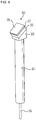
FIG. 4 is a perspective view illustrating a probe unit shown inFIG. 2 . -
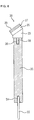
FIG. 5 is a perspective view illustrating the probe unit shown inFIG. 4 . -
FIG. 6 is a cross-sectional view illustrating the probe unit shown inFIG. 5 . - Embodiments of the present invention will now be described more fully with reference to the accompanying drawings.
- As shown in
FIGS. 1 to 3 , anultrasound probe 100 according to an embodiment of the present invention is connected to a main body of an ultrasound treatment system in a connector coupling manner using aconnector cable 200. - The
ultrasound probe 100 includes ahousing 10, a plurality ofprobe units 20 installed in thehousing 10 to form a spherical surface at the upper part of thehousing 10, and acover layer 40 covering the spherical surface formed by the plurality ofprobe units 20. Namely, the upper surface of theultrasound probe 100 is formed with a bowl-shaped spherical surface in order to offer a spherical focusing. In theultrasound probe 100,first connection pins 22 of theprobe unit 20 are uniformly extruded from the lower surface of thehousing 10. A throughhole 14 is formed at the central part of thehousing 10. Thecover layer 40 protects the spherical surface formed by the plurality ofprobe units 20. Silicone material may be used for thecover layer 40. - Additionally, the
connector cable 200 includes aconnector 110 havingconnection holes 112 which correspond to the first connection pins 22, and acable 120 which electrically couples the first connection pins 22 inserted into theconnector 110 to the main body of the ultrasound treatment system. The main body of the ultrasound treatment system applies a driving signal to theultrasound probe 100 through theconnector cable 200, and in response to the driving signal theultrasound probe 100 generates high-intensity focused ultrasound required for ultrasound treatment. - As shown, the
connector 110 of theconnector cable 200 has, at the central part thereof, a throughhole 114 which corresponds to a throughhole 14 of thehousing 10. However, instead of the through hole, any hole with a limited depth may be formed or no hole may be formed. - Since the first connection pins 22 are extruded from the lower part of the
housing 10, theultrasound probe 100 according to an embodiment of this invention can be connected to the main body of the ultrasound treatment system using theconnector cable 200 of a connector coupling manner rather than a wiring manner. Therefore, the ultrasound treatment system has an advantage of simply performing a maintenance process for theultrasound probe 100 by detaching theultrasound probe 100 from theconnector cable 200. - As shown in
FIGS. 1 to 6 , theultrasound probe 100 according to an embodiment of this invention includes thehousing 10 and theprobe unit 20 and may further include thecover layer 40. Thehousing 10 is recessed inward from edges at the upper part thereof, and a plurality of mountingholes 12 are formed apart from the center and to the edges. Additionally, theprobe units 20 are installed in the mounting holes 12, respectively, so that a spherical surface for a spherical focusing is formed at the upper part of thehousing 10. - Particularly, the
housing 10 has a cylindrical shape, has the throughhole 14 formed at the central part thereof, and has the spherical upper part around the central part. Thehousing 10 may be formed of rigid plastic material such as polyethylene (PE), polypropylene (PP), polystyrene (PS), polyethylene-terephthalate (PET), acrylonitrile-butandiene-styrene (ABS), or the like. - The mounting holes 12 are arranged in a radial form in the
housing 10. Specifically, the mountingholes 12 may be arranged along ring-shaped coaxial regions which are disposed beyond a certain radius from the center of the spherical surface and to the edges of the spherical surface. Each mountinghole 12 is parallel to the central axis of thehousing 10 and has the first mountinghole 12a, thesecond mounting hole 12b, and the third mountinghole 12c. From the first mountinghole 12a to the third mountinghole 12c, the diameter of hole is gradually increased. A related description will be described later. - The
probe units 20 are inserted into the mountingholes 12 of thehousing 10, respectively. In each of theprobe units 20, the lower end is protruded from the lower part of thehousing 10, and the upper end is protruded from the upper part of thehousing 10, forming the spherical surface. Theprobe unit 20 has aconnection bar 21, thefirst connection pin 22, arear block 23, apiezoelectric wafer 25, and anacoustic matching layer 27, and may further have agrounding film 29. Asecond connection pin 28 is formed on the lower surface of therear block 23. - The
connection bar 21 is formed of electrically and thermally conductive material and has a pole shape. Copper or any other metal having good electric and thermal conductivity may be used for theconnection bar 21. - The
first connection pin 22 is formed on the lower surface of theconnection bar 21 and protruded from the lower part of thehousing 10 through the mountinghole 12 of thehousing 10. Theconnection bar 21 has thefirst pin hole 24 which is formed in the lower surface thereof and into which thefirst connection pin 22 is partially inserted. Alternatively, thefirst connection pin 22 may be integrated with theconnection bar 21. - The
rear block 23 is formed on the upper surface of theconnection bar 21, and the upper part of therear block 23 forms an inclined plane so as to ultimately form the spherical surface. Therear block 23 absorbs unnecessary ultrasound signals which travel from thepiezoelectric wafer 25 to therear block 23. Therear block 23 may be formed of rubber or graphite which has a good sound absorption property. As shown inFIG. 6 , therear block 23 has a form partially removed from a rectangular parallelepiped and thus has a cross section of trapezoid form. A removed surface forms the inclined plane of therear block 23. - The
second connection pin 28 integrated with therear block 23 is extruded from the lower surface of therear block 23. Thesecond pin hole 26 is formed in the upper surface of theconnection bar 21, so that thesecond connection pin 28 can be inserted into thesecond pin hole 26. Therefore, therear block 23 is joined to theconnection bar 21 via thesecond connection pin 28 inserted into thesecond pin hole 26. The lower surface of therear block 23 adheres closely to the upper surface of theconnection bar 21. - The first and second connection pins 22 and 28 may be fixedly inserted into the first and second pin holes 24 and 26 in a forced insertion manner or using electrically conductive adhesive.
- The
piezoelectric wafer 25, theacoustic matching layer 27 and thegrounding film 29 are sequentially formed on the inclined plane of therear block 23 so as to be parallel to the inclined plane. Namely, each of thepiezoelectric wafer 25, theacoustic matching layer 27 and thegrounding film 29 has a rectangular parallelepiped form having upper and lower surfaces corresponding to the inclined plane of therear block 23 and is sequentially stacked. Therefore, in an embodiment, a stack of thepiezoelectric wafer 25, theacoustic matching layer 27 and thegrounding film 29 is laterally protruded from the lower end of the inclined plane as shown. Alternatively, the stack may be formed so as not to exceed the lateral surface of therear block 23. In this case, each of thepiezoelectric wafer 25, theacoustic matching layer 27 and thegrounding film 29 has upper and lower surfaces corresponding to the inclined plane of therear block 23 and has a cross section of trapezoid form. - The
piezoelectric wafer 25 is formed on the inclined plane of therear block 23 and generates ultrasound. Thepiezoelectric wafer 25 is divided into a plurality of devices in a scan direction. Ceramic material such as PZT or PMN-PT may be used for thepiezoelectric wafer 25. - The
acoustic matching layer 27 is formed on the upper surface of thepiezoelectric wafer 25 and performs an acoustic matching function for the ultrasound generated from thepiezoelectric wafer 25. Theacoustic matching layer 27 may be composed of at least one layer. Also, theacoustic matching layer 27 may be formed of metal powder, ceramic powder, silicon wafer, and the like. - The
grounding film 29 is formed on theacoustic matching layer 27 and forms a spherical surface. A polyimide film may be used for thegrounding film 29. - Particularly, the
probe unit 20 is installed in each mountinghole 12 of thehousing 10, and theprobe units 20 arranged along the same ring-shaped region have the same shape. The mounting holes 12 have increasing length according as their positions become more distant from the center of thehousing 10. Theprobe units 20 have also increasing length as shown inFIG. 3 , but the first connection pins 22 protruded from the lower part of thehousing 10 are all the same length. In theprobe units 20, the connection bars 21 located at different ring-shaped regions have different lengths which increase according as their positions become closer to the edges, namely, become more distant from the center of thehousing 10. - As discussed above and shown in
FIG. 3 , the mountinghole 12 of thehousing 10 into which theprobe unit 20 is fixedly installed includes the first to third mountingholes first mounting hole 12a is formed at the lower part of thehousing 10, and thefirst connection pin 22 is inserted thereinto and protruded therefrom. Thesecond mounting hole 12b is vertically connected to the first mountinghole 12a, and theconnection bar 21 is inserted thereinto. The lower surface of theconnection bar 21 is mounted on the bottom of thesecond mounting hole 12b communicating with the first mountinghole 12a. Thethird mounting hole 12c is vertically connected to thesecond mounting hole 12b, and therear block 23 is inserted thereinto. Thethird mounting hole 12c accommodates a part of therear block 23 of theprobe unit 20, so that thepiezoelectric wafer 25, theacoustic matching layer 27 and thegrounding film 29 stacked on therear block 23 are located out of the third mountinghole 12c. - In order that the
probe unit 20 can be stably inserted and fixed, the mountinghole 12 of thehousing 10 is formed to be adapted for the shape of theprobe unit 20. For example, if each of thefirst connection pin 22 and theconnection bar 21 of theprobe unit 20 has a circular cross section in a plan view, each of the first and second mountingholes rear block 23 has a rectangular cross section in a plan view, the third mountinghole 12c is formed to have a rectangular cross section in a plan view. - The
probe unit 20 may be fixedly inserted into the mountinghole 12 of thehousing 10 through adhesive or in a forced insertion manner. Also, theprobe unit 20 may be installed in the mountinghole 12 of thehousing 10 in a screw coupling manner. And also, any other well known manners may be used for installing theprobe unit 20 into the mountinghole 12 of thehousing 10. - As discussed above, since a plurality of
probe units 20 are installed in thehousing 10 and further a spherical surface is formed at the upper part of thehousing 10, theultrasound probe 100 according to an embodiment may enhance ultrasound characteristics (acoustic characteristics) through the control of the plurality ofprobe units 20. Also, since theprobe units 20 are arranged along a plurality of ring-shaped coaxial regions which are disposed beyond a certain radius from the center of the spherical surface and to the edges of the spherical surface, and since each ring-shaped region has a plurality of divided sections, acoustic loss caused by empty spaces between theprobe units 20 may be prevented and thus ultrasound characteristics may be enhanced. And also, since theprobe units 20 located at adjacent ring-shaped regions are arranged differently in zigzags, ultrasound characteristics may be enhanced and further a unifying force between theprobe units 20 may be improved. - The
probe unit 20 of theultrasound probe 100 according to an embodiment has at the lower part thereof thefirst connection pin 22 and has at the upper part thereof a stack structure of therear block 23, thepiezoelectric wafer 25, theacoustic matching layer 27, and thegrounding film 29 via theconnection bar 22 of copper. Therefore, heat dissipation efficiency may be enhanced through theconnection bar 22. - The
ultrasound probe 100 according to an embodiment is manufactured by inserting theprobe unit 20 into the mountinghole 12 formed in thehousing 10, so a manufacturing process is simplified. Also, since theprobe unit 20 is detachable from thehousing 10, a maintenance process is allowed for each of theprobe units 20. Therefore, when some parts of theultrasound probe 100 are defective, there is no need to replace theentire ultrasound probe 100 and hence unnecessary cost loss may be prevented. - Now, a method for manufacturing the
ultrasound probe 100 according to an embodiment will be described. At the outset, thehousing 10 and the plurality ofprobe units 20 to be inserted into the mountingholes 12 of thehousing 10 are prepared. - Next, the
probe units 20 are inserted into the mountingholes 12 located near the throughhole 14 of thehousing 10 and fixedly installed through adhesive. At this time, the insertedprobe units 20 form a ring shape. Then, in the same manner,other probe units 20 are inserted and fixedly installed in the next mountingholes 12 which are outwardly adjacent to the previously insertedprobe units 20. In this manner, theprobe units 20 are inserted and fixedly installed in all the mountingholes 12 of thehousing 10 sequentially from the near side of the throughhole 14 to the far side. - Also, the
cover layer 40 is covered on a spherical surface formed by the plurality ofprobe units 20, and thus a manufacturing process of theultrasound probe 100 is completed. Thecover layer 40 may be formed in an adhering or coating manner to cover the spherical surface. - In the above-discussed manufacturing process, the reason the
probe units 20 are installed from the inner side of thehousing 10 is that a stack of thepiezoelectric wafer 25, theacoustic matching layer 27 and thegrounding film 29 is laterally protruded from the lower end of the inclined plane of therear block 23. - Alternatively, if used is the probe unit having the stack of the piezoelectric wafer, the acoustic matching layer and the grounding film without exceeding the lateral surface of the rear block, there is no need to install the probe units in a sequential manner discussed above. Namely, since the probe unit has the stack which is not protruded from the lateral surface of the rear block, the probe units may be inserted and installed in the housing regardless of the order if only the same probe units are arranged in the same ring-shaped region.
- While this invention has been particularly shown and described with reference to an exemplary embodiment thereof, it will be understood by those skilled in the art that various changes in form and details may be made therein without departing from the scope of the invention as defined by the appended claims.
Claims (13)
- An ultrasound probe (100) comprising:a housing (10) having a spherical surface recessed inward from the edge of an upper part thereof and a plurality of mounting holes (12) uniformly formed from the outside at a constant radius to the edge in the center of the spherical surface; anda plurality of probe units (20) installed in each of the plurality of mounting holes (12) such that the spherical surface is formed at the upper part of the housing,wherein each of the probe units (20) includes:a connection bar (21) having electric and thermal conductivity;a first connection pin (22) formed on a lower surface of the connection bar and protruding from a lower part of the housing (10) through the mounting hole (12) of the housing (10);a rear block (23) formed on an upper surface of the connection bar (21) and having an inclined plane for forming the spherical surface;a piezoelectric wafer (25) formed on the inclined plane of the rear block (23);characterized in thateach of the probe units (20) further includes:a plurality of acoustic matching layers (27) formed on an upper surface of the piezoelectric wafer (25), andeach of the mounting holes (12) formed in the housing (10) includes:a first mounting hole (12a) formed at the lower part of the housing (10) such that the first connection pin (22) is inserted into the first mounting hole (12a) and protrudes from the first mounting hole (12a);a second mounting hole (12b) vertically connected to the first mounting hole (12a) such that the connection bar (21) is inserted into the second mounting hole (12b); anda third mounting hole (12c) vertically connected to the second mounting hole (12b) such that the rear block (23) is inserted into the third mounting hole (12c).
- The ultrasound probe (100) of claim 1, wherein each of the probe units (20) further includes a grounding film (29) formed on an upper surface of the acoustic matching layer (27) and forming the spherical surface.
- The ultrasound probe (100) of claim 2, wherein the mounting holes (12) are arranged in a radial form in the housing (10).
- The ultrasound probe (100) of claim 2, wherein the mounting holes (12) are arranged along ring-shaped coaxial regions which are disposed beyond a certain radius from the center of the spherical surface and to the edges of the spherical surface.
- The ultrasound probe (100) of claim 2 or 3, wherein the length from the rear block (23) formed in an upper part of the first connection pin (22) to the grounding film (29) also formed in the upper part of the first connection pin (22) is shorter than the length at a region toward the edge of the housing (10).
- The ultrasound probe (100) of claim 4, wherein the probe units (20) arranged along the same ring-shaped region have the same shape.
- The ultrasound probe (100) of claim 6, wherein the length from the bottom to the top of the probe unit (20) increases as the probe unit (20) becomes distant from the center of the housing (10), while being adjacent to the edge of the housing (10), and wherein the length from the bottom to the top of the first connection pins (22) protruding from the lower part of the housing (10) is identical to the length from the bottom to the top of the probe unit (20).
- The ultrasound probe (100) of claim 7, wherein the connection bars (21) located at different ring-shaped regions are different in length from the bottom to the top thereof, and wherein the length from the bottom to the top of the connection bar (21) increases as the connection bar (21) becomes distant from the center of the housing (10), while being adjacent to the edge of the housing (10).
- The ultrasound probe (100) of claim 2, wherein the connection bar (21) of the probe unit (20) has at a lower part thereof a first pin hole (24) into which the first connection pin (22) is inserted.
- The ultrasound probe (100) of claim 9, wherein the rear block (23) has a second connection pin (28) extruded from a lower surface thereof, and wherein the connection bar (21) of the probe unit (20) has at an upper part thereof a second pin hole (26) into which the second connection pin (26) is inserted.
- The ultrasound probe (100) of claim 2, wherein the connection bar (21) of the probe unit (20) is formed of copper.
- The ultrasound probe (100) of claim 2, wherein the rear block (23) of the probe unit (20) is formed of graphite, wherein the piezoelectric wafer (25) is formed of PZT or PMN-PT, and wherein the grounding film (29) is formed of polyimide film.
- The ultrasound probe (100) of claim 1, further comprising:
a cover layer (40) covering the spherical surface formed by the plurality of probe units (20).
Applications Claiming Priority (2)
| Application Number | Priority Date | Filing Date | Title |
|---|---|---|---|
| KR20100004542A KR101173276B1 (en) | 2010-01-18 | 2010-01-18 | Ultrasound probe |
| PCT/KR2010/004601 WO2011087191A1 (en) | 2010-01-18 | 2010-07-15 | Ultrasound probe |
Publications (3)
| Publication Number | Publication Date |
|---|---|
| EP2527004A1 EP2527004A1 (en) | 2012-11-28 |
| EP2527004A4 EP2527004A4 (en) | 2016-12-28 |
| EP2527004B1 true EP2527004B1 (en) | 2018-09-05 |
Family
ID=44304442
Family Applications (1)
| Application Number | Title | Priority Date | Filing Date |
|---|---|---|---|
| EP10843257.6A Active EP2527004B1 (en) | 2010-01-18 | 2010-07-15 | Ultrasound probe |
Country Status (5)
| Country | Link |
|---|---|
| US (1) | US8881592B2 (en) |
| EP (1) | EP2527004B1 (en) |
| JP (1) | JP5503022B2 (en) |
| KR (1) | KR101173276B1 (en) |
| WO (1) | WO2011087191A1 (en) |
Families Citing this family (10)
| Publication number | Priority date | Publication date | Assignee | Title |
|---|---|---|---|---|
| CN102706964B (en) * | 2012-05-16 | 2014-01-22 | 北京工业大学 | Point-focusing ultrasonic transducer for Lamb wave velocity testing |
| CN102706967B (en) * | 2012-05-16 | 2014-01-22 | 北京工业大学 | Line focusing ultrasonic probe for wave velocity measurement of surface wave of anisotropic material |
| KR20150064598A (en) * | 2013-12-03 | 2015-06-11 | 주식회사 코러스트 | Ultrasound device for heating deep part of human body |
| CN105234063A (en) * | 2015-11-06 | 2016-01-13 | 中国科学院深圳先进技术研究院 | Single-element ultrasonic low-frequency transducer based on radial mode |
| KR101988170B1 (en) * | 2017-12-22 | 2019-06-11 | 송무상 | CCTV camera auto-lift device |
| WO2020203317A1 (en) * | 2019-03-29 | 2020-10-08 | 京セラ株式会社 | Ultrasonic radiation tool and ultrasonic device |
| KR102256560B1 (en) * | 2020-06-11 | 2021-05-27 | 주식회사 제이시스메디칼 | Ultrasonic generator with adjustable ultrasonic focusing depth |
| KR102318179B1 (en) * | 2021-05-31 | 2021-10-27 | 주식회사 에네스지 | High-intensity focused ultrasound apparatus and method for decontamination of solid radioactive waste |
| KR102359900B1 (en) | 2021-07-30 | 2022-02-09 | 동성제약주식회사 | Photo dynamic and sono dynamic therapy apparatus based on complex luminous source |
| CN115540964A (en) * | 2022-10-31 | 2022-12-30 | 汇中仪表股份有限公司 | A double-chip externally mounted ultrasonic probe structure and assembly method thereof |
Family Cites Families (14)
| Publication number | Priority date | Publication date | Assignee | Title |
|---|---|---|---|---|
| JPS60231163A (en) * | 1984-05-02 | 1985-11-16 | Hitachi Ltd | multiple ring ultrasound transducer |
| EP0310380B2 (en) * | 1987-09-30 | 1997-04-02 | Kabushiki Kaisha Toshiba | Ultrasonic medical treatment apparatus |
| JP2602923B2 (en) * | 1988-10-31 | 1997-04-23 | 株式会社東芝 | Shock wave therapy device |
| FR2643770B1 (en) * | 1989-02-28 | 1991-06-21 | Centre Nat Rech Scient | MICROECHOGRAPHIC ULTRASONIC COLLIMATION PROBE THROUGH A DEFORMABLE SURFACE |
| US5195372A (en) * | 1989-11-21 | 1993-03-23 | Ngk Insulators, Ltd. | Ultrasonic testing method for detecting flaws of balls for structural members and apparatus for said method |
| JP2580090B2 (en) * | 1991-11-12 | 1997-02-12 | 株式会社東芝 | Ultrasound diagnostic equipment |
| JPH06261908A (en) | 1993-03-15 | 1994-09-20 | Toshiba Corp | Ultrasonic wave transmitter and calculus breaking device equipped with this wave transmitter |
| GB9409133D0 (en) | 1994-05-09 | 1994-11-30 | Secr Defence | Sonar ring transducer |
| JP3848572B2 (en) * | 1999-09-10 | 2006-11-22 | プロリズム,インコーポレイテッド | Device for occluding anatomic tissue |
| US6419648B1 (en) | 2000-04-21 | 2002-07-16 | Insightec-Txsonics Ltd. | Systems and methods for reducing secondary hot spots in a phased array focused ultrasound system |
| JP3780168B2 (en) * | 2001-01-30 | 2006-05-31 | オリンパス株式会社 | Ultrasonic array transducer |
| US6558323B2 (en) * | 2000-11-29 | 2003-05-06 | Olympus Optical Co., Ltd. | Ultrasound transducer array |
| US8409099B2 (en) * | 2004-08-26 | 2013-04-02 | Insightec Ltd. | Focused ultrasound system for surrounding a body tissue mass and treatment method |
| CN101677803B (en) * | 2007-05-29 | 2012-07-04 | 株式会社日立医药 | Ultrasonic probe and ultrasonic diagnosis device |
-
2010
- 2010-01-18 KR KR20100004542A patent/KR101173276B1/en active Active
- 2010-07-15 EP EP10843257.6A patent/EP2527004B1/en active Active
- 2010-07-15 JP JP2012549916A patent/JP5503022B2/en active Active
- 2010-07-15 US US13/521,997 patent/US8881592B2/en active Active
- 2010-07-15 WO PCT/KR2010/004601 patent/WO2011087191A1/en not_active Ceased
Non-Patent Citations (1)
| Title |
|---|
| None * |
Also Published As
| Publication number | Publication date |
|---|---|
| US20120285251A1 (en) | 2012-11-15 |
| EP2527004A4 (en) | 2016-12-28 |
| EP2527004A1 (en) | 2012-11-28 |
| JP5503022B2 (en) | 2014-05-28 |
| WO2011087191A1 (en) | 2011-07-21 |
| US8881592B2 (en) | 2014-11-11 |
| KR101173276B1 (en) | 2012-08-13 |
| JP2013517087A (en) | 2013-05-16 |
| KR20110084801A (en) | 2011-07-26 |
Similar Documents
| Publication | Publication Date | Title |
|---|---|---|
| EP2527828B1 (en) | Ultrasound probe | |
| US8881592B2 (en) | Ultrasound probe | |
| US20190282207A1 (en) | High intensity focused ultrasound (hifu) device and system | |
| CN102596431B (en) | High Intensity Focused Ultrasound Transducer with Nonmagnetic Conductive Channel | |
| US20080243035A1 (en) | Interchangeable high intensity focused ultrasound transducer | |
| CN104755032B (en) | Ultrasonic probe | |
| US20040236253A1 (en) | Acoustic beam forming in phased arrays including large numbers of transducer elements | |
| KR20210136133A (en) | handheld ultrasound imaging device | |
| EP2397188A1 (en) | Ultrasound probe head comprising an imaging transducer with a shielding element | |
| CN114555247A (en) | System and method for cooling ultrasound transducers and ultrasound transducer arrays | |
| US9612227B2 (en) | Ultrasonic probe | |
| CN103533896A (en) | Matrix ultrasound probe with passive heat dissipation | |
| CN104780846B (en) | Ultrasonic probe | |
| JP2021533707A (en) | Ultrasonic transducer | |
| KR20190126925A (en) | Ultrasonic probe with thin film flex circuit and method for providing same | |
| JP6608532B2 (en) | Ultrasonic probe and ultrasonic endoscope | |
| WO2024103159A1 (en) | Ultrasound image-guided focused ultrasound systems and related methods | |
| WO2015030268A1 (en) | High-intensity focused ultrasound treatment head | |
| US20140276053A1 (en) | Multi-element therapy and imaging transducer for ultrasound therapy |
Legal Events
| Date | Code | Title | Description |
|---|---|---|---|
| PUAI | Public reference made under article 153(3) epc to a published international application that has entered the european phase |
Free format text: ORIGINAL CODE: 0009012 |
|
| 17P | Request for examination filed |
Effective date: 20120713 |
|
| AK | Designated contracting states |
Kind code of ref document: A1 Designated state(s): AL AT BE BG CH CY CZ DE DK EE ES FI FR GB GR HR HU IE IS IT LI LT LU LV MC MK MT NL NO PL PT RO SE SI SK SM TR |
|
| DAX | Request for extension of the european patent (deleted) | ||
| RA4 | Supplementary search report drawn up and despatched (corrected) |
Effective date: 20161129 |
|
| RIC1 | Information provided on ipc code assigned before grant |
Ipc: A61B 18/00 20060101ALI20161123BHEP Ipc: B06B 1/06 20060101ALI20161123BHEP Ipc: A61N 7/02 20060101ALI20161123BHEP Ipc: A61N 7/00 20060101AFI20161123BHEP |
|
| GRAP | Despatch of communication of intention to grant a patent |
Free format text: ORIGINAL CODE: EPIDOSNIGR1 |
|
| STAA | Information on the status of an ep patent application or granted ep patent |
Free format text: STATUS: GRANT OF PATENT IS INTENDED |
|
| INTG | Intention to grant announced |
Effective date: 20180207 |
|
| GRAS | Grant fee paid |
Free format text: ORIGINAL CODE: EPIDOSNIGR3 |
|
| GRAA | (expected) grant |
Free format text: ORIGINAL CODE: 0009210 |
|
| STAA | Information on the status of an ep patent application or granted ep patent |
Free format text: STATUS: THE PATENT HAS BEEN GRANTED |
|
| AK | Designated contracting states |
Kind code of ref document: B1 Designated state(s): AL AT BE BG CH CY CZ DE DK EE ES FI FR GB GR HR HU IE IS IT LI LT LU LV MC MK MT NL NO PL PT RO SE SI SK SM TR |
|
| REG | Reference to a national code |
Ref country code: GB Ref legal event code: FG4D |
|
| REG | Reference to a national code |
Ref country code: CH Ref legal event code: EP |
|
| REG | Reference to a national code |
Ref country code: AT Ref legal event code: REF Ref document number: 1037150 Country of ref document: AT Kind code of ref document: T Effective date: 20180915 |
|
| REG | Reference to a national code |
Ref country code: IE Ref legal event code: FG4D |
|
| REG | Reference to a national code |
Ref country code: DE Ref legal event code: R096 Ref document number: 602010053434 Country of ref document: DE |
|
| REG | Reference to a national code |
Ref country code: DE Ref legal event code: R082 Ref document number: 602010053434 Country of ref document: DE Representative=s name: ISARPATENT - PATENT- UND RECHTSANWAELTE BEHNIS, DE Ref country code: DE Ref legal event code: R082 Ref document number: 602010053434 Country of ref document: DE Representative=s name: ISARPATENT - PATENT- UND RECHTSANWAELTE BARTH , DE Ref country code: DE Ref legal event code: R082 Ref document number: 602010053434 Country of ref document: DE Representative=s name: ISARPATENT - PATENTANWAELTE- UND RECHTSANWAELT, DE |
|
| REG | Reference to a national code |
Ref country code: NL Ref legal event code: MP Effective date: 20180905 |
|
| REG | Reference to a national code |
Ref country code: LT Ref legal event code: MG4D |
|
| PG25 | Lapsed in a contracting state [announced via postgrant information from national office to epo] |
Ref country code: FI Free format text: LAPSE BECAUSE OF FAILURE TO SUBMIT A TRANSLATION OF THE DESCRIPTION OR TO PAY THE FEE WITHIN THE PRESCRIBED TIME-LIMIT Effective date: 20180905 Ref country code: BG Free format text: LAPSE BECAUSE OF FAILURE TO SUBMIT A TRANSLATION OF THE DESCRIPTION OR TO PAY THE FEE WITHIN THE PRESCRIBED TIME-LIMIT Effective date: 20181205 Ref country code: SE Free format text: LAPSE BECAUSE OF FAILURE TO SUBMIT A TRANSLATION OF THE DESCRIPTION OR TO PAY THE FEE WITHIN THE PRESCRIBED TIME-LIMIT Effective date: 20180905 Ref country code: NO Free format text: LAPSE BECAUSE OF FAILURE TO SUBMIT A TRANSLATION OF THE DESCRIPTION OR TO PAY THE FEE WITHIN THE PRESCRIBED TIME-LIMIT Effective date: 20181205 Ref country code: GR Free format text: LAPSE BECAUSE OF FAILURE TO SUBMIT A TRANSLATION OF THE DESCRIPTION OR TO PAY THE FEE WITHIN THE PRESCRIBED TIME-LIMIT Effective date: 20181206 Ref country code: LT Free format text: LAPSE BECAUSE OF FAILURE TO SUBMIT A TRANSLATION OF THE DESCRIPTION OR TO PAY THE FEE WITHIN THE PRESCRIBED TIME-LIMIT Effective date: 20180905 |
|
| REG | Reference to a national code |
Ref country code: AT Ref legal event code: MK05 Ref document number: 1037150 Country of ref document: AT Kind code of ref document: T Effective date: 20180905 |
|
| PG25 | Lapsed in a contracting state [announced via postgrant information from national office to epo] |
Ref country code: AL Free format text: LAPSE BECAUSE OF FAILURE TO SUBMIT A TRANSLATION OF THE DESCRIPTION OR TO PAY THE FEE WITHIN THE PRESCRIBED TIME-LIMIT Effective date: 20180905 Ref country code: LV Free format text: LAPSE BECAUSE OF FAILURE TO SUBMIT A TRANSLATION OF THE DESCRIPTION OR TO PAY THE FEE WITHIN THE PRESCRIBED TIME-LIMIT Effective date: 20180905 Ref country code: HR Free format text: LAPSE BECAUSE OF FAILURE TO SUBMIT A TRANSLATION OF THE DESCRIPTION OR TO PAY THE FEE WITHIN THE PRESCRIBED TIME-LIMIT Effective date: 20180905 |
|
| PG25 | Lapsed in a contracting state [announced via postgrant information from national office to epo] |
Ref country code: ES Free format text: LAPSE BECAUSE OF FAILURE TO SUBMIT A TRANSLATION OF THE DESCRIPTION OR TO PAY THE FEE WITHIN THE PRESCRIBED TIME-LIMIT Effective date: 20180905 Ref country code: PL Free format text: LAPSE BECAUSE OF FAILURE TO SUBMIT A TRANSLATION OF THE DESCRIPTION OR TO PAY THE FEE WITHIN THE PRESCRIBED TIME-LIMIT Effective date: 20180905 Ref country code: IS Free format text: LAPSE BECAUSE OF FAILURE TO SUBMIT A TRANSLATION OF THE DESCRIPTION OR TO PAY THE FEE WITHIN THE PRESCRIBED TIME-LIMIT Effective date: 20190105 Ref country code: CZ Free format text: LAPSE BECAUSE OF FAILURE TO SUBMIT A TRANSLATION OF THE DESCRIPTION OR TO PAY THE FEE WITHIN THE PRESCRIBED TIME-LIMIT Effective date: 20180905 Ref country code: NL Free format text: LAPSE BECAUSE OF FAILURE TO SUBMIT A TRANSLATION OF THE DESCRIPTION OR TO PAY THE FEE WITHIN THE PRESCRIBED TIME-LIMIT Effective date: 20180905 Ref country code: RO Free format text: LAPSE BECAUSE OF FAILURE TO SUBMIT A TRANSLATION OF THE DESCRIPTION OR TO PAY THE FEE WITHIN THE PRESCRIBED TIME-LIMIT Effective date: 20180905 Ref country code: IT Free format text: LAPSE BECAUSE OF FAILURE TO SUBMIT A TRANSLATION OF THE DESCRIPTION OR TO PAY THE FEE WITHIN THE PRESCRIBED TIME-LIMIT Effective date: 20180905 Ref country code: AT Free format text: LAPSE BECAUSE OF FAILURE TO SUBMIT A TRANSLATION OF THE DESCRIPTION OR TO PAY THE FEE WITHIN THE PRESCRIBED TIME-LIMIT Effective date: 20180905 Ref country code: EE Free format text: LAPSE BECAUSE OF FAILURE TO SUBMIT A TRANSLATION OF THE DESCRIPTION OR TO PAY THE FEE WITHIN THE PRESCRIBED TIME-LIMIT Effective date: 20180905 |
|
| PG25 | Lapsed in a contracting state [announced via postgrant information from national office to epo] |
Ref country code: SM Free format text: LAPSE BECAUSE OF FAILURE TO SUBMIT A TRANSLATION OF THE DESCRIPTION OR TO PAY THE FEE WITHIN THE PRESCRIBED TIME-LIMIT Effective date: 20180905 Ref country code: SK Free format text: LAPSE BECAUSE OF FAILURE TO SUBMIT A TRANSLATION OF THE DESCRIPTION OR TO PAY THE FEE WITHIN THE PRESCRIBED TIME-LIMIT Effective date: 20180905 Ref country code: PT Free format text: LAPSE BECAUSE OF FAILURE TO SUBMIT A TRANSLATION OF THE DESCRIPTION OR TO PAY THE FEE WITHIN THE PRESCRIBED TIME-LIMIT Effective date: 20190105 |
|
| REG | Reference to a national code |
Ref country code: DE Ref legal event code: R097 Ref document number: 602010053434 Country of ref document: DE |
|
| PLBE | No opposition filed within time limit |
Free format text: ORIGINAL CODE: 0009261 |
|
| STAA | Information on the status of an ep patent application or granted ep patent |
Free format text: STATUS: NO OPPOSITION FILED WITHIN TIME LIMIT |
|
| PG25 | Lapsed in a contracting state [announced via postgrant information from national office to epo] |
Ref country code: DK Free format text: LAPSE BECAUSE OF FAILURE TO SUBMIT A TRANSLATION OF THE DESCRIPTION OR TO PAY THE FEE WITHIN THE PRESCRIBED TIME-LIMIT Effective date: 20180905 |
|
| 26N | No opposition filed |
Effective date: 20190606 |
|
| PG25 | Lapsed in a contracting state [announced via postgrant information from national office to epo] |
Ref country code: SI Free format text: LAPSE BECAUSE OF FAILURE TO SUBMIT A TRANSLATION OF THE DESCRIPTION OR TO PAY THE FEE WITHIN THE PRESCRIBED TIME-LIMIT Effective date: 20180905 |
|
| PG25 | Lapsed in a contracting state [announced via postgrant information from national office to epo] |
Ref country code: MC Free format text: LAPSE BECAUSE OF FAILURE TO SUBMIT A TRANSLATION OF THE DESCRIPTION OR TO PAY THE FEE WITHIN THE PRESCRIBED TIME-LIMIT Effective date: 20180905 |
|
| REG | Reference to a national code |
Ref country code: CH Ref legal event code: PL |
|
| PG25 | Lapsed in a contracting state [announced via postgrant information from national office to epo] |
Ref country code: TR Free format text: LAPSE BECAUSE OF FAILURE TO SUBMIT A TRANSLATION OF THE DESCRIPTION OR TO PAY THE FEE WITHIN THE PRESCRIBED TIME-LIMIT Effective date: 20180905 |
|
| REG | Reference to a national code |
Ref country code: BE Ref legal event code: MM Effective date: 20190731 |
|
| PG25 | Lapsed in a contracting state [announced via postgrant information from national office to epo] |
Ref country code: LU Free format text: LAPSE BECAUSE OF NON-PAYMENT OF DUE FEES Effective date: 20190715 Ref country code: CH Free format text: LAPSE BECAUSE OF NON-PAYMENT OF DUE FEES Effective date: 20190731 Ref country code: LI Free format text: LAPSE BECAUSE OF NON-PAYMENT OF DUE FEES Effective date: 20190731 Ref country code: BE Free format text: LAPSE BECAUSE OF NON-PAYMENT OF DUE FEES Effective date: 20190731 |
|
| PG25 | Lapsed in a contracting state [announced via postgrant information from national office to epo] |
Ref country code: IE Free format text: LAPSE BECAUSE OF NON-PAYMENT OF DUE FEES Effective date: 20190715 |
|
| PG25 | Lapsed in a contracting state [announced via postgrant information from national office to epo] |
Ref country code: CY Free format text: LAPSE BECAUSE OF FAILURE TO SUBMIT A TRANSLATION OF THE DESCRIPTION OR TO PAY THE FEE WITHIN THE PRESCRIBED TIME-LIMIT Effective date: 20180905 |
|
| PG25 | Lapsed in a contracting state [announced via postgrant information from national office to epo] |
Ref country code: HU Free format text: LAPSE BECAUSE OF FAILURE TO SUBMIT A TRANSLATION OF THE DESCRIPTION OR TO PAY THE FEE WITHIN THE PRESCRIBED TIME-LIMIT; INVALID AB INITIO Effective date: 20100715 Ref country code: MT Free format text: LAPSE BECAUSE OF FAILURE TO SUBMIT A TRANSLATION OF THE DESCRIPTION OR TO PAY THE FEE WITHIN THE PRESCRIBED TIME-LIMIT Effective date: 20180905 |
|
| PG25 | Lapsed in a contracting state [announced via postgrant information from national office to epo] |
Ref country code: MK Free format text: LAPSE BECAUSE OF FAILURE TO SUBMIT A TRANSLATION OF THE DESCRIPTION OR TO PAY THE FEE WITHIN THE PRESCRIBED TIME-LIMIT Effective date: 20180905 |
|
| PGFP | Annual fee paid to national office [announced via postgrant information from national office to epo] |
Ref country code: DE Payment date: 20250731 Year of fee payment: 16 |
|
| PGFP | Annual fee paid to national office [announced via postgrant information from national office to epo] |
Ref country code: GB Payment date: 20250722 Year of fee payment: 16 |
|
| PGFP | Annual fee paid to national office [announced via postgrant information from national office to epo] |
Ref country code: FR Payment date: 20250725 Year of fee payment: 16 |