EP2526862A1 - Brain function measuring apparatus and brain function measuring method - Google Patents
Brain function measuring apparatus and brain function measuring method Download PDFInfo
- Publication number
- EP2526862A1 EP2526862A1 EP12168608A EP12168608A EP2526862A1 EP 2526862 A1 EP2526862 A1 EP 2526862A1 EP 12168608 A EP12168608 A EP 12168608A EP 12168608 A EP12168608 A EP 12168608A EP 2526862 A1 EP2526862 A1 EP 2526862A1
- Authority
- EP
- European Patent Office
- Prior art keywords
- stimulation
- brain function
- subject
- brain
- visual
- Prior art date
- Legal status (The legal status is an assumption and is not a legal conclusion. Google has not performed a legal analysis and makes no representation as to the accuracy of the status listed.)
- Withdrawn
Links
Images



Classifications
-
- A—HUMAN NECESSITIES
- A61—MEDICAL OR VETERINARY SCIENCE; HYGIENE
- A61B—DIAGNOSIS; SURGERY; IDENTIFICATION
- A61B5/00—Measuring for diagnostic purposes; Identification of persons
- A61B5/24—Detecting, measuring or recording bioelectric or biomagnetic signals of the body or parts thereof
- A61B5/316—Modalities, i.e. specific diagnostic methods
- A61B5/369—Electroencephalography [EEG]
- A61B5/377—Electroencephalography [EEG] using evoked responses
- A61B5/378—Visual stimuli
-
- A—HUMAN NECESSITIES
- A61—MEDICAL OR VETERINARY SCIENCE; HYGIENE
- A61B—DIAGNOSIS; SURGERY; IDENTIFICATION
- A61B5/00—Measuring for diagnostic purposes; Identification of persons
- A61B5/05—Detecting, measuring or recording for diagnosis by means of electric currents or magnetic fields; Measuring using microwaves or radio waves
- A61B5/055—Detecting, measuring or recording for diagnosis by means of electric currents or magnetic fields; Measuring using microwaves or radio waves involving electronic [EMR] or nuclear [NMR] magnetic resonance, e.g. magnetic resonance imaging
-
- A—HUMAN NECESSITIES
- A61—MEDICAL OR VETERINARY SCIENCE; HYGIENE
- A61B—DIAGNOSIS; SURGERY; IDENTIFICATION
- A61B5/00—Measuring for diagnostic purposes; Identification of persons
- A61B5/0033—Features or image-related aspects of imaging apparatus, e.g. for MRI, optical tomography or impedance tomography apparatus; Arrangements of imaging apparatus in a room
- A61B5/004—Features or image-related aspects of imaging apparatus, e.g. for MRI, optical tomography or impedance tomography apparatus; Arrangements of imaging apparatus in a room adapted for image acquisition of a particular organ or body part
- A61B5/0042—Features or image-related aspects of imaging apparatus, e.g. for MRI, optical tomography or impedance tomography apparatus; Arrangements of imaging apparatus in a room adapted for image acquisition of a particular organ or body part for the brain
Definitions
- the present invention relates to a brain function measuring apparatus and a brain function measuring method, and more particularly, to a brain function measuring apparatus and a brain function measuring method for detecting response and function of a brain when a sensory stimulus is presented to a subject.
- an apparatus which presents various stimuli such as visual, haptic, and auditory stimuli to a subject and measures a cerebral activity caused by the stimulations.
- an electroencephalography (EEG), a magnetoencephalograph (MEG), a functional magnetic resonance imaging (fMRI) apparatus, a functional near-infrared spectroscopy (fNIRS) apparatus, and a positron emission tomography (PET) apparatus have been known.
- These apparatus measure an amount of the cerebral activity by detecting a physical amount such as a change of an electromagnetic wave (EEG and MEG) or a change of a blood flow rate (fMRI, fNIRS, and PET) generated by an activity of a nerve in an area of the brain in response to the stimulation presented to the human being.
- a physical amount such as a change of an electromagnetic wave (EEG and MEG) or a change of a blood flow rate (fMRI, fNIRS, and PET) generated by an activity of a nerve in an area of the brain in response to the stimulation presented to the human being.
- EEG and MEG an electromagnetic wave
- fMRI blood flow rate
- fNIRS fNIRS
- PET blood flow rate
- a measurement method is often used in which the stimulus to be presented to the subject is devised to extract the cerebral activity corresponding to the presented stimulus.
- a method called a "block design" is often used in a brain function measurement using the fMRI method.
- a state called a "rest block” in which the sensory stimuli is not presented to the subject and a state called a "task block” in which the sensory stimuli is presented to the subject are repeated in an alternate manner.
- Two types of images are then acquired, which include a functional brain imaging obtained in the rest period (i.e., an image in the state in which the sensory stimulus is not presented to the subject) and a functional brain imaging obtained in the task period (i.e., an image in the state in which the sensory stimulus is presented to the subject).
- a functional brain imaging on which a cerebral activity status in the state in which the sensory stimulation is presented to the brain is reflected, can be finally obtained.
- the visual information is transformed from an optical signal into an electrical signal in a retina and delivered to an area of the cerebral cortex for processing an initial stage of the visual information, which is called a "primary visual cortex” (hereinafter, abbreviated as "V1"), via the nerve system.
- V1 primary visual cortex
- the nerve system In the V1 area, local visual characteristics such as a slope of a line, a motion, a depth, and a color are detected from among image information included in the visual information. This process is called a "lower-order visual processing".
- the information processed in the V1 is then delivered to a portion for performing a process for finally performing a "visual perception", which is called a "higher-order visual processing".
- One of the processes is for processing information on the motion or the depth by obtaining information that is required to perform a mutual action between a surrounding environment or object and the human being.
- These pieces of information are processed in the cerebral cortex called a "dorsal stream", and processed in an area assigned with a name such as medial temporal (MT), medial superior temporal (MST), and intraparietal areas (IPA).
- MT medial temporal
- MST medial superior temporal
- IPA intraparietal areas
- the other of the processes is a function of recognizing an object or a person by collating information on the object or the person with a memory, which requires recognitions of color and detailed form including a three-dimensional structure.
- These pieces of information are processed in the cerebral cortex called a "ventral stream", and processed in an area assigned with a name such as fourth visual cortex (V4) and inferotemporal (IT).
- a lower-order visual cortex such as the V1 area and an area called a "fusiform gyrus (FG)" included in the IT area that uniquely responds to the image of the face from among the higher-order visual information processing, in response to a "task block” of showing the image of the face.
- FG fiform gyrus
- none of the V1 and FG areas shows response.
- the function of the brain with respect to certain stimulation is determined with a difference between the information obtained in the "task block” and the information obtained in the "rest block".
- the lower-order visual information obtained in the V1 area and the higher-order visual information obtained in the FG area respond to the task in the task block (presentation of the image of the face to the subject) in a virtually simultaneous manner, and hence it is difficult to separately obtain the signals.
- Japanese Patent Application Laid-Open No. 2007-190352 has disclosed the following method illustrated in FIGS. 9A, 9B and 9C .
- two stimulations having a predetermined stimulation interval (ISI) are grouped as a pair, and this pair is sequentially presented with a constant stimulation period T by changing the stimulation interval (ISI) of the pair.
- the stimulation interval (ISI) of the pair of stimulations is gradually increased and then gradually decreased so that a temporal change of an activity in each area of the brain can be figured out with such an action as increasing the temporal resolution in an equivalent manner by shifting a timing for presenting the stimulation little by little.
- a time difference in the information processing between a fusiform face area (FFA) near the IT area that is supposed to process the information on the face and a visual cortex can be detected.
- FFA fusiform face area
- an image of a desired timing is obtained only two times in a period in which the ISI is increased and decreased one time from a measurement target area of the brain responding to the periodic stimulation.
- the fMRI signal is weak, in order to obtain an image with a high S/N ratio, it is necessary to take multiple images and to perform an image processing such as averaging the obtained images.
- sampling of the above-mentioned processing needs to be performed as many times as needed, which may cause an increase of the imaging time or the data size.
- the present invention is directed to a simply configured brain function measuring apparatus and a brain function measuring method that enable a measurement of a higher cognitive brain activity induced by a stimulation separately from a lower cognitive brain activity, when detecting a brain function by presenting the stimulation to a subject.
- a brain function measuring apparatus including: a stimulation presenting unit configured to present multiple stimuli to a subject; and a brain function measuring unit configured to measure a brain function activity of the subject responding to the multiple stimulations.
- the multiple stimuli are adjusted to have no cognitive meaning when presented in a separate manner and to have a cognitive meaning when presented simultaneously as a combined stimulus.
- the stimulation presenting unit is configured to present the combined stimulus at regular intervals.
- a brain function measuring method including: presenting multiple stimulations to a subject; and measuring a brain function activity of the subject responding to the multiple stimulations.
- the multiple stimuli are adjusted to have no cognitive meaning when presented in a separate manner and to have a cognitive meaning when presented simultaneously as a combined stimulus.
- This presenting procedure includes presenting the combined stimulus at regular intervals.
- the brain function measuring apparatus and the brain function measuring method can be achieved which enable a measurement of a higher-order brain function activity induced by a stimulation separately from a lower-order brain function activity with a simple configuration when detecting a brain function activity by presenting the stimuli to a subject.
- FIG. 1 is a cross-sectional view of a brain function measuring apparatus (functional magnetic resonance imaging (fMRI) apparatus) including a visual stimulation presenting apparatus for brain function measurement according to a first embodiment of the present invention.
- a brain function measuring apparatus functional magnetic resonance imaging (fMRI) apparatus
- fMRI functional magnetic resonance imaging
- FIGS. 2A, 2B, and 2C are diagrams illustrating image stimuli presented by the visual stimulation presenting apparatus for brain function measurement according to the first embodiment of the present invention.
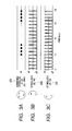
- FIGS. 3A, 3B, and 3C are diagrams illustrating specimens for visual stimulus used in the first embodiment of the present invention.
- FIG. 4 is a graph showing a relation between the stimulation presentation and the BOLD response in the brain.
- FIGS. 5A, 5B, 5C, 5D, 5E, and 5F are graphs showing a relation between the stimulation presentation and the BOLD response according to the first embodiment of the present invention.
- FIG. 6 is a schematic diagram of an electroencephalography (EEG) apparatus including a visual stimulation presenting apparatus for brain function measurement according to a second embodiment of the present invention.
- EEG electroencephalography
- FIGS. 7A, 7B, 7C, 7D, 7E, and 7F are graphs showing a relation between the stimulation presentation and the brain wave response according to the second embodiment of the present invention.
- FIG. 8 is a schematic diagram of a cerebral cortex used for describing a measurement method according to the second embodiment of the present invention.
- FIGS. 9A, 9B, and 9C are protocol diagrams for presenting a visual stimulus to a subject employed in a magnetic resonance imaging apparatus for measuring a brain function according to a conventional example.
- An exemplary embodiment of the present invention relates to a brain function measuring apparatus and a brain function measuring method for measuring a brain function of a subject by presenting a stimulus to the subject through an application of the present invention.
- the embodiment of the present invention provides a stimulation presenting unit configured to present multiple stimulations as the stimulus to be presented to the subject.
- the embodiment further provides a brain function measuring unit configured to measure a brain function activity of the subject responding to the multiple stimulations, and a control unit configured to control the overall brain function measuring apparatus including the stimulation presenting unit and the brain function measuring unit. From multiple stimulations each having a different frequency component and having no cognitive meaning alone, a combined stimulation having a difference frequency between the different frequencies and having a cognitive meaning is generated at regular intervals for measurement, and a higher-order brain function activity responding to this combined stimulation is measured separately from a lower-order brain function activity.
- information having a higher-order cognitive meaning is superimposed when combining the multiple stimulations having different frequencies from each other and the information is modulated with a difference frequency between the different frequencies (beat frequency) so that the resultant information can be detected.
- beat frequency a difference frequency between the different frequencies
- a brain function activity in a higher-order visual area can be extracted separately from a brain function activity in a lower-order visual area by using multiple stimuli of simpler forms.
- is generated from the two stimulations having the different frequency components of Xi and Xj. If information having a higher-order cognitive meaning is superimposed on this combined stimulation, the information is modulated with the difference frequency
- a component of the higher-order brain cognitive function activity generated by the presentation of the combined stimulation can be detected alone without being affected by a measurement result of the lower-order brain function activity, i.e., stimulations modulated with the frequencies Xi and Xj, respectively.
- the stimulations to be presented can include at least one of a visual stimulation, an auditory stimulation, a haptic stimulation, an olfactory stimulation, a gustatory stimulation, and combinations thereof.
- the brain function activity generated by a combination of multimodal stimulations can be measured by measuring a cerebral activity having the frequency component of
- An apparatus for measuring the cerebral activity can be at least one of a functional magnetic resonance imaging apparatus, a magnetoencephalograph, an electroencephalography, a near-infrared spectroscopy brain function measuring apparatus, a positron emission tomography apparatus, and combinations thereof.
- a functional magnetic resonance imaging apparatus e.g., a magnetoencephalograph
- an electroencephalography e.g., an electroencephalography
- a near-infrared spectroscopy brain function measuring apparatus e.g., positron emission tomography apparatus
- positron emission tomography apparatus positron emission tomography apparatus
- a first embodiment of the present invention relates to an example of implementing the brain function measuring apparatus and the brain function measuring method by providing, in a functional magnetic resonance imaging (fMRI) apparatus, an apparatus that can present two visual stimuli to a subject as the multiple stimulations to the subject when measuring a brain function.
- fMRI functional magnetic resonance imaging
- a functional magnetic resonance imaging (fMRI) apparatus is preferred in this embodiment because the functional magnetic resonance imaging (fMRI) apparatus can obtain an image of an active site in a brain accompanied by an onset of a brain function with high sensitivity and spatial resolution.
- FIG. 1 illustrates a configuration example according to the first embodiment in which a visual stimulus presenting apparatus for brain function measurement, configured to present a specimen for visual stimulation to a subject in a selective manner, is provided in a functional magnetic resonance imaging apparatus configured to measure a brain function of a subject.
- a subject 101 lies down on a bed 102 provided in an MRI apparatus 100, which is then disposed in a cylindrical measurement unit (bore) 105 including a gradient magnetic field coil 103 and a superconducting magnet 104.
- a projector (stimulation presenting unit) 106 for presenting a visual stimulus to the subject 101 is provided outside the bore 105 in a direction of the feet of the subject 101.
- a picture or image stimulus is projected from the projector 106 onto a screen 107 that is located in front of eyes of the subject 101 in the bore 105.
- a coil (brain function measuring unit) 108 for detecting an MR signal is installed on the backside of the head of the subject 101, which detects an electromagnetic signal generated by a change of a cerebral blood flow accompanied by a neural activity of the subject 101.
- the coil 108 to be used is a surface type radio frequency (RF) coil.
- All these components are installed in a magnetically shielded room 109.
- the picture or image projected from the projector 106 is controlled by a computer (control unit, not shown) configured to control the overall apparatus, which is set outside the magnetically shielded room 109.
- the projector 106 can alternatively be installed outside the magnetically shielded room 109 by providing a window for transmitting the projection picture or image on the magnetically shielded room 109.
- a visual stimulus A 201 illustrated in FIG. 2A , a visual stimulus B 202 illustrated in FIG. 2B , and a combined stimulus A+B 203 illustrated in FIG. 2C which can be obtained by presenting the visual stimulus A 201 and the visual stimulus B 202 to the subject 101 in a simultaneous manner, are presented to the subject 101 as the stimulations.
- the visual stimulus A 201 and the visual stimulus B 202 are figures that has no cognitive meaning when presented alone, and positions of the visual stimulus A 201 and the visual stimulus B 202 to be presented are adjusted, respectively, to represent a figure such as a face of a human being when presented simultaneously as the combined stimulus A+B 203.
- These stimuli are presented on the screen 107 provided in front of eyes of the subject 101 via the projector 106 while being controlled by the computer.
- the visual stimulus A 201 is presented to the subject 101 while blinking (ON/OFF) with the frequency Xi [Hz] as illustrated in FIG. 3C .
- an ON/OFF time ratio of the blinking is set to 2:8 for simplicity, other values can also be used.
- the visual stimulus B 202 is presented to the subject 101 while blinking (ON/OFF) with the frequency Xj [Hz] as illustrated in FIG. 3B .
- the ON/OFF time ratio of the blinking is set to 2:8, where Xi ⁇ Xj and
- 0.1 ⁇ Xi.
- a presentation of the visual stimulus B 202 is started.
- the visual stimulus A 201 and the visual stimulus B 202 are presented to the subject 101 in a simultaneous manner as the combined stimulus A+B 203 with a predetermined period. That is, although the visual stimulus A 201 and the visual stimulus B 202 are initially presented to the subject 101 while blinking in an alternate manner, since Xi ⁇ Xj, the combined stimulus A+B 203 becomes presented to the subject 101 with a predetermined period at a frequency as illustrated in FIG. 3A .
- This frequency is a difference frequency
- the combined stimulus A+B 203 becomes presented to the subject 101 for every 1/
- FIGS. 4 and 5A to 5F A result of measuring the cerebral activity of the subject 101 by the fMRI method when the visual stimulus A 201, the visual stimulus B 202, and the combined stimulus A+B 203 are presented to the subject 101 is shown in FIGS. 4 and 5A to 5F .
- FIG. 4 is a graph showing a temporal change of the cerebral activity response, which is called a blood oxygenation level dependence (BOLD) signal used in the fMRI measurement when a pulsed visual stimulation is presented to the subject 101.
- BOLD blood oxygenation level dependence
- a nerve in the brain responds to the stimulation, and thus a smooth brain response signal such as the BOLD signal shown in FIG. 4 is obtained.
- This smooth response is generally called an fMRI signal (cerebral activity response) to a stimulation.
- an fMRI signal (BOLD signal to the visual stimulus A 201) is obtained as a waveform shown in FIG. 5E due to a temporal superposition of the signal.
- the visual stimulus A 201 and the visual stimulus B 202 are stimuli having no cognitive meaning as described above, and hence a portion of the brain responding to these stimulations is mainly the primary visual cortex V1.
- the BOLD signals obtained by the visual stimulus A 201 and the visual stimulus B 202 have a time difference of about 0.5 seconds, when the primary visual cortex V1 is measured by the fMRI apparatus, both signals are detected in a state in which they are virtually overlapped without being separated.
- the subject 101 recognizes this stimulus as a "face”, and at this time, a response of the brain is generated at the fusiform face area (FFA) in the brain.
- the fMRI signal caused by this neural activity becomes a waveform shown in FIG. 5A , which oscillates at the frequency of 0.09 Hz.
- a higher-order visual cognitive signal can be detected in a separate manner without being affected by a lower-order visual cognitive brain signal generated as a primary vision.
- the combined stimulus A+B 203 which oscillates at the frequency of
- fMRI functional magnetic resonance imaging
- PET positron emission tomography
- the brain function measuring apparatus and the brain function measuring method are implemented by providing, in an electroencephalography (EEG) apparatus, an apparatus that can present two visual stimuli to a subject as multiple stimulations to be presented to the subject when measuring a brain function.
- EEG electroencephalography
- an electrical signal generated by a neural activity in the brain accompanied by an onset of a brain function can be measured with high sensitivity and high temporal accuracy.
- FIG. 6 is a diagram illustrating a configuration example in which a visual stimulation presenting apparatus for brain function measurement configured to present a specimen for visual stimulus to a subject in a selective manner is provided in a brain function measuring apparatus for measuring a brain function of a subject according to the second embodiment.
- a subject 600 wears an electroencephalography apparatus 601 on the head, and in this state, a visual stimulus 602 is presented to the subject 600.
- the visual stimulus 602 can be presented to the subject 600 by projecting a projector image or picture on a screen, in the same manner as in the first embodiment, or by using a CRT or the like (not shown).
- an electrical signal generated by a neural activity in the brain of the subject 600 is detected by the electroencephalography apparatus 601.
- the detected electrical signal is amplified by an amplifier 603, and only a predetermined frequency signal is extracted by a signal processor 604 from the amplified electrical signal.
- the extracted frequency signal is then displayed on a signal display apparatus.
- FIGS. 7A to 7F A measurement result obtained by the EEG apparatus when the same stimulations as used in the first embodiment are used as the visual stimulus to be presented to the subject 600 is shown in FIGS. 7A to 7F .
- an EEG signal is obtained as a waveform shown in FIG. 7E . Since the EEG signal is obtained by directly detecting the electrical signal generated by the neural activity in the brain, there is no time delay unlike the BOLD signal used in the fMRI measurement. When a pulsed stimulation is presented, the EEG signal is obtained as a pulsed response as shown in FIG. 7E .
- the EEG signal is obtained as a waveform shown in FIG. 7C .
- the visual stimulus A 201 and the visual stimulus B 202 can be stimulations having no cognitive meaning as described above, and hence a portion of the brain responding to these stimulations is mainly the primary visual cortex V1.
- the subject 600 Since the combined stimulus A+B 203 represents a figure of "face” having a cognitive meaning, the subject 600 recognizes this stimulation as a "face”, and at this time, a response of the brain is generated at the fusiform face area (FFA) in the brain.
- the EEG signal caused by this neural activity becomes a waveform shown in FIG. 7A , which is obtained for every 1.1 seconds (frequency of 0.09 Hz).
- a response to the combined stimulus A+B 203 that has a cognitive meaning is generated in the brain (FFA) at the frequency of 0.09 Hz.
- a higher-order visual cognitive signal can be detected in a separate manner without being affected by a lower-order visual cognitive brain signal generated as a primary vision.
- the EEG measurement is inferior to the fMRI measurement in terms of the spatial resolution.
- multiple electrodes can be used on the head of the subject in the EEG measurement, and the signals can be detected with a focus on electrical signals generated by neural activities near the electrodes.
- FIG. 8 is a schematic diagram of a cerebral cortex 800 of the left side of the brain of a human being.
- the primary visual cortex (V1) 801 is located on the posterior side of the cerebral cortex 800, and the fusiform face area (FFA) is located near an area 802 that is called the FG on the temporal area.
- V1 The primary visual cortex
- FFA fusiform face area
- the signals can be detected with higher accuracy by disposing the EEG electrodes on the scalp near, A: primary visual cortex V1, B: primary visual cortex V1, and A+B: FG area, respectively.
- the same measurement can be performed by using a magnetoencephalograph (MEG).
- MEG magnetoencephalograph
- the subject wears a magnetoencephalograph apparatus (not shown) on the head instead of the electroencephalography apparatus 601 for the EEG measurement.
- a measurement result can be obtained as the virtually same signal as obtained in the second embodiment using the EEG apparatus.
- signals respectively obtained from a detecting element located on the scalp near the primary visual cortex V1 of the cerebral cortex and a detecting element located on the scalp near the FG area are analyzed. With this operation, electromagnetic signals generated in the brain by the visual stimulus A 201, the visual stimulus B 202, and the combined stimulus A+B 203 can be separated.
- a similar measurement can be performed using a functional near-infrared spectroscopy (fNIRS) apparatus.
- a signal detector (not shown) is worn by the subject on the head for measurement in the same manner as the EEG according to the second embodiment.
- the detector can be disposed in contact with the scalp near the primary visual cortex V1 and the FG area in the same manner as the EEG.
- the fNIRS detects a BOLD signal, a relation between a presented stimulation and an obtained detection signal becomes similar to the waveform obtained using the fMRI in the first embodiment ( FIGS. 5A to 5F ).
- the stimulation to be used is not limited to the visual stimulation.
- a similar measurement can be performed by using any one of the auditory stimulation, the haptic stimulation, the olfactory stimulation, and the gustatory stimulation.
- a similar measurement can be performed by using a combination of different types of stimulations (multimodal stimulation), such as a combination of the visual stimulation and the auditory stimulation or a combination of the visual stimulation and the haptic stimulation.
- multimodal stimulation if stimulations forming the multimodal stimulation are modulated with different frequencies from each other, the lower-order brain function activities generated by the respective stimulations and the higher-order brain function activity generated by a combination of the stimulations can be measured separately from each other.
- a brain function activity of a subject is measured using a brain function measuring unit by presenting multiple stimulations, which are adjusted to have no cognitive meaning when presented in a separate manner and to have a cognitive meaning when presented simultaneously as a combined stimulation, to the subject as the combined stimulation at regular intervals with a control of a control unit, thus measuring a higher cognitive brain activity responding to the combined stimulation separately from a lower cognitive brain activity.
Landscapes
- Health & Medical Sciences (AREA)
- Life Sciences & Earth Sciences (AREA)
- Physics & Mathematics (AREA)
- Molecular Biology (AREA)
- Animal Behavior & Ethology (AREA)
- Nuclear Medicine, Radiotherapy & Molecular Imaging (AREA)
- Biophysics (AREA)
- Pathology (AREA)
- Engineering & Computer Science (AREA)
- Biomedical Technology (AREA)
- Heart & Thoracic Surgery (AREA)
- Medical Informatics (AREA)
- Veterinary Medicine (AREA)
- Surgery (AREA)
- Public Health (AREA)
- General Health & Medical Sciences (AREA)
- Radiology & Medical Imaging (AREA)
- High Energy & Nuclear Physics (AREA)
- Psychiatry (AREA)
- Psychology (AREA)
- Magnetic Resonance Imaging Apparatus (AREA)
- Measurement And Recording Of Electrical Phenomena And Electrical Characteristics Of The Living Body (AREA)
- Nuclear Medicine (AREA)
- Measurement Of The Respiration, Hearing Ability, Form, And Blood Characteristics Of Living Organisms (AREA)
Abstract
Description
- The present invention relates to a brain function measuring apparatus and a brain function measuring method, and more particularly, to a brain function measuring apparatus and a brain function measuring method for detecting response and function of a brain when a sensory stimulus is presented to a subject.
- In fields of medical science, biology, and psychology, in order to study a brain function of a subject, an apparatus is employed, which presents various stimuli such as visual, haptic, and auditory stimuli to a subject and measures a cerebral activity caused by the stimulations. As a representative apparatus for measuring the brain function, for example, an electroencephalography (EEG), a magnetoencephalograph (MEG), a functional magnetic resonance imaging (fMRI) apparatus, a functional near-infrared spectroscopy (fNIRS) apparatus, and a positron emission tomography (PET) apparatus have been known.
- These apparatus measure an amount of the cerebral activity by detecting a physical amount such as a change of an electromagnetic wave (EEG and MEG) or a change of a blood flow rate (fMRI, fNIRS, and PET) generated by an activity of a nerve in an area of the brain in response to the stimulation presented to the human being. However, since these types of physical amounts generally have weak signals, they are significantly affected by various events such as a noise or a change of a cerebral activity that are not related to the presented stimulus.
- Therefore, a measurement method is often used in which the stimulus to be presented to the subject is devised to extract the cerebral activity corresponding to the presented stimulus. For example, a method called a "block design" is often used in a brain function measurement using the fMRI method.
- In the block design method, a state called a "rest block" in which the sensory stimuli is not presented to the subject and a state called a "task block" in which the sensory stimuli is presented to the subject are repeated in an alternate manner. Two types of images are then acquired, which include a functional brain imaging obtained in the rest period (i.e., an image in the state in which the sensory stimulus is not presented to the subject) and a functional brain imaging obtained in the task period (i.e., an image in the state in which the sensory stimulus is presented to the subject). Through comparison between the two types of images acquired in the above-mentioned manner, a functional brain imaging, on which a cerebral activity status in the state in which the sensory stimulation is presented to the brain is reflected, can be finally obtained.
- According to "a course "Science of Sense and Perception" 1, Visual Sense I, Edited by Keizo Shinomori, Asakura Publishing Co., Ltd., ISBN 978-4-254-10631-2", it has been disclosed that, after the information is delivered to the brain from a sensory organ such as eyes and ears via a nerve system, a process of the sensory information in the brain is roughly divided into an initial stage of information processing (lower cognitive brain activity) and a later stage of information processing (higher cognitive brain activity).
- To describe this with an example of the visual sense, the visual information is transformed from an optical signal into an electrical signal in a retina and delivered to an area of the cerebral cortex for processing an initial stage of the visual information, which is called a "primary visual cortex" (hereinafter, abbreviated as "V1"), via the nerve system. In the V1 area, local visual characteristics such as a slope of a line, a motion, a depth, and a color are detected from among image information included in the visual information. This process is called a "lower-order visual processing".
- The information processed in the V1 is then delivered to a portion for performing a process for finally performing a "visual perception", which is called a "higher-order visual processing".
- The "higher-order visual processing" is roughly divided into two processes.
- One of the processes is for processing information on the motion or the depth by obtaining information that is required to perform a mutual action between a surrounding environment or object and the human being. These pieces of information are processed in the cerebral cortex called a "dorsal stream", and processed in an area assigned with a name such as medial temporal (MT), medial superior temporal (MST), and intraparietal areas (IPA).
- The other of the processes is a function of recognizing an object or a person by collating information on the object or the person with a memory, which requires recognitions of color and detailed form including a three-dimensional structure. These pieces of information are processed in the cerebral cortex called a "ventral stream", and processed in an area assigned with a name such as fourth visual cortex (V4) and inferotemporal (IT).
- A situation is assumed in which a lower-order processing function and a higher-order processing function of the brain on the visual sense are measured in a separate manner in the block design method described above.
- For example, when an image of a face is presented to a subject, a lower-order visual cortex such as the V1 area and an area called a "fusiform gyrus (FG)" included in the IT area that uniquely responds to the image of the face from among the higher-order visual information processing, in response to a "task block" of showing the image of the face. In a "rest block" in which nothing is presented, none of the V1 and FG areas shows response. In general, the function of the brain with respect to certain stimulation is determined with a difference between the information obtained in the "task block" and the information obtained in the "rest block".
- However, in this case, the lower-order visual information obtained in the V1 area and the higher-order visual information obtained in the FG area respond to the task in the task block (presentation of the image of the face to the subject) in a virtually simultaneous manner, and hence it is difficult to separately obtain the signals.
- To cope with these problems, regarding a method of detecting a visual brain function by using the fMRI method, Japanese Patent Application Laid-Open No.
2007-190352 FIGS. 9A, 9B and 9C . In this technique, two stimulations having a predetermined stimulation interval (ISI) are grouped as a pair, and this pair is sequentially presented with a constant stimulation period T by changing the stimulation interval (ISI) of the pair. The stimulation interval (ISI) of the pair of stimulations is gradually increased and then gradually decreased so that a temporal change of an activity in each area of the brain can be figured out with such an action as increasing the temporal resolution in an equivalent manner by shifting a timing for presenting the stimulation little by little. As a result, a time difference in the information processing between a fusiform face area (FFA) near the IT area that is supposed to process the information on the face and a visual cortex can be detected. - However, in the conventional technique described above, which can only be applied to the brain function measurement using the fMRI method, the timing for presenting the stimulation is changed by controlling the ISI, and hence a control of the stimulation to be presented becomes complicated.
- Further, an image of a desired timing is obtained only two times in a period in which the ISI is increased and decreased one time from a measurement target area of the brain responding to the periodic stimulation. However, since the fMRI signal is weak, in order to obtain an image with a high S/N ratio, it is necessary to take multiple images and to perform an image processing such as averaging the obtained images.
- In addition, if there are multiple desired timings, sampling of the above-mentioned processing needs to be performed as many times as needed, which may cause an increase of the imaging time or the data size.
- In view of the above-mentioned problems, the present invention is directed to a simply configured brain function measuring apparatus and a brain function measuring method that enable a measurement of a higher cognitive brain activity induced by a stimulation separately from a lower cognitive brain activity, when detecting a brain function by presenting the stimulation to a subject.
- According to an exemplary embodiment of the present invention, there is provided a brain function measuring apparatus, including: a stimulation presenting unit configured to present multiple stimuli to a subject; and a brain function measuring unit configured to measure a brain function activity of the subject responding to the multiple stimulations. The multiple stimuli are adjusted to have no cognitive meaning when presented in a separate manner and to have a cognitive meaning when presented simultaneously as a combined stimulus. The stimulation presenting unit is configured to present the combined stimulus at regular intervals.
- Further, according to an exemplary embodiment of the present invention, there is provided a brain function measuring method, including: presenting multiple stimulations to a subject; and measuring a brain function activity of the subject responding to the multiple stimulations. The multiple stimuli are adjusted to have no cognitive meaning when presented in a separate manner and to have a cognitive meaning when presented simultaneously as a combined stimulus. This presenting procedure includes presenting the combined stimulus at regular intervals.
- According to the present invention, the brain function measuring apparatus and the brain function measuring method can be achieved which enable a measurement of a higher-order brain function activity induced by a stimulation separately from a lower-order brain function activity with a simple configuration when detecting a brain function activity by presenting the stimuli to a subject.
- Further features of the present invention will become apparent from the following description of exemplary embodiments with reference to the attached drawings.
-
FIG. 1 is a cross-sectional view of a brain function measuring apparatus (functional magnetic resonance imaging (fMRI) apparatus) including a visual stimulation presenting apparatus for brain function measurement according to a first embodiment of the present invention. -
FIGS. 2A, 2B, and 2C are diagrams illustrating image stimuli presented by the visual stimulation presenting apparatus for brain function measurement according to the first embodiment of the present invention. -
FIGS. 3A, 3B, and 3C are diagrams illustrating specimens for visual stimulus used in the first embodiment of the present invention. -
FIG. 4 is a graph showing a relation between the stimulation presentation and the BOLD response in the brain. -
FIGS. 5A, 5B, 5C, 5D, 5E, and 5F are graphs showing a relation between the stimulation presentation and the BOLD response according to the first embodiment of the present invention. -
FIG. 6 is a schematic diagram of an electroencephalography (EEG) apparatus including a visual stimulation presenting apparatus for brain function measurement according to a second embodiment of the present invention. -
FIGS. 7A, 7B, 7C, 7D, 7E, and 7F are graphs showing a relation between the stimulation presentation and the brain wave response according to the second embodiment of the present invention. -
FIG. 8 is a schematic diagram of a cerebral cortex used for describing a measurement method according to the second embodiment of the present invention. -
FIGS. 9A, 9B, and 9C are protocol diagrams for presenting a visual stimulus to a subject employed in a magnetic resonance imaging apparatus for measuring a brain function according to a conventional example. - An exemplary embodiment of the present invention relates to a brain function measuring apparatus and a brain function measuring method for measuring a brain function of a subject by presenting a stimulus to the subject through an application of the present invention.
- The embodiment of the present invention provides a stimulation presenting unit configured to present multiple stimulations as the stimulus to be presented to the subject. The embodiment further provides a brain function measuring unit configured to measure a brain function activity of the subject responding to the multiple stimulations, and a control unit configured to control the overall brain function measuring apparatus including the stimulation presenting unit and the brain function measuring unit. From multiple stimulations each having a different frequency component and having no cognitive meaning alone, a combined stimulation having a difference frequency between the different frequencies and having a cognitive meaning is generated at regular intervals for measurement, and a higher-order brain function activity responding to this combined stimulation is measured separately from a lower-order brain function activity.
- That is, information having a higher-order cognitive meaning is superimposed when combining the multiple stimulations having different frequencies from each other and the information is modulated with a difference frequency between the different frequencies (beat frequency) so that the resultant information can be detected. With this configuration, by extracting and detecting a brain function activity responding to the beat frequency, a higher-order brain cognitive function activity can be detected without being affected by a measurement result of a lower-order brain function activity.
- According to the above-mentioned configuration, a brain function activity in a higher-order visual area can be extracted separately from a brain function activity in a lower-order visual area by using multiple stimuli of simpler forms.
- In the brain function measuring method and the brain function measuring apparatus according to this embodiment configured in the above-mentioned manner, specifically, a configuration can be adopted which has a function of detecting, with respect to arbitrary two stimulations modulated with different frequencies Xi [Hz] and Xj [Hz], respectively, from multiple stimulations to be presented to a subject (where i=1, 2, 3, ..., N, j=1, 2, 3, ..., N, i≠j, and N is the number of stimulations), a brain activity having a frequency component of Xi [Hz], Xj [Hz], and |Xi-Xj| [Hz].
- With this configuration, a combined stimulation having the difference frequency |Xi-Xj| is generated from the two stimulations having the different frequency components of Xi and Xj. If information having a higher-order cognitive meaning is superimposed on this combined stimulation, the information is modulated with the difference frequency |Xi-Xj| (beat frequency), and therefore, a brain function activity corresponding to the beat frequency can be extracted and detected.
- As a result, a component of the higher-order brain cognitive function activity generated by the presentation of the combined stimulation can be detected alone without being affected by a measurement result of the lower-order brain function activity, i.e., stimulations modulated with the frequencies Xi and Xj, respectively.
- The stimulations to be presented can include at least one of a visual stimulation, an auditory stimulation, a haptic stimulation, an olfactory stimulation, a gustatory stimulation, and combinations thereof. With this configuration, the brain function activity generated by a combination of multimodal stimulations can be measured by measuring a cerebral activity having the frequency component of |Xi-Xj| described above.
- An apparatus for measuring the cerebral activity can be at least one of a functional magnetic resonance imaging apparatus, a magnetoencephalograph, an electroencephalography, a near-infrared spectroscopy brain function measuring apparatus, a positron emission tomography apparatus, and combinations thereof. With this configuration, the higher-order cerebral activity with respect to the presented stimulation, which has conventionally been measured mainly by the fMRI apparatus, can be measured by other measuring apparatus and methods as described above.
- (Embodiments)
- Specific embodiments of the present invention are described below.
- (First Embodiment)
- A first embodiment of the present invention relates to an example of implementing the brain function measuring apparatus and the brain function measuring method by providing, in a functional magnetic resonance imaging (fMRI) apparatus, an apparatus that can present two visual stimuli to a subject as the multiple stimulations to the subject when measuring a brain function.
- A functional magnetic resonance imaging (fMRI) apparatus is preferred in this embodiment because the functional magnetic resonance imaging (fMRI) apparatus can obtain an image of an active site in a brain accompanied by an onset of a brain function with high sensitivity and spatial resolution.
-
FIG. 1 illustrates a configuration example according to the first embodiment in which a visual stimulus presenting apparatus for brain function measurement, configured to present a specimen for visual stimulation to a subject in a selective manner, is provided in a functional magnetic resonance imaging apparatus configured to measure a brain function of a subject. - In the first embodiment, as illustrated in
FIG. 1 , a subject 101 lies down on abed 102 provided in anMRI apparatus 100, which is then disposed in a cylindrical measurement unit (bore) 105 including a gradientmagnetic field coil 103 and asuperconducting magnet 104. A projector (stimulation presenting unit) 106 for presenting a visual stimulus to the subject 101 is provided outside thebore 105 in a direction of the feet of the subject 101. A picture or image stimulus is projected from theprojector 106 onto ascreen 107 that is located in front of eyes of the subject 101 in thebore 105. A coil (brain function measuring unit) 108 for detecting an MR signal is installed on the backside of the head of the subject 101, which detects an electromagnetic signal generated by a change of a cerebral blood flow accompanied by a neural activity of the subject 101. In this case, in order to secure a view in front of the subject 101 and to perform a highly sensitive brain function measurement in a visual cortex, i.e., the back of the head of the subject 101, thecoil 108 to be used is a surface type radio frequency (RF) coil. - All these components are installed in a magnetically shielded
room 109. The picture or image projected from theprojector 106 is controlled by a computer (control unit, not shown) configured to control the overall apparatus, which is set outside the magnetically shieldedroom 109. - The
projector 106 can alternatively be installed outside the magnetically shieldedroom 109 by providing a window for transmitting the projection picture or image on the magnetically shieldedroom 109. - In the first embodiment, for example, a
visual stimulus A 201 illustrated inFIG. 2A , avisual stimulus B 202 illustrated inFIG. 2B , and a combined stimulus A+B 203 illustrated inFIG. 2C , which can be obtained by presenting thevisual stimulus A 201 and thevisual stimulus B 202 to the subject 101 in a simultaneous manner, are presented to the subject 101 as the stimulations. Thevisual stimulus A 201 and thevisual stimulus B 202 are figures that has no cognitive meaning when presented alone, and positions of thevisual stimulus A 201 and thevisual stimulus B 202 to be presented are adjusted, respectively, to represent a figure such as a face of a human being when presented simultaneously as the combined stimulus A+B 203. - These stimuli are presented on the
screen 107 provided in front of eyes of the subject 101 via theprojector 106 while being controlled by the computer. - The
visual stimulus A 201 is presented to the subject 101 while blinking (ON/OFF) with the frequency Xi [Hz] as illustrated inFIG. 3C . Although an ON/OFF time ratio of the blinking is set to 2:8 for simplicity, other values can also be used. - Similarly, the
visual stimulus B 202 is presented to the subject 101 while blinking (ON/OFF) with the frequency Xj [Hz] as illustrated inFIG. 3B . In this case, the ON/OFF time ratio of the blinking is set to 2:8, where Xi≠Xj and |Xi-Xj|=0.1×Xi. In half a period (i.e., 1/(2×Xi) seconds) after starting a presentation of thevisual stimulus A 201, a presentation of thevisual stimulus B 202 is started. - In this embodiment, by presenting the stimuli to the subject 101 under the above-mentioned condition, the
visual stimulus A 201 and thevisual stimulus B 202 are presented to the subject 101 in a simultaneous manner as the combined stimulus A+B 203 with a predetermined period. That is, although thevisual stimulus A 201 and thevisual stimulus B 202 are initially presented to the subject 101 while blinking in an alternate manner, since Xi≠Xj, the combined stimulus A+B 203 becomes presented to the subject 101 with a predetermined period at a frequency as illustrated inFIG. 3A . This frequency is a difference frequency |Xi-Xj| [Hz] of the blinking frequency Xi of thevisual stimulus A 201 and the blinking frequency Xj of thevisual stimulus B 202. Therefore, by displaying thevisual stimulus A 201 at the frequency Xi [Hz] and thevisual stimulus B 202 at the frequency Xj [Hz] while blinking, the combined stimulus A+B 203 becomes presented to the subject 101 for every 1/|Xi-Xj| seconds. - This means that, by presenting the
visual stimulus A 201 and thevisual stimulus B 202, which have no cognitive meaning to the human being, to the subject 101 under the above-mentioned condition, the combined stimulus A+B 203 that cognitively means a "face" to the human being becomes presented to the subject 101 for every 1/|Xi-Xj| seconds. - A result of measuring the cerebral activity of the subject 101 by the fMRI method when the
visual stimulus A 201, thevisual stimulus B 202, and the combined stimulus A+B 203 are presented to the subject 101 is shown inFIGS. 4 and5A to 5F . -
FIG. 4 is a graph showing a temporal change of the cerebral activity response, which is called a blood oxygenation level dependence (BOLD) signal used in the fMRI measurement when a pulsed visual stimulation is presented to the subject 101. When the pulsed visual stimulation is presented a single time, a nerve in the brain responds to the stimulation, and thus a smooth brain response signal such as the BOLD signal shown inFIG. 4 is obtained. This smooth response is generally called an fMRI signal (cerebral activity response) to a stimulation. - When the
visual stimulus A 201 is repeatedly presented with a width of 0.2 seconds and Xi=1 Hz (1/Xi=1 second interval) as shown inFIG. 5F , an fMRI signal (BOLD signal to the visual stimulus A 201) is obtained as a waveform shown inFIG. 5E due to a temporal superposition of the signal. Further, when thevisual stimulus B 202 is repeatedly presented with a width of 0.2 seconds and Xj≈0.91 Hz (1/Xj=1.1 second interval) with a delay of 0.5 seconds with respect to thevisual stimulus A 201 as shown inFIG. 5D , the fMRI signal is obtained as a waveform shown inFIG. 5C . Thevisual stimulus A 201 and thevisual stimulus B 202 are stimuli having no cognitive meaning as described above, and hence a portion of the brain responding to these stimulations is mainly the primary visual cortex V1. - Since the BOLD signals obtained by the
visual stimulus A 201 and thevisual stimulus B 202 have a time difference of about 0.5 seconds, when the primary visual cortex V1 is measured by the fMRI apparatus, both signals are detected in a state in which they are virtually overlapped without being separated. - On the other hand, the
visual stimulus A 201 and thevisual stimulus B 202 are modulated with frequencies Xi=1 Hz and Xj≈0.91 Hz, respectively, and hence a shift of the frequency is accumulated so that the combined stimulus A+B 203 is presented to the subject 101 as a beat signal with a period of |Xi-Xj|≈0.09 Hz (FIG. 5B ). - Since the combined stimulus A+
B 203 represents a figure of "face" having a cognitive meaning, the subject 101 recognizes this stimulus as a "face", and at this time, a response of the brain is generated at the fusiform face area (FFA) in the brain. The fMRI signal caused by this neural activity becomes a waveform shown inFIG. 5A , which oscillates at the frequency of 0.09 Hz. - In this manner, by presenting the
visual stimulus A 201 having the frequency Xi=1 Hz and thevisual stimulus B 202 having the frequency Xj=0.91 Hz to the subject 101 in a simultaneous manner, a response to the combined stimulus A+B 203 that has a cognitive meaning is generated in the brain (FFA) at the frequency of 0.09 Hz. - Through detection of a signal of this frequency, a higher-order visual cognitive signal can be detected in a separate manner without being affected by a lower-order visual cognitive brain signal generated as a primary vision.
- It has been known that, when a pulsed sensory stimulus is presented to a subject in a repeated manner, an intensity of a response in the brain is decreased gradually due to an adaptation effect. In this case, a magnitude of the fMRI signal is decreased accordingly. In the cases of the
visual stimulus A 201 and thevisual stimulus B 202 described above, also, since the magnitude of the fMRI signal are repeatedly presented to the subject, they may be gradually decreased. - However, the combined stimulus A+
B 203, which oscillates at the frequency of |Xi-Xj| Hz, can adjust the frequency |Xi-Xj| to the extent that a decrease of a signal level due to the adaptation effect can be reduced enough, and hence the higher-order visual cognitive signal can be separately detected at this frequency. - Although the functional magnetic resonance imaging (fMRI) apparatus is employed in this embodiment, a similar measurement can also be performed by using a positron emission tomography (PET). In this case, the subject is placed in a PET apparatus instead of the fMRI apparatus to perform the same measurement (not shown).
- (Second Embodiment)
- In a second embodiment of the present invention, the brain function measuring apparatus and the brain function measuring method are implemented by providing, in an electroencephalography (EEG) apparatus, an apparatus that can present two visual stimuli to a subject as multiple stimulations to be presented to the subject when measuring a brain function. In the case of using the electroencephalography apparatus, an electrical signal generated by a neural activity in the brain accompanied by an onset of a brain function can be measured with high sensitivity and high temporal accuracy.
-
FIG. 6 is a diagram illustrating a configuration example in which a visual stimulation presenting apparatus for brain function measurement configured to present a specimen for visual stimulus to a subject in a selective manner is provided in a brain function measuring apparatus for measuring a brain function of a subject according to the second embodiment. - In this embodiment, as illustrated in
FIG. 6 , a subject 600 wears anelectroencephalography apparatus 601 on the head, and in this state, avisual stimulus 602 is presented to the subject 600. Thevisual stimulus 602 can be presented to the subject 600 by projecting a projector image or picture on a screen, in the same manner as in the first embodiment, or by using a CRT or the like (not shown). - Through the presentation of the
visual stimulus 602, an electrical signal generated by a neural activity in the brain of the subject 600 is detected by theelectroencephalography apparatus 601. The detected electrical signal is amplified by anamplifier 603, and only a predetermined frequency signal is extracted by asignal processor 604 from the amplified electrical signal. The extracted frequency signal is then displayed on a signal display apparatus. - A measurement result obtained by the EEG apparatus when the same stimulations as used in the first embodiment are used as the visual stimulus to be presented to the subject 600 is shown in
FIGS. 7A to 7F . - When the
visual stimulus A 201 is repeatedly presented with a width of 0.2 seconds and Xi=1 Hz (1/Xi=1 second interval) as shown inFIG. 7F , an EEG signal is obtained as a waveform shown inFIG. 7E . Since the EEG signal is obtained by directly detecting the electrical signal generated by the neural activity in the brain, there is no time delay unlike the BOLD signal used in the fMRI measurement. When a pulsed stimulation is presented, the EEG signal is obtained as a pulsed response as shown inFIG. 7E . - Further, when the
visual stimulus B 202 is repeatedly presented with a width of 0.2 seconds and Xj≈0.91 Hz (1/Xj=1.1 second interval) with a delay of 0.5 seconds with respect to thevisual stimulus A 201 as shown inFIG. 7D , the EEG signal is obtained as a waveform shown inFIG. 7C . - The
visual stimulus A 201 and thevisual stimulus B 202 can be stimulations having no cognitive meaning as described above, and hence a portion of the brain responding to these stimulations is mainly the primary visual cortex V1. - On the other hand, since the
visual stimulus A 201 and thevisual stimulus B 202 are modulated with frequencies Xi=1 Hz and Xj≈0.91 Hz, respectively, a shift of the frequency is accumulated so that the combined stimulus A+B 203 is presented to the subject 600 as a beat signal with a period of |Xi-Xj|≈0.09 Hz (FIG. 7B ). - Since the combined stimulus A+
B 203 represents a figure of "face" having a cognitive meaning, the subject 600 recognizes this stimulation as a "face", and at this time, a response of the brain is generated at the fusiform face area (FFA) in the brain. The EEG signal caused by this neural activity becomes a waveform shown inFIG. 7A , which is obtained for every 1.1 seconds (frequency of 0.09 Hz). In this manner, by presenting thevisual stimulus A 201 having the frequency Xi=1 Hz and thevisual stimulus B 202 having the frequency Xj=0.91 Hz to the subject 600 in a simultaneous manner, a response to the combined stimulus A+B 203 that has a cognitive meaning is generated in the brain (FFA) at the frequency of 0.09 Hz. - Through detection of a signal of this frequency, a higher-order visual cognitive signal can be detected in a separate manner without being affected by a lower-order visual cognitive brain signal generated as a primary vision.
- It is said that the EEG measurement is inferior to the fMRI measurement in terms of the spatial resolution. However, multiple electrodes can be used on the head of the subject in the EEG measurement, and the signals can be detected with a focus on electrical signals generated by neural activities near the electrodes.
-
FIG. 8 is a schematic diagram of acerebral cortex 800 of the left side of the brain of a human being. The primary visual cortex (V1) 801 is located on the posterior side of thecerebral cortex 800, and the fusiform face area (FFA) is located near anarea 802 that is called the FG on the temporal area. - Therefore, when detecting signals on the
visual stimulus A 201, thevisual stimulus B 202, and the combined stimulus A+B 203, the signals can be detected with higher accuracy by disposing the EEG electrodes on the scalp near, A: primary visual cortex V1, B: primary visual cortex V1, and A+B: FG area, respectively. - Although a case of using the EEG measuring apparatus is described in this embodiment, the same measurement can be performed by using a magnetoencephalograph (MEG). In this case, the subject wears a magnetoencephalograph apparatus (not shown) on the head instead of the
electroencephalography apparatus 601 for the EEG measurement. A measurement result can be obtained as the virtually same signal as obtained in the second embodiment using the EEG apparatus. In this case, among detecting elements in detecting devices of multiple MEG apparatus, signals respectively obtained from a detecting element located on the scalp near the primary visual cortex V1 of the cerebral cortex and a detecting element located on the scalp near the FG area are analyzed. With this operation, electromagnetic signals generated in the brain by thevisual stimulus A 201, thevisual stimulus B 202, and the combined stimulus A+B 203 can be separated. - Further, a similar measurement can be performed using a functional near-infrared spectroscopy (fNIRS) apparatus. When using the fNIRS apparatus, a signal detector (not shown) is worn by the subject on the head for measurement in the same manner as the EEG according to the second embodiment. The detector can be disposed in contact with the scalp near the primary visual cortex V1 and the FG area in the same manner as the EEG. However, since the fNIRS detects a BOLD signal, a relation between a presented stimulation and an obtained detection signal becomes similar to the waveform obtained using the fMRI in the first embodiment (
FIGS. 5A to 5F ). - In the first and second embodiments described above, examples of measuring the lower cognitive brain activity (no cognitive cerebral activity) and the higher cognitive brain activity (cognitive cerebral activity) separately from each other by using multiple visual stimulations are described.
- However, in the brain function measuring apparatus and the brain function measuring method according to the present invention, the stimulation to be used is not limited to the visual stimulation. A similar measurement can be performed by using any one of the auditory stimulation, the haptic stimulation, the olfactory stimulation, and the gustatory stimulation. Further, a similar measurement can be performed by using a combination of different types of stimulations (multimodal stimulation), such as a combination of the visual stimulation and the auditory stimulation or a combination of the visual stimulation and the haptic stimulation. Also in the case of using the multimodal stimulation, if stimulations forming the multimodal stimulation are modulated with different frequencies from each other, the lower-order brain function activities generated by the respective stimulations and the higher-order brain function activity generated by a combination of the stimulations can be measured separately from each other.
- While the present invention has been described with reference to exemplary embodiments, it is to be understood that the invention is not limited to the disclosed exemplary embodiments. The scope of the following claims is to be accorded the broadest interpretation so as to encompass all such modifications and equivalent structures and functions.
A brain function activity of a subject is measured using a brain function measuring unit by presenting multiple stimulations, which are adjusted to have no cognitive meaning when presented in a separate manner and to have a cognitive meaning when presented simultaneously as a combined stimulation, to the subject as the combined stimulation at regular intervals with a control of a control unit, thus measuring a higher cognitive brain activity responding to the combined stimulation separately from a lower cognitive brain activity.
Claims (8)
- A brain function measuring apparatus, comprising:a stimulation presenting unit configured to present multiple stimuli which function as multiple stimulations to a subject; anda brain function measuring unit configured to measure a brain function activity of the subject responding to the multiple stimulations, wherein:the multiple stimulations are adjusted to have no cognitive meaning when presented in a separate manner and to have a cognitive meaning when presented simultaneously as a combined stimulation; andthe stimulation presenting unit is configured to present the combined stimulation at regular intervals.
- The brain function measuring apparatus according to claim 1, wherein:the multiple stimulations are modulated with different frequencies from each other; andthe combined stimulation is configured to have a difference frequency between the different frequencies.
- The brain function measuring apparatus according to claim 1, wherein the multiple stimulations comprise at least one of a visual stimulation, an auditory stimulation, a haptic stimulation, an olfactory stimulation, a gustatory stimulation, and combinations thereof.
- The brain function measuring apparatus according to claim 1, wherein the brain function measuring unit comprises at least one of a functional magnetic resonance imaging apparatus, a magnetoencephalograph, an electroencephalography, a near-infrared spectroscopy brain function measuring apparatus, a positron emission tomography apparatus, and combinations thereof.
- A brain function measuring method, comprising:presenting multiple stimuli which function as multiple stimulations to a subject; andmeasuring a brain function activity of the subject responding to the multiple stimulations, wherein:the multiple stimulations are adjusted to have no cognitive meaning when presented in a separate manner and to have a cognitive meaning when presented simultaneously as a combined stimulation; andthe presenting comprises presenting the combined stimulation at regular intervals.
- The brain function measuring method according to claim 5, wherein:the multiple stimulations are modulated with different frequencies from each other; andthe combined stimulation is configured to have a difference frequency between the different frequencies.
- The brain function measuring method according to claim 5, wherein the multiple stimulations comprise at least one of a visual stimulation, an auditory stimulation, a haptic stimulation, an olfactory stimulation, a gustatory stimulation, and combinations thereof.
- The brain function measuring method according to claim 5, wherein the measuring comprises measuring the brain function activity of the subject by using at least one of a functional magnetic resonance imaging apparatus, a magnetoencephalograph, an electroencephalography, a near-infrared spectroscopy brain function measuring apparatus, a positron emission tomography apparatus, and combinations thereof.
Applications Claiming Priority (1)
| Application Number | Priority Date | Filing Date | Title |
|---|---|---|---|
| JP2011115521A JP2012239789A (en) | 2011-05-24 | 2011-05-24 | Brain function measuring apparatus and method |
Publications (1)
| Publication Number | Publication Date |
|---|---|
| EP2526862A1 true EP2526862A1 (en) | 2012-11-28 |
Family
ID=46147324
Family Applications (1)
| Application Number | Title | Priority Date | Filing Date |
|---|---|---|---|
| EP12168608A Withdrawn EP2526862A1 (en) | 2011-05-24 | 2012-05-21 | Brain function measuring apparatus and brain function measuring method |
Country Status (3)
| Country | Link |
|---|---|
| US (1) | US20120302867A1 (en) |
| EP (1) | EP2526862A1 (en) |
| JP (1) | JP2012239789A (en) |
Cited By (1)
| Publication number | Priority date | Publication date | Assignee | Title |
|---|---|---|---|---|
| CN111588348A (en) * | 2019-02-20 | 2020-08-28 | 株式会社岛津制作所 | Metrics for Cognitive Function |
Families Citing this family (18)
| Publication number | Priority date | Publication date | Assignee | Title |
|---|---|---|---|---|
| ES2776178T3 (en) | 2012-10-24 | 2020-07-29 | Dreamscape Medical Llc | Systems to detect brain-based bio-signals |
| JP2015000100A (en) * | 2013-06-13 | 2015-01-05 | キヤノン株式会社 | Method, program, and recording medium thereof for identifying spatial distribution of territory in sensory area of brain |
| KR20160049273A (en) * | 2014-10-27 | 2016-05-09 | 삼성전자주식회사 | Medical imaging apparatus |
| KR101660332B1 (en) * | 2014-12-30 | 2016-09-29 | 한국과학기술연구원 | Device and method for measuring cognitive fatigue based on tactile stimuli |
| US20180132714A1 (en) * | 2016-11-16 | 2018-05-17 | Infinite Mind, LC | Apparatus and method for measuring brain processing speed |
| CN110520041B (en) * | 2017-04-28 | 2022-07-05 | 麦克赛尔株式会社 | Brain wave data analysis system, information processing terminal, electronic device, and information presentation method for cognitive disorder examination |
| WO2019060298A1 (en) | 2017-09-19 | 2019-03-28 | Neuroenhancement Lab, LLC | Method and apparatus for neuroenhancement |
| US11717686B2 (en) | 2017-12-04 | 2023-08-08 | Neuroenhancement Lab, LLC | Method and apparatus for neuroenhancement to facilitate learning and performance |
| JP7069716B2 (en) | 2017-12-28 | 2022-05-18 | 株式会社リコー | Biological function measurement and analysis system, biological function measurement and analysis program, and biological function measurement and analysis method |
| US12280219B2 (en) | 2017-12-31 | 2025-04-22 | NeuroLight, Inc. | Method and apparatus for neuroenhancement to enhance emotional response |
| US11478603B2 (en) | 2017-12-31 | 2022-10-25 | Neuroenhancement Lab, LLC | Method and apparatus for neuroenhancement to enhance emotional response |
| US11364361B2 (en) | 2018-04-20 | 2022-06-21 | Neuroenhancement Lab, LLC | System and method for inducing sleep by transplanting mental states |
| KR102206613B1 (en) * | 2018-06-12 | 2021-01-22 | 가천대학교 산학협력단 | Radio-frequency coil device with all-in-one stimulation device |
| US11452839B2 (en) | 2018-09-14 | 2022-09-27 | Neuroenhancement Lab, LLC | System and method of improving sleep |
| JP7288272B2 (en) * | 2018-12-28 | 2023-06-07 | 株式会社 資生堂 | Evaluation method and evaluation device |
| US11786694B2 (en) | 2019-05-24 | 2023-10-17 | NeuroLight, Inc. | Device, method, and app for facilitating sleep |
| CN116421202B (en) * | 2023-02-13 | 2024-04-02 | 华南师范大学 | Method, device and storage medium for rapid detection of brain visual function based on EEG rapid periodic visual stimulation singular paradigm |
| CN120982975A (en) * | 2025-08-08 | 2025-11-21 | 首都医科大学宣武医院 | Brain function assessment methods, devices, equipment, storage media, and program products |
Citations (4)
| Publication number | Priority date | Publication date | Assignee | Title |
|---|---|---|---|---|
| US5549118A (en) * | 1993-09-22 | 1996-08-27 | New York University | Simultaneous testing of two motor capabilities of a human subject |
| JP2007190352A (en) | 2005-12-21 | 2007-08-02 | Hamano Life Science Research Foundation | Brain function detection method and apparatus using magnetic resonance imaging |
| US20080004544A1 (en) * | 1999-06-15 | 2008-01-03 | Halford & Co. | System for enhancement of neurophysiological processes |
| US20100186031A1 (en) * | 2009-01-21 | 2010-07-22 | Neurofocus, Inc. | Methods and apparatus for providing personalized media in video |
-
2011
- 2011-05-24 JP JP2011115521A patent/JP2012239789A/en active Pending
-
2012
- 2012-05-10 US US13/468,147 patent/US20120302867A1/en not_active Abandoned
- 2012-05-21 EP EP12168608A patent/EP2526862A1/en not_active Withdrawn
Patent Citations (4)
| Publication number | Priority date | Publication date | Assignee | Title |
|---|---|---|---|---|
| US5549118A (en) * | 1993-09-22 | 1996-08-27 | New York University | Simultaneous testing of two motor capabilities of a human subject |
| US20080004544A1 (en) * | 1999-06-15 | 2008-01-03 | Halford & Co. | System for enhancement of neurophysiological processes |
| JP2007190352A (en) | 2005-12-21 | 2007-08-02 | Hamano Life Science Research Foundation | Brain function detection method and apparatus using magnetic resonance imaging |
| US20100186031A1 (en) * | 2009-01-21 | 2010-07-22 | Neurofocus, Inc. | Methods and apparatus for providing personalized media in video |
Non-Patent Citations (1)
| Title |
|---|
| KEIZO SHINOMORI,: ""Science of Sense and Perception" 1, Visual Sense I,", ASAKURA PUBLISHING CO., LTD. |
Cited By (2)
| Publication number | Priority date | Publication date | Assignee | Title |
|---|---|---|---|---|
| CN111588348A (en) * | 2019-02-20 | 2020-08-28 | 株式会社岛津制作所 | Metrics for Cognitive Function |
| CN111588348B (en) * | 2019-02-20 | 2023-07-25 | 株式会社岛津制作所 | Index method for cognitive function |
Also Published As
| Publication number | Publication date |
|---|---|
| JP2012239789A (en) | 2012-12-10 |
| US20120302867A1 (en) | 2012-11-29 |
Similar Documents
| Publication | Publication Date | Title |
|---|---|---|
| EP2526862A1 (en) | Brain function measuring apparatus and brain function measuring method | |
| Gazzaley et al. | Top-down enhancement and suppression of the magnitude and speed of neural activity | |
| Cacciaglia et al. | Involvement of the human midbrain and thalamus in auditory deviance detection | |
| Klamer et al. | Differences between MEG and high-density EEG source localizations using a distributed source model in comparison to fMRI | |
| Negishi et al. | Removal of time-varying gradient artifacts from EEG data acquired during continuous fMRI | |
| KR101768393B1 (en) | Individual brain function measuring apparatus abnormality part using EEG | |
| US9414029B2 (en) | Video control apparatus and video control method | |
| EP2649935A2 (en) | Evaluation method, evaluation device, program, and recording medium | |
| JP5266597B2 (en) | Brain activity information output device, brain activity information output method | |
| Sammer et al. | Acquisition of typical EEG waveforms during fMRI: SSVEP, LRP, and frontal theta | |
| Hesselmann et al. | Probing the cortical network underlying the psychological refractory period: a combined EEG–fMRI study | |
| Sabri et al. | Neural effects of cognitive control load on auditory selective attention | |
| Fujiwara et al. | Second somatosensory area (SII) plays a significant role in selective somatosensory attention | |
| EP4285132B1 (en) | Monitoring of fmri examination | |
| Storti et al. | A multimodal imaging approach to the evaluation of post-traumatic epilepsy | |
| Clementz et al. | When does the brain inform the eyes whether and where to move? An EEG study in humans | |
| JP5343790B2 (en) | Brain activity information output device, brain activity information output method, and program | |
| JP2024503752A5 (en) | ||
| CN110353671B (en) | Visual fixation position measuring method based on video modulation and electroencephalogram signals | |
| US10667714B2 (en) | Method and system for detecting information of brain-heart connectivity by using pupillary variation | |
| Wyss et al. | Spatiotemporal properties of auditory intensity processing in multisensor MEG | |
| Schmüser et al. | Data-driven analysis of simultaneous EEG/fMRI using an ICA approach | |
| Baumann et al. | Effects of attention and perceptual uncertainty on cerebellar activity during visual motion perception | |
| Möhring et al. | Spatiotemporal dynamics of early cortical gesture processing | |
| Lloyd et al. | Neural correlates of an illusory touch experience investigated with fMRI |
Legal Events
| Date | Code | Title | Description |
|---|---|---|---|
| PUAI | Public reference made under article 153(3) epc to a published international application that has entered the european phase |
Free format text: ORIGINAL CODE: 0009012 |
|
| AK | Designated contracting states |
Kind code of ref document: A1 Designated state(s): AL AT BE BG CH CY CZ DE DK EE ES FI FR GB GR HR HU IE IS IT LI LT LU LV MC MK MT NL NO PL PT RO RS SE SI SK SM TR |
|
| AX | Request for extension of the european patent |
Extension state: BA ME |
|
| 17P | Request for examination filed |
Effective date: 20130528 |
|
| RBV | Designated contracting states (corrected) |
Designated state(s): AL AT BE BG CH CY CZ DE DK EE ES FI FR GB GR HR HU IE IS IT LI LT LU LV MC MK MT NL NO PL PT RO RS SE SI SK SM TR |
|
| STAA | Information on the status of an ep patent application or granted ep patent |
Free format text: STATUS: THE APPLICATION HAS BEEN WITHDRAWN |
|
| 18W | Application withdrawn |
Effective date: 20150518 |