EP2526860B1 - Multifunctional clamp for veterinarians - Google Patents
Multifunctional clamp for veterinarians Download PDFInfo
- Publication number
- EP2526860B1 EP2526860B1 EP10810730.1A EP10810730A EP2526860B1 EP 2526860 B1 EP2526860 B1 EP 2526860B1 EP 10810730 A EP10810730 A EP 10810730A EP 2526860 B1 EP2526860 B1 EP 2526860B1
- Authority
- EP
- European Patent Office
- Prior art keywords
- clamp
- lower clip
- clip
- copper
- veterinarians
- Prior art date
- Legal status (The legal status is an assumption and is not a legal conclusion. Google has not performed a legal analysis and makes no representation as to the accuracy of the status listed.)
- Active
Links
Images


Classifications
-
- A—HUMAN NECESSITIES
- A61—MEDICAL OR VETERINARY SCIENCE; HYGIENE
- A61B—DIAGNOSIS; SURGERY; IDENTIFICATION
- A61B5/00—Measuring for diagnostic purposes; Identification of persons
- A61B5/24—Detecting, measuring or recording bioelectric or biomagnetic signals of the body or parts thereof
- A61B5/25—Bioelectric electrodes therefor
- A61B5/271—Arrangements of electrodes with cords, cables or leads, e.g. single leads or patient cord assemblies
- A61B5/273—Connection of cords, cables or leads to electrodes
- A61B5/274—Connection of cords, cables or leads to electrodes using snap or button fasteners
-
- A—HUMAN NECESSITIES
- A61—MEDICAL OR VETERINARY SCIENCE; HYGIENE
- A61B—DIAGNOSIS; SURGERY; IDENTIFICATION
- A61B5/00—Measuring for diagnostic purposes; Identification of persons
- A61B5/24—Detecting, measuring or recording bioelectric or biomagnetic signals of the body or parts thereof
- A61B5/25—Bioelectric electrodes therefor
- A61B5/279—Bioelectric electrodes therefor specially adapted for particular uses
- A61B5/28—Bioelectric electrodes therefor specially adapted for particular uses for electrocardiography [ECG]
-
- A—HUMAN NECESSITIES
- A61—MEDICAL OR VETERINARY SCIENCE; HYGIENE
- A61D—VETERINARY INSTRUMENTS, IMPLEMENTS, TOOLS, OR METHODS
- A61D1/00—Surgical instruments for veterinary use
-
- A—HUMAN NECESSITIES
- A61—MEDICAL OR VETERINARY SCIENCE; HYGIENE
- A61B—DIAGNOSIS; SURGERY; IDENTIFICATION
- A61B2503/00—Evaluating a particular growth phase or type of persons or animals
- A61B2503/40—Animals
-
- H—ELECTRICITY
- H01—ELECTRIC ELEMENTS
- H01R—ELECTRICALLY-CONDUCTIVE CONNECTIONS; STRUCTURAL ASSOCIATIONS OF A PLURALITY OF MUTUALLY-INSULATED ELECTRICAL CONNECTING ELEMENTS; COUPLING DEVICES; CURRENT COLLECTORS
- H01R11/00—Individual connecting elements providing two or more spaced connecting locations for conductive members which are, or may be, thereby interconnected, e.g. end pieces for wires or cables supported by the wire or cable and having means for facilitating electrical connection to some other wire, terminal, or conductive member, blocks of binding posts
- H01R11/11—End pieces or tapping pieces for wires, supported by the wire and for facilitating electrical connection to some other wire, terminal or conductive member
- H01R11/22—End pieces terminating in a spring clip
- H01R11/24—End pieces terminating in a spring clip with gripping jaws, e.g. crocodile clip
-
- Y—GENERAL TAGGING OF NEW TECHNOLOGICAL DEVELOPMENTS; GENERAL TAGGING OF CROSS-SECTIONAL TECHNOLOGIES SPANNING OVER SEVERAL SECTIONS OF THE IPC; TECHNICAL SUBJECTS COVERED BY FORMER USPC CROSS-REFERENCE ART COLLECTIONS [XRACs] AND DIGESTS
- Y10—TECHNICAL SUBJECTS COVERED BY FORMER USPC
- Y10T—TECHNICAL SUBJECTS COVERED BY FORMER US CLASSIFICATION
- Y10T24/00—Buckles, buttons, clasps, etc.
- Y10T24/44—Clasp, clip, support-clamp, or required component thereof
- Y10T24/44641—Clasp, clip, support-clamp, or required component thereof having gripping member formed from, biased by, or mounted on resilient member
Definitions
- the invention relates to a multi-function clamp, especially to a clamp for veterinarians that is compatible with many kinds of lead wires and applied to the equipment such as veterinary electrocardiograph, veterinary monitor and so on.
- a Chinese patent issued number CN201312804Y discloses a clamp includes a upper clip 10, a lower clip 90, a clamping shaft 102 connected between the upper clip 10 and the lower clip 90, and a connecting post 100 located on the upper clip 10 and configured to secure a lead wire, as shown in figure 1 and figure 2 of the patent CN201312804Y .
- FIG. 1 Another Chinese patent issued number CN85202339U also discloses a clamp includes a upper clip 12, a lower clip 13, a clamping shaft 11 connected between the upper clip 12 and the lower clip 13, and an electrode part 19 clamping two sides of the upper clip 12 and configured to secure a lead wire, as shown in figure 3 of the patent CN85202339U .
- the structures of the clamps of the patents CN201312804Y and CN85202339U are capable of securing only one type lead wire. If a pet requires to use different types of lead wires, such as probe-type lead wires, banana plug lead wires,snap-type lead wires,and clip-type lead wires, the satisfaction could not be fulfilled.
- the invention is to provide a multi-function clamp for veterinarians which is compatible with many kinds of lead wires, decreases the procurement cost for the accessories, increasing the efficiency in usage of the clamp for veterinarians and greatly facilitates the operation.
- a multi-function clamp for veterinarians includes a clamp body including an upper clip, a lower clip, a bolt and a torsional spring.
- the clamp body is installed with a connection assembly connectable to lead wires.
- the connection assembly includes several installation sections which can match with different types of lead wire plugs.
- connection assembly includes a dual-bore copper and a chamfer head screw.
- the chamfer head screw passes through the lower clip to install with the dual-bore copper, so as to install the dual-bore copper in the lower clip.
- the bottom of the dual-bore copper includes a snap, wherein both sides of the dual-bore copper defines a pair of mounting holes having a diameter of 3mm and 4mm respectively.
- One of the pair of mounting holes is perpendicular to another one of the pair of mounting holes in the axial direction of the holes.
- connection assembly includes a chamfer head screw, a single-hole copper and a hand screw, wherein the chamfer head screw passes through the lower clip to install with the single-hole copper, so as to lock the single-hole copper in the lower clip.
- the side face of the single-hole copper defines a mounting hole having a diameter of 4mm, wherein the mounting hole installs with the lead wire plug and the hand screw is screwed into the single-hole copper, while the hand screw tightly fixes the lead wire plug on the single-hole copper.
- the bottom of the hand screw is a snap.
- connection assembly includes a double-headed electrode socket and a rivet wherein the rivet matches with the double-headed electrode socket, so as to install the double-headed electrode socket in the lower clip.
- the double-headed electrode socket defines a pair of mounting holes having a diameter of 3mm and 4mm respectively, and located at two flanks of the double-headed electrode socket respectively, while the bottom of the rivet is a snap.
- the lower clip includes a plurality of first teeth, and the connection assembly is located at a tail end of the lower clip.
- a tail end of the upper clip includes a plurality of wavy stripes, and a front end of the upper clip defines multiple dots, and the upper clip includes a plurality of second teeth engaging with the first teeth on the lower clip.
- the multi-function clamp for veterinarian could apply to wider areas, a pet clinic equipped with the multi-function clamp for veterinarians is applicable even using the probe-type lead wires, the banana plug lead wires, the lead wires with snap and the clip-type lead wires simultaneously, which greatly decreases the procurement cost for equipment and the accessories, and easier to be operated. Furthermore, by adopting the anti-slip design, the multi-function clamp for veterinarian will improve remarkably for the matter the clamp drops off from the operators or the animal skins, which saves time in operation.
- the multi-function clamp for veterinarians as shown in Fig.1, Fig.2 and Fig.3 is comprised by upper clip 1, lower clip 5, bolt 3, torsional spring 2 and the connection assembly, where, the connection assembly includes a dual-bore copper 6 wherein the dual-bore copper 6 has two mounting holes and one M3*6 chamfer head screw 4; when assembling, put the lower clip 5 in a plane surface, install the M3*6 chamfer head screw 4 with the dual-bore copper 6 by passing through the lower clip 5, then lock the dual-bore copper 6 in the lower clip 5, at the time the torsional spring 2 is placed in the lower clip 5, cover the upper clip 1 and put on the bolt 3, then press-riveting the upper clip 1 and the lower clip 5 to form an integral clamp for veterinarian.
- the connection assembly includes a dual-bore copper 6 wherein the dual-bore copper 6 has two mounting holes and one M3*6 chamfer head screw 4; when assembling, put the lower clip 5 in a plane surface, install the M3*6
- the tail end of the upper clip 1 has wavy stripes 12, for which the main purpose of the stripes is to prevent the clamp drop from the users;
- the front end of the upper clip 1 has multiple circular dots 11, and between the upper clip 1 and the lower clip 5 has a plurality of second teeth 13 and a plurality of first teeth 51 engaging with the second teeth 13 in separately to prevent the clamp loosing from the animal skins.
- the dual-bore copper 6 has mounting holes 61 with a diameter of 3mm and mounting holes62 with a diameter of 4mm, and at the bottom of the dual-bore copper 6 has snap plug 63 with a diameter of 4mm;
- ECG electrocardiogram
- the multi-function clamp for veterinarians as shown in Fig.4 , Fig.5 and Fig.6 is comprised by upper clip 10, lower clip 50, bolt 30, torsional spring 20 and the connection assembly, where, the connection assembly includes a M3*6 chamfer head screw 40, single-hole copper 60 and hand screw 80; when assembling, put the lower clip 50 in a plane surface, install the M3*6 chamfer head screw 40 with the single-hole copper 60 by passing through the lower clip 50, then lock the single-hole copper 60 in the lower clip 50, at the time the torsional spring 20 is placed inside the lower clip 50, cover the upper clip 10 and put on the bolt 30, then press-riveting the upper clip 10 and the lower clip 50, at last screw the hand screw 80 into the single-hole copper 60.
- the connection assembly includes a M3*6 chamfer head screw 40, single-hole copper 60 and hand screw 80
- the single-hole copper 60 of the embodiment has mounting holes 70 with a diameter of 4mm and the hand screw 80 has snap plug 81 with a diameter of 4mm; when the user using the ECG cable, if it is a probe-type with a diameter of 3mm or banana plug type with a diameter of 4mm, insert the lead wires into the mounting holes 70 with a diameter of 4mm and then screw the hand screw 80 tightly to fix the lead wires for normal usage; if the ECG cable is snap-type with a diameter of 4mm, insert the lead wires into the snap plug 81 with a diameter of 4mm for normal usage.
- the tail end of the upper clip 10 has wavy stripes 102, for which the main purpose of the stripes is to prevent the clamp drop from the users;
- the front end of the upper clip 10 has multiple circular dots 101, and between the upper clip 10 and the lower clip 50 has a plurality of second teeth 103 and a plurality of first teeth 501 engaging with the second teeth 103 in separately to prevent the clamp loosing from the animal skins.
- the multi-function clamp for veterinarians as shown in Fig.7, Fig.8 and Fig.9 is comprised by upper clip 100, lower clip 400, bolt 300, torsional spring 200 and the connection assembly, where, the connection assembly includes a double-headed electrode socket 500 and rivet 600, wherein the bottom of the rivet 600 has a snap plug; when assembling the clamp for veterinarians, lay flat the lower clip 400, using the rivet 600 to press-rivet the double-headed electrode socket 500 in the lower clip 400, and put the torsional spring 200 in the lower clip 400, then cover the upper clip 100, pass through the bolt 300, and then press-rivet the upper clip 100 and the lower clip 400.
- the tail end of the upper clip 100 has wavy stripes 1002, for which the main purpose of the stripes is to prevent the clamp drop from the users;
- the front end of the upper clip 100 has multiple circular dots 1001, and between the upper clip 100 and the lower clip 400 has a plurality of second teeth 1003 and a plurality of first teeth 4001engaging with the second teeth 1003 in separately to prevent the clamp loosing from the animal skins.
- the double-headed electrode socket 500 of the embodiment has probe holes 5001 with a diameter of 3mm and probe holes 5002 with a diameter of 4mm, and at the bottom of the snap-rivet 600 has snap plug 63 with a diameter of 4mm; when the user using the ECG cable, if it is a probe-type with a diameter of 3mm, insert the lead wires into the probe holes 5001 for normal usage; if the ECG cable is banana plug type with a diameter of 4mm, insert the lead wires into the probe holes 5002 with a diameter of 4mm for normal usage; if the ECG cable is snap-type with a diameter of 4mm, insert the lead wires into the snap plug with a diameter of 4mm for normal usage.
Landscapes
- Health & Medical Sciences (AREA)
- Life Sciences & Earth Sciences (AREA)
- Veterinary Medicine (AREA)
- Surgery (AREA)
- Public Health (AREA)
- General Health & Medical Sciences (AREA)
- Engineering & Computer Science (AREA)
- Animal Behavior & Ethology (AREA)
- Pathology (AREA)
- Medical Informatics (AREA)
- Molecular Biology (AREA)
- Heart & Thoracic Surgery (AREA)
- Biomedical Technology (AREA)
- Biophysics (AREA)
- Physics & Mathematics (AREA)
- Cardiology (AREA)
- Wood Science & Technology (AREA)
- Zoology (AREA)
- Measurement And Recording Of Electrical Phenomena And Electrical Characteristics Of The Living Body (AREA)
- Clamps And Clips (AREA)
Description
- The invention relates to a multi-function clamp, especially to a clamp for veterinarians that is compatible with many kinds of lead wires and applied to the equipment such as veterinary electrocardiograph, veterinary monitor and so on.
- Clamp for veterinarians currently mainly used in electrocardiograph, veterinary monitors and other products, which clipped in the animal's skin to detect the animal life signs. A Chinese patent issued number
CN201312804Y discloses a clamp includes aupper clip 10, a lower clip 90, aclamping shaft 102 connected between theupper clip 10 and the lower clip 90, and a connectingpost 100 located on theupper clip 10 and configured to secure a lead wire, as shown infigure 1 and figure 2 of the patentCN201312804Y . Another Chinese patent issued numberCN85202339U also discloses a clamp includes aupper clip 12, alower clip 13, aclamping shaft 11 connected between theupper clip 12 and thelower clip 13, and an electrode part 19 clamping two sides of theupper clip 12 and configured to secure a lead wire, as shown infigure 3 of the patentCN85202339U . Apparently, the structures of the clamps of the patentsCN201312804Y andCN85202339U are capable of securing only one type lead wire. If a pet requires to use different types of lead wires, such as probe-type lead wires, banana plug lead wires,snap-type lead wires,and clip-type lead wires, the satisfaction could not be fulfilled. - Aiming at the shortcomings above in existing technology, the invention is to provide a multi-function clamp for veterinarians which is compatible with many kinds of lead wires, decreases the procurement cost for the accessories, increasing the efficiency in usage of the clamp for veterinarians and greatly facilitates the operation.
- A multi-function clamp for veterinarians includes a clamp body including an upper clip, a lower clip, a bolt and a torsional spring. The clamp body is installed with a connection assembly connectable to lead wires. The connection assembly includes several installation sections which can match with different types of lead wire plugs.
- The connection assembly includes a dual-bore copper and a chamfer head screw. The chamfer head screw passes through the lower clip to install with the dual-bore copper, so as to install the dual-bore copper in the lower clip.
- The bottom of the dual-bore copper includes a snap, wherein both sides of the dual-bore copper defines a pair of mounting holes having a diameter of 3mm and 4mm respectively. One of the pair of mounting holes is perpendicular to another one of the pair of mounting holes in the axial direction of the holes.
- The connection assembly includes a chamfer head screw, a single-hole copper and a hand screw, wherein the chamfer head screw passes through the lower clip to install with the single-hole copper, so as to lock the single-hole copper in the lower clip.
- The side face of the single-hole copper defines a mounting hole having a diameter of 4mm, wherein the mounting hole installs with the lead wire plug and the hand screw is screwed into the single-hole copper, while the hand screw tightly fixes the lead wire plug on the single-hole copper.
- The bottom of the hand screw is a snap.
- The connection assembly includes a double-headed electrode socket and a rivet wherein the rivet matches with the double-headed electrode socket, so as to install the double-headed electrode socket in the lower clip.
- The double-headed electrode socket defines a pair of mounting holes having a diameter of 3mm and 4mm respectively, and located at two flanks of the double-headed electrode socket respectively, while the bottom of the rivet is a snap.
- The lower clip includes a plurality of first teeth, and the connection assembly is located at a tail end of the lower clip.
- A tail end of the upper clip includes a plurality of wavy stripes, and a front end of the upper clip defines multiple dots, and the upper clip includes a plurality of second teeth engaging with the first teeth on the lower clip.
- By adopting the compatibility design, the multi-function clamp for veterinarian could apply to wider areas, a pet clinic equipped with the multi-function clamp for veterinarians is applicable even using the probe-type lead wires, the banana plug lead wires, the lead wires with snap and the clip-type lead wires simultaneously, which greatly decreases the procurement cost for equipment and the accessories, and easier to be operated. Furthermore, by adopting the anti-slip design, the multi-function clamp for veterinarian will improve remarkably for the matter the clamp drops off from the operators or the animal skins, which saves time in operation.
-
-
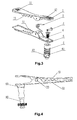
Fig.1 is the whole structure drawing of embodiment 1 of the invention; -
Fig.2 is the assembly diagram of the connection assembly and the clamp ofFig.1 ; -
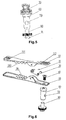
Fig.3 is the exploded view of the embodiment 1; -
Fig.4 is the whole structure drawing ofembodiment 2 of the invention; -
Fig.5 is the assembly diagram of the connection assembly and the clamp ofFig.4 ; -
Fig.6 is the exploded view of theembodiment 2; -
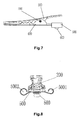
Fig.7 is the whole structure drawing ofembodiment 3 of the invention; -
Fig.8 is the assembly diagram of the connection assembly and the clamp ofFig.7 ; -
Fig.9 is the exploded view of theembodiment 3. - Further explanation to the invention is stated below by three embodiment of implementation combining with the attached figures:
- The multi-function clamp for veterinarians as shown in
Fig.1, Fig.2 andFig.3 is comprised by upper clip 1,lower clip 5,bolt 3,torsional spring 2 and the connection assembly, where, the connection assembly includes a dual-bore copper 6 wherein the dual-bore copper 6 has two mounting holes and one M3*6chamfer head screw 4; when assembling, put thelower clip 5 in a plane surface, install the M3*6chamfer head screw 4 with the dual-bore copper 6 by passing through thelower clip 5, then lock the dual-bore copper 6 in thelower clip 5, at the time thetorsional spring 2 is placed in thelower clip 5, cover the upper clip 1 and put on thebolt 3, then press-riveting the upper clip 1 and thelower clip 5 to form an integral clamp for veterinarian. Thereinto, the tail end of the upper clip 1 haswavy stripes 12, for which the main purpose of the stripes is to prevent the clamp drop from the users; the front end of the upper clip 1 has multiplecircular dots 11, and between the upper clip 1 and thelower clip 5 has a plurality ofsecond teeth 13 and a plurality offirst teeth 51 engaging with thesecond teeth 13 in separately to prevent the clamp loosing from the animal skins. - The embodiment applies to different types of lead wires, the dual-
bore copper 6 has mountingholes 61 with a diameter of 3mm and mounting holes62 with a diameter of 4mm, and at the bottom of the dual-bore copper 6 hassnap plug 63 with a diameter of 4mm; when the user using the electrocardiogram (hereinafter refers as "ECG") cable, if it is a probe-type with a diameter of 3mm, insert the lead wires into themounting holes 61 with a diameter of 3mm for normal usage; if the ECG cable is banana plug type with a diameter of 4mm, insert the lead wires into themounting holes 62 with a diameter of 4mm for normal usage; if the ECG cable is snap-type with a diameter of 4mm, insert the lead wires into thesnap plug 63 with a diameter of 4mm for normal usage. - The multi-function clamp for veterinarians as shown in
Fig.4 ,Fig.5 and Fig.6 is comprised byupper clip 10,lower clip 50,bolt 30,torsional spring 20 and the connection assembly, where, the connection assembly includes a M3*6chamfer head screw 40, single-hole copper 60 andhand screw 80; when assembling, put thelower clip 50 in a plane surface, install the M3*6chamfer head screw 40 with the single-hole copper 60 by passing through thelower clip 50, then lock the single-hole copper 60 in thelower clip 50, at the time thetorsional spring 20 is placed inside thelower clip 50, cover theupper clip 10 and put on thebolt 30, then press-riveting theupper clip 10 and thelower clip 50, at last screw thehand screw 80 into the single-hole copper 60. The single-hole copper 60 of the embodiment has mountingholes 70 with a diameter of 4mm and thehand screw 80 hassnap plug 81 with a diameter of 4mm; when the user using the ECG cable, if it is a probe-type with a diameter of 3mm or banana plug type with a diameter of 4mm, insert the lead wires into themounting holes 70 with a diameter of 4mm and then screw thehand screw 80 tightly to fix the lead wires for normal usage; if the ECG cable is snap-type with a diameter of 4mm, insert the lead wires into thesnap plug 81 with a diameter of 4mm for normal usage. - Thereinto, the tail end of the
upper clip 10 haswavy stripes 102, for which the main purpose of the stripes is to prevent the clamp drop from the users; the front end of theupper clip 10 has multiplecircular dots 101, and between theupper clip 10 and thelower clip 50 has a plurality ofsecond teeth 103 and a plurality offirst teeth 501 engaging with thesecond teeth 103 in separately to prevent the clamp loosing from the animal skins. - The multi-function clamp for veterinarians as shown in
Fig.7, Fig.8 andFig.9 is comprised byupper clip 100,lower clip 400,bolt 300,torsional spring 200 and the connection assembly, where, the connection assembly includes a double-headed electrode socket 500 and rivet 600, wherein the bottom of therivet 600 has a snap plug; when assembling the clamp for veterinarians, lay flat thelower clip 400, using therivet 600 to press-rivet the double-headed electrode socket 500 in thelower clip 400, and put thetorsional spring 200 in thelower clip 400, then cover theupper clip 100, pass through thebolt 300, and then press-rivet theupper clip 100 and thelower clip 400. Thereinto, the tail end of theupper clip 100 haswavy stripes 1002, for which the main purpose of the stripes is to prevent the clamp drop from the users; the front end of theupper clip 100 has multiplecircular dots 1001, and between theupper clip 100 and thelower clip 400 has a plurality ofsecond teeth 1003 and a plurality of first teeth 4001engaging with thesecond teeth 1003 in separately to prevent the clamp loosing from the animal skins. The double-headed electrode socket 500 of the embodiment hasprobe holes 5001 with a diameter of 3mm andprobe holes 5002 with a diameter of 4mm, and at the bottom of the snap-rivet 600 hassnap plug 63 with a diameter of 4mm; when the user using the ECG cable, if it is a probe-type with a diameter of 3mm, insert the lead wires into theprobe holes 5001 for normal usage; if the ECG cable is banana plug type with a diameter of 4mm, insert the lead wires into theprobe holes 5002 with a diameter of 4mm for normal usage; if the ECG cable is snap-type with a diameter of 4mm, insert the lead wires into the snap plug with a diameter of 4mm for normal usage.
Claims (10)
- A multi-function clamp for veterinarians, comprising a clamp body comprising an upper clip (1, 10, 100), a lower clip (5, 50, 400), a bolt (3, 30, 300) and a torsional spring (2, 20, 200); the clamp body being installed with a connection assembly connectable to lead wires, characterized in that the connection assembly comprises several installation sections which can match with different types of lead wire plugs.
- The multi-function clamp for veterinarians according to claim 1, characterized in that the connection assembly comprises a dual-bore copper (6) and a chamfer head screw (4, 40), the chamfer head screw (4, 40) passes through the lower clip (5, 50, 400) to install with the dual-bore copper (6), so as to install the dual-bore copper (6) in the lower clip (5, 50, 400).
- The multi-function clamp for veterinarians according to claim 2, characterized in that the bottom of the dual-bore copper (6) comprises a snap, wherein side of the dual-bore copper (6) defines a pair of mounting holes (61, 62) having a diameter of 3mm and 4mm respectively, while the one of the pair of mounting holes (61, 62) is perpendicular to another one of the pair of mounting holes (61, 62) in the axial direction of the holes.
- The multi-function clamp for veterinarians according to claim 1, characterized in that the connection assembly comprises a chamfer head screw (4, 40), a single-hole copper (60) and a hand screw (80), wherein the chamfer head screw (4, 40) passes through the lower clip (5, 50, 400) to install with the single-hole copper (60), so as to lock the single-hole copper (60) in the lower clip (5, 50, 400).
- The multi-function clamp for veterinarians according to claim 4, characterized in that the side face of the single-hole copper (60) defines a mounting hole (70) having a diameter of 4mm, wherein the mounting hole (70) installs with the lead wire plug and the hand screw (80) is screwed into the single-hole copper (60), while the hand screw (80) tightly fixes the lead wire plug on the single-hole copper (60).
- The multi-function clamp for veterinarians according to claim 4 or claim 5, characterized in that the bottom of the hand screw (80) is a snap.
- The multi-function clamp for veterinarians according to claim 1, characterized in that the connection assembly comprises a double-headed electrode socket (500) and a rivet (600), wherein the rivet (600) matches with the double-headed electrode socket (500), so as to install the double-headed electrode socket (500) in the lower clip (5, 50, 400).
- The multi-function clamp for veterinarians according to claim 7, characterized in that the double-headed electrode socket (500) defines a pair of mounting holes (5001, 5002) having a diameter of 3mm and 4mm respectively, and located at two flanks of the double-headed electrode socket (500) respectively, while the bottom of the rivet (600) is a snap.
- The multi-function clamp for veterinarians according to claim 1, characterized in that the lower clip (5, 50, 400) comprises a plurality of first teeth (51, 501, 4001), and the connection assembly is located at a tail end of the lower clip (5, 50, 400).
- The multi-function clamp for veterinarians according to claim 9, characterized in that a tail end of the upper clip (1, 10, 100) comprises a plurality of wavy stripes (12, 102, 1002), and a front end of the upper clip (1, 10, 100) defines multiple dots (11, 101, 1001), and the upper clip (1, 10, 100) comprises a plurality of second teeth (13, 103, 1003) engaging with the first teeth (51, 501, 1003) on the lower clip (5, 50, 400).
Applications Claiming Priority (2)
| Application Number | Priority Date | Filing Date | Title |
|---|---|---|---|
| CN2010201032280U CN201591552U (en) | 2010-01-22 | 2010-01-22 | A multifunctional veterinary clip |
| PCT/CN2010/070514 WO2011088625A1 (en) | 2010-01-22 | 2010-02-04 | Multifunctional clamp for animal |
Publications (3)
| Publication Number | Publication Date |
|---|---|
| EP2526860A1 EP2526860A1 (en) | 2012-11-28 |
| EP2526860A4 EP2526860A4 (en) | 2013-09-18 |
| EP2526860B1 true EP2526860B1 (en) | 2014-10-15 |
Family
ID=42773614
Family Applications (1)
| Application Number | Title | Priority Date | Filing Date |
|---|---|---|---|
| EP10810730.1A Active EP2526860B1 (en) | 2010-01-22 | 2010-02-04 | Multifunctional clamp for veterinarians |
Country Status (4)
| Country | Link |
|---|---|
| US (1) | US8430681B2 (en) |
| EP (1) | EP2526860B1 (en) |
| CN (1) | CN201591552U (en) |
| WO (1) | WO2011088625A1 (en) |
Families Citing this family (12)
| Publication number | Priority date | Publication date | Assignee | Title |
|---|---|---|---|---|
| CN102133098B (en) * | 2010-01-22 | 2014-06-25 | 深圳市理邦精密仪器股份有限公司 | Multipurpose clamp for animal |
| US20130324827A1 (en) * | 2012-05-31 | 2013-12-05 | Dennis Burkett | Atraumtic Clamp-Type Electrode Contact |
| CN105263565B (en) * | 2013-06-07 | 2018-06-05 | 皇家飞利浦有限公司 | Electrode for medical service and the limbs fixture for ECG device |
| WO2014194511A2 (en) * | 2013-06-07 | 2014-12-11 | Koninklijke Philips N.V. | Medical electrode and limb clamp for an ecg device |
| US9225155B1 (en) * | 2013-09-04 | 2015-12-29 | James B. Rauckman | Safety cover and identifier for electric terminal block |
| US9755331B2 (en) | 2015-01-07 | 2017-09-05 | William Ernest Swan | Electrical wire connector |
| US10117593B2 (en) * | 2016-08-04 | 2018-11-06 | Zentan Technology Co., Ltd. | Physiological signal detection clamp |
| CN208677386U (en) * | 2017-10-25 | 2019-04-02 | 深圳市元和电子材料有限公司 | A kind of multi-functional switching folder |
| CN108310624A (en) * | 2018-04-23 | 2018-07-24 | 江苏中普科技有限公司 | A kind of attachment device of self-locking collet and electrode slice |
| CN109066254B (en) * | 2018-07-16 | 2020-02-04 | 国网山东省电力公司烟台供电公司 | Multifunctional clamp for meter installation and power connection |
| CN111244705B (en) * | 2020-01-07 | 2021-08-06 | 中国科学院大学宁波华美医院 | A test connecting wire for implantation of artificial cardiac pacemaker |
| CN111544242B (en) * | 2020-05-14 | 2022-03-11 | 中国人民解放军陆军军医大学第一附属医院 | An anatomical table for an animal model |
Family Cites Families (12)
| Publication number | Priority date | Publication date | Assignee | Title |
|---|---|---|---|---|
| US2491552A (en) * | 1946-07-26 | 1949-12-20 | Grace Carl Tom De | Electric trouble light |
| US3506944A (en) * | 1968-04-16 | 1970-04-14 | Lumidor Products Corp | Clip-type wire connector |
| US3641473A (en) * | 1970-05-28 | 1972-02-08 | Thomas J Attaway | Vehicle-grounding clamp |
| US4057313A (en) * | 1976-07-19 | 1977-11-08 | Ida Polizzano | Test clip |
| US4640563A (en) * | 1985-06-10 | 1987-02-03 | The Leblanc Corporation | Universal clasp structure for external electrode probes |
| CN85202339U (en) | 1985-06-19 | 1986-04-02 | 福田电子株式会社 | Clip-on Electrodes for ECG Machines |
| CN85202644U (en) * | 1985-07-02 | 1987-07-01 | 福田电机株式会社 | Clip-type electrode for electrocardiogram machine |
| DE19643988C1 (en) * | 1996-10-31 | 1998-04-16 | Nicolay Verwaltungs Gmbh | Contact clamp for skin electrodes made in largely x=ray transparent materials |
| CN2845719Y (en) * | 2005-12-06 | 2006-12-13 | 栾桂芹 | Anti-interference electrocardiogram conductor |
| DE102007059096B4 (en) * | 2007-12-07 | 2014-05-15 | Nicolay Verwaltungs-Gmbh | Electrode terminal for electrically contacting a film electrode and a push button electrode |
| CN201167950Y (en) * | 2008-03-06 | 2008-12-24 | 郑霞 | Online electrode of electrocardiograph |
| CN201312804Y (en) | 2008-12-18 | 2009-09-23 | 深圳市理邦精密仪器有限公司 | Novel limb electrode |
-
2010
- 2010-01-22 CN CN2010201032280U patent/CN201591552U/en not_active Expired - Lifetime
- 2010-02-04 EP EP10810730.1A patent/EP2526860B1/en active Active
- 2010-02-04 US US13/057,139 patent/US8430681B2/en active Active
- 2010-02-04 WO PCT/CN2010/070514 patent/WO2011088625A1/en not_active Ceased
Also Published As
| Publication number | Publication date |
|---|---|
| WO2011088625A1 (en) | 2011-07-28 |
| EP2526860A1 (en) | 2012-11-28 |
| CN201591552U (en) | 2010-09-29 |
| US20120272489A1 (en) | 2012-11-01 |
| EP2526860A4 (en) | 2013-09-18 |
| US8430681B2 (en) | 2013-04-30 |
Similar Documents
| Publication | Publication Date | Title |
|---|---|---|
| US8430681B2 (en) | Multi-function clip to engage different types of electrical leads | |
| EP1947743A3 (en) | Electrical Connector Body having a transverse hold-down Beam for a shroud-integrated Lock Arm | |
| US20160111799A1 (en) | Battery Terminal | |
| CN108501837B (en) | Automobile plug-in for fixing wire | |
| DE102006049192A1 (en) | Shielded plug on the cable side | |
| US20170094809A1 (en) | Apparatus for Assembling Light-Emitting Diode Lighting Fixtures | |
| CN113964719A (en) | Installation bird repellent device | |
| CN211844114U (en) | Cable chuck and fill electric pile | |
| US7770249B2 (en) | Wiring harness tooling device | |
| CN210027298U (en) | Wire protection structure for automobile wire harness | |
| CN203553373U (en) | Grounding clamp of cable connector for clamping ground wire | |
| CN102133098B (en) | Multipurpose clamp for animal | |
| CN110137710B (en) | Equipment wire clamp | |
| CN102651507A (en) | Wire connector | |
| CN111119843B (en) | Control nipple | |
| CN105090614A (en) | Wire harness fixing clamp and electric appliance | |
| CN216903551U (en) | Handheld device cable fixing assembly | |
| CN211299923U (en) | Fixation clamp and sleep monitor | |
| CN101562319A (en) | Fastening device for detachable holding of an electrical distributor by latching | |
| KR200454624Y1 (en) | connector | |
| CN201167950Y (en) | Online electrode of electrocardiograph | |
| CN210603354U (en) | Anti-broken wire sensor | |
| CN221177139U (en) | Wiring harness fixture | |
| CN223369351U (en) | An extended handle | |
| US9060422B2 (en) | Electric wiring seat and assembly thereof |
Legal Events
| Date | Code | Title | Description |
|---|---|---|---|
| PUAI | Public reference made under article 153(3) epc to a published international application that has entered the european phase |
Free format text: ORIGINAL CODE: 0009012 |
|
| 17P | Request for examination filed |
Effective date: 20110225 |
|
| AK | Designated contracting states |
Kind code of ref document: A1 Designated state(s): AT BE BG CH CY CZ DE DK EE ES FI FR GB GR HR HU IE IS IT LI LT LU LV MC MK MT NL NO PL PT RO SE SI SK SM TR |
|
| DAX | Request for extension of the european patent (deleted) | ||
| A4 | Supplementary search report drawn up and despatched |
Effective date: 20130820 |
|
| RIC1 | Information provided on ipc code assigned before grant |
Ipc: A61D 1/00 20060101ALI20130813BHEP Ipc: A61B 5/0408 20060101AFI20130813BHEP |
|
| GRAP | Despatch of communication of intention to grant a patent |
Free format text: ORIGINAL CODE: EPIDOSNIGR1 |
|
| RAP1 | Party data changed (applicant data changed or rights of an application transferred) |
Owner name: EDAN INSTRUMENTS, INC. |
|
| INTG | Intention to grant announced |
Effective date: 20140512 |
|
| GRAS | Grant fee paid |
Free format text: ORIGINAL CODE: EPIDOSNIGR3 |
|
| GRAA | (expected) grant |
Free format text: ORIGINAL CODE: 0009210 |
|
| AK | Designated contracting states |
Kind code of ref document: B1 Designated state(s): AT BE BG CH CY CZ DE DK EE ES FI FR GB GR HR HU IE IS IT LI LT LU LV MC MK MT NL NO PL PT RO SE SI SK SM TR |
|
| REG | Reference to a national code |
Ref country code: GB Ref legal event code: FG4D Ref country code: CH Ref legal event code: EP |
|
| REG | Reference to a national code |
Ref country code: IE Ref legal event code: FG4D |
|
| REG | Reference to a national code |
Ref country code: AT Ref legal event code: REF Ref document number: 691254 Country of ref document: AT Kind code of ref document: T Effective date: 20141115 |
|
| REG | Reference to a national code |
Ref country code: DE Ref legal event code: R096 Ref document number: 602010019609 Country of ref document: DE Effective date: 20141127 |
|
| REG | Reference to a national code |
Ref country code: NL Ref legal event code: VDEP Effective date: 20141015 |
|
| REG | Reference to a national code |
Ref country code: AT Ref legal event code: MK05 Ref document number: 691254 Country of ref document: AT Kind code of ref document: T Effective date: 20141015 |
|
| REG | Reference to a national code |
Ref country code: LT Ref legal event code: MG4D |
|
| PG25 | Lapsed in a contracting state [announced via postgrant information from national office to epo] |
Ref country code: NL Free format text: LAPSE BECAUSE OF FAILURE TO SUBMIT A TRANSLATION OF THE DESCRIPTION OR TO PAY THE FEE WITHIN THE PRESCRIBED TIME-LIMIT Effective date: 20141015 |
|
| PG25 | Lapsed in a contracting state [announced via postgrant information from national office to epo] |
Ref country code: NO Free format text: LAPSE BECAUSE OF FAILURE TO SUBMIT A TRANSLATION OF THE DESCRIPTION OR TO PAY THE FEE WITHIN THE PRESCRIBED TIME-LIMIT Effective date: 20150115 Ref country code: PT Free format text: LAPSE BECAUSE OF FAILURE TO SUBMIT A TRANSLATION OF THE DESCRIPTION OR TO PAY THE FEE WITHIN THE PRESCRIBED TIME-LIMIT Effective date: 20150216 Ref country code: LT Free format text: LAPSE BECAUSE OF FAILURE TO SUBMIT A TRANSLATION OF THE DESCRIPTION OR TO PAY THE FEE WITHIN THE PRESCRIBED TIME-LIMIT Effective date: 20141015 Ref country code: IS Free format text: LAPSE BECAUSE OF FAILURE TO SUBMIT A TRANSLATION OF THE DESCRIPTION OR TO PAY THE FEE WITHIN THE PRESCRIBED TIME-LIMIT Effective date: 20150215 Ref country code: ES Free format text: LAPSE BECAUSE OF FAILURE TO SUBMIT A TRANSLATION OF THE DESCRIPTION OR TO PAY THE FEE WITHIN THE PRESCRIBED TIME-LIMIT Effective date: 20141015 Ref country code: FI Free format text: LAPSE BECAUSE OF FAILURE TO SUBMIT A TRANSLATION OF THE DESCRIPTION OR TO PAY THE FEE WITHIN THE PRESCRIBED TIME-LIMIT Effective date: 20141015 |
|
| PG25 | Lapsed in a contracting state [announced via postgrant information from national office to epo] |
Ref country code: LV Free format text: LAPSE BECAUSE OF FAILURE TO SUBMIT A TRANSLATION OF THE DESCRIPTION OR TO PAY THE FEE WITHIN THE PRESCRIBED TIME-LIMIT Effective date: 20141015 Ref country code: HR Free format text: LAPSE BECAUSE OF FAILURE TO SUBMIT A TRANSLATION OF THE DESCRIPTION OR TO PAY THE FEE WITHIN THE PRESCRIBED TIME-LIMIT Effective date: 20141015 Ref country code: SE Free format text: LAPSE BECAUSE OF FAILURE TO SUBMIT A TRANSLATION OF THE DESCRIPTION OR TO PAY THE FEE WITHIN THE PRESCRIBED TIME-LIMIT Effective date: 20141015 Ref country code: CY Free format text: LAPSE BECAUSE OF FAILURE TO SUBMIT A TRANSLATION OF THE DESCRIPTION OR TO PAY THE FEE WITHIN THE PRESCRIBED TIME-LIMIT Effective date: 20141015 Ref country code: PL Free format text: LAPSE BECAUSE OF FAILURE TO SUBMIT A TRANSLATION OF THE DESCRIPTION OR TO PAY THE FEE WITHIN THE PRESCRIBED TIME-LIMIT Effective date: 20141015 Ref country code: GR Free format text: LAPSE BECAUSE OF FAILURE TO SUBMIT A TRANSLATION OF THE DESCRIPTION OR TO PAY THE FEE WITHIN THE PRESCRIBED TIME-LIMIT Effective date: 20150116 Ref country code: AT Free format text: LAPSE BECAUSE OF FAILURE TO SUBMIT A TRANSLATION OF THE DESCRIPTION OR TO PAY THE FEE WITHIN THE PRESCRIBED TIME-LIMIT Effective date: 20141015 |
|
| REG | Reference to a national code |
Ref country code: DE Ref legal event code: R097 Ref document number: 602010019609 Country of ref document: DE |
|
| PG25 | Lapsed in a contracting state [announced via postgrant information from national office to epo] |
Ref country code: DK Free format text: LAPSE BECAUSE OF FAILURE TO SUBMIT A TRANSLATION OF THE DESCRIPTION OR TO PAY THE FEE WITHIN THE PRESCRIBED TIME-LIMIT Effective date: 20141015 Ref country code: EE Free format text: LAPSE BECAUSE OF FAILURE TO SUBMIT A TRANSLATION OF THE DESCRIPTION OR TO PAY THE FEE WITHIN THE PRESCRIBED TIME-LIMIT Effective date: 20141015 Ref country code: CZ Free format text: LAPSE BECAUSE OF FAILURE TO SUBMIT A TRANSLATION OF THE DESCRIPTION OR TO PAY THE FEE WITHIN THE PRESCRIBED TIME-LIMIT Effective date: 20141015 Ref country code: RO Free format text: LAPSE BECAUSE OF FAILURE TO SUBMIT A TRANSLATION OF THE DESCRIPTION OR TO PAY THE FEE WITHIN THE PRESCRIBED TIME-LIMIT Effective date: 20141015 Ref country code: SK Free format text: LAPSE BECAUSE OF FAILURE TO SUBMIT A TRANSLATION OF THE DESCRIPTION OR TO PAY THE FEE WITHIN THE PRESCRIBED TIME-LIMIT Effective date: 20141015 |
|
| PLBE | No opposition filed within time limit |
Free format text: ORIGINAL CODE: 0009261 |
|
| STAA | Information on the status of an ep patent application or granted ep patent |
Free format text: STATUS: NO OPPOSITION FILED WITHIN TIME LIMIT |
|
| PG25 | Lapsed in a contracting state [announced via postgrant information from national office to epo] |
Ref country code: IT Free format text: LAPSE BECAUSE OF FAILURE TO SUBMIT A TRANSLATION OF THE DESCRIPTION OR TO PAY THE FEE WITHIN THE PRESCRIBED TIME-LIMIT Effective date: 20141015 |
|
| 26N | No opposition filed |
Effective date: 20150716 |
|
| PG25 | Lapsed in a contracting state [announced via postgrant information from national office to epo] |
Ref country code: LU Free format text: LAPSE BECAUSE OF FAILURE TO SUBMIT A TRANSLATION OF THE DESCRIPTION OR TO PAY THE FEE WITHIN THE PRESCRIBED TIME-LIMIT Effective date: 20150204 |
|
| REG | Reference to a national code |
Ref country code: CH Ref legal event code: PL |
|
| GBPC | Gb: european patent ceased through non-payment of renewal fee |
Effective date: 20150204 |
|
| PG25 | Lapsed in a contracting state [announced via postgrant information from national office to epo] |
Ref country code: LI Free format text: LAPSE BECAUSE OF NON-PAYMENT OF DUE FEES Effective date: 20150228 Ref country code: CH Free format text: LAPSE BECAUSE OF NON-PAYMENT OF DUE FEES Effective date: 20150228 Ref country code: MC Free format text: LAPSE BECAUSE OF FAILURE TO SUBMIT A TRANSLATION OF THE DESCRIPTION OR TO PAY THE FEE WITHIN THE PRESCRIBED TIME-LIMIT Effective date: 20141015 |
|
| REG | Reference to a national code |
Ref country code: IE Ref legal event code: MM4A |
|
| REG | Reference to a national code |
Ref country code: FR Ref legal event code: ST Effective date: 20151030 |
|
| PG25 | Lapsed in a contracting state [announced via postgrant information from national office to epo] |
Ref country code: GB Free format text: LAPSE BECAUSE OF NON-PAYMENT OF DUE FEES Effective date: 20150204 Ref country code: IE Free format text: LAPSE BECAUSE OF NON-PAYMENT OF DUE FEES Effective date: 20150204 |
|
| PG25 | Lapsed in a contracting state [announced via postgrant information from national office to epo] |
Ref country code: SI Free format text: LAPSE BECAUSE OF FAILURE TO SUBMIT A TRANSLATION OF THE DESCRIPTION OR TO PAY THE FEE WITHIN THE PRESCRIBED TIME-LIMIT Effective date: 20141015 Ref country code: FR Free format text: LAPSE BECAUSE OF NON-PAYMENT OF DUE FEES Effective date: 20150302 |
|
| PG25 | Lapsed in a contracting state [announced via postgrant information from national office to epo] |
Ref country code: MT Free format text: LAPSE BECAUSE OF FAILURE TO SUBMIT A TRANSLATION OF THE DESCRIPTION OR TO PAY THE FEE WITHIN THE PRESCRIBED TIME-LIMIT Effective date: 20141015 |
|
| PG25 | Lapsed in a contracting state [announced via postgrant information from national office to epo] |
Ref country code: SM Free format text: LAPSE BECAUSE OF FAILURE TO SUBMIT A TRANSLATION OF THE DESCRIPTION OR TO PAY THE FEE WITHIN THE PRESCRIBED TIME-LIMIT Effective date: 20141015 Ref country code: HU Free format text: LAPSE BECAUSE OF FAILURE TO SUBMIT A TRANSLATION OF THE DESCRIPTION OR TO PAY THE FEE WITHIN THE PRESCRIBED TIME-LIMIT; INVALID AB INITIO Effective date: 20100204 Ref country code: BG Free format text: LAPSE BECAUSE OF FAILURE TO SUBMIT A TRANSLATION OF THE DESCRIPTION OR TO PAY THE FEE WITHIN THE PRESCRIBED TIME-LIMIT Effective date: 20141015 |
|
| PG25 | Lapsed in a contracting state [announced via postgrant information from national office to epo] |
Ref country code: TR Free format text: LAPSE BECAUSE OF FAILURE TO SUBMIT A TRANSLATION OF THE DESCRIPTION OR TO PAY THE FEE WITHIN THE PRESCRIBED TIME-LIMIT Effective date: 20141015 |
|
| PG25 | Lapsed in a contracting state [announced via postgrant information from national office to epo] |
Ref country code: BE Free format text: LAPSE BECAUSE OF FAILURE TO SUBMIT A TRANSLATION OF THE DESCRIPTION OR TO PAY THE FEE WITHIN THE PRESCRIBED TIME-LIMIT Effective date: 20141015 |
|
| PG25 | Lapsed in a contracting state [announced via postgrant information from national office to epo] |
Ref country code: MK Free format text: LAPSE BECAUSE OF FAILURE TO SUBMIT A TRANSLATION OF THE DESCRIPTION OR TO PAY THE FEE WITHIN THE PRESCRIBED TIME-LIMIT Effective date: 20141015 |
|
| REG | Reference to a national code |
Ref country code: DE Ref legal event code: R079 Ref document number: 602010019609 Country of ref document: DE Free format text: PREVIOUS MAIN CLASS: A61B0005040800 Ipc: A61B0005280000 |
|
| PGFP | Annual fee paid to national office [announced via postgrant information from national office to epo] |
Ref country code: DE Payment date: 20260206 Year of fee payment: 17 |