EP2526655B1 - Steuergerät und anordnungen mit einem steuergerät - Google Patents
Steuergerät und anordnungen mit einem steuergerät Download PDFInfo
- Publication number
- EP2526655B1 EP2526655B1 EP12702969.2A EP12702969A EP2526655B1 EP 2526655 B1 EP2526655 B1 EP 2526655B1 EP 12702969 A EP12702969 A EP 12702969A EP 2526655 B1 EP2526655 B1 EP 2526655B1
- Authority
- EP
- European Patent Office
- Prior art keywords
- layer
- control device
- electronic device
- interface
- hardware
- Prior art date
- Legal status (The legal status is an assumption and is not a legal conclusion. Google has not performed a legal analysis and makes no representation as to the accuracy of the status listed.)
- Active
Links
Images

Classifications
-
- H—ELECTRICITY
- H04—ELECTRIC COMMUNICATION TECHNIQUE
- H04L—TRANSMISSION OF DIGITAL INFORMATION, e.g. TELEGRAPHIC COMMUNICATION
- H04L12/00—Data switching networks
- H04L12/28—Data switching networks characterised by path configuration, e.g. LAN [Local Area Networks] or WAN [Wide Area Networks]
- H04L12/40—Bus networks
- H04L12/40006—Architecture of a communication node
-
- H—ELECTRICITY
- H04—ELECTRIC COMMUNICATION TECHNIQUE
- H04L—TRANSMISSION OF DIGITAL INFORMATION, e.g. TELEGRAPHIC COMMUNICATION
- H04L12/00—Data switching networks
- H04L12/28—Data switching networks characterised by path configuration, e.g. LAN [Local Area Networks] or WAN [Wide Area Networks]
- H04L12/40—Bus networks
- H04L2012/40208—Bus networks characterized by the use of a particular bus standard
- H04L2012/40215—Controller Area Network CAN
Definitions
- the invention relates to a hybrid device according to the preamble of claim 1.
- An arrangement for remote control of a mobile radiotelephone in a motor vehicle comprises an independent interface module, which also produces a standardized interface to a CAN bus as an output unit, wherein the interface module also comprises a communication management unit, in which a conversion of the data formats takes place between the radiotelephone and the output unit.
- the communication management unit must have the device-specific instruction sets for data transmission, so that they can make the conversion of the data formats between the radio telephone and the input and output unit.
- an arrangement according to the prior art is translated by means of the interface module with the use of computing power between the language of the vehicle bus and the language of the mobile radiotelephone.
- a communication module that includes a housing, a modular plug for insertion into a diagnostic interface of the vehicle diagnostic system, and a transceiver configured to communicate with a mobile telephone having wireless access to a data network.
- a system for analyzing data of a vehicle on-board computer comprising an adapter, a communication means and a server system for the Internet.
- Publication XP 26649767 A describes the requirements and benefits of open communication and defines the basic requirements for interconnecting distributed computing systems.
- the US 2009/0125178 A1 refers to the use of a mobile phone to extract vehicle-related data from a control unit of a vehicle engine and to translate that data into a human-readable form on the display of the mobile phone, simultaneously transmitting the data via an Internet-based system for immediate repair and breakdown assistance become.
- a permanently installed in a vehicle control unit which is designed as a gateway unit or interface unit, supported over the lifetime of the vehicle vehicle-related applications on an electronic device, in particular a mobile phone, which must be calculated that new and more complex applications may well overwhelm the computing power and hardware characteristics of the in-vehicle controller.
- the object of the invention is to propose a hybrid device, which simplifies integration and connection of the electronic device in or on a vehicle bus and increases their performance.
- the core of the invention is a shift of part of the functionality of a control device into another, electronic device that carries the application.
- the core of the invention is thus a shift of a part of the functions or layers of the control device in the electronic device, which is designed in particular as a mobile phone, the realization of a part of the original control device functions software technology in an installable on a hardware of the electronic device application he follows.
- the control unit is relieved as an interface between an application on the electronic device and the vehicle bus by reducing the tasks of the interface to a pure switching and transport function.
- a bus implementation for example, a CAN bus implementation
- essential functional components or the application-related layers of a bus implementation are not executed in the control unit, but are relocated to the application, which is supported by the electronic device.
- a part of the computing power, which is provided in the control unit relocated to the electronic device.
- the data link layer is split between the controller and the electronic device and forms the basis of the connection between the two implementations.
- a control unit means a gateway unit or interface unit, wherein a gateway unit in the context of the invention is an electronic device which enables the connection of an electronic device to a vehicle bus and wherein an interface unit in According to the invention is an electronic device that allows communication as an interface between the vehicle and the electronic device, the electronic device is designed in particular as a mobile electronic device and in particular as a mobile phone.
- FIG. 1 an arrangement A arranged in a vehicle 100 is shown, which comprises a control unit 1, an electronic device 16, a vehicle bus 4 and further bus subscribers 33 and 34.
- a hybrid device 17 is shown, which comprises the connected to the vehicle bus 4 control unit 1 and the electronic device 16, wherein the electronic device 16 is designed as a mobile electronic device 31 and in particular as a mobile electronic communication device 32 such as mobile phone. If the two devices 1 and 16 are connected via a bidirectional communication link 22, these form a physically consisting of two devices two-part control unit 30, which is also referred to as a two-part adhoc control unit, since here two terminals work together wirelessly if necessary.
- an application 24 is installed on each of the electronic devices suitable for cooperation, by means of which the upper layers 25, 26, 27, 28 of a layer model 6 used to complete the physical control device 1 are implemented.
- the upper layers 24-28 are the application layer 25a, the presentation layer 26a, the session layer 27a, and the transport layer 28a.
- the application 24 is adapted in each case in particular to the vehicle 100 and / or in particular to the control device 1 and / or in particular to the electronic device 16.
- the application 24 is as a software program or so-called app for at least one certain arrangement of a particular electronic device, a specific controller and a specific vehicle provided.
- the arrangement according to the invention by the choice of the appropriate application to use the vehicle bus for bidirectional communication with other bus users with each application-capable electronic device via the control unit arranged in the vehicle, without any changes in the vehicle or on the control unit 1 Updates must be made.
- the application 24 By installing the application 24 on a freely programmable hardware 21 of the electronic device 16, the upper layers 25-28 of the layer model 6 used are implemented there.
- the data packets 35 generated in the electronic device 16 are transferred out of the application 24 and, in particular, out of the transport layer 28a the bidirectional communication link 22 is transmitted to the control unit 1.
- the transmission takes place wirelessly via an interface 20 of the electronic device 16 to an interface 15 of the control device 1.
- the interfaces 20 and 15 are each formed as a Bluetooth transceiver and have as layers 29 and 23 each have a data link layer 29 a or 23a on. According to an embodiment variant, not shown, it is also provided to transmit the data packets 35 without the use of a special Bluetooth protocol.
- the control unit 1 comprises a hardware 5, on which three layers 11, 12 and 13 of the layer model 13 used are implemented.
- the layers 11-13 are a network layer 11a, a data link layer 12a and a physical layer 13a.
- the interface 15, from which the data packets 35 emitted by the electronic device 16 are received, is connected to the data link layer 12a of the control device 1.
- the incoming data packets 35 are using the network layer 11a addressed to bus subscribers 33, 34 and from the physical layer 13a to the vehicle bus 4, which is designed as CAN-BUS 19, set.
- the vehicle bus 4 or the CAN-BUS 19 forms a network N, via which the bus subscribers 33, 34 and the control unit 1, which is also to be understood as a bus subscriber, are connected.
- the physical layer 13a is connected to a further interface 14 via which the control unit 1 is connected to the vehicle bus 4.
- data packets 36 which are addressed by one of the bus subscribers 33, 34 to the control unit 1, passed through the interface 14 of the controller 1 in the physical layer 13a and then from the control unit 1, without that in the control unit 1 all layers of the layer model used 6 are passed through the data link layer 12a to the interface 15 of the control unit 1. From this Bluetooth interface 15 then a wireless transmission of the data packets 36 to the Bluetooth interface 20 of the electronic device 16.
- the data packets 36 are then unpacked and output eg visually and / or acoustically to a display D and / or a loudspeaker S.
- the interface 15 of the control unit 1 and the interface 20 of the electronic device 20 are not designed as a Bluetooth transceiver, but each realized by a mechanical connector 37 and 38, respectively.
- it is provided to connect the two devices 1, 16 to a data cable 39 and thus to establish bidirectional communication between the two devices.
- the invention in particular, the plug 37, 38 form as a USB plug and the data cable 39 as a USB data cable.
- it is also provided to connect the two devices while avoiding the use of a data cable via the two plugs directly to each other.
Landscapes
- Engineering & Computer Science (AREA)
- Computer Networks & Wireless Communication (AREA)
- Signal Processing (AREA)
- Small-Scale Networks (AREA)
- Mobile Radio Communication Systems (AREA)
Description
- Die Erfindung betrifft ein Hybridgerät gemäß dem Oberbegriff des Anspruchs 1.
- Aus der
DE 103 10 115 A1 ist eine Anordnung zur Fernbedienung eines mobilen Funktelefons in einem Kraftfahrzeug bekannt. Diese Anordnung umfasst ein eigenständiges Schnittstellenmodul, welches als Ausgabeeinheit auch eine standardisierte Schnittstelle zu einem CAN-Bus herstellt, wobei das Schnittstellenmodul auch eine Kommunikationsmanagementeinheit umfasst, in welcher eine Konvertierung der Datenformate zwischen dem Funktelefon und der Ausgabeeinheit erfolgt. Nachteilig an dieser Anordnung ist, dass die Kommunikationsmanagementeinheit über die gerätespezifischen Befehlssätze zur Datenübertragung verfügen muss, damit diese die Umwandlung der Datenformate zwischen dem Funktelefon und der Ein- und Ausgabeeinheit vornehmen kann. Bei einer Anordnung entsprechend dem Stand der Technik wird mittels des Schnittstellenmoduls unter Aufwendung von Rechenleistung zwischen der Sprache des Fahrzeugsbusses und der Sprache des mobilen Funktelefons übersetzt. - Aus der
US 2007/0156311 A1 ist ein Kommunikationsmodul bekannt, welches ein Gehäuse, einen Modulstecker zum Einstecken in eine Diagnoseschnittstelle des Fahrzeug-Diagnosesystems und einen Sende-Empfänger umfasst, welcher dazu ausgelegt ist, mit einem Mobiltelefon zu kommunizieren, welches drahtlosen Zugang zu einem Datennetzwerk aufweist. - Aus der
WO 2010/000262 A1 ist ein System zur Analyse von Daten eines Fahrzeugbordcomputers bekannt, wobei das System einen Adapter, ein Kommunikationsmittel und ein Serversystem für das Internet umfasst. - Die Publikation XP 26649767 A beschreibt die Anforderungen und die Vorzüge einer offenen Kommunikation und definiert die grundlegenden Anforderungen für die Verbindung von verteilten Computersystemen.
- Die
US 2009/0125178 A1 bezieht sich auf die Verwendung eines Mobiltelefons zur Extraktion von fahrzeugbezogenen Daten aus einer Kontrolleinheit eines Fahrzeugmotors und auf die Übersetzung dieser Daten in eine vom Menschen lesbare Form auf dem Display des Mobiltelefons, wobei die Daten gleichzeitig über ein internetbasiertes System zur sofortigen Reparatur und zur Pannenhilfe übermittelt werden. - Aus heutiger Sicht muss ein fest in ein Fahrzeug installiertes Steuergerät, das als Gateway-Einheit bzw. Interface-Einheit ausgebildet ist, über die gesamte Lebensdauer des Fahrzeugs fahrzeugbezogene Applikationen auf einem elektronischen Gerät, insbesondere einem Mobiltelefon, unterstützten, wobei einkalkuliert werden muss, dass neue und komplexere Applikationen durchaus die Rechenleistung und Hardware-Ausprägung des im Fahrzeug fest verbauten Steuergeräts überfordern können.
- Aufgabe der Erfindung ist es, ein Hybridgerät vorzuschlagen, welches eine Einbindung bzw. Anbindung des elektronischen Geräts in bzw. an einen Fahrzeugbus vereinfacht und in ihrer Leistungsfähigkeit steigert.
- Weiterhin ist es insbesondere Aufgabe der Erfindung, ein Hybridgerät, welches aufwärtskompatibel ist, ohne dass bei einem Wechsel des elektronischen Geräts an einem im Fahrzeug verbauten Steuergerät eine Aktualisierung erforderlich ist. Weiterhin ist es Aufgabe der Erfindung den Rechenaufwand in einem Steuergerät zu minimieren, welcher beim Betrieb eines elektronischen Geräts an einem Fahrzeugbus erforderlich ist.
- Diese Aufgabe wird ausgehend von den Merkmalen des Oberbegriffs des Anspruchs 1 durch die kennzeichnenden Merkmale des Anspruchs 1. In den Unteransprüchen sind vorteilhafte und zweckmäßige Weiterbildungen angegeben.
- Kern der Erfindung ist eine Verlagerung eines Teils der Funktionalität eines Steuergeräts in ein weiteres, elektronisches Gerät, welches die Applikation trägt. Kern der Erfindung ist somit eine Verlagerung eines Teils der Funktionen bzw. Layer des Steuergeräts in das elektronische Gerät, welches insbesondere als Mobiltelefon ausgebildet ist, wobei die Realisierung eines Teils der originären Steuergerät-Funktionen softwaretechnisch im Rahmen einer auf einer Hardware des elektronischen Geräts installierbaren Applikation erfolgt. Mit anderen Worten wird das Steuergerät als Schnittstelle zwischen einer Applikation auf dem elektronischen Gerät und dem Fahrzeugbus durch eine Reduzierung der Aufgaben der Schnittstelle auf eine reine Vermittlungs- und Transportfunktion entlastet. Hierzu sind wesentliche Funktionsbestandteile bzw. die Applikationsbezogenen Schichten einer Bus-Implementierung z.B. einer CAN-Bus-Implementierung nicht im Steuergerät ausgeführt, sondern sind in die Applikation verlagert, welche von dem elektronischen Gerät getragen wird. Hierdurch wird ein Teil der Rechenleistung, welche an sich im Steuergerät erbracht wird, in das elektronische Gerät verlagert. Dies ist insbesondere deshalb vorteilhaft, weil ein moderneres elektronisches Gerät, welches gegen ein älteres elektronisches Gerät ausgetauscht wird, in der Regel leistungsfähiger ist, und damit die ggf. höheren Anforderungen an die Rechenleistung kompensieren kann und so das Steuergerät trotz höherer Anforderung ohne Nachteile weiter verwendet werden kann. Der Data-Link-Layer ist auf das Steuergerät und das elektronische Gerät aufgeteilt und bildet die Basis der Verbindung zwischen beiden Implementierungen. Hierbei ist es insbesondere vorteilhaft, dass bei der Verwendung unterschiedlicher, eventuell modernisierter elektronischer Geräte kein hardwareseitiges Update eines in dem Fahrzeug verbauten Steuergeräts erfolgen muss. Vielmehr ist die Installation einer geeigneten Applikation auf der Hardware des elektronischen Geräts ausreichend. Damit ist eine volle Aufwärtskompatibilität im Hinblick auf das verwendete elektronische Gerät gewährleistet.
- Weiterhin ist es Kern der Erfindung, eine direkte Kommunikation zwischen dem elektronischen Gerät und dem Steuergerät herzustellen, welche in einer Sprache des angeschlossenen Fahrzeugbusses bzw. in einem für den Data-Link-Layer festgelegten Protokoll erfolgt, so dass in den beteiligten Geräten keine oder nur eine geringfügige Übersetzung der empfangenen bzw. gesendeten Datenpakete erforderlich ist. Somit werden die Datenpakete zwischen den beiden Geräten ohne eine aufwendige Protokollumsetzung ausgetauscht. Hierdurch wird Rechenleistung eingespart, die ansonsten von dem Steuergerät erbracht werden müsste.
- Im Sinne der Erfindung wird unter einem Steuergerät eine Gateway-Einheit bzw. Interface-Einheit verstanden, wobei eine Gateway-Einheit im Sinne der Erfindung ein elektronisches Gerät ist, das die Anbindung eines elektronischen Geräts an einen Fahrzeugbus ermöglicht und wobei eine Interface-Einheit im Sinne der Erfindung ein elektronisches Gerät ist, das als Schnittstelle eine Kommunikation zwischen dem Fahrzeugbus und dem elektronischen Gerät ermöglich, wobei das elektronische Gerät insbesondere als mobiles elektronisches Gerät und insbesondere als Mobiltelefon ausgebildet ist.
- Im Sinne der Erfindung werden die Schichten eines Schichtenmodells, welches beispielsweise sieben als Layer bezeichnete Schichten aufweist, mit den unten genannten Fachbegriffen bezeichnet.
- Die 7. Schicht wird als Application-Layer oder Anwendungsschicht bezeichnet. Die 7. bzw. oberste Schicht ist durch die Anwendung selbst definiert und beinhaltet die eigentliche Applikationssoftware.
- Die 6. Schicht wird als Presentation-Layer oder Darstellungsschicht bezeichnet. Die Darstellungsschicht ist für die Datenkonvertierung und für die Verschlüsselung der Daten verantwortlich.
- Die 5. Schicht wird als Session-Layer oder Sitzungs- bzw. Kommunikationsschicht bezeichnet. Die Steuerungsschicht ist für die Datenflusssteuerung und für die Dialogkontrolle zuständig.
- Die 4. Schicht wird als Transport-Layer oder Transportschicht bezeichnet. Die Transportschicht ist für die Übertragung der Datenpakete zuständig.
- Die 3. Schicht wird als Network-Layer oder Netzwerk- bzw. Vermittlungsschicht bezeichnet. Der Network-Layer bzw. die Vermittlungsschicht ist für den Verbindungsaufbau zuständig. Dazu gehört auch das Routing, die Festlegung des Datenweges.
- Die 2. Schicht wird als Data-Link-Layer oder Sicherungsschicht bezeichnet. Diese Ebene regelt den Zugang zur physikalischen Ebene.
- Die 1. Schicht wird als Physical-Layer oder Bitübertragungsschicht bezeichnet. Die physikalische Ebene beschreibt die physikalische, hardwaretechnische Ebene des Steuergerätes.
- Weitere Einzelheiten der Erfindung werden in der Zeichnung anhand von schematisch dargestellten Ausführungsbeispielen beschrieben.
- Hierbei zeigt:
- Fig. 1
- eine schematische Ansicht einer erfindungsgemäßen Anordnung mit Steuergerät und elektronischem Gerät
und - Fig. 2
- eine Ausführungsvariante zu der in der
Figur 1 gezeigten Anordnung. - In der
Figur 1 ist eine in einem Fahrzeug 100 angeordnete Anordnung A gezeigt, welche ein Steuergerät 1, ein elektronisches Gerät 16, einen Fahrzeugbus 4 und weitere Busteilnehmer 33 und 34 umfasst. In derFigur 1 ist weiterhin ein Hybridgerät 17 gezeigt, welches das an den Fahrzeugbus 4 angeschlossene Steuergerät 1 und das elektronische Gerät 16 umfasst, wobei das elektronische Gerät 16 als mobiles elektronisches Gerät 31 und insbesondere als mobiles elektronische Kommunikationsgerät 32 z.B. Mobiltelefon ausgebildet ist. Wenn die beiden Geräte 1 und 16 über eine bidirektionale Kommunikationsverbindung 22 verbunden sind, bilden diese ein körperlich aus zwei Geräten bestehendes zweiteiliges Steuergerät 30, welches auch als zweiteiliges adhoc-Steuergerät bezeichnet wird, da hier zwei Endgeräte bei Bedarf drahtlos zusammenarbeiten. Hierbei arbeitet dasselbe Steuergerät 1, welches als Fahrzeugsteuergerät 2 und insbesondere als CAN-BUS-Steuergerät 3 ausgebildet ist, mit dem dargestellten elektronischen Gerät 16 oder mit einem anderen, nicht dargestellten elektronischen Gerät zusammen und bildet mit dem jeweiligen elektronischen Gerät jeweils ein Hybrid-Fahrzeugsteuergerät 18, welches als hybrides adhoc-Steuergerät ausgeführt ist. Hierbei ist auf jedem der für die Zusammenarbeit geeigneten elektronischen Geräte eine Applikation 24 installiert, durch welche die zur Komplettierung des körperlich vorhandenen Steuergeräts 1 erforderlichen oberen Layer 25, 26, 27, 28 eines verwendeten Schichtenmodells 6 implementiert sind. Bei den oberen Layern 24 - 28 handelt es sich um den Application-Layer 25a, den Presentation-Layer 26a, den Session-Layer 27a und den Transport-Layer 28a. Die Applikation 24 ist jeweils insbesondere auf das Fahrzeug 100 und/oder insbesondere auf das Steuergerät 1 und/oder insbesondere auf das elektronische Gerät, 16 angepasst. Die Applikation 24 ist als Softwareprogramm bzw. so genanntes App zumindest für eine bestimmte Anordnung aus einem bestimmten elektronischen Gerät, einem bestimmten Steuergerät und einem bestimmten Fahrzeug vorgesehen. Somit ist es mit der erfindungsgemäßen Anordnung durch die Wahl der passenden Applikation möglich, mit jedem applikationsfähigen elektronischen Gerät über das im Fahrzeug angeordnete Steuergerät den Fahrzeugbus zur bidirektionalen Kommunikation mit anderen Busteilnehmern zu nutzen, ohne dass im Fahrzeug bzw. an dem Steuergerät 1 irgendwelche Veränderungen oder Aktualisierungen vorgenommen werden müssen. Durch die Installation der Applikation 24 auf einer frei programmierbaren Hardware 21 des elektronischen Geräts 16 werden dort die oberen Layer 25 - 28 des verwendeten Schichtenmodells 6 implementiert. Hierdurch obliegt der wesentliche Rechenaufwand für das Erstellen von Datenpakten 35, die an den Fahrzeugbus 4 gerichtet sind, dem elektronischen Gerät 16. Die in dem elektronischen Gerät 16 erzeugten Datenpakete 35 werden aus der Applikation 24 heraus und insbesondere aus dem Transport-Layer 28a heraus über die bidirektionale Kommunikationsverbindung 22 an das Steuergerät 1 übermittelt. Die Übermittlung erfolgt drahtlos über eine Schnittstelle 20 des elektronischen Geräts 16 an eine Schnittstelle 15 des Steuergeräts 1. Die Schnittstellen 20 und 15 sind jeweils als Bluetooth-Sende-Empfänger ausgebildet und weisen als Layer 29 bzw. 23 jeweils einen Data-Link-Layer 29a bzw. 23a auf. Gemäß einer nicht dargestellten Ausführungsvariante ist es auch vorgesehen, die Datenpakete 35 ohne Verwendung eines speziellen Bluetooth-Protokolls zu übermitteln. Das Steuergerät 1 umfasst eine Hardware 5, auf welcher drei Layer 11, 12 und 13 des verwendeten Schichtenmodells 13 implementiert sind. Bei den Layern 11 - 13 handelt es sich um einen Network-Layer 11a, einen Data-Link-Layer 12a und einen Physical-Layer 13a. Somit weisen das elektronische Gerät 16 und das Steuergerät 1 zusammen alle sieben Schichten des verwendeten Schichtenmodells 6 auf. Die Schnittstelle 15, von welcher die von dem elektronischen Gerät 16 ausgesendeten Datenpakete 35 empfangen werden, ist an den Data-Link-Layer 12a des Steuergeräts 1 angeschlossen. Die ankommenden Datenpakte 35 werden mit Hilfe des Network-Layers 11a an Busteilnehmer 33, 34 adressiert und vom Physical-Layer 13a auf den Fahrzeugbus 4, welcher als CAN-BUS 19 ausgeführt ist, gesetzt. Der Fahrzeugbus 4 bzw. der CAN-BUS 19 bildet ein Netzwerk N, über welches die Busteilnehmer 33, 34 und das Steuergerät 1, das ebenfalls als Busteilnehmer zu verstehen ist, verbunden sind. Hierzu ist der Physical-Layer 13a mit einer weiteren Schnittstelle 14 verbunden, über welche das Steuergerät 1 an den Fahrzeugbus 4 angeschlossen ist. Umgekehrt werden Datenpakte 36, welche von einem der Busteilnehmer 33, 34 an das Steuergerät 1 adressiert sind, über die Schnittstelle 14 des Steuergeräts 1 in den Physical-Layer 13a geleitet und vom Steuergerät 1 dann, ohne dass im Steuergerät 1 alle Layer des verwendeten Schichtenmodells 6 durchlaufen werden, über den Data-Link-Layer 12a an die Schnittstelle 15 des Steuergeräts 1 geleitet. Von dieser Bluetooth-Schnittstelle 15 erfolgt dann eine drahtlose Übertragung der Datenpakete 36 an die Bluetooth-Schnittstelle 20 des elektronischen Geräts 16. Diese leitet die Datenpakte 36 dann an die in der Hardware 21 des elektronischen Geräts 16 implementierten oberen Layer 25 - 28 des verwendeten Schichtenmodells 6. Hier werden die Datenpakte 36 dann entpackt und z.B. optisch und/oder akustisch an ein Display D und/oder einen Lautsprecher S ausgegeben. Die in dem elektronischen Gerät 16 implementierten Layer 25 - 28 und die in dem rudimentären Steuergerät 1 implementierten Layer 11 - 14 bilden zusammen alle Layer des verwendeten Schichtenmodells 6 und somit den Kern des aus zwei körperlich getrennten bzw. trennbaren und eigenständig funktionierenden Geräten 1, 16 gebildeten Hybrid-Fahrzeugsteuergerät 18. - In der
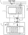
Figur 2 ist die in derFigur 1 gezeigte Anordnung A nochmals dargestellt. Insofern wird auf die Beschreibung zu derFigur 1 verwiesen. Im Unterschied zu derFigur 1 sind die Schnittstelle 15 des Steuergeräts 1 und die Schnittstelle 20 des elektronischen Geräts 20 nicht als Bluetooth-Sende-Empfänger ausgebildet, sondern jeweils durch einen mechanischen Stecker 37 bzw. 38 realisiert. Erfindungsgemäß ist es vorgesehen, die beiden Geräte 1, 16 mit einem Datenkabel 39 zu verbinden und so zwischen den beiden Geräten eine bidirektionale Kommunikation herzustellen. Die Erfindung sieht insbesondere vor, die Stecker 37, 38 als USB-Stecker und das Datenkabel 39 als USB-Datenkabel auszubilden. Gemäß einer nicht dargestellten Ausführungsvariante ist es auch vorgesehen, die beiden Geräte unter Vermeidung der Verwendung eines Datenkabels über die beiden Stecker direkt miteinander zu verbinden. - Die Erfindung ist nicht auf dargestellte oder beschriebene Ausführungsbeispiele beschränkt. Sie umfasst vielmehr Weiterbildungen der Erfindung im Rahmen der Schutzrechtsansprüche.
-
- 1
- Steuergerät
- 2
- Fahrzeugsteuergerät
- 3
- CAN-BUS-Steuergerät
- 4
- Fahrzeugbus
- 5
- Hardware von 1
- 6
- Schichtenmodell
- 7 - 10
- nicht belegt
- 11 - 13
- Layer von 6 in 1
- 11a
- Network-Layer
- 12a
- Data-Link-Layer
- 13
- unterster Layer von 6
- 13a
- Physical-Layer
- 14
- erste Schnittstelle von 1
- 15
- zweite Schnittstelle von 1
- 16
- elektronisches Gerät
- 17
- Hybridgerät
- 18
- Hybrid-Fahrzeugsteuergerät
- 19
- CAN-BUS
- 20
- dritte Schnittstelle von 16
- 21
- frei programmierbare, zweite Hardware von 16
- 22
- bidirektionale Kommunikationsverbindung zwischen 1 und 16
- 23
- Layer von 15 in 16
- 23a
- Data-Link-Layer
- 24
- erste Applikation für 21
- 25 - 28
- obere Layer von 6
- 25a
- Application-Layer
- 26a
- Presentation-Layer
- 27a
- Session-Layer
- 28a
- Transport-Layer
- 29
- Layer von 20
- 29a
- Data-Link-Layer
- 30
- zweiteiliges Steuergerät
- 31
- mobiles elektronisches Gerät
- 32
- mobiles elektronisches Kommunikationsgerät
- 33, 34
- Busteilnehmer
- 35
- Datenpaket von 16 für 4
- 36
- Datenpaket von 33 oder 34 für 1
- 37
- Stecker an 1
- 38
- Stecker an 16
- 39
- Datenkabel
- 100
- Fahrzeug
- A
- Anordnung
- D
- Display von 16
- N
- Netzwerk
- S
- Lautsprecher
Claims (3)
- Hybrid-Fahrzeugsteuergerät (18) zum Anschluss an einen Fahrzeugbus (4), wie zum Beispiel CAN-BUS (19), FlexRay-BUS oder byteflight-BUS, dadurch gekennzeichnet, dass- das Hybridgerät (17) ein Steuergerät (1; 3) und ein elektronisches Gerät (16) umfasst,- wobei das Steuergerät (1) und das elektronische Gerät (16) in einer bidirektionalen Kommunikationsverbindung (22) stehen,- wobei das Steuergerät (1) an den Fahrzeugbus (4) angeschlossen ist,- wobei das Steuergerät (1) ein Gateway für eine auf dem elektronischen Gerät (16) laufende, fahrzeugbezogene Applikation bildet,- dass ein Teil der Funktionalität des Steuergeräts (1; 3) in das weitere, elektronisches Gerät (16), welches eine Applikation trägt, verlagert ist,- wobei das elektronische Gerät (16), als Mobiltelefon ausgebildet ist,- wobei die Realisierung eines Teils der originären Steuergerät-Funktionen softwaretechnisch im Rahmen der auf einer Hardware des elektronischen Geräts (16) als Software installierbaren Applikation erfolgt,- wobei auf einer ersten Hardware (5) des Steuergeräts (1; 3) untere Layer (11 - 13) eines Schichtenmodells (6) implementiert sind,- wobei die Implementierung einen Physical-Layer (13a), einen Data-Link-Layer (12a) und einen Network-Layer (11a) des Schichtenmodells (6) umfasst, wobei der Data-Link-Layer (12a) den Zugang zur physikalischen Ebene regelt und wobei der Network-Layer (11a) für den Verbindungsaufbau zuständig ist,- wobei das elektronische Gerät (16) eine zweite Hardware (21) umfasst,- wobei auf der frei programmierbaren Hardware (21) des elektronischen Geräts (16) die auf das elektronische Gerät (16) und auf das Steuergerät (1; 3) abgestimmte erste Applikation (24) installiert ist, durch welche obere Layer (25 - 28) des Schichtenmodells (6) implementiert sind,- wobei in dem Hybridgerät (17) durch die mit der Kommunikationsverbindung (22) realisierte Verbindung der oberen Layer (25 - 28) des elektronischen Geräts (16) mit den unteren Layern (11 - 13; 11a - 13a) des Steuergeräts (1; 3) ein zweiteiliges Steuergerät (30), insbesondere ein zweiteiliges adhoc-Steuergerät gebildet ist,- wobei das Steuergerät (1; 3) eine erste Schnittstelle (14) und eine zweite Schnittstelle (15) umfasst,- wobei das Steuergerät (1; 3) über die erste Schnittstelle (14) an den Fahrzeugbus (4) angeschlossen ist,- wobei das elektronische Gerät (16) eine dritte Schnittstelle (20) umfasst,- wobei unter Verwendung der zweiten und der dritten Schnittstelle (15, 20) die bidirektionale Kommunikationsverbindung (22) zwischen dem Steuergerät (1; 3) und dem elektronischen Gerät (16) besteht,- wobei die zweite Schnittstelle (15) des Steuergeräts (1; 3) insbesondere mit einem eigenen Layer 23, insbesondere einem Data-Link-Layer (23a) in direkter bidirektionaler Kommunikationsverbindung mit dem auf der ersten Hardware (5) des Steuergeräts (1; 3) implementierten Data-Link-Layer (12a) steht,- wobei auf der Hardware des elektronischen Geräts (16) durch die Applikation (24) insbesondere ein Application-Layer (25a), ein Presentation-Layer (26a), ein Session-Layer (27a) und ein Transport-Layer (28a) implementiert ist und- wobei die dritte Schnittstelle (20) des elektronischen Geräts (16) insbesondere mit einem eigenen Layer (29), insbesondere einem Data-Link-Layer (29a) in direkter bidirektionaler Kommunikationsverbindung mit einem der dem auf der zweiten Hardware (21) des elektronischen Geräts (16) implementierten Layer (25 - 28), insbesondere dem Transport-Layer (28a), steht,dadurch gekennzeichnet,- dass eine direkte Kommunikation zwischen dem elektronischen Gerät (16) und dem Steuergerät (1) hergestellt ist, welche in einer Sprache des angeschlossenen Fahrzeugbusses erfolgt, so dass in den beteiligten Geräten (1; 16) keine Übersetzung der empfangenen bzw. gesendeten Datenpakete erforderlich ist.
- Hybridgerät nach Anspruch 1, dadurch gekennzeichnet, dass das elektronische Gerät (16) als mobiles elektronisches Gerät (31) und insbesondere als mobiles elektronisches Kommunikationsgerät (32).
- Hybridgerät (17) nach einem der Ansprüche 1 oder 2, dadurch gekennzeichnet, dass die zweite Schnittstelle (15) und die dritte Schnittstelle (20) als Funkschnittstellen und insbesondere als Bluetooth-Funkschnittstellen ausgebildet sind.
Applications Claiming Priority (2)
| Application Number | Priority Date | Filing Date | Title |
|---|---|---|---|
| DE102011010400A DE102011010400A1 (de) | 2011-02-04 | 2011-02-04 | Steuergerät oder Hybridgerät |
| PCT/EP2012/000431 WO2012104068A1 (de) | 2011-02-04 | 2012-02-01 | Steuergerät und anordnungen mit einem steuergerät |
Publications (2)
| Publication Number | Publication Date |
|---|---|
| EP2526655A1 EP2526655A1 (de) | 2012-11-28 |
| EP2526655B1 true EP2526655B1 (de) | 2017-11-15 |
Family
ID=45569550
Family Applications (1)
| Application Number | Title | Priority Date | Filing Date |
|---|---|---|---|
| EP12702969.2A Active EP2526655B1 (de) | 2011-02-04 | 2012-02-01 | Steuergerät und anordnungen mit einem steuergerät |
Country Status (5)
| Country | Link |
|---|---|
| US (1) | US8600307B2 (de) |
| EP (1) | EP2526655B1 (de) |
| CN (1) | CN102959901B (de) |
| DE (1) | DE102011010400A1 (de) |
| WO (1) | WO2012104068A1 (de) |
Families Citing this family (5)
| Publication number | Priority date | Publication date | Assignee | Title |
|---|---|---|---|---|
| CN103440746B (zh) * | 2013-08-09 | 2016-12-28 | 深圳市富斯遥控模型技术有限公司 | 一种应用于遥控模型的afhds2双向通信系统 |
| KR20160099344A (ko) * | 2015-02-12 | 2016-08-22 | 현대자동차주식회사 | 인터페이스 장치, 이와 연결되는 차량 검사 장치, 및 차량 검사 장치의 제어방법 |
| CN108351480B (zh) * | 2015-09-08 | 2021-02-12 | 大陆汽车有限公司 | 用于产生光电接口的方法、光电接口和控制单元 |
| DE102016221690A1 (de) | 2016-11-04 | 2018-05-09 | Audi Ag | Verfahren zum Übertragen von Datenpaketen zwischen einem Ethernet und einem Bussystem in einem Kraftfahrzeug sowie Gatewayvorrichtung und Kraftfahrzeug |
| CN107659494B (zh) * | 2017-10-12 | 2020-07-07 | 领克汽车科技(台州)有限公司 | 数据处理方法及智能车载网关 |
Citations (1)
| Publication number | Priority date | Publication date | Assignee | Title |
|---|---|---|---|---|
| US20090125178A1 (en) * | 2006-06-13 | 2009-05-14 | Hendalee Wilson | Automotive ECU Mobile Phone Interface |
Family Cites Families (4)
| Publication number | Priority date | Publication date | Assignee | Title |
|---|---|---|---|---|
| DE10310115A1 (de) | 2003-03-06 | 2004-09-23 | Siemens Ag | Anordnung und Schnittstellenmodul zur Anbindung unterschiedlicher mobiler Funktelefone an Bedienkomponenten in einem Kfz |
| US20070156311A1 (en) * | 2005-12-29 | 2007-07-05 | Elcock Albert F | Communication of automotive diagnostic data |
| WO2010000262A1 (en) * | 2008-06-09 | 2010-01-07 | Nijunge | A device for making diagnostic tests on a vehicle |
| US8417860B2 (en) * | 2010-08-05 | 2013-04-09 | Honda Motor Co., Ltd. | Hybrid in-vehicle infotainment network |
-
2011
- 2011-02-04 DE DE102011010400A patent/DE102011010400A1/de not_active Ceased
-
2012
- 2012-02-01 CN CN201280001017.8A patent/CN102959901B/zh active Active
- 2012-02-01 EP EP12702969.2A patent/EP2526655B1/de active Active
- 2012-02-01 WO PCT/EP2012/000431 patent/WO2012104068A1/de not_active Ceased
- 2012-02-02 US US13/364,816 patent/US8600307B2/en active Active
Patent Citations (1)
| Publication number | Priority date | Publication date | Assignee | Title |
|---|---|---|---|---|
| US20090125178A1 (en) * | 2006-06-13 | 2009-05-14 | Hendalee Wilson | Automotive ECU Mobile Phone Interface |
Also Published As
| Publication number | Publication date |
|---|---|
| EP2526655A1 (de) | 2012-11-28 |
| US20120202566A1 (en) | 2012-08-09 |
| CN102959901A (zh) | 2013-03-06 |
| US8600307B2 (en) | 2013-12-03 |
| DE102011010400A1 (de) | 2012-08-09 |
| WO2012104068A1 (de) | 2012-08-09 |
| CN102959901B (zh) | 2016-08-17 |
Similar Documents
| Publication | Publication Date | Title |
|---|---|---|
| EP2082561B1 (de) | Verfahren zur übertragung von telefonbuchdaten von einem mobiltelefon zu einem externen gerät und externes gerät | |
| EP3357218B1 (de) | Verfahren zur industriellen kommunikation über tsn | |
| DE112011100694T5 (de) | Kommunikationsverbinder, Kommunikationskabelbaum und Kommunikatiossystem | |
| EP2875585B1 (de) | Schaltungsanordnung für eine mobilfunkeinheit eines kraftwagens, kraftwagen und verfahren zum betreiben der schaltungsanordnung | |
| WO2012104068A1 (de) | Steuergerät und anordnungen mit einem steuergerät | |
| EP2448182B1 (de) | Verfahren zur Kommunikation in einem Automatisierungssystem | |
| DE102005032692A1 (de) | Anordnung und Verfahren zur Konfiguration von Schnittstellen einer drahtlosen Verbindung zur Datenübertragung sowie ein entsprechendes Computerprogramm und ein entsprechendes computerlesbares Speichermedium | |
| EP3158465B1 (de) | Verfahren, vorrichtung und system zum aufbau und zum betrieb eines drahtlosen netzwerks | |
| EP3977702A1 (de) | Netzwerkadapter zur unidirektionalen übertragung von daten | |
| EP3846410B1 (de) | Flugverkehrskontrollsystem sowie verfahren zur kommunikation in einem flugverkehrskontrollsystem | |
| DE102022131563A1 (de) | Prozessoreinheit für ein Zonensteuergerät, Zonensteuergerät und Verfahren zum Betreiben eines Zonensteuergerätes | |
| EP3895406B1 (de) | Verfahren zum betreiben eines datennetzwerks eines kraftfahrzeugs und kraftfahrzeug mit einem entsprechend betreibbaren datennetzwerk | |
| EP1303088B1 (de) | Verfahren und Anordnung zur Datenübertragung zwischen einer Steuereinheit und einem Bluetooth-Access-Point | |
| EP2469821B1 (de) | Verfahren zur automatischen Übertragung einer Information zur Inbetriebnahme eines für die Textkommunikation eingerichteten Kommunikationsendgerätes an ein für die Sprachkommunikation eingerichtetes Kommunikationsendgerät | |
| DE10220919B4 (de) | Verfahren zum Betrieb eines Bluetooth-Handsets an Basisstationen | |
| DE102014004490A1 (de) | Gebäudekommunikationssystem mit öffentlichen Kontaktinformationen | |
| EP1659466B1 (de) | Rückwirkungsfreie Übertragung einer Identifikationsinformation auf Kommunikationsleitungen | |
| DE202013104880U1 (de) | Erweiterbares Routingsystem, drahtloses Sende-Empfangsgerät und drahtgebundene Routingvorrichtung | |
| EP3094062B1 (de) | Verfahren zur kommunikation zwischen einer kommunikationseinheit eines geräts und einer externen kommunikationseinheit über eine mobile telefoneinheit | |
| DE102007007545A1 (de) | Mobil-Netzwerk-Vermittler | |
| EP3185527A1 (de) | Zugangsvorrichtung für internet- und telefonanschlüsse | |
| EP2642731A1 (de) | Tragbare DECT-Basiseinheit | |
| DE102005053501A1 (de) | Verfahren zum Fernsteuern der Auswahl einer Netzzugangstechnik durch ein mobiles Endgerät, mobiles Endgerät und Mobilfunknetzsystem | |
| EP1845659A1 (de) | Anordnung mit zumindest zwei Funkfeldern und Verfahren zu deren Betrieb | |
| EP2348783A1 (de) | Kommunikationsvorrichtung sowie Einrichtung und Verfahren zur Kommunikation |
Legal Events
| Date | Code | Title | Description |
|---|---|---|---|
| PUAI | Public reference made under article 153(3) epc to a published international application that has entered the european phase |
Free format text: ORIGINAL CODE: 0009012 |
|
| 17P | Request for examination filed |
Effective date: 20120816 |
|
| AK | Designated contracting states |
Kind code of ref document: A1 Designated state(s): AL AT BE BG CH CY CZ DE DK EE ES FI FR GB GR HR HU IE IS IT LI LT LU LV MC MK MT NL NO PL PT RO RS SE SI SK SM TR |
|
| RIN1 | Information on inventor provided before grant (corrected) |
Inventor name: RICHTER, LUTZ, P. Inventor name: MUELLER, GERALD Inventor name: SCHULZE, MARCUS Inventor name: SCHILLO, CHRISTOPH Inventor name: PEIKER, ANDREAS |
|
| DAX | Request for extension of the european patent (deleted) | ||
| 17Q | First examination report despatched |
Effective date: 20140617 |
|
| STAA | Information on the status of an ep patent application or granted ep patent |
Free format text: STATUS: EXAMINATION IS IN PROGRESS |
|
| GRAP | Despatch of communication of intention to grant a patent |
Free format text: ORIGINAL CODE: EPIDOSNIGR1 |
|
| STAA | Information on the status of an ep patent application or granted ep patent |
Free format text: STATUS: GRANT OF PATENT IS INTENDED |
|
| INTG | Intention to grant announced |
Effective date: 20170710 |
|
| RIN1 | Information on inventor provided before grant (corrected) |
Inventor name: RICHTER, LUTZ, P. Inventor name: PEIKER, ANDREAS Inventor name: SCHILLO, CHRISTOPH Inventor name: SCHULZE, MARCUS Inventor name: MUELLER, GERALD |
|
| GRAS | Grant fee paid |
Free format text: ORIGINAL CODE: EPIDOSNIGR3 |
|
| GRAA | (expected) grant |
Free format text: ORIGINAL CODE: 0009210 |
|
| STAA | Information on the status of an ep patent application or granted ep patent |
Free format text: STATUS: THE PATENT HAS BEEN GRANTED |
|
| AK | Designated contracting states |
Kind code of ref document: B1 Designated state(s): AL AT BE BG CH CY CZ DE DK EE ES FI FR GB GR HR HU IE IS IT LI LT LU LV MC MK MT NL NO PL PT RO RS SE SI SK SM TR |
|
| REG | Reference to a national code |
Ref country code: CH Ref legal event code: EP Ref country code: GB Ref legal event code: FG4D Free format text: NOT ENGLISH Ref country code: AT Ref legal event code: REF Ref document number: 947282 Country of ref document: AT Kind code of ref document: T Effective date: 20171115 |
|
| REG | Reference to a national code |
Ref country code: IE Ref legal event code: FG4D Free format text: LANGUAGE OF EP DOCUMENT: GERMAN |
|
| REG | Reference to a national code |
Ref country code: DE Ref legal event code: R096 Ref document number: 502012011648 Country of ref document: DE |
|
| REG | Reference to a national code |
Ref country code: FR Ref legal event code: PLFP Year of fee payment: 7 |
|
| REG | Reference to a national code |
Ref country code: NL Ref legal event code: MP Effective date: 20171115 |
|
| REG | Reference to a national code |
Ref country code: LT Ref legal event code: MG4D |
|
| PG25 | Lapsed in a contracting state [announced via postgrant information from national office to epo] |
Ref country code: SE Free format text: LAPSE BECAUSE OF FAILURE TO SUBMIT A TRANSLATION OF THE DESCRIPTION OR TO PAY THE FEE WITHIN THE PRESCRIBED TIME-LIMIT Effective date: 20171115 Ref country code: FI Free format text: LAPSE BECAUSE OF FAILURE TO SUBMIT A TRANSLATION OF THE DESCRIPTION OR TO PAY THE FEE WITHIN THE PRESCRIBED TIME-LIMIT Effective date: 20171115 Ref country code: NL Free format text: LAPSE BECAUSE OF FAILURE TO SUBMIT A TRANSLATION OF THE DESCRIPTION OR TO PAY THE FEE WITHIN THE PRESCRIBED TIME-LIMIT Effective date: 20171115 Ref country code: ES Free format text: LAPSE BECAUSE OF FAILURE TO SUBMIT A TRANSLATION OF THE DESCRIPTION OR TO PAY THE FEE WITHIN THE PRESCRIBED TIME-LIMIT Effective date: 20171115 Ref country code: NO Free format text: LAPSE BECAUSE OF FAILURE TO SUBMIT A TRANSLATION OF THE DESCRIPTION OR TO PAY THE FEE WITHIN THE PRESCRIBED TIME-LIMIT Effective date: 20180215 Ref country code: LT Free format text: LAPSE BECAUSE OF FAILURE TO SUBMIT A TRANSLATION OF THE DESCRIPTION OR TO PAY THE FEE WITHIN THE PRESCRIBED TIME-LIMIT Effective date: 20171115 |
|
| PG25 | Lapsed in a contracting state [announced via postgrant information from national office to epo] |
Ref country code: RS Free format text: LAPSE BECAUSE OF FAILURE TO SUBMIT A TRANSLATION OF THE DESCRIPTION OR TO PAY THE FEE WITHIN THE PRESCRIBED TIME-LIMIT Effective date: 20171115 Ref country code: GR Free format text: LAPSE BECAUSE OF FAILURE TO SUBMIT A TRANSLATION OF THE DESCRIPTION OR TO PAY THE FEE WITHIN THE PRESCRIBED TIME-LIMIT Effective date: 20180216 Ref country code: HR Free format text: LAPSE BECAUSE OF FAILURE TO SUBMIT A TRANSLATION OF THE DESCRIPTION OR TO PAY THE FEE WITHIN THE PRESCRIBED TIME-LIMIT Effective date: 20171115 Ref country code: BG Free format text: LAPSE BECAUSE OF FAILURE TO SUBMIT A TRANSLATION OF THE DESCRIPTION OR TO PAY THE FEE WITHIN THE PRESCRIBED TIME-LIMIT Effective date: 20180215 Ref country code: LV Free format text: LAPSE BECAUSE OF FAILURE TO SUBMIT A TRANSLATION OF THE DESCRIPTION OR TO PAY THE FEE WITHIN THE PRESCRIBED TIME-LIMIT Effective date: 20171115 |
|
| PG25 | Lapsed in a contracting state [announced via postgrant information from national office to epo] |
Ref country code: SK Free format text: LAPSE BECAUSE OF FAILURE TO SUBMIT A TRANSLATION OF THE DESCRIPTION OR TO PAY THE FEE WITHIN THE PRESCRIBED TIME-LIMIT Effective date: 20171115 Ref country code: CZ Free format text: LAPSE BECAUSE OF FAILURE TO SUBMIT A TRANSLATION OF THE DESCRIPTION OR TO PAY THE FEE WITHIN THE PRESCRIBED TIME-LIMIT Effective date: 20171115 Ref country code: DK Free format text: LAPSE BECAUSE OF FAILURE TO SUBMIT A TRANSLATION OF THE DESCRIPTION OR TO PAY THE FEE WITHIN THE PRESCRIBED TIME-LIMIT Effective date: 20171115 Ref country code: CY Free format text: LAPSE BECAUSE OF FAILURE TO SUBMIT A TRANSLATION OF THE DESCRIPTION OR TO PAY THE FEE WITHIN THE PRESCRIBED TIME-LIMIT Effective date: 20171115 Ref country code: EE Free format text: LAPSE BECAUSE OF FAILURE TO SUBMIT A TRANSLATION OF THE DESCRIPTION OR TO PAY THE FEE WITHIN THE PRESCRIBED TIME-LIMIT Effective date: 20171115 |
|
| REG | Reference to a national code |
Ref country code: DE Ref legal event code: R097 Ref document number: 502012011648 Country of ref document: DE |
|
| PG25 | Lapsed in a contracting state [announced via postgrant information from national office to epo] |
Ref country code: RO Free format text: LAPSE BECAUSE OF FAILURE TO SUBMIT A TRANSLATION OF THE DESCRIPTION OR TO PAY THE FEE WITHIN THE PRESCRIBED TIME-LIMIT Effective date: 20171115 Ref country code: PL Free format text: LAPSE BECAUSE OF FAILURE TO SUBMIT A TRANSLATION OF THE DESCRIPTION OR TO PAY THE FEE WITHIN THE PRESCRIBED TIME-LIMIT Effective date: 20171115 Ref country code: SM Free format text: LAPSE BECAUSE OF FAILURE TO SUBMIT A TRANSLATION OF THE DESCRIPTION OR TO PAY THE FEE WITHIN THE PRESCRIBED TIME-LIMIT Effective date: 20171115 Ref country code: IT Free format text: LAPSE BECAUSE OF FAILURE TO SUBMIT A TRANSLATION OF THE DESCRIPTION OR TO PAY THE FEE WITHIN THE PRESCRIBED TIME-LIMIT Effective date: 20171115 |
|
| REG | Reference to a national code |
Ref country code: CH Ref legal event code: PL |
|
| PLBE | No opposition filed within time limit |
Free format text: ORIGINAL CODE: 0009261 |
|
| STAA | Information on the status of an ep patent application or granted ep patent |
Free format text: STATUS: NO OPPOSITION FILED WITHIN TIME LIMIT |
|
| PG25 | Lapsed in a contracting state [announced via postgrant information from national office to epo] |
Ref country code: MT Free format text: LAPSE BECAUSE OF FAILURE TO SUBMIT A TRANSLATION OF THE DESCRIPTION OR TO PAY THE FEE WITHIN THE PRESCRIBED TIME-LIMIT Effective date: 20171115 Ref country code: MC Free format text: LAPSE BECAUSE OF FAILURE TO SUBMIT A TRANSLATION OF THE DESCRIPTION OR TO PAY THE FEE WITHIN THE PRESCRIBED TIME-LIMIT Effective date: 20171115 |
|
| 26N | No opposition filed |
Effective date: 20180817 |
|
| REG | Reference to a national code |
Ref country code: IE Ref legal event code: MM4A |
|
| REG | Reference to a national code |
Ref country code: BE Ref legal event code: MM Effective date: 20180228 |
|
| PG25 | Lapsed in a contracting state [announced via postgrant information from national office to epo] |
Ref country code: LU Free format text: LAPSE BECAUSE OF NON-PAYMENT OF DUE FEES Effective date: 20180201 Ref country code: SI Free format text: LAPSE BECAUSE OF FAILURE TO SUBMIT A TRANSLATION OF THE DESCRIPTION OR TO PAY THE FEE WITHIN THE PRESCRIBED TIME-LIMIT Effective date: 20171115 Ref country code: CH Free format text: LAPSE BECAUSE OF NON-PAYMENT OF DUE FEES Effective date: 20180228 Ref country code: LI Free format text: LAPSE BECAUSE OF NON-PAYMENT OF DUE FEES Effective date: 20180228 |
|
| PG25 | Lapsed in a contracting state [announced via postgrant information from national office to epo] |
Ref country code: IE Free format text: LAPSE BECAUSE OF NON-PAYMENT OF DUE FEES Effective date: 20180201 |
|
| PG25 | Lapsed in a contracting state [announced via postgrant information from national office to epo] |
Ref country code: BE Free format text: LAPSE BECAUSE OF NON-PAYMENT OF DUE FEES Effective date: 20180228 |
|
| REG | Reference to a national code |
Ref country code: AT Ref legal event code: MM01 Ref document number: 947282 Country of ref document: AT Kind code of ref document: T Effective date: 20180201 |
|
| PG25 | Lapsed in a contracting state [announced via postgrant information from national office to epo] |
Ref country code: AT Free format text: LAPSE BECAUSE OF NON-PAYMENT OF DUE FEES Effective date: 20180201 |
|
| PG25 | Lapsed in a contracting state [announced via postgrant information from national office to epo] |
Ref country code: TR Free format text: LAPSE BECAUSE OF FAILURE TO SUBMIT A TRANSLATION OF THE DESCRIPTION OR TO PAY THE FEE WITHIN THE PRESCRIBED TIME-LIMIT Effective date: 20171115 |
|
| PG25 | Lapsed in a contracting state [announced via postgrant information from national office to epo] |
Ref country code: PT Free format text: LAPSE BECAUSE OF FAILURE TO SUBMIT A TRANSLATION OF THE DESCRIPTION OR TO PAY THE FEE WITHIN THE PRESCRIBED TIME-LIMIT Effective date: 20171115 Ref country code: HU Free format text: LAPSE BECAUSE OF FAILURE TO SUBMIT A TRANSLATION OF THE DESCRIPTION OR TO PAY THE FEE WITHIN THE PRESCRIBED TIME-LIMIT; INVALID AB INITIO Effective date: 20120201 |
|
| PG25 | Lapsed in a contracting state [announced via postgrant information from national office to epo] |
Ref country code: MK Free format text: LAPSE BECAUSE OF NON-PAYMENT OF DUE FEES Effective date: 20171115 |
|
| PG25 | Lapsed in a contracting state [announced via postgrant information from national office to epo] |
Ref country code: AL Free format text: LAPSE BECAUSE OF FAILURE TO SUBMIT A TRANSLATION OF THE DESCRIPTION OR TO PAY THE FEE WITHIN THE PRESCRIBED TIME-LIMIT Effective date: 20171115 Ref country code: IS Free format text: LAPSE BECAUSE OF FAILURE TO SUBMIT A TRANSLATION OF THE DESCRIPTION OR TO PAY THE FEE WITHIN THE PRESCRIBED TIME-LIMIT Effective date: 20180315 |
|
| P01 | Opt-out of the competence of the unified patent court (upc) registered |
Effective date: 20230528 |
|
| REG | Reference to a national code |
Ref country code: DE Ref legal event code: R082 Ref document number: 502012011648 Country of ref document: DE Representative=s name: RAVENSPAT PATENTANWAELTE PARTNERSCHAFT MBB, DE |
|
| PGFP | Annual fee paid to national office [announced via postgrant information from national office to epo] |
Ref country code: GB Payment date: 20260219 Year of fee payment: 15 |
|
| PGFP | Annual fee paid to national office [announced via postgrant information from national office to epo] |
Ref country code: DE Payment date: 20260217 Year of fee payment: 15 |
|
| PGFP | Annual fee paid to national office [announced via postgrant information from national office to epo] |
Ref country code: FR Payment date: 20260219 Year of fee payment: 15 |