EP2525540A1 - Method and apparatus for transmitting downlink pilot - Google Patents
Method and apparatus for transmitting downlink pilot Download PDFInfo
- Publication number
- EP2525540A1 EP2525540A1 EP11731698A EP11731698A EP2525540A1 EP 2525540 A1 EP2525540 A1 EP 2525540A1 EP 11731698 A EP11731698 A EP 11731698A EP 11731698 A EP11731698 A EP 11731698A EP 2525540 A1 EP2525540 A1 EP 2525540A1
- Authority
- EP
- European Patent Office
- Prior art keywords
- orthogonal sequences
- transmission
- orthogonal
- dedicated pilot
- transmission rank
- Prior art date
- Legal status (The legal status is an assumption and is not a legal conclusion. Google has not performed a legal analysis and makes no representation as to the accuracy of the status listed.)
- Withdrawn
Links
- 238000000034 method Methods 0.000 title claims abstract description 21
- 238000013507 mapping Methods 0.000 claims abstract description 37
- 230000005540 biological transmission Effects 0.000 claims description 92
- 239000000969 carrier Substances 0.000 claims description 35
- 125000004122 cyclic group Chemical group 0.000 claims description 13
- 238000010586 diagram Methods 0.000 description 10
- 238000013461 design Methods 0.000 description 7
- 238000012986 modification Methods 0.000 description 3
- 230000004048 modification Effects 0.000 description 3
- 238000005516 engineering process Methods 0.000 description 2
- 238000004891 communication Methods 0.000 description 1
- 230000007774 longterm Effects 0.000 description 1
- 238000010295 mobile communication Methods 0.000 description 1
Images



Classifications
-
- H—ELECTRICITY
- H04—ELECTRIC COMMUNICATION TECHNIQUE
- H04L—TRANSMISSION OF DIGITAL INFORMATION, e.g. TELEGRAPHIC COMMUNICATION
- H04L5/00—Arrangements affording multiple use of the transmission path
- H04L5/003—Arrangements for allocating sub-channels of the transmission path
- H04L5/0048—Allocation of pilot signals, i.e. of signals known to the receiver
- H04L5/0051—Allocation of pilot signals, i.e. of signals known to the receiver of dedicated pilots, i.e. pilots destined for a single user or terminal
-
- H—ELECTRICITY
- H04—ELECTRIC COMMUNICATION TECHNIQUE
- H04B—TRANSMISSION
- H04B7/00—Radio transmission systems, i.e. using radiation field
- H04B7/02—Diversity systems; Multi-antenna system, i.e. transmission or reception using multiple antennas
- H04B7/04—Diversity systems; Multi-antenna system, i.e. transmission or reception using multiple antennas using two or more spaced independent antennas
- H04B7/06—Diversity systems; Multi-antenna system, i.e. transmission or reception using multiple antennas using two or more spaced independent antennas at the transmitting station
- H04B7/0613—Diversity systems; Multi-antenna system, i.e. transmission or reception using multiple antennas using two or more spaced independent antennas at the transmitting station using simultaneous transmission
- H04B7/068—Diversity systems; Multi-antenna system, i.e. transmission or reception using multiple antennas using two or more spaced independent antennas at the transmitting station using simultaneous transmission using space frequency diversity
-
- H—ELECTRICITY
- H04—ELECTRIC COMMUNICATION TECHNIQUE
- H04B—TRANSMISSION
- H04B7/00—Radio transmission systems, i.e. using radiation field
- H04B7/02—Diversity systems; Multi-antenna system, i.e. transmission or reception using multiple antennas
- H04B7/04—Diversity systems; Multi-antenna system, i.e. transmission or reception using multiple antennas using two or more spaced independent antennas
- H04B7/06—Diversity systems; Multi-antenna system, i.e. transmission or reception using multiple antennas using two or more spaced independent antennas at the transmitting station
- H04B7/0613—Diversity systems; Multi-antenna system, i.e. transmission or reception using multiple antennas using two or more spaced independent antennas at the transmitting station using simultaneous transmission
- H04B7/0684—Diversity systems; Multi-antenna system, i.e. transmission or reception using multiple antennas using two or more spaced independent antennas at the transmitting station using simultaneous transmission using different training sequences per antenna
-
- H—ELECTRICITY
- H04—ELECTRIC COMMUNICATION TECHNIQUE
- H04J—MULTIPLEX COMMUNICATION
- H04J13/00—Code division multiplex systems
- H04J13/0007—Code type
- H04J13/004—Orthogonal
-
- H—ELECTRICITY
- H04—ELECTRIC COMMUNICATION TECHNIQUE
- H04J—MULTIPLEX COMMUNICATION
- H04J13/00—Code division multiplex systems
- H04J13/16—Code allocation
- H04J13/18—Allocation of orthogonal codes
-
- H—ELECTRICITY
- H04—ELECTRIC COMMUNICATION TECHNIQUE
- H04L—TRANSMISSION OF DIGITAL INFORMATION, e.g. TELEGRAPHIC COMMUNICATION
- H04L27/00—Modulated-carrier systems
- H04L27/26—Systems using multi-frequency codes
- H04L27/2601—Multicarrier modulation systems
- H04L27/2602—Signal structure
- H04L27/261—Details of reference signals
- H04L27/2613—Structure of the reference signals
-
- H—ELECTRICITY
- H04—ELECTRIC COMMUNICATION TECHNIQUE
- H04B—TRANSMISSION
- H04B2201/00—Indexing scheme relating to details of transmission systems not covered by a single group of H04B3/00 - H04B13/00
- H04B2201/69—Orthogonal indexing scheme relating to spread spectrum techniques in general
- H04B2201/707—Orthogonal indexing scheme relating to spread spectrum techniques in general relating to direct sequence modulation
- H04B2201/70701—Orthogonal indexing scheme relating to spread spectrum techniques in general relating to direct sequence modulation featuring pilot assisted reception
-
- H—ELECTRICITY
- H04—ELECTRIC COMMUNICATION TECHNIQUE
- H04J—MULTIPLEX COMMUNICATION
- H04J13/00—Code division multiplex systems
- H04J13/0074—Code shifting or hopping
-
- H—ELECTRICITY
- H04—ELECTRIC COMMUNICATION TECHNIQUE
- H04J—MULTIPLEX COMMUNICATION
- H04J13/00—Code division multiplex systems
- H04J13/16—Code allocation
- H04J2013/165—Joint allocation of code together with frequency or time
-
- H—ELECTRICITY
- H04—ELECTRIC COMMUNICATION TECHNIQUE
- H04L—TRANSMISSION OF DIGITAL INFORMATION, e.g. TELEGRAPHIC COMMUNICATION
- H04L25/00—Baseband systems
- H04L25/02—Details ; arrangements for supplying electrical power along data transmission lines
- H04L25/03—Shaping networks in transmitter or receiver, e.g. adaptive shaping networks
- H04L25/03006—Arrangements for removing intersymbol interference
- H04L2025/0335—Arrangements for removing intersymbol interference characterised by the type of transmission
- H04L2025/03426—Arrangements for removing intersymbol interference characterised by the type of transmission transmission using multiple-input and multiple-output channels
-
- H—ELECTRICITY
- H04—ELECTRIC COMMUNICATION TECHNIQUE
- H04L—TRANSMISSION OF DIGITAL INFORMATION, e.g. TELEGRAPHIC COMMUNICATION
- H04L5/00—Arrangements affording multiple use of the transmission path
- H04L5/0001—Arrangements for dividing the transmission path
- H04L5/0003—Two-dimensional division
- H04L5/0005—Time-frequency
- H04L5/0007—Time-frequency the frequencies being orthogonal, e.g. OFDM(A) or DMT
-
- H—ELECTRICITY
- H04—ELECTRIC COMMUNICATION TECHNIQUE
- H04L—TRANSMISSION OF DIGITAL INFORMATION, e.g. TELEGRAPHIC COMMUNICATION
- H04L5/00—Arrangements affording multiple use of the transmission path
- H04L5/0001—Arrangements for dividing the transmission path
- H04L5/0014—Three-dimensional division
- H04L5/0016—Time-frequency-code
-
- H—ELECTRICITY
- H04—ELECTRIC COMMUNICATION TECHNIQUE
- H04L—TRANSMISSION OF DIGITAL INFORMATION, e.g. TELEGRAPHIC COMMUNICATION
- H04L5/00—Arrangements affording multiple use of the transmission path
- H04L5/0001—Arrangements for dividing the transmission path
- H04L5/0014—Three-dimensional division
- H04L5/0023—Time-frequency-space
Definitions
- the present invention relates to the field of communications and particularly to a method and device for transmitting a downlink pilot.
- LTE Long Term Evolution which is an evolved system of a third-generation mobile communication system
- LTE-Advanced system is an upgraded LTE system
- new technologies such as high-order MIMO, multi-cell coordinated transmission technology will be adopted to improve the performance of the system.
- the LTE-A system adopts a dedicated pilot to demodulate data, and pilots are kept orthogonal between respective streams.
- pilots of two streams are orthogonal in a CDM mode
- pilots of four streams are in a hybrid FDM and CDM mode
- pilots of eight streams are in the hybrid FDM and CDM mode.
- the CDM orthogonal mode is involved for pilots in all the transmission schemes.
- a Walsh code or a normalized Walsh code is adopted as a pilot in the CDM mode, thus resulting in different power over two adjacent OFDM symbols where the pilot is located.
- Embodiments of the invention provide a method and device for transmitting a downlink pilot so as to address the problem in the prior art of different powers over OFDM symbols.
- An embodiment of the invention provides a method for transmitting a downlink pilot, which includes:
- An embodiment of the invention provides a device for transmitting a downlink pilot, which includes:
- a dedicated pilot is transmitted in a Code Division Multiplexing (CDM) mode or in a hybrid CDM and Frequency Division Multiplexing (FDM) mode, where the dedicated pilot is configured with an orthogonal sequence over a resource for transmission of the dedicated pilot according to a preset mapping rule to thereby address the problem of different power of OFDM symbols due to a Walsh code.
- CDM Code Division Multiplexing
- FDM Frequency Division Multiplexing
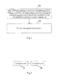
- Fig.1 is a schematic flow chart of a method for transmitting a downlink pilot according to an embodiment of the invention
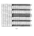
- Fig.2 is a schematic structural diagram of a device for transmitting a downlink pilot according to an embodiment of the invention
- Fig.3 illustrates a schematic structural diagram of LTE-A downlink dedicated pilots
- Fig.4 is a schematic diagram of a sub-carrier based sequence mapping scheme at the rank 3-rank 4 according to an embodiment of the invention
- Fig.5 is a schematic diagram of a sub-carrier group based sequence mapping scheme at the rank 3-rank 4 according to an embodiment of the invention
- Fig.6 is a schematic diagram of a sub-carrier based sequence mapping scheme at the rank 5-rank 8 according to an embodiment of the invention.
- Fig.7 is a schematic diagram of a sub-carrier group based sequence mapping scheme at the rank 5-rank 8 according to an embodiment of the invention.
- a dedicated pilot is transmitted in a Code Division Multiplexing (CDM) mode or in a hybrid CDM and Frequency Division Multiplexing (FDM) mode, where the dedicated pilot is configured with an orthogonal sequence over a resource for transmission of the dedicated pilot according to a preset mapping rule.
- CDM Code Division Multiplexing
- FDM Frequency Division Multiplexing
- a method for transmitting a dedicated pilot includes the following steps:
- Step 101 A dedicated pilot is mapped in a Code Division Multiplexing (CDM) mode or in a hybrid CDM and Frequency Division Multiplexing (FDM) mode, where the dedicated pilot is configured with an orthogonal sequence over a resource for transmission of the dedicated pilot according to a preset mapping rule, and furthermore the dedicated pilot can further be mapped to a port according to the preset mapping rule before it is configured with the orthogonal sequence.
- CDM Code Division Multiplexing
- FDM Frequency Division Multiplexing
- Step 102 The mapped dedicated pilot is transmitted.
- an orthogonal sequence and a mapping rule adopted for a first stream to be transmitted are the same as those at a transmission rank of 1 or 2, and an orthogonal sequence and a mapping rule adopted for a second stream to be transmitted are the same as those at a transmission rank of 2.
- an orthogonal sequence and a mapping rule adopted for a third stream to be transmitted are the same as those at a transmission rank of 3 or 4
- an orthogonal sequence and a mapping rule adopted for a fourth stream to be transmitted are the same as those at a transmission rank of 4.
- the same set of orthogonal sequences is adopted for groups of ports mapped into different resources; or groups of ports mapped into different resources are configured respectively with different sets of orthogonal sequences.
- the groups of ports mapped into different resources are configured respectively with the sets of orthogonal sequences between which a cyclic shift relationship is satisfied.
- the value of a cyclic shift is 2.
- Adjacent sub-carriers, of each port, for transmission of a dedicated pilot have their orthogonal sequences selected from different sets of orthogonal sequences.
- orthogonal sequences of adjacent sub-carriers, of each port, for transmission of a dedicated pilot are arranged in a reverse order to each other.
- two adjacent sub-carriers, corresponding to each port, for transmission of a dedicated pilot have their orthogonal sequences selected from different sets of orthogonal sequences;
- two adjacent sub-carriers, corresponding to each port, for transmission of a dedicated pilot have their orthogonal sequences selected from different sets of orthogonal sequences;
- two adjacent sub-carriers, corresponding to each port, for transmission of a dedicated pilot have their orthogonal sequences selected from different sets of orthogonal sequences in a frequency order within a system bandwidth;
- two adjacent sub-carriers, corresponding to each port, for transmission of a dedicated pilot have their orthogonal sequences selected from different sets of orthogonal sequences in a frequency order within a system bandwidth;
- four adjacent sub-carriers, corresponding to each port, for transmission of a dedicated pilot have their orthogonal sequences selected from different sets of orthogonal sequences in a frequency order within a system bandwidth.
- the number of sets of orthogonal sequences is consistent with the code length of an orthogonal code used for the dedicated pilot.
- a cyclic shift relationship is satisfied between the sets of orthogonal sequences.
- a device for transmitting a downlink pilot includes a configuring unit 21 and a transmitting unit 22, where:
- the configuring unit 21 is configured to configure a dedicated pilot with an orthogonal sequence over a resource for transmission of the dedicated pilot according to a preset mapping rule, and furthermore the configuring unit 21 can further map the dedicated pilot to a port according to the preset mapping rule before the dedicated pilot is configured with the orthogonal sequence.
- the transmitting unit 22 is configured to transmit the dedicated pilot in a Code Division Multiplexing (CDM) mode or in a hybrid CDM and Frequency Division Multiplexing (FDM) mode.
- CDM Code Division Multiplexing
- FDM Frequency Division Multiplexing
- an orthogonal sequence and a mapping rule adopted for a first stream are the same as those at a transmission rank of 1 or 2
- an orthogonal sequence and a mapping rule adopted for a second stream are the same as those at a transmission rank of 2.
- an orthogonal sequence and a mapping rule adopted for a third stream are the same as those at a transmission rank of 3 or 4, and an orthogonal sequence and a mapping rule adopted for a transmitted stream are the same as those at a transmission rank of 4.
- the same set of orthogonal sequences is adopted for groups of ports mapped into different resources; or groups of ports mapped into different resources are configured respectively with different sets of orthogonal sequences.
- groups of ports mapped into different resources are configured respectively with different sets of orthogonal sequences between which a cyclic shift relationship is satisfied.
- Preferably the value of a cyclic shift is 2.
- Adjacent sub-carriers, of each port, for transmission of a dedicated pilot have their orthogonal sequences selected from different sets of orthogonal sequences.
- orthogonal sequences of adjacent sub-carriers, of each port, for transmission of a dedicated pilot are arranged in a reverse order to each other.
- two adjacent sub-carriers, corresponding to each port, for transmission of a dedicated pilot have their orthogonal sequences selected from different sets of orthogonal sequences;
- two adjacent sub-carriers, corresponding to each port, for transmission of a dedicated pilot have their orthogonal sequences selected from different sets of orthogonal sequences; or for a system at a transmission rank of 5 to 8, four adjacent sub-carriers, corresponding to each port, for transmission of a dedicated pilot have their orthogonal sequences selected from different sets of orthogonal sequences
- two adjacent sub-carriers, corresponding to each port, for transmission of a dedicated pilot have their orthogonal sequences selected from different sets of orthogonal sequences in a frequency order within a system bandwidth;
- two adjacent sub-carriers, corresponding to each port, for transmission of a dedicated pilot have their orthogonal sequences selected from different sets of orthogonal sequences in a frequency order within a system bandwidth;
- four adjacent sub-carriers, corresponding to each port, for transmission of a dedicated pilot have their orthogonal sequences selected from different sets of orthogonal sequences in a frequency order within a system bandwidth.
- the number of sets of orthogonal sequences is consistent with the code length of an orthogonal code used for the dedicated pilot.
- a cyclic shift relationship is satisfied between the sets of orthogonal sequences.
- Fig.3 illustrates a structure of LTE-A downlink dedicated pilots.
- the structure of pilots at the rank3-rank4 is based upon that at the rank 1-rank2 but includes an increased number of support ports, and as illustrated in Fig.3 , 01 corresponds to first and second streams, and 23 corresponds to third and fourth streams; and 01 and 23 are distinguished from each other in a frequency division (FDM) mode, the first and second streams are distinguished from each other in a CDM mode, and the third and fourth streams are distinguished from each other in the CDM mode.
- FDM frequency division
- a set of orthogonal sequences is inverted (selected) particularly in two modes: sub-carrier based and sub-carrier group based.
- Fig.4 is a schematic diagram of an embodiment of sub-carrier based configuration of orthogonal sequences at the rank3-rank4. Referring to Fig.4 , there are different sets of orthogonal sequences for adjacent sub-carriers in this embodiment.
- An orthogonal sequence with a left-directed arrow is Code index0: [1 1] [1 -1];
- An orthogonal sequence with a light-directed arrow is Code index0: [1 1] [1 1].
- Fig.5 is a schematic diagram of another embodiment of sub-carrier group based configuration of orthogonal sequences at the rank3-rank4.
- firstly adjacent sub-carriers in a PRB are grouped into three groups in the PRB with two corresponding sub-carriers in a group; and a sequence is inverted (selected) per sub-carrier group, that is, the same set of orthogonal sequences is adopted for sub-carriers in a group, and different sets of orthogonal sequences are adopted for adjacent groups.
- An orthogonal sequence with a left-directed arrow is Code index0: [1 1] [1 -1];
- An orthogonal sequence with a right-directed arrow is Code index0: [1 1] [-1 1].
- 01 and 23 correspond to four streams respectively and are distinguished from each other in an FDM mode; and the four streams to which 01 correspond are distinguished from each other in a CDM mode, and the four streams to which 23 correspond are distinguished from each other in the CDM mode.
- a scheme can preferably be adopted that 01 corresponds to first, second, fifth and seventh streams, 23 corresponds to third, fourth, sixth and eighth streams, and 01 and 23 are distinguished from each other in a Frequency Division (FDM) mode.
- the first, second, fifth and seventh streams are distinguished from each other in a CDM mode, and the third, fourth, sixth and eighth streams are distinguished from each other in the CDM mode.
- This scheme is consistent and thus compatible with the scenario at the rank3-4 where 01 corresponds to the first and second streams and 23 corresponds to the third and fourth streams.
- a scheme in the scenario at the rank5-rank8 is the same as that at the rank3-rank4 with the length of an orthogonal sequence being 2 except for different ports to which respective sequences correspond, and a repeated description thereof will be omitted here.
- Fig.6 is a schematic diagram of a sub-carrier based sequence mapping scheme at the rank 5-rank8.
- similar or consistent power of respective pilot symbols can be ensured per sub-carrier.
- a cyclic shift relationship is satisfied between sets of orthogonal sequences configured respectively for groups of ports mapped into different resources, and sets of orthogonal sequences of adjacent sub-carriers, in the same group of ports, for transmission of dedicated pilots are arranged in a reverse order to each other, as depicted in Table 1 below: Table 1 Set 0 Set 1 Set 2 Set 3 Code 1 [1 1 1 1] [1 1 1 1] [1 1 1 1] [1 1 1 1] [1 1 1 1] [1 1 1 1] [-1 1 -1 1] [-1 1 -1 1] Code 3 [1 1 -1 -1] [-1 -1 1] [-1 -1 1] [1 1 -1 -1] Code 4 [1 -1 -1 1] [-1 1 1 -1] [1 1 1 -1] [1
- Fig.7 is a schematic diagram of a sub-carrier group based sequence mapping scheme at the rank 5-rank8. As illustrated in Fig.7 , similar or consistent power of respective pilot symbols can be ensured per sub-carrier group for sequences depicted in Table 2 below.
- a set of sequences is shifted cyclically to further create a new set of sequences, as depicted in Table 1 below:
- a power balance can be ensured, orthogonality in the time and frequency domains can be ensured and backward compatibility can be ensured for a design of orthogonal sequences at the rank3-rank8.
- a sequence mapping solution for streams 1 to 4 at the rank 8 can made consist completely with that at the rank 4. Therefore both backward compatibility and orthogonality in the time and frequency domains can be ensured in the embodiments of the invention.
Landscapes
- Engineering & Computer Science (AREA)
- Signal Processing (AREA)
- Computer Networks & Wireless Communication (AREA)
- Mobile Radio Communication Systems (AREA)
Abstract
Description
- The present invention relates to the field of communications and particularly to a method and device for transmitting a downlink pilot.
- In a 3GPP LTE-Advanced system (LTE stands for Long Term Evolution which is an evolved system of a third-generation mobile communication system, and an LTE-Advanced system is an upgraded LTE system), new technologies such as high-order MIMO, multi-cell coordinated transmission technology will be adopted to improve the performance of the system.
- In view of these new technical features, the LTE-A system adopts a dedicated pilot to demodulate data, and pilots are kept orthogonal between respective streams. For a transmission scheme with the number of streams being 1 and 2, pilots of two streams are orthogonal in a CDM mode; for a transmission scheme with the number of streams being 3 and 4, pilots of four streams are in a hybrid FDM and CDM mode; and for a transmission scheme with the number of streams being 5, 6, 7 and 8, pilots of eight streams are in the hybrid FDM and CDM mode. As can be seen, the CDM orthogonal mode is involved for pilots in all the transmission schemes. However a Walsh code or a normalized Walsh code is adopted as a pilot in the CDM mode, thus resulting in different power over two adjacent OFDM symbols where the pilot is located.
- Embodiments of the invention provide a method and device for transmitting a downlink pilot so as to address the problem in the prior art of different powers over OFDM symbols.
- An embodiment of the invention provides a method for transmitting a downlink pilot, which includes:
- transmitting a dedicated pilot in a Code Division Multiplexing, CDM, mode or in a hybrid CDM and Frequency Division Multiplexing, FDM, mode; and
- configuring the dedicated pilot with an orthogonal sequence over a resource for transmission of the dedicated pilot according to a preset mapping rule.
- An embodiment of the invention provides a device for transmitting a downlink pilot, which includes:
- a configuring unit configured to configure a dedicated pilot with an orthogonal sequence over a resource for transmission of the dedicated pilot according to a preset mapping rule; and
- a transmitting unit configured to transmit the dedicated pilot processed by the configuring unit in a Code Division Multiplexing, CDM, mode or in a hybrid CDM and Frequency Division Multiplexing, FDM, mode.
- In the embodiments of the invention, a dedicated pilot is transmitted in a Code Division Multiplexing (CDM) mode or in a hybrid CDM and Frequency Division Multiplexing (FDM) mode, where the dedicated pilot is configured with an orthogonal sequence over a resource for transmission of the dedicated pilot according to a preset mapping rule to thereby address the problem of different power of OFDM symbols due to a Walsh code.
-
Fig.1 is a schematic flow chart of a method for transmitting a downlink pilot according to an embodiment of the invention; -
Fig.2 is a schematic structural diagram of a device for transmitting a downlink pilot according to an embodiment of the invention; -
Fig.3 illustrates a schematic structural diagram of LTE-A downlink dedicated pilots; -
Fig.4 is a schematic diagram of a sub-carrier based sequence mapping scheme at the rank 3-rank 4 according to an embodiment of the invention; -
Fig.5 is a schematic diagram of a sub-carrier group based sequence mapping scheme at the rank 3-rank 4 according to an embodiment of the invention; -
Fig.6 is a schematic diagram of a sub-carrier based sequence mapping scheme at the rank 5-rank 8 according to an embodiment of the invention; and -
Fig.7 is a schematic diagram of a sub-carrier group based sequence mapping scheme at the rank 5-rank 8 according to an embodiment of the invention. - In embodiments of the invention, a dedicated pilot is transmitted in a Code Division Multiplexing (CDM) mode or in a hybrid CDM and Frequency Division Multiplexing (FDM) mode, where the dedicated pilot is configured with an orthogonal sequence over a resource for transmission of the dedicated pilot according to a preset mapping rule.
- Referring to
Fig.1 , a method for transmitting a dedicated pilot according to an embodiment of the invention includes the following steps: - Step 101: A dedicated pilot is mapped in a Code Division Multiplexing (CDM) mode or in a hybrid CDM and Frequency Division Multiplexing (FDM) mode, where the dedicated pilot is configured with an orthogonal sequence over a resource for transmission of the dedicated pilot according to a preset mapping rule, and furthermore the dedicated pilot can further be mapped to a port according to the preset mapping rule before it is configured with the orthogonal sequence.
- Step 102: The mapped dedicated pilot is transmitted.
- For a system at a transmission rank of 3 to 8, an orthogonal sequence and a mapping rule adopted for a first stream to be transmitted are the same as those at a transmission rank of 1 or 2, and an orthogonal sequence and a mapping rule adopted for a second stream to be transmitted are the same as those at a transmission rank of 2. For a system at a transmission rank of 5 to 8, an orthogonal sequence and a mapping rule adopted for a third stream to be transmitted are the same as those at a transmission rank of 3 or 4, and an orthogonal sequence and a mapping rule adopted for a fourth stream to be transmitted are the same as those at a transmission rank of 4.
- The same set of orthogonal sequences is adopted for groups of ports mapped into different resources; or groups of ports mapped into different resources are configured respectively with different sets of orthogonal sequences.
- In a recommended design, the groups of ports mapped into different resources are configured respectively with the sets of orthogonal sequences between which a cyclic shift relationship is satisfied. Preferably the value of a cyclic shift is 2.
- Different orthogonal sequences in the same set of orthogonal sequences are adopted for ports mapped onto the same sub-carrier.
- Adjacent sub-carriers, of each port, for transmission of a dedicated pilot have their orthogonal sequences selected from different sets of orthogonal sequences. In a recommended design, orthogonal sequences of adjacent sub-carriers, of each port, for transmission of a dedicated pilot are arranged in a reverse order to each other.
- For a system at a transmission rank of 1 to 4, two adjacent sub-carriers, corresponding to each port, for transmission of a dedicated pilot have their orthogonal sequences selected from different sets of orthogonal sequences;
- For a system at a transmission rank of 5 to 8, two adjacent sub-carriers, corresponding to each port, for transmission of a dedicated pilot have their orthogonal sequences selected from different sets of orthogonal sequences; or
- For a system at a transmission rank of 5 to 8, four adjacent sub-carriers, corresponding to each port, for transmission of a dedicated pilot have their orthogonal sequences selected from different sets of orthogonal sequences
- For a system at a transmission rank of 1 to 4, two adjacent sub-carriers, corresponding to each port, for transmission of a dedicated pilot have their orthogonal sequences selected from different sets of orthogonal sequences in a frequency order within a system bandwidth;
- For a system at a transmission rank of 5 to 8, two adjacent sub-carriers, corresponding to each port, for transmission of a dedicated pilot have their orthogonal sequences selected from different sets of orthogonal sequences in a frequency order within a system bandwidth; or
- For a system at a transmission rank of 5 to 8, four adjacent sub-carriers, corresponding to each port, for transmission of a dedicated pilot have their orthogonal sequences selected from different sets of orthogonal sequences in a frequency order within a system bandwidth.
- The number of sets of orthogonal sequences is consistent with the code length of an orthogonal code used for the dedicated pilot.
- A cyclic shift relationship is satisfied between the sets of orthogonal sequences.
- Referring to
Fig.2 , a device for transmitting a downlink pilot according to an embodiment of the invention includes a configuringunit 21 and a transmittingunit 22, where: - The configuring
unit 21 is configured to configure a dedicated pilot with an orthogonal sequence over a resource for transmission of the dedicated pilot according to a preset mapping rule, and furthermore the configuringunit 21 can further map the dedicated pilot to a port according to the preset mapping rule before the dedicated pilot is configured with the orthogonal sequence. - The transmitting
unit 22 is configured to transmit the dedicated pilot in a Code Division Multiplexing (CDM) mode or in a hybrid CDM and Frequency Division Multiplexing (FDM) mode. - For a system at a transmission rank of 3 to 8, an orthogonal sequence and a mapping rule adopted for a first stream are the same as those at a transmission rank of 1 or 2, and an orthogonal sequence and a mapping rule adopted for a second stream are the same as those at a transmission rank of 2.
- For a system at a transmission rank of 5 to 8, an orthogonal sequence and a mapping rule adopted for a third stream are the same as those at a transmission rank of 3 or 4, and an orthogonal sequence and a mapping rule adopted for a transmitted stream are the same as those at a transmission rank of 4.
- The same set of orthogonal sequences is adopted for groups of ports mapped into different resources; or groups of ports mapped into different resources are configured respectively with different sets of orthogonal sequences.
- In a recommended design, groups of ports mapped into different resources are configured respectively with different sets of orthogonal sequences between which a cyclic shift relationship is satisfied. Preferably the value of a cyclic shift is 2.
- Different orthogonal sequences in the same set of orthogonal sequences are adopted for ports mapped onto the same sub-carrier.
- Adjacent sub-carriers, of each port, for transmission of a dedicated pilot have their orthogonal sequences selected from different sets of orthogonal sequences. In a recommended design, orthogonal sequences of adjacent sub-carriers, of each port, for transmission of a dedicated pilot are arranged in a reverse order to each other.
- For a system at a transmission rank of 1 to 4, two adjacent sub-carriers, corresponding to each port, for transmission of a dedicated pilot have their orthogonal sequences selected from different sets of orthogonal sequences; for a system at a transmission rank of 5 to 8, two adjacent sub-carriers, corresponding to each port, for transmission of a dedicated pilot have their orthogonal sequences selected from different sets of orthogonal sequences; or for a system at a transmission rank of 5 to 8, four adjacent sub-carriers, corresponding to each port, for transmission of a dedicated pilot have their orthogonal sequences selected from different sets of orthogonal sequences
- For a system at a transmission rank of 1 to 4, two adjacent sub-carriers, corresponding to each port, for transmission of a dedicated pilot have their orthogonal sequences selected from different sets of orthogonal sequences in a frequency order within a system bandwidth;
- For a system at a transmission rank of 5 to 8, two adjacent sub-carriers, corresponding to each port, for transmission of a dedicated pilot have their orthogonal sequences selected from different sets of orthogonal sequences in a frequency order within a system bandwidth; or
- For a system at a transmission rank of 5 to 8, four adjacent sub-carriers, corresponding to each port, for transmission of a dedicated pilot have their orthogonal sequences selected from different sets of orthogonal sequences in a frequency order within a system bandwidth.
- The number of sets of orthogonal sequences is consistent with the code length of an orthogonal code used for the dedicated pilot.
- A cyclic shift relationship is satisfied between the sets of orthogonal sequences.
- A specific implementation solution at the rank3-rank4 will be detailed below in particular embodiments.
-
Fig.3 illustrates a structure of LTE-A downlink dedicated pilots. Referring toFig.3 , the structure of pilots at the rank3-rank4 is based upon that at the rank 1-rank2 but includes an increased number of support ports, and as illustrated inFig.3 ,01 corresponds to first and second streams, and 23 corresponds to third and fourth streams; and 01 and 23 are distinguished from each other in a frequency division (FDM) mode, the first and second streams are distinguished from each other in a CDM mode, and the third and fourth streams are distinguished from each other in the CDM mode. - In view of the structural characteristic of the dedicated pilots at the rank3-rank4, a set of orthogonal sequences is inverted (selected) particularly in two modes: sub-carrier based and sub-carrier group based.
-
Fig.4 is a schematic diagram of an embodiment of sub-carrier based configuration of orthogonal sequences at the rank3-rank4. Referring toFig.4 , there are different sets of orthogonal sequences for adjacent sub-carriers in this embodiment. - An orthogonal sequence with a left-directed arrowis Code index0: [1 1] [1 -1]; and

- An orthogonal sequence with a light-directed arrowis Code index0: [1 1] [1 1].

-
Fig.5 is a schematic diagram of another embodiment of sub-carrier group based configuration of orthogonal sequences at the rank3-rank4. Referring toFig.5 , in this embodiment, firstly adjacent sub-carriers in a PRB are grouped into three groups in the PRB with two corresponding sub-carriers in a group; and a sequence is inverted (selected) per sub-carrier group, that is, the same set of orthogonal sequences is adopted for sub-carriers in a group, and different sets of orthogonal sequences are adopted for adjacent groups. - An orthogonal sequence with a left-directed arrowis Code index0: [1 1] [1 -1]; and

- An orthogonal sequence with a right-directed arrowis Code index0: [1 1] [-1 1].

- A specific implementation solution at the rank5-rank8 will be detailed below in particular embodiments.
- Referring to
Fig.3 , in a port mapping scheme, 01 and 23 correspond to four streams respectively and are distinguished from each other in an FDM mode; and the four streams to which 01 correspond are distinguished from each other in a CDM mode, and the four streams to which 23 correspond are distinguished from each other in the CDM mode. For backward compatibility, such a scheme can preferably be adopted that 01 corresponds to first, second, fifth and seventh streams, 23 corresponds to third, fourth, sixth and eighth streams, and 01 and 23 are distinguished from each other in a Frequency Division (FDM) mode. The first, second, fifth and seventh streams are distinguished from each other in a CDM mode, and the third, fourth, sixth and eighth streams are distinguished from each other in the CDM mode. This scheme is consistent and thus compatible with the scenario at the rank3-4 where 01 corresponds to the first and second streams and 23 corresponds to the third and fourth streams. - A scheme in the scenario at the rank5-rank8 is the same as that at the rank3-rank4 with the length of an orthogonal sequence being 2 except for different ports to which respective sequences correspond, and a repeated description thereof will be omitted here.
- Four sets of orthogonal sequences are adopted and mapped according to a predetermined rule in the scenario at the rank5-rank8 with the length of an orthogonal sequence being 4.
-
Fig.6 is a schematic diagram of a sub-carrier based sequence mapping scheme at the rank 5-rank8. In this embodiment, similar or consistent power of respective pilot symbols can be ensured per sub-carrier. In a recommended design, a cyclic shift relationship is satisfied between sets of orthogonal sequences configured respectively for groups of ports mapped into different resources, and sets of orthogonal sequences of adjacent sub-carriers, in the same group of ports, for transmission of dedicated pilots are arranged in a reverse order to each other, as depicted in Table 1 below:Table 1 Set 0 Set 1 Set 2 Set 3 Code 1 [1 1 1 1] [1 1 1 1] [1 1 1 1] [1 1 1 1] Code 2 [1 -1 1 -1] [1 -1 1 -1] [-1 1 -1 1] [-1 1 -1 1] Code 3 [1 1 -1 -1] [-1 -1 1 1] [-1 -1 1 1] [1 1 -1 -1] Code 4 [1 -1 -1 1] [-1 1 1 -1] [1 - 1 -1 1] [-1 1 1 -1] - For backward compatibility, that is, full consistency of a sequence mapping solution for streams 1 to 4 at the rank 8 with that at the rank 4, the mapping scheme of
Fig.6 is recommended. -
Fig.7 is a schematic diagram of a sub-carrier group based sequence mapping scheme at the rank 5-rank8. As illustrated inFig.7 , similar or consistent power of respective pilot symbols can be ensured per sub-carrier group for sequences depicted in Table 2 below. In a recommended design, a set of sequences is shifted cyclically to further create a new set of sequences, as depicted in Table 1 below:Table 2 Set 0 Set 1 Set 2 Set 3 Code 1 [1 1 1 1] [1 1 1 1] [1 1 1 1] [1 1 1 1] Code 2 [1 -1 1 -1] [-1 1 -1 1] [-1 1 -1 1] [1 -1 1 -1] Code 3 [1 -1 -1 1] [-1 -1 1 1] [1 1 1 -1 -1] [-1 1 1 -1] Code 4 [1 1 -1 -1] [1 -1 -1 1] [-1 1 1 -1] [-1 -1 1 1] - In the embodiments of the invention, a power balance can be ensured, orthogonality in the time and frequency domains can be ensured and backward compatibility can be ensured for a design of orthogonal sequences at the rank3-rank8. Furthermore a sequence mapping solution for streams 1 to 4 at the rank 8 can made consist completely with that at the rank 4. Therefore both backward compatibility and orthogonality in the time and frequency domains can be ensured in the embodiments of the invention.
- Evidently those skilled in the art can make various modifications and variations to the invention without departing from the spirit and the scope of the invention. Thus the invention is also intended to encompass these modifications and variations thereto as long as these modifications and variations come into the scope of the claims appended to the invention and their equivalents.
Claims (26)
- A method for transmitting a dedicated pilot, comprising the steps of:transmitting a dedicated pilot in a Code Division Multiplexing, CDM, mode or in a hybrid CDM and Frequency Division Multiplexing, FDM, mode; andconfiguring the dedicated pilot with an orthogonal sequence over a resource for transmission of the dedicated pilot according to a preset mapping rule.
- The method according to claim 1, wherein for a system at a transmission rank of 3 to 8, an orthogonal sequence and a mapping rule adopted for a first stream to be transmitted are the same as those at a transmission rank of 1 or 2, and an orthogonal sequence and a mapping rule adopted for a second stream to be transmitted are the same as those at a transmission rank of 2.
- The method according to claim 1, wherein for a system at a transmission rank of 5 to 8, an orthogonal sequence and a mapping rule adopted for a third stream to be transmitted are the same as those at a transmission rank of 3 or 4, and an orthogonal sequence and a mapping rule adopted for a fourth stream to be transmitted are the same as those at a transmission rank of 4.
- The method according to claim 1, wherein the same set of orthogonal sequences is adopted for groups of ports mapped into different resources; or
groups of ports mapped into different resources are configured respectively with different sets of orthogonal sequences. - The method according to claim 4, wherein the groups of ports mapped into the different resources are configured respectively with different sets of orthogonal sequences between which a cyclic shift relationship is satisfied.
- The method according to claim 5, wherein the value of a cyclic shift is 2.
- The method according to claim 1, wherein different orthogonal sequences in the same set of orthogonal sequences are adopted for ports mapped onto the same sub-carrier.
- The method according to claim 1, wherein adjacent sub-carriers, of each port, for transmission of the dedicated pilot have their orthogonal sequences selected from different sets of orthogonal sequences.
- The method according to claim 8, wherein:for a system at a transmission rank of 1 to 4, two adjacent sub-carriers, corresponding to each port, for transmission of the dedicated pilot have their orthogonal sequences selected from different sets of orthogonal sequences;for a system at a transmission rank of 5 to 8, two adjacent sub-carriers, corresponding to each port, for transmission of the dedicated pilot have their orthogonal sequences selected from different sets of orthogonal sequences; orfor a system at the transmission rank of 5 to 8, four adjacent sub-carriers, corresponding to each port, for transmission of the dedicated pilot have their orthogonal sequences selected from different sets of orthogonal sequences.
- The method according to claim 9, wherein for a system at the transmission rank of 1 to 4, two adjacent sub-carriers, corresponding to each port, for transmission of the dedicated pilot have their orthogonal sequences selected from different sets of orthogonal sequences in a frequency order within a system bandwidth;
for a system at the transmission rank of 5 to 8, two adjacent sub-carriers, corresponding to each port, for transmission of the dedicated pilot have their orthogonal sequences selected from different sets of orthogonal sequences in a frequency order within a system bandwidth; or
for a system at the transmission rank of 5 to 8, four adjacent sub-carriers, corresponding to each port, for transmission of the dedicated pilot have their orthogonal sequences selected from different sets of orthogonal sequences in a frequency order within a system bandwidth. - The method according to claim 6, wherein the different sets of orthogonal sequences are arranged in a reverse order to each other.
- The method according to claim 7 or 8, wherein the number of sets of orthogonal sequences is consistent with the code length of an orthogonal code used for the dedicated pilot.
- The method according to claim 7 or 8, wherein a cyclic shift relationship is satisfied between the sets of orthogonal sequences.
- A device for transmitting a dedicated pilot, comprising:a configuring unit configured to configure a dedicated pilot with an orthogonal sequence over a resource for transmission of the dedicated pilot according to a preset mapping rule; anda transmitting unit configured to transmit the dedicated pilot processed by the configuring unit in a Code Division Multiplexing, CDM, mode or in a hybrid CDM and Frequency Division Multiplexing, FDM, mode.
- The device according to claim 14, wherein for a system at a transmission rank of 3 to 8, an orthogonal sequence and a mapping rule adopted for a first stream are the same as those at a transmission rank of 1 or 2, and an orthogonal sequence and a mapping rule adopted for a second stream are the same as those at a transmission rank of 2.
- The device according to claim 14, wherein for a system at a transmission rank of 5 to 8, an orthogonal sequence and a mapping rule adopted for a third stream are the same as those at a transmission rank of 3 or 4, and an orthogonal sequence and a mapping rule adopted for a fourth stream are the same as those at a transmission rank of 4.
- The device according to claim 14, wherein the same set of orthogonal sequences is adopted for groups of ports mapped into different resources; or groups of ports mapped into different resources are configured respectively with different sets of orthogonal sequences.
- The device according to claim 17, wherein the groups of ports mapped into the different resources are configured respectively with sets of orthogonal sequences between which a cyclic shift relationship is satisfied.
- The device according to claim 18, wherein the value of a cyclic shift is 2.
- The device according to claim 14, wherein different orthogonal sequences in the same set of orthogonal sequences are adopted for ports mapped onto the same sub-carrier.
- The device according to claim 14, wherein adjacent sub-carriers, of each port, for transmission of the dedicated pilot have their orthogonal sequences selected from different sets of orthogonal sequences.
- The device according to claim 21, wherein for a system at a transmission rank of 1 to 4, two adjacent sub-carriers, corresponding to each port, for transmission of the dedicated pilot have their orthogonal sequences selected from different sets of orthogonal sequences; for a system at a transmission rank of 5 to 8, two adjacent sub-carriers, corresponding to each port, for transmission of the dedicated pilot have their orthogonal sequences selected from different sets of orthogonal sequences; or for a system at the transmission rank of 5 to 8, four adjacent sub-carriers, corresponding to each port, for transmission of the dedicated pilot have their orthogonal sequences selected from different sets of orthogonal sequences.
- The device according to claim 22, wherein for a system at the transmission rank of 1 to 4, two adjacent sub-carriers, corresponding to each port, for transmission of the dedicated pilot have their orthogonal sequences selected from different sets of orthogonal sequences in a frequency order within a system bandwidth;
for a system at the transmission rank of 5 to 8, two adjacent sub-carriers, corresponding to each port, for transmission of the dedicated pilot have their orthogonal sequences selected from different sets of orthogonal sequences in a frequency order within a system bandwidth; or
for a system at the transmission rank of 5 to 8, four adjacent sub-carriers, corresponding to each port, for transmission of the dedicated pilot have their orthogonal sequences selected from different sets of orthogonal sequences. - The device according to claim 21, wherein the different sets of orthogonal sequences are arranged in a reverse order to each other.
- The device according to claim 20 or 21, wherein the number of sets of orthogonal sequences is consistent with the code length of an orthogonal code used for the dedicated pilot.
- The device according to claim 20 or 21, wherein a cyclic shift relationship is satisfied between the sets of orthogonal sequences.
Applications Claiming Priority (2)
| Application Number | Priority Date | Filing Date | Title |
|---|---|---|---|
| CN201010002542.4A CN102082755B (en) | 2010-01-11 | 2010-01-11 | The transmission method of a kind of descending pilot frequency, device |
| PCT/CN2011/070149 WO2011082697A1 (en) | 2010-01-11 | 2011-01-11 | Method and apparatus for transmitting downlink pilot |
Publications (2)
| Publication Number | Publication Date |
|---|---|
| EP2525540A1 true EP2525540A1 (en) | 2012-11-21 |
| EP2525540A4 EP2525540A4 (en) | 2013-10-16 |
Family
ID=44088509
Family Applications (1)
| Application Number | Title | Priority Date | Filing Date |
|---|---|---|---|
| EP11731698.4A Withdrawn EP2525540A4 (en) | 2010-01-11 | 2011-01-11 | Method and apparatus for transmitting downlink pilot |
Country Status (4)
| Country | Link |
|---|---|
| US (1) | US9780935B2 (en) |
| EP (1) | EP2525540A4 (en) |
| CN (1) | CN102082755B (en) |
| WO (1) | WO2011082697A1 (en) |
Families Citing this family (1)
| Publication number | Priority date | Publication date | Assignee | Title |
|---|---|---|---|---|
| JP5793184B2 (en) * | 2011-04-26 | 2015-10-14 | パナソニック インテレクチュアル プロパティ コーポレーション オブアメリカPanasonic Intellectual Property Corporation of America | Transmitting device, receiving device, transmitting method, receiving method |
Family Cites Families (12)
| Publication number | Priority date | Publication date | Assignee | Title |
|---|---|---|---|---|
| US7848438B2 (en) * | 2006-02-14 | 2010-12-07 | Motorola Mobility, Inc. | Method and apparatus for pilot signal transmission |
| US8064394B2 (en) * | 2007-02-14 | 2011-11-22 | Telefonaktiebolaget L M Ericsson | Methods and systems for codeword to layer mapping |
| US8369299B2 (en) * | 2007-05-07 | 2013-02-05 | Qualcomm Incorporated | Method and apparatus for multiplexing CDM pilot and FDM data |
| KR101548324B1 (en) * | 2007-08-08 | 2015-09-07 | 한국전자통신연구원 | Method and apparatus for signal formation in a wireless communication system |
| CN101409583B (en) * | 2007-10-11 | 2013-02-13 | 电信科学技术研究院 | Method and device for transmitting signal |
| US20090168730A1 (en) * | 2007-10-29 | 2009-07-02 | Motorola, Inc. | Pilot Signal Allocation Method and Apparatus |
| CN101431490A (en) * | 2007-10-30 | 2009-05-13 | 大唐移动通信设备有限公司 | Pilot frequency insertion method, apparatus, base station and customer equipment of orthogonal frequency division multiplexing system |
| KR101468226B1 (en) * | 2008-03-19 | 2014-12-04 | 엘지전자 주식회사 | Method for generating a preamble for random access in a wireless communication system |
| EP3197077B1 (en) * | 2008-10-30 | 2019-12-04 | Sun Patent Trust | Radio communication device and radio communication method |
| KR101559794B1 (en) * | 2009-02-17 | 2015-10-13 | 엘지전자 주식회사 | Method for sequence generaton and apparatus therefor |
| WO2011046349A2 (en) * | 2009-10-12 | 2011-04-21 | 엘지전자 주식회사 | Method and apparatus for providing downlink reference signal transmission power information in a wireless communication system that supports multiple antennas |
| WO2012067448A2 (en) * | 2010-11-17 | 2012-05-24 | 엘지전자 주식회사 | Method and apparatus for transceiving a downlink control channel in a wireless communication system |
-
2010
- 2010-01-11 CN CN201010002542.4A patent/CN102082755B/en active Active
-
2011
- 2011-01-11 US US13/521,659 patent/US9780935B2/en active Active
- 2011-01-11 WO PCT/CN2011/070149 patent/WO2011082697A1/en not_active Ceased
- 2011-01-11 EP EP11731698.4A patent/EP2525540A4/en not_active Withdrawn
Non-Patent Citations (4)
| Title |
|---|
| ERICSSON ET AL: "On Rel-10 DM RS design for rank 5-8", 3GPP DRAFT; R1-094438 ON REL-10 DM RS DESIGN FOR RANK 5-8, 3RD GENERATION PARTNERSHIP PROJECT (3GPP), MOBILE COMPETENCE CENTRE ; 650, ROUTE DES LUCIOLES ; F-06921 SOPHIA-ANTIPOLIS CEDEX ; FRANCE, no. Jeju; 20091109, 9 November 2009 (2009-11-09), XP050388866, [retrieved on 2009-11-03] * |
| PANASONIC: "Joint consideration of DL DM-RS design and codeword-layer mapping for rank over 3", 3GPP DRAFT; R1-094507, 3RD GENERATION PARTNERSHIP PROJECT (3GPP), MOBILE COMPETENCE CENTRE ; 650, ROUTE DES LUCIOLES ; F-06921 SOPHIA-ANTIPOLIS CEDEX ; FRANCE, no. Jeju; 20091109, 9 November 2009 (2009-11-09), XP050388927, [retrieved on 2009-11-02] * |
| RESEARCH IN MOTION ET AL: "Downlink DM-RS Design Considerations for Rank 5-8 in LTE-A", 3GPP DRAFT; R1-094454(RIM-DL_DM-RS RANK 5-8), 3RD GENERATION PARTNERSHIP PROJECT (3GPP), MOBILE COMPETENCE CENTRE ; 650, ROUTE DES LUCIOLES ; F-06921 SOPHIA-ANTIPOLIS CEDEX ; FRANCE, no. Jeju; 20091109, 9 November 2009 (2009-11-09), XP050388880, [retrieved on 2009-11-03] * |
| See also references of WO2011082697A1 * |
Also Published As
| Publication number | Publication date |
|---|---|
| WO2011082697A1 (en) | 2011-07-14 |
| CN102082755A (en) | 2011-06-01 |
| EP2525540A4 (en) | 2013-10-16 |
| US20130016674A1 (en) | 2013-01-17 |
| CN102082755B (en) | 2016-06-08 |
| US9780935B2 (en) | 2017-10-03 |
Similar Documents
| Publication | Publication Date | Title |
|---|---|---|
| CN102469059B (en) | Demodulated reference signal bearing method and device | |
| KR101700003B1 (en) | Antenna port mapping method and device for demodulation reference signals | |
| JP2025131739A (en) | Signaling aspects for indicating cooperatively scheduled DMRS ports in MU-MIMO | |
| CN102577156B (en) | For sending method and the device of downlink reference signal | |
| KR101280984B1 (en) | Insertion of downlink demodulation reference signals into ofdm frames | |
| CN102299757B (en) | Method for allocating reference signal template and related communication device | |
| EP2775653A1 (en) | Systems and methods for bundling resource blocks in a wireless communication system | |
| KR102711905B1 (en) | Method and apparatus for transmitting and receiving demodulation reference signal pattern configuration information for nr system | |
| WO2019137311A1 (en) | Resource grid offset indication in mixed numerologies | |
| CN103581094B (en) | The transmission method of downlink user dedicated demodulation reference signal and equipment | |
| JP7043600B2 (en) | Methods and equipment for information instruction and resource determination as well as computer storage media | |
| CN104798330B (en) | Transmit the control information transferring method and this transmission receiving point, the control message receiving method of terminal and this terminal of receiving point | |
| CN102598568A (en) | Downlink control signalling for downlink mimo | |
| KR20140042892A (en) | Control channel receiving and sending method and device | |
| WO2013020491A1 (en) | Pilot signal sending method and device | |
| CN103248469A (en) | Method and system for sending and detecting control signaling and demodulated pilot frequency, and base station | |
| CN106961316B (en) | Transmission method and equipment for physical uplink shared channel in LTE-A Pro | |
| CN104718715A (en) | Transmission and reception of control information | |
| US9780935B2 (en) | Method and device for transmitting downlink pilot | |
| KR101574713B1 (en) | Method for transmitting control information, transmission/reception point thereof, method for receiving control information and terminal thereof | |
| JP6027637B2 (en) | Antenna port mapping method and apparatus for demodulated reference signal | |
| KR20160121321A (en) | Method and Apparatus for Configuring DM-RS for FD-MIMO Environment | |
| KR20170067837A (en) | Method and apparatus for allocating resource for dm-rs, and communication system | |
| CN102215197A (en) | Channel measurement pilot frequency mapping method and base station |
Legal Events
| Date | Code | Title | Description |
|---|---|---|---|
| PUAI | Public reference made under article 153(3) epc to a published international application that has entered the european phase |
Free format text: ORIGINAL CODE: 0009012 |
|
| 17P | Request for examination filed |
Effective date: 20120813 |
|
| AK | Designated contracting states |
Kind code of ref document: A1 Designated state(s): AL AT BE BG CH CY CZ DE DK EE ES FI FR GB GR HR HU IE IS IT LI LT LU LV MC MK MT NL NO PL PT RO RS SE SI SK SM TR |
|
| DAX | Request for extension of the european patent (deleted) | ||
| A4 | Supplementary search report drawn up and despatched |
Effective date: 20130916 |
|
| RIC1 | Information provided on ipc code assigned before grant |
Ipc: H04J 13/16 20110101ALI20130910BHEP Ipc: H04L 25/03 20060101ALN20130910BHEP Ipc: H04B 7/06 20060101ALI20130910BHEP Ipc: H04L 5/00 20060101ALN20130910BHEP Ipc: H04J 13/00 20110101ALN20130910BHEP Ipc: H04L 27/26 20060101AFI20130910BHEP |
|
| 17Q | First examination report despatched |
Effective date: 20131029 |
|
| STAA | Information on the status of an ep patent application or granted ep patent |
Free format text: STATUS: EXAMINATION IS IN PROGRESS |
|
| STAA | Information on the status of an ep patent application or granted ep patent |
Free format text: STATUS: THE APPLICATION HAS BEEN WITHDRAWN |
|
| 18W | Application withdrawn |
Effective date: 20171123 |