EP2525158A2 - Outdoor unit for air conditioner - Google Patents
Outdoor unit for air conditioner Download PDFInfo
- Publication number
- EP2525158A2 EP2525158A2 EP12168014A EP12168014A EP2525158A2 EP 2525158 A2 EP2525158 A2 EP 2525158A2 EP 12168014 A EP12168014 A EP 12168014A EP 12168014 A EP12168014 A EP 12168014A EP 2525158 A2 EP2525158 A2 EP 2525158A2
- Authority
- EP
- European Patent Office
- Prior art keywords
- partition plate
- plate
- heat exchange
- machine chamber
- outdoor unit
- Prior art date
- Legal status (The legal status is an assumption and is not a legal conclusion. Google has not performed a legal analysis and makes no representation as to the accuracy of the status listed.)
- Withdrawn
Links
- 238000005192 partition Methods 0.000 claims abstract description 168
- XLYOFNOQVPJJNP-UHFFFAOYSA-N water Substances O XLYOFNOQVPJJNP-UHFFFAOYSA-N 0.000 claims abstract description 83
- 230000008595 infiltration Effects 0.000 claims description 42
- 238000001764 infiltration Methods 0.000 claims description 42
- 238000005452 bending Methods 0.000 claims description 18
- 230000005855 radiation Effects 0.000 claims description 7
- 238000004804 winding Methods 0.000 claims description 4
- 238000012546 transfer Methods 0.000 claims description 3
- 238000012423 maintenance Methods 0.000 description 16
- 238000010276 construction Methods 0.000 description 14
- 239000003507 refrigerant Substances 0.000 description 12
- 229910052751 metal Inorganic materials 0.000 description 11
- 239000002184 metal Substances 0.000 description 11
- 238000009423 ventilation Methods 0.000 description 6
- 230000020169 heat generation Effects 0.000 description 5
- 239000003990 capacitor Substances 0.000 description 4
- 238000001816 cooling Methods 0.000 description 4
- 239000007788 liquid Substances 0.000 description 3
- 238000012545 processing Methods 0.000 description 3
- 238000004891 communication Methods 0.000 description 2
- 238000010438 heat treatment Methods 0.000 description 2
- 238000007654 immersion Methods 0.000 description 2
- 238000012856 packing Methods 0.000 description 2
- 239000011347 resin Substances 0.000 description 2
- 229920005989 resin Polymers 0.000 description 2
- 229910052782 aluminium Inorganic materials 0.000 description 1
- XAGFODPZIPBFFR-UHFFFAOYSA-N aluminium Chemical compound [Al] XAGFODPZIPBFFR-UHFFFAOYSA-N 0.000 description 1
- 230000000903 blocking effect Effects 0.000 description 1
- 238000007664 blowing Methods 0.000 description 1
- 238000000034 method Methods 0.000 description 1
- 238000000465 moulding Methods 0.000 description 1
- 238000000638 solvent extraction Methods 0.000 description 1
Images




Classifications
-
- F—MECHANICAL ENGINEERING; LIGHTING; HEATING; WEAPONS; BLASTING
- F24—HEATING; RANGES; VENTILATING
- F24F—AIR-CONDITIONING; AIR-HUMIDIFICATION; VENTILATION; USE OF AIR CURRENTS FOR SCREENING
- F24F1/00—Room units for air-conditioning, e.g. separate or self-contained units or units receiving primary air from a central station
- F24F1/06—Separate outdoor units, e.g. outdoor unit to be linked to a separate room comprising a compressor and a heat exchanger
- F24F1/20—Electric components for separate outdoor units
- F24F1/24—Cooling of electric components
-
- F—MECHANICAL ENGINEERING; LIGHTING; HEATING; WEAPONS; BLASTING
- F24—HEATING; RANGES; VENTILATING
- F24F—AIR-CONDITIONING; AIR-HUMIDIFICATION; VENTILATION; USE OF AIR CURRENTS FOR SCREENING
- F24F1/00—Room units for air-conditioning, e.g. separate or self-contained units or units receiving primary air from a central station
- F24F1/06—Separate outdoor units, e.g. outdoor unit to be linked to a separate room comprising a compressor and a heat exchanger
- F24F1/20—Electric components for separate outdoor units
- F24F1/22—Arrangement or mounting thereof
-
- F—MECHANICAL ENGINEERING; LIGHTING; HEATING; WEAPONS; BLASTING
- F24—HEATING; RANGES; VENTILATING
- F24F—AIR-CONDITIONING; AIR-HUMIDIFICATION; VENTILATION; USE OF AIR CURRENTS FOR SCREENING
- F24F1/00—Room units for air-conditioning, e.g. separate or self-contained units or units receiving primary air from a central station
- F24F1/06—Separate outdoor units, e.g. outdoor unit to be linked to a separate room comprising a compressor and a heat exchanger
- F24F1/46—Component arrangements in separate outdoor units
-
- F—MECHANICAL ENGINEERING; LIGHTING; HEATING; WEAPONS; BLASTING
- F24—HEATING; RANGES; VENTILATING
- F24F—AIR-CONDITIONING; AIR-HUMIDIFICATION; VENTILATION; USE OF AIR CURRENTS FOR SCREENING
- F24F1/00—Room units for air-conditioning, e.g. separate or self-contained units or units receiving primary air from a central station
- F24F1/06—Separate outdoor units, e.g. outdoor unit to be linked to a separate room comprising a compressor and a heat exchanger
- F24F1/56—Casing or covers of separate outdoor units, e.g. fan guards
- F24F1/58—Separate protective covers for outdoor units, e.g. solar guards, snow shields or camouflage
Definitions
- the present invention relates to an outdoor unit for an air conditioner.
- an outdoor unit for an air conditioner in which the inside of a housing is partitioned into a heat exchange chamber and a machine chamber through a partition plate erected from a bottom plate and a heat exchanger and an air blower are mounted in the heat exchange chamber while a compressor and an electric component mount unit are mounted in the machine chamber.
- a heat sink for radiating heat generated from electrical components mounted in the electrical component mount unit is joined to the electrical component mount unit.
- An opening portion through which the heat exchange chamber and the machine chamber are continuous with each other is provided inside the housing, for example, at the upper side of the partition plate.
- the heat sink is fixed so as to face the heat exchange chamber through the opening portion, whereby the heat sink is cooled by air flowing in the heat exchange chamber.
- the heat sink is covered by a water-proof cover or a water infiltration preventing plate is secured to the opening portion to prevent water such as rain water or the like from infiltrating from the heat exchange chamber side into the machine chamber side through the opening portion through which the heat exchange chamber and the machine chamber are made to be continuous with each other (see JP-A-2009-186091 , for example).
- the heat sink when the heat sink is covered by the water-proof cover, the stream of air blown to the heat sink is hindered by the water-proof cover, and thus the cooling efficiency of the heat sink is lowered.
- the water-immersion preventing plate is secured to the opening portion through which the heat exchange chamber and the machine chamber are made continuous with each other, in order to prevent infiltration of water from the fitting face between the heat sink and the opening portion into the machine chamber, it is required to secure a packing or the like to the fitting face, so that workability of assembling the electrical component mount unit to the outdoor unit is low.
- the present invention has been implemented in view of the foregoing situation, and has an object to provide an outdoor unit for an air conditioner that can prevent water infiltration (immersion) into a machine chamber with a simple structure.
- an outdoor unit (10) for an air conditioner that has a vertically extending partition body (60) through which the inside of a housing (11) is partitioned into a heat exchange chamber (R1) and a machine chamber (R2) and is configured so that a heat exchanger (21) and an air blower (22) are mounted in the heat exchange chamber (R1) and a compressor (31) and an electrical component mount unit (40) are mounted in the machine chamber (R2)
- the partition body (60) comprises a partition plate (16) provided substantially vertically to a bottom plate (12) of the housing (11), and the electrical component mount unit (40) connected to an upper end portion of the partition plate;
- the electrical component mount unit (40) has a board holder (51) constituting an upper portion of the partition body and a heat sink (55) secured to the board holder;
- the board holder (51) is configured to be guided by a pair of guide rails (43) while the heat sink faces the heat exchange chamber side, and upwardly pulled out
- the pair of guide rails are joined to an upper end portion (16A) of the partition plate, and the water-proof portion is formed by bending the upper end portion of the partition plate to the machine chamber side and further bending the bent upper end portion upwardly.
- the pair of guide rails are rails that are disposed so as to face an opening portion (5) through which the machine chamber and the heat exchange chamber are continuous with each other, configured substantially in L-shape in section and arranged so as to face each other, and the side edge portions of the board holder are inserted into the insides of the guide rails 43 so that the opening portion (5) is blocked by a first board (41) which is secured to the board holder (51) integrally with the heat sink (55).
- the electrical component mount unit (40) has a support member (50) joined to the upper end portion of the partition plate, and the guide rails are provided to the support member.
- the support member supports a second board (42) substantially in T-shape with respect to the first board (41).
- the board holder is integrally provided with a hood (59) that is disposed above the heat sink and blocks the opening portion, and a water infiltration preventing plate (65) which is disposed below the heat sink and blocks the opening portion.
- an outdoor unit (10) for an air conditioner that is provided with a vertically extending partition body (60) through which the inside of a housing (11) is partitioned into a heat exchange chamber (R1) and a machine chamber (R2), and a front panel (14B) freely detachably mounted at the front side of the machine chamber, and configured so that a heat exchanger (21) and an air blower (22) are mounted in the heat exchange chamber (R1) and a compressor (31) and an electrical component mount unit (40) are mounted in the machine chamber (R2), is characterized in that the partition body (60) comprises a partition plate (16) provided substantially vertically to a bottom plate (12) of the housing, and an electrical component mount unit (40) joined to an upper end portionof thepartitionplate, wherein the electrical component mount unit has a board (41), and a reactor 80 connected to the board (41) is secured to a surface at the machine chamber side of the partition plate so as to be freely attachable and detachable through a front-side opening
- the reactor has a substantially rectangular case (81) having a winding wire (82) mounted therein, and a.plate-like mount plate (83) which is disposed between the case (81) and the partition plate (16) to transfer heat generated from the reactor to the partition plate and through which the reactor is mounted onto the partition plate is provided integrally with the case.
- the plate-like mount plate (83) forms a heat radiation face (81A) for the case (81) and joins the reactor and the partition plate to each other while the heat radiation face is brought into contact with the partition plate, and the partition plate has a support member (85) to which the mount plate is freely detachably fitted.
- a gap (S2) is formed between the support member (85) and the partition plate (16), and a lower edge portion (83C) of the mount plate (83) is fitted in the gap (S2), whereby the mount plate is supported from the lower side thereof.
- the gap (S2) is opened at the front side thereof, and the lower edge portion of the mount plate is slid from the opening into the gap, whereby the reactor is freely detachably supported on the partition plate.
- the partition plate is provided with a water-proof portion (16E) for preventing water infiltration from the heat exchange chamber to the machine chamber.
- the outdoor unit for the air conditioner is provided with the vertically extending partition body through which the inside of the housing is partitioned into the heat exchange chamber and the machine chamber.
- the heat exchanger and the air blowers are mounted in the heat exchange chamber, and the compressor and the electrical component mount unit are mounted in the machine chamber.
- the partition body has the partition plate provided substantially vertically to the bottom plate of the housing, and the electrical component mount unit connected to the upper end portion of the partition plate.
- the electrical component mount unit is constructed by securing the heat sink to the board holder constituting the upper portion of the partition body.
- the board holder is allowed to be guided by a pair of guide rails while the heat sink faces the heat exchange chamber side, and upwardly pulled out of the upper portion of the partition body.
- the water-proof portion is provided to dam water infiltrating through the fit face between the guide rails and the board holder into the machine chamber side and discharge the dammed water to the heat exchange chamber side. Accordingly, the water-proof portion can dam the water infiltrating from the heat exchange chamber side through the fit face between the guide rails and the board holder to the machine chamber side. Therefore, the water infiltration to the machine chamber can be prevented with a simple construction.
- An air conditioner according to this embodiment is constructed by an outdoor unit 10 and an indoor unit (not shown).
- refrigerant is made to flow through a refrigerant circuit in which respective parts are connected to one another through refrigerant pipes so that cooling operation and heating operation are performed.
- the outdoor unit 10 is disposed outdoors, and performs heat exchange between the refrigerant and outdoor air, whereby the refrigerant is condensed and heat is radiated to the outside air under cooling operation while the refrigerant is evaporated and heat is taken from the outdoor air under heating operation.
- the up-and-down and right-and-left directions in the following description represent directions defined when the outdoor unit 10 is viewed from the front side thereof under the state that the outdoor unit 10 is installed.
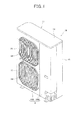
- Fig. 1 is a perspective view showing the outdoor unit 10.
- the outdoor unit 10 has a substantially rectangular parallelepiped box-shaped unit case (housing) 11, and the unit case 11 has a bottom plate 12, a top panel 13, a front panel 14 and an outer plate 15.
- the inside of the unit case 11 is vertically partitioned into a heat exchange chamber R1 and a machine chamber R2 by a partition plate 16 erected from the bottom plate 12 described later.
- the front panel 14 is divided into right and left parts with a partition member 60 set as the boundary therebetween, and constructed by a first front panel 14A and a second front panel (front panel) 14B.
- a worker can perform a maintenance work for parts in the heat exchange chamber R1 from the front surface side of the outdoor unit 10 by detaching the first front panel 14A from the unit case 11.
- the worker can perform a maintenance work for parts in the machine chamber R2 from the front side of the outdoor unit 10 by detaching the second front panel 14B from the unit case 11.
- two air blow-out ports 28 through which air heat-exchanged with refrigerant in the heat exchange chamber R1 is blown out are formed in the first front panel 14A at the heat exchange chamber R1 side so as to be arranged side by side in the up-and-down direction.
- Each of the air blow-out ports 28 is covered by a mesh-like fan guard 29.
- the air blow-out ports 28 are covered by rounded flange type fan cover portions.
- air blowers 22 described later are provided in the opening portions of the fan cover portions.
- Fig. 2 is a perspective view showing the outdoor unit 10 under the state that the top panel 13, the front panel 14 and the outer plate 15 are detached from the outdoor unit 10.
- the inside of the unit case 11 is sectioned into a heat exchange chamber R1 and a machine chamber R2 by the partition member 60 .
- the partition member 60 has a partition plate 16 which is provided to be substantially vertical to the bottom plate 12 and extend in the longitudinal direction, and an electrical component mount unit 40 joined to the upper end portion of the partition plate 16.
- the heat exchange chamber R1 is provided with a heat exchanger 21 at the back side thereof, and air blowers 22 are arranged side by side in the up-and-down direction at the front surface side of the heat exchange chamber R1.
- the heat exchanger 21 is designed to be bent substantially in an L-shape in top view.
- the heat exchanger 21 is disposed to extend from the left side surface (outer surface) of the heat exchange chamber R1 along the back surface.
- the heat exchanger 21 forms the left and back side surfaces of the heat exchange chamber R1 (that is, the unit case 11). That is, the whole exposed surface from the left side surface to the back surface of the heat exchange chamber R1 functions as a ventilation path (suction port).
- the surface of the heat exchanger 21 is covered by a fin guard formed of a resin net or the like to prevent a human body or the like from coming into contact with the heat exchanger 21.
- Each air blower 22 is secured to a pair of right and left support poles 24L and 24R arranged in the heat exchange chamber R1. These support poles 24L and 24R are arranged so that the upper end portions thereof are hooked to the upper edge portion of the heat exchanger 21. Furthermore, the lower end portions of the support poles 24L and 24R are fixed to the bottom plate 12 of the unit case 11 by screws.
- Each air blower 22 has a fan motor 26 fixed to the upper portions of the support poles 24L and 24R through a seat 25 and a propeller fan (axial fan) 27 secured to the shaft of the fan motor 26.
- the propeller fan 27 is disposed in proximity to the front surface side of the heat exchange chamber R1. When the propeller fan 27 is rotated by the fan motor 26, outside air is sucked into the heat exchange chamber R1 from the surroundings of the outdoor unit 10, more specifically, from the back side surface and the left side surface side of the heat exchanger 21.
- the outside air sucked into the heat exchange chamber R1 is heat-exchanged with refrigerant flowing in the heat exchanger 21, and then discharged through the air blow-out ports 28 provided to the front surface of the heat exchange chamber R1 to the outside of the outdoor unit 10. That is, the outdoor unit 10 is constructed as a front air blowing type which blows out heat-exchanged air from the front surface of the outdoor unit 10.
- Refrigerant circuit constructing parts suchas a compressor 31, an accumulator (not shown), a receiver tank 33, anoil separator (not shown), valve elements such as a four-way valve 32, an expansion valve (not shown), etc. which constitute a part of the refrigerant circuit and are connected to one another through pipes are mounted in a lower space of the machine chamber R2 .
- the compressor 31 is driven while the rotational torque thereof is controlled by a PWM (Pulse Width Modulation) inverter.
- the machine chamber R2 is provided with a reactor 80 (see Fig. 3 ) for subjecting the compressor 31 to inverter control which will be described in detail later,
- a service valve for a gas pipe and a service valve for a liquid pipe are fixed proximately to each other at the upper right side of the compressor 31 at the front surface side of the machine chamber R2.
- a gas pipe and a liquid pipe (not shown) of a unit pipe extending from an indoor unit are connected to the service valve for the gas pipe and the service valve for the liquid pipe respectively, thereby constructing a refrigerant circuit through which refrigerant is circulated,
- the electrical component mount unit 40 is disposed in an upper space of the machine chamber R2.
- the electrical component mount unit 40 has various kinds of parts such as a control board for controlling the air conditioner, etc.
- the electrical component mount unit 40 has a first board 41, a second board 42, a heat sink 55 and a support member 50 for supporting electrical components.
- the support member 50 is joined to the upper end portion of the partition plate 16, and supports the heat sink 55 so that the heat sink 55 faces the heat exchange chamber R1. Accordingly, fins 55A of the heat sink 55 protrude to the heat exchange camber R1 side.
- the support member 50 extends in the width direction of the partition plate 16, that is, in the front-and-rear direction of the unit case 11. Furthermore, the support member 50 is provided over an area located from the upper end of the partition plate 16 to the top panel 13 of the unit case 11.
- the partition plate 16 has a partition plate portion 16B disposed between the heat exchange chamber R1 and the machine chamber R2 to insulate the heat exchange chamber R1 and the machine chamber R2 from each other, a front surface portion (end portion) 16C formed by bending the side edge portion of the front surface side of the partition plate portion 16B to the machine chamberR2 side, a back surface portion (endportion) 16D formed by bending the side edge portion of the back surface side of the partition plate portion 16B to the machine chamber R2 side substantially in parallel to the front surface portion 16C, and an upper surface portion (upper end surface) 16A formed by bending the upper edge portion of the partition plate portion 16B to the machine chamber R2 side.
- the partition plate 16 is formed by bending a thin metal plate as described above.
- the partition plate 16 is enhanced in rigidity (strength) because the respective edges thereof are bent.
- the partition plate 16 is provided to erect on the bottom plate 12, and the back surface portion 16D thereof is fixed to the heat exchanger 21 by screws.
- the heat exchanger 21 is provided with a tube plate 35 at the right end portion thereof.
- a rib 35A is formed at the tube plate 35 by bending the inner side edge portion of the unit case 11 substantially in an L-shape.
- the back surface portion 16D of the partition plate 16 is fixed to the rib 35A by screws, whereby the partition plate 16 is fixed to the heat exchanger 12.
- the opening portion 5 for allowing the heat exchange chamber R1 and the machine chamber R2 to be continuous with each other is provided above the partition plate 16.
- the electrical component mount unit 40 is mounted on the upper surface portion 16A of the partition plate 16, and the support member 50 and the partition plate 16 are joined to each other.
- the electrical component mount unit 40 has a board holder 51 for fixing the first board 41 and the heat sink 55 integrally with each other.
- the first board 41 and the heat sink 55 are freely detachably supported on the support member 50 integrally with the board holder 51.
- the support member 50 faces the opening portion 5 for allowing the heat exchange chamber R1 and the machine chamber R2 to be continuous with each other, and has a pair of guide rails 43 provided just above the partition plate 16.
- the guide rails 43 are configured to have a substantially U-shape in section and arranged to face each other.
- One of the guide rails 43 extends to the front surface portion 16C of the partition plate 16, and the other guide rail 43 extends so as to be adjacent to the back surface portion 16D of the partition plate 16.
- the board holder 51 is provided between the guide rails 43. Specifically, the board holder 51 is configured to be guided integrally with the first board 41 and the heat sink 55 by the guide rails 43 under the state that both the side edge portions 51A thereof are fitted in the respective insides of the guide rails 43 and pulled out to the upper side of the partition plate 16.
- the board holder 51 is formed to have a frame-like shape by resin molding.
- the board holder integrally fixes the first board 41 for mounting electrical parts having a large amount of heat generation such as a hybrid IC (HIC) 57, etc. to the heat sink 55 which is thermally connected to electrical parts mounted on the first board 41 and radiates heat generated from these electrical parts.
- HIC hybrid IC
- the first board 41 is fixed to the board holder 51 by screws or the like so that the electrical components having a large amount of heat generation are fitted in the opening of the frame-like board holder 51 to close the opening.
- the electrical components having a large amount of heat generation mounted on the first board 41 are thermally connected to the heat sink 55 through the opening of the board holder 51.
- the heat sink 55 is configured so that plural metal plate members constituting the fins 55A are arranged to be spaced from one another in the up-and-down direction.
- the heat sink 55 is fixed to the board holder 51 so that the plural fins 55A protrude to the heat exchange chamber R1 side through the opening portion 5 for allowing the heat exchange chamber R1 and the machine chamber R2 to be continuous with each other.
- the first board 41 and the heat sink 55 are fixed to the board holder 51 so as to close the opening portion 5 through which the heat exchange chamber R1 and the machine chamber R2 are made to be continuous with each other.
- the electrical component mount unit 40 is provided with the heat sink 55 so that the plural fins 55A of the heat sink 55 protrude to the heat exchange chamber R1 side through the opening portion 5 for allowing the heat exchange chamber R1 and the machine chamber R2 to be continuous with each other.
- the electrical component mount unit 40 can radiate the heat generated from the electrical components mounted on the first board 41 by the heat sink 55, and also cool the heat sink 55 by air flowing in the heat exchange chamber R1. Accordingly, the heat generated from the electrical component mounted on the first board 41 can be efficiently radiated.
- a hood 59 covering most of the whole projection area of the heat sink 55 is provided at the upper side of the heat sink 55.
- the hood 59 may be fixed to the board holder 51.
- the hood 59 is opened upwardly, and designed to be substantially box-shaped such that one side surface thereof at the machine chamber R2 side is cut out in the front-and-rear direction. Furthermore, the hood 59 is designed so that the upper end surfaces 59B of the other three side surfaces 59A thereof come into contact with the lower surface of the top panel 13 of the unit case 11.
- water such as rain water or the like which infiltrates from the back surface side of the heat exchanger 21 into the heat exchange chamber R1 can be prevented from infiltrating from the upper side of the heat sink 55 into the machine chamber R2 side by the hood 59.
- the bottom surface 59C of the hood 59 is cut out along the side surface 59A of the hood 59 at the heat exchange chamber R1 side to form a cut-out portion 59D through which the upper space of the hood 59 and the heat exchange chamber R1 are made continuous with each other.
- Air in the machine chamber R2 is attracted by air flowing in the heat exchange chamber R1, and thus flows through the cut-out portion 59D into the heat exchange chamber R1. Therefore, air which is heated by heat generated from the electrical components of the electrical component mount unit 40 can be circulated without staying in the machine chamber R2.
- the support member 50 has a second board fixing plate 45 for supporting the second board 42 substantially vertically to the first board 41.
- the second board fixing plate 45 has a second board fixing portion 45A provided substantially in parallel to the guide rails 43, and a base portion 45B which is fixed to the lower portion of the second board fixing portion 45A and formed to be substantially L-shaped in section.
- the second board 42 is fixed to the second board fixing portion 45A by a fastening member such as a screw 47 or the like.
- the second board 42 may be pinched to the second board fixing portion 45A by a clamp member such as a clip or the like.
- the base portion 45B is provided to the lower end of the second board fixing portion 45A so as to protrude to the front surface side of the machine chamber R2 .
- a terminal block fixing portion 45C having plural terminal blocks 46A and 46B to which a power source terminal and connectors are connected is provided to the base portion 45B so as to hang to the lower side of the electrical component mount unit 40.
- a communication line for communicating with the indoor unit, etc. is connected to the terminal block 46A, and a power source line for supplying power to the outdoor unit 10 is connected to the terminal block 46B. Furthermore, clips 46C and 46D for fixing the communication line and the power source line are secured to the terminal block fixing portion 45C.
- Fixing portions 45D are formed at the left edges of the second board fixing portion 45A and the base portion 45B. As not shown, the fixing portions 45D are designed to extend to the confronting face between the outer plate 15 and the second front panel 14B, and the edge of the outer plate 15 is bent to the inside of the unit case 11 and fixed to the side edge portion (the fixing portions 45D) by screws.
- the second board fixing portion 45A, the base portion 45B, the terminal block fixing portion 45C and the fixing portions 45D may be formed integrally with one another by subjecting one metal plate to sheet metal processing such as bending or the like.
- the board holder 51 has a hook member 58 provided above the first board 41.
- the hook member 58 is formed of metal such as aluminum or the like and has a hook pawl 58A which is provided at the tip of the hook member 58 and formed by bending the tip of the hook member 58 downwardly. Furthermore, a hook groove 58B is formed on the upper end surface of the second board fixing plate 45A. When the board holder 51 is fixed to the support member 50, the hook pawl 58A is hooked to the hook groove 58B.
- the board holder 51 has two screw holes 51E which are provided to the upper portion of the board holder 51 so as to be located in the neighborhood of the guide rails 43.
- the board holder 51 is fixed to the support member 50 through the screw holes 51E by screws inserted from the machine chamber R2 side. That is, the board holder 51 is fixed to the support member 50 at three points of the hook pawl 58A and the screw holes 51E.
- the hook pawl 58A and the screw holes 51 used to fix the board holder 51 to the support member 50 are provided to the upper portion of the board holder 51, and thus the board holder 51 can be easily detached from the upper opening of the outdoor unit 10 from which the top panel 13 is detached.
- the support member 50 has a plate-like member 54 which extends to the back surface portion 16D of the partition plate 16 so as to cover the whole support member 50 in the up-and-down direction.
- the plate member 54 is fixed to the side surface at the heat exchange chamber R1 side of the guide rail 43 located at the rear side of the unit case 11 by screws or the like so that the plate member 54 overhangs the back surface side of the support member 50, and bent substantially in L-shape to the machine chamber R2 side along the back surface portion 16D. Accordingly, a recess portion 54A in which a rib 35A formed on the tube plate 35 of the heat exchanger 21 is fitted is formed between the plate-like member 54 and the rear guide rail 43 in the support member 50.
- the back surface portion 16D of the partition plate 16 is fixed through screws to the rib 35A formed on the tube plate 35 of the heat exchanger 21 fixedly erected on the bottom plate 12, thereby fixing the partition plate 16 to the tube plate 35, and the support member 50 with which the electrical component mount unit 40 is integrated is mounted on the upper surface portion 16A of the partition plate portion 16B while the rib 35A is fitted, in the recess portion 54A. Subsequently, as shown in Fig. 5 , the front surface 54C of the back surface side edge portion 54B of the plate-like member 54 is brought into contact with the back surface 35B of the rib 35A, and the back surface side edge portion 54B is fixed to the rib 35A at two places in the up-and-down direction by screws. In the last step of the assembling process of the outdoor unit 10, the electrical component mount unit 40 is mounted in the unit case 11 by fixing the outer plate 15 to the unit case 11 and then fixing the fixing portions 45D of the support member 50 to the outer plate 15 by screws or the like.
- the support member 50 has a support plate 48 having a substantially L-shaped section for joining the second board fixing portion 45A to the guide rails 43.
- a space R3 is formed between the back surface side of the second board 42 and the first board 41 by the support plate 48, and an electrolytic capacitor 56 accommodated in the space R3 is mounted on the first board 41.
- the rigidity of the support member 50 for supporting the first board 41 and the second board 42 substantially in L-shape can be enhanced by the support plate 48, so that the electrical component mount unit 40 can be reduced in weight.
- the electrolytic capacitor 56 is surrounded by the support plate 48 and accommodated in the space R3. Therefore, it can be prevented that another part hits against the electrolytic capacitor 56 and thus the electrolytic capacitor 56 is broken during the assembling work.
- Fig. 6 is a perspective view showing the partition plate 16 and the electrical component mount unit 40 when they are viewed from the back surface side of the outdoor unit 10 under the state that the heat exchanger 21 and the outer plate 15 are detached,
- the heat exchanger 21 is secured to the unit case 11 before the partition plate 16 is secured to the unit case 11, and the back surface portion 16D of the partition plate 16 and the plate-like member 54 are fixed to the tube plate 35 of the heat exchanger 21 by screws or the like.
- the hood 59 is provided to the upper portion of the heat sink 55 which is fitted in the opening portion 5 at both the endportions thereof in the front-and-rear direction. Airpassed through the heat exchanger 21 and sucked into the heat exchange chamber R1 by the air blowers 22 flows between the plural fins 55A of the heat sink 55 as indicated by an arrow of Fig. 6 . There is a case where water such as rain water or the like infiltrates into the heat exchanger 21 along air flow. The water infiltrating into the heat exchange chamber R1 scatters due to rotation of the propeller fan 27s of the air blowers 22, and impinges against a surface of the support member 50 which is exposed to the heat exchange chamber R1 side and the heat sink 55.
- the hood 59 is provided to the upper portion of the heat sink 55, and water can be prevented from infiltrating from the upper side of the heat sink 55 to the machine chamber R2 side,
- a first support plate 44 is provided to the support member 50 at the lower side of the heat sink 55 so as to connect the guide rails 43 and close the lower portion of the opening portion 5 though which the heat exchange chamber R1 and the machine chamber R2 are continuous with each other. Furthermore, a water infiltration preventing plate 65 which is integrally fixed to the heat sink 55 is fixed to the board holder 51. The water infiltration preventing plate 65 is provided so as to cover the upper end portion of the support plate 44, thereby preventing water infiltration from the upper side of the first support plate 44 to the contact face between the first support plate 44 and the board holder 51.
- the cooling efficiency of the heat sink 55 is enhanced without providing any cover at the front and rear sides of the heat sink 55, that is, at air entrance and exist sides of the fins S5A. That is, air which is sucked into the heat exchange chamber R1 and passed through the heat exchanger 21 by the air blowers 22 flows through each gap between the fins 55A of the heat sink 55. Therefore, water such as rain water or the like may infiltrate from the air entrance and exist ports of the fins 55A into the fitting face S1 between the heat sink 55 and the opening portion 5 at both the front and rear sides of the heat sink 55.
- Fig. 7A is a cross-sectional perspective view of the electrical component mount unit 40 and the partition plate 16 which is taken along a line a-a of Fig. 4 when they are viewed from an arrow X direction in Fig. 4
- Fig. 7B is an enlarged cross-section showing the arrangement relation between a seat portion and a water infiltration preventing portion in a dotted circle A of Fig. 7A
- a water infiltration preventing portion (water-proof preventing portion) 16E is provided to the upper surface portion 16A of the partition plate portion 16B on which the support member 50 is mounted.
- the water infiltration preventing portion (water-proof portion) 16E is formed by bending the upper end portion of the partition plate portion 16B to the machine chamber R2 side to form an upper surface portion 16A and further bending the upper surface portion 16A substantially vertically and upwardly.
- This water infiltration preventing portion 16E is provided so as to surround the end portion at the machine chamber R2 side of a seat portion 52 which is formed by bending the lower end of the first support plate 44 to the machine chamber R2 side substantially in L-shape and on which the lower end of the board holder 51 is mounted.
- the water collected by the seat portion 52 is passed through the gap between the upper surface portion 16A of the partition plate portion 16B and the seat portion 52, and discharged to the heat exchange chamber R1 side. Therefore, the heat sink 55 can be efficiently cooled without blocking the air passage between the fins 55A of the heat sink 55, and water infiltration to the machine chamber R2 side can be prevented.
- a reactor for an inverter of a compressor is secured to an electrical component mount unit so as to face an opening for service at the front surface side of the unit case so that maintenance for the reactor can be easily performed. Since the reactor has a large amount of heat generation, it is necessary that an opening for ventilation is formed in the unit case and outside air is taken from this ventilation opening into the machine chamber to cool the reactor with the air.
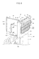
- a reactor 80 of a compressor 31 is secured to the upper portion at the machine chamber R2 side of the partition plate portion 16B as shown in Fig. 8 .
- the electrical component mount unit 40 is provided above the reactor 80.
- the electrical component mount unit 40 is joined to the upper portion of the partition plate 16, and functions as a partition body for partitioning the inside of the unit case 11 into the heat exchange chamber R1 and the machine chamber R2 together with the partition plate 16.
- the water infiltration preventing portion 16E is provided above the reactor 80. Accordingly, water infiltrating to the machine chamber R2 can be prevented from dripping to the reactor 80 along the partition plate 16 by the water infiltration preventing portion 16E. Therefore, it is unnecessary to cover the reactor 80 by a water-proof cover or the like, and the waterproof of the reactor 80 can be performed with a simple construction.
- the reactor has a metal case 81 having a substantially rectangular shape and a winding wire mounted in the metal case 81.
- the case 81 is fixed to a mount plate (mount member) 83 for mounting the reactor 80 to the partition plate 16 .
- the reactor 80 is freely detachably mounted on the partition plate portion 16B through the mount plate 83.
- the mount plate 83 is formed of a metal thin plate having a high thermal conductivity.
- the mount plate 83 is designed so as to extend in the width direction of the contact face of the case 81 with the partition plate portion 16B and have a dimension larger than the dimension of the case 81 in the up-and-down direction.
- the reactor 80 is supported on the partition plate portion 16B so that one surface of the mount plate 83 is brought into close contact with the case 81 and the other surface of the mount plate 3 is brought into close contact with the partition plate portion 16B.
- the mount plate 83 is fixed to the upper portion of the partition plate 16B by screws 84.
- the mount plate 83 may be formed integrally with the case 81.
- the reactor 80 is provided with reactor terminals 90A and 90B.
- the reactor 80 is connected through the reactor terminals 90A and 90B to electrical parts having a large amount of heat generation such as the hybrid IC 57, etc. mounted on the first board 41.
- the hybrid IC 57 enhances the power factor and controls harmonics by using the reactor 80 to perform the inverter control on the compressor 31.
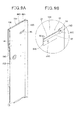
- the partition plate portion 16B is provided with a support member 85 for supporting the mount plate 83 integrally with the reactor 80.
- the support member 85 is formed to have a predetermined shape by subjecting one metal plate to sheet-metal processing such as bending processing or the like.
- the support member 85 has a first fixing portion 86A for fixing the support member 85 to the partition plate portion 16B.
- the support member 85 further has a support portion 87 which is formed by bending the metal plate substantially in L-shape in section so as to protrude from the first fixing portion 86A to the machine chamber R2 side, thereby forming a gap (opening) S2 between the partition plate portion 16B and the support member 85.
- the support member 85 is further configured so that a rearward extending portion of the support portion 87 is bent to the partition plate portion 16B side substantially in L-shape in section to form a rear end portion 89 which blocks the rear opening (gap) between the support portion 87 and the partition plate 16B.
- the support member 85 is provided with a second fixing portion 86B for fixing the support member 85 to the partition plate portion 16B at the rear end portion 89 side. Screw holes 86C are formed in the first fixing portion 86A and the second fixing portion 86B.
- the support member 85 is fixed to the partition plat portion 16B by screws inserted into the screw holes 86C.
- the upper edge of the support portion 87 is outwardly bent by an angle ⁇ to form an upper edge portion 88.
- the gap S2 between the partition plate portion 16B and the support portion 87 is opened at the front side of the support portion 87.
- the reactor 80 is freely detachably secured to the partition plate portion 16B by inserting and sliding the lower edge portion of the mount plate 83 from this opening into the gap S2. Since the upper edge portion 88 is provided to the upper edge of the support portion 87, the lower edge of the mount plate 83 is guided along the upper edge portion 88, and the mount plate 83 can be easily inserted into the gap S2.
- the reactor 80 can be easily supported at a desired position by sliding the mount plate 83 rearwards until the rear edge of the mount plate 83 abuts against the rear end portion 89 of the support member 85 while the mount plate 83 is guided by the support portion 87.
- Plural screw holes 86D are formed in the partition plate portion 16B above the support member 85.
- the upper portion of the mount plate 83 is fixed to the partition plate portion 16B by screws inserted in the screw holes 86D under the state that the lower edge portion of the mount plate 83 is supported by the support portion 87, whereby the reactor 80 is fixed to the partition plate portion 16B.
- the mount plate 83 for fixing the reactor 80 to the partition plate portion 16B is supported to be lifted from the lower side by the support member 85. Accordingly, the mount plate 83 can be fixed to the partition plate portion 16B by screws while the weight of the reactor 80 is supported by the support member 85. Accordingly, the workability of fixing the reactor 80 to the partition plate 16 can be enhanced.
- the outdoor unit 10 for the air conditioner is provided with the vertically extending partition body 60 through which the inside of the unit case (housing) 11 is partitioned into the heat exchange chamber R1 and the machine chamber R2.
- the heat exchanger 21 and the air blowers 22 are mounted in the heat exchange chamber R1, and the compressor 31 and the electrical component mount unit 40 are mounted in the machine chamber R2.
- the partition body 60 has the partition plate 16 provided substantially vertically to the bottom plate 12 of the unit case 11, and the electrical component mount unit 40 connected to the upper end portion of the partition plate 16.
- the electrical component mount unit 40 is constructed by securing the heat sink 55 to the board holder 51 constituting the upper portion of the partition body 60.
- the board holder 51 is allowed to be guided by a pair of guide rails 43 while the heat sink 55 faces the heat exchange chamber R1 side, and upwardly pulled out of the upper portion of the partition body 60. Furthermore, the water infiltration preventing portion 16E is provided to dam water infiltrating through the fit face between the guide rails 43 and the board holder into the machine chamber R2 side and discharge the dammed water to the heat exchange chamber R1 side. Accordingly, the water infiltration preventing portion 16E can dam the water infiltrating from the heat exchange chamber R1 side through the fit face between the guide rails 43 and the board holder 51 to the machine chamber R2 side and discharge the water to the heat exchange chamber R1 side. Therefore, the water infiltration to the machine chamber R2 can be prevented with a simple construction.
- the pair of guide rails 43 are joined to the upper surface portion (the upper end portion) 16A of the partition plate portion 16B, and the water infiltration preventing portion 16E is formed by bending the upper surface portion 16A of the partition plate portion 16B to the machine chamber R2 side and also bending the bent upper surface portion 16A upwardly. Accordingly, the water infiltration preventing portion 16E can be easily formed without increasing the number of parts and without forming any gap for allowing water infiltration to the machine chamber R2 side at the joint portion between the upper surface portion 16A and the water infiltration preventing portion 16E, so that the water infiltration to the machine chamber R2 can be prevented with a simple construction.
- the pair of guide rails 43 are disposed to face the opening portion 5 through which the machine chamber R2 and the heat exchange chamber R1 are continuous with each other, configured substantially in L-shape in section and arranged so as to face each other.
- the side edge portions of the board holder 51 are inserted into the insides of the guide rails 43, and the opening portion 5 is blocked by the board 41 which is fixed to the board holder 51 integrally with the heat sink 55. Accordingly, the maintenance of the board 41 can be easily performed by easily and integrally detaching the board 41 and the heat sink 55 from the support member 50, and the maintenance performance of the board 41 can be enhanced.
- the electrical parts mounted on the board 41 are thermally connected to the heat sink 55, the heat sink 55 is cooled by air flowing in the heat exchange chamber R1, so that heat generated from the electrical parts can be efficiently radiated through the heat sink 55.
- the electrical component mount unit 40 has the support member 50 joined to the upper end portion of the partition plate 16, and the guide rails 43 are provided to the support member 50. Accordingly, the support member 50 is joined to the partition plate 16, and the board holder 51 is fitted in the guide rails 43 provided to the support member 50, whereby the opening portion 5 for making the machine chamber R2 and the heat exchange chamber R1 continuous with each other can be blocked and the inside of the unit case 11 can be partitioned into the heat exchange chamber R1 and the machine chamber R2 .
- the heat sink 55 can be set to face the heat exchange chamber R1 side through the opening portion 5, and also the heat sink 55 and the board 41 can be integrally upwardly pulled out from the upper portion of the partition body 60. Accordingly, the workability of the assembly of the electrical component mount unit 40 to the unit case 11 can be enhanced, and the maintenance performance of the board 41 can be enhanced. Furthermore, the water infiltration from the heat exchange chamber R1 side to the machine chamber R2 side can be prevented by the water infiltration preventing portion 16E. Therefore, it is unnecessary to provide a packing for preventing water infiltration or the like to the fitting face between each guide rail 43 and the board holder 51, and the board holder 51 can be easily upwardly pulled out from the guide rails 43.
- the support member 50 supports the second board 42 substantially in T-shape with respect to the first board 41. Accordingly, maintenance of the second board 42 can be performed from the opening at the front surface side of the machine chamber R2 from which the second front panel 14B is detached without detaching the electrical component mount unit 40 from the unit case 11, so that the maintenance performance of the electrical component mount unit 40 can be enhanced. Furthermore, the water infiltration from the heat exchange chamber R1 side to the machine chamber R2 side can be prevented by the water infiltration preventing portion 16E, and therefore, it is unnecessary to cover the electrical component mount unit 40 by a cover or the like. Therefore, the number of parts of the electrical component mount unit 40 can be reduced, and the maintenance performance can be enhanced.
- the board holder 51 is integrally provided with the hood 59 which is provided above the heat sink 55 and blocks the opening portion 5 for allowing the machine chamber R2 and the heat exchange chamber R1 to be continuous with each other, and the first support plate 44 and the water infiltration preventing plate 65 which are provided below the heat sink 55 and block the opening portion 5. Accordingly, water such as rain water or the like can be prevented from infiltrating from the heat exchange chamber R1 side to the machine chamber R2 side through the gap between the heat sink 55 and the top panel 13 or the gap between the lower portion of the board holder 51 below the heat sink 55 and the support member 50. Therefore, the water infiltration from the machine chamber R2 can be prevented with a simple construction.
- the outdoor unit 10 for the air conditioner is provided with the vertically extending partition body 60 through which the inside of the unit case (housing) 11 is partitioned into the heat exchange chamber R1 and the machine chamber R2 and the second front panel 14B which is provided at the front surface side of the machine chamber R2 so as to be freely detachable.
- the partition body 60 comprises the partition plate 16 provided substantially vertically to the bottom plate 12 of the unit case 11, and the electrical component mount unit 40 joined to the upper end portion of the partition plate 16.
- the electrical component mount unit 40 has the board 41 and the reactor 80 connected to the board 41 is secured to the surface at the machine chamber R2 side of the partition plate 16 so as to be freely attachable/detachable through the front-side opening of the machine chamber R2 from which the second front panel 14B is detached. Accordingly, the reactor 80 can be attached/detached through the front-side opening of the machine chamber R2, and the maintenance performance of the reactor 80 can be enhanced with a simple construction. Furthermore, the reactor 80 is secured to the partition plate 16. Therefore, the heat of the reactor 80 can be radiated by using the partition plate 16 without providing any ventilation opening to the second front panel 14B. Accordingly, the heat of the reactor 80 can be radiated without providing any ventilation opening portion through which water such as rain water or the like may infiltrate to the machine chamber R2 side, and the water infiltration to the machine chamber R2 can be prevented with a simple construction.
- the reactor 80 has the substantially rectangular case 81 containing the winding wire 82, and the plate-like mount plate 83 which is disposed between the case 81 and the partition plate 16 to transfer heat generated from the reactor 80 to the partition plate 16 and mount the reactor 80 onto the partition plate 16 is provided integrally with the case 81. Accordingly, the attachment/detachment of the reactor 80 to/from the partition plate 16 can be easily performed. Furthermore, the heat generated from the reactor 80 can be efficiently transferred to the partition plate 16 through the mount plate 83.
- the partition plate 16 is air-cooled by air flowing in the heat exchange chamber R1, so that the heat transferred from the reactor 80 to the partition plate 16 can be efficiently radiated by using the partition plate 16.
- the plate-like mount plate 83 forms a heat radiation face 81A for the case 81
- the reactor 80 and the partition plate 16 are joined to each other while the heat radiation face 81 is brought into contact with the partition plate 16, and the partition plate 16 has the support member 85 to which the mount plate 83 is freely detachably fitted.
- the partition plate 16 and the plate-like mount plate 83 can be detachably secured to each other while the heat radiation face 81A for the case 81 is brought into close contact with the partition plate 16.
- the heat generated from the reactor 80 can be efficiently transferred to the partition plate 16 through the mount plate 83, and further radiated to the air flowing in the heat exchange chamber R1.
- the reactor 80 can be fixed to the partition plate 16 while supported on the support member 85, so that the reactor 80 can be easily attached/detached and the maintenance performance of the reactor 80 can be enhanced.
- the support member 85 forms the gap S2 between the support member 85 and the partition plate 16, and the lower edge of the mount plate 83 is fitted in the gap S2, whereby the mount plate 83 is supported from the lower side. Accordingly, the support member 85 makes it easy to fix the reactor 80 which is difficult to be fixed by screws or the like while the reactor 80 is supported by one hand because the reactor 80 is relatively weighty. Therefore, the maintenance performance of the reactor 80 can be enhanced.
- the gap S2 is opened at the front side thereof, and the lower edge portion 83C of the mount plate 83 is slid from the opening concerned into the gap S2, whereby the reactor 80 is freely detachably supported on the partition plate 16. Accordingly, the reactor 80 can be fixed to the partition plate 16 by sliding the mount plate 83 into the gap between the support member 85 and the partition plate 16 from the front-side opening of the machine chamber R2 from which the second front panel 14B is detached. Accordingly, the reactor 80 can be easily attached and detached, and thus the maintenance performance of the reactor 80 can be enhanced.
- the water infiltration preventing portion 16E for preventing water infiltration from the heat exchange chamber R1 to the machine chamber R2 is provided to the partition plate 16, whereby water such as rain water or the like can be prevented from infiltrating from the heat exchange chamber R1 side to the machine chamber R2 side of the partition plate 16. Accordingly, the reactor 80 can be prevented from being wetted with water such as rain water or the like without covering the reactor 80 with any water-proof cover or the like. Therefore, the number of parts can be reduced, and the service performance of the reactor 80 can be enhanced.
- the partition plate 16 is provided with the water infiltration preventing portion 16E for preventing water infiltration from the heat exchange chamber R1 to the machine chamber R2, thereby preventing infiltration of water such as rain water or the like from the heat exchange chamber R1 side to the machine chamber R2 side of the partition plate 16. Accordingly, the reactor 80 can be prevented from being wetted with water such as rain water or the like without covering the reactor 80 with any water-proof cover or the like. Therefore, the number of parts can be reduced, and the service performance of the reactor 80 can be enhanced.
Landscapes
- Engineering & Computer Science (AREA)
- Chemical & Material Sciences (AREA)
- Combustion & Propulsion (AREA)
- Mechanical Engineering (AREA)
- General Engineering & Computer Science (AREA)
- Other Air-Conditioning Systems (AREA)
Abstract
Description
- The present invention relates to an outdoor unit for an air conditioner.
- There is generally known an outdoor unit for an air conditioner in which the inside of a housing is partitioned into a heat exchange chamber and a machine chamber through a partition plate erected from a bottom plate and a heat exchanger and an air blower are mounted in the heat exchange chamber while a compressor and an electric component mount unit are mounted in the machine chamber. In this type outdoor unit, a heat sink for radiating heat generated from electrical components mounted in the electrical component mount unit is joined to the electrical component mount unit. An opening portion through which the heat exchange chamber and the machine chamber are continuous with each other is provided inside the housing, for example, at the upper side of the partition plate. The heat sink is fixed so as to face the heat exchange chamber through the opening portion, whereby the heat sink is cooled by air flowing in the heat exchange chamber. Furthermore, in this type outdoor unit, the heat sink is covered by a water-proof cover or a water infiltration preventing plate is secured to the opening portion to prevent water such as rain water or the like from infiltrating from the heat exchange chamber side into the machine chamber side through the opening portion through which the heat exchange chamber and the machine chamber are made to be continuous with each other (see
JP-A-2009-186091 - However, when the heat sink is covered by the water-proof cover, the stream of air blown to the heat sink is hindered by the water-proof cover, and thus the cooling efficiency of the heat sink is lowered. Furthermore, when the water-immersion preventing plate is secured to the opening portion through which the heat exchange chamber and the machine chamber are made continuous with each other, in order to prevent infiltration of water from the fitting face between the heat sink and the opening portion into the machine chamber, it is required to secure a packing or the like to the fitting face, so that workability of assembling the electrical component mount unit to the outdoor unit is low.
- The present invention has been implemented in view of the foregoing situation, and has an object to provide an outdoor unit for an air conditioner that can prevent water infiltration (immersion) into a machine chamber with a simple structure.
- In order to attain the above object, according to an aspect of the present invention, an outdoor unit (10) for an air conditioner that has a vertically extending partition body (60) through which the inside of a housing (11) is partitioned into a heat exchange chamber (R1) and a machine chamber (R2) and is configured so that a heat exchanger (21) and an air blower (22) are mounted in the heat exchange chamber (R1) and a compressor (31) and an electrical component mount unit (40) are mounted in the machine chamber (R2), is characterized in that the partition body (60) comprises a partition plate (16) provided substantially vertically to a bottom plate (12) of the housing (11), and the electrical component mount unit (40) connected to an upper end portion of the partition plate; the electrical component mount unit (40)has a board holder (51) constituting an upper portion of the partition body and a heat sink (55) secured to the board holder; the board holder (51) is configured to be guided by a pair of guide rails (43) while the heat sink faces the heat exchange chamber side, and upwardly pulled out from the upper portion of the partition body; andawater-proof portion (16E) is provided to dam water infiltrating through the fitting face between each of the guide rails and the board holder into the machine chamber side and discharge the dammed water to the heat exchange chamber R1 side.
- In the above outdoor unit, the pair of guide rails are joined to an upper end portion (16A) of the partition plate, and the water-proof portion is formed by bending the upper end portion of the partition plate to the machine chamber side and further bending the bent upper end portion upwardly.
- In the above outdoor unit, the pair of guide rails are rails that are disposed so as to face an opening portion (5) through which the machine chamber and the heat exchange chamber are continuous with each other, configured substantially in L-shape in section and arranged so as to face each other, and the side edge portions of the board holder are inserted into the insides of the
guide rails 43 so that the opening portion (5) is blocked by a first board (41) which is secured to the board holder (51) integrally with the heat sink (55). - In the above outdoor unit, the electrical component mount unit (40) has a support member (50) joined to the upper end portion of the partition plate, and the guide rails are provided to the support member.
- In the above outdoor unit, the support member supports a second board (42) substantially in T-shape with respect to the first board (41).
- In the above outdoor unit, the board holder is integrally provided with a hood (59) that is disposed above the heat sink and blocks the opening portion, and a water infiltration preventing plate (65) which is disposed below the heat sink and blocks the opening portion.
- According to another aspect of the present invention, an outdoor unit (10) for an air conditioner that is provided with a vertically extending partition body (60) through which the inside of a housing (11) is partitioned into a heat exchange chamber (R1) and a machine chamber (R2), and a front panel (14B) freely detachably mounted at the front side of the machine chamber, and configured so that a heat exchanger (21) and an air blower (22) are mounted in the heat exchange chamber (R1) and a compressor (31) and an electrical component mount unit (40) are mounted in the machine chamber (R2), is characterized in that the partition body (60) comprises a partition plate (16) provided substantially vertically to a bottom plate (12) of the housing, and an electrical component mount unit (40) joined to an upper end portionof thepartitionplate, wherein the electrical component mount unit has a board (41), and a
reactor 80 connected to the board (41) is secured to a surface at the machine chamber side of the partition plate so as to be freely attachable and detachable through a front-side opening of the machine chamber from which the front panel is detached. - In the above outdoor unit, according to claim 7, wherein the reactor has a substantially rectangular case (81) having a winding wire (82) mounted therein, and a.plate-like mount plate (83) which is disposed between the case (81) and the partition plate (16) to transfer heat generated from the reactor to the partition plate and through which the reactor is mounted onto the partition plate is provided integrally with the case.
- In the above outdoor unit, the plate-like mount plate (83) forms a heat radiation face (81A) for the case (81) and joins the reactor and the partition plate to each other while the heat radiation face is brought into contact with the partition plate, and the partition plate has a support member (85) to which the mount plate is freely detachably fitted.
- In the above outdoor unit, a gap (S2) is formed between the support member (85) and the partition plate (16), and a lower edge portion (83C) of the mount plate (83) is fitted in the gap (S2), whereby the mount plate is supported from the lower side thereof.
- In the above outdoor unit, the gap (S2) is opened at the front side thereof, and the lower edge portion of the mount plate is slid from the opening into the gap, whereby the reactor is freely detachably supported on the partition plate.
- In the outdoor unit, the partition plate is provided with a water-proof portion (16E) for preventing water infiltration from the heat exchange chamber to the machine chamber.
- According to the present invention, the outdoor unit for the air conditioner is provided with the vertically extending partition body through which the inside of the housing is partitioned into the heat exchange chamber and the machine chamber. The heat exchanger and the air blowers are mounted in the heat exchange chamber, and the compressor and the electrical component mount unit are mounted in the machine chamber. The partition body has the partition plate provided substantially vertically to the bottom plate of the housing, and the electrical component mount unit connected to the upper end portion of the partition plate. The electrical component mount unit is constructed by securing the heat sink to the board holder constituting the upper portion of the partition body. The board holder is allowed to be guided by a pair of guide rails while the heat sink faces the heat exchange chamber side, and upwardly pulled out of the upper portion of the partition body. Furthermore, the water-proof portion is provided to dam water infiltrating through the fit face between the guide rails and the board holder into the machine chamber side and discharge the dammed water to the heat exchange chamber side. Accordingly, the water-proof portion can dam the water infiltrating from the heat exchange chamber side through the fit face between the guide rails and the board holder to the machine chamber side. Therefore, the water infiltration to the machine chamber can be prevented with a simple construction.
-
-
Fig. 1 is a perspective view showing the outlook of an outdoor unit according to an embodiment to which the present invention is applied; -
Fig. 2 is a perspective view showing the internal construction of the outdoor unit; -
Fig. 3 is a perspective view showing the internal construction of the outdoor unit under the state that an electrical component mount unit is detached; -
Fig. 4 is a perspective view showing the electrical component mount unit; -
Fig. 5 is a plan view showing a temporary support structure for the electrical component mount unit; -
Fig. 6 is a perspective view showing the electrical component mount unit and a partition plate when they are viewed from the back side thereof; -
Fig. 7A is a cross-sectional perspective view of the electrical component mount unit and the partition plate which is taken along a line a-a ofFig. 4 when viewed from an arrow X direction inFig. 4 , andFig. 7B is an enlarged cross-section showing the arrangement relation between a seat portion and a water infiltration preventing portion in a dotted circle A ofFig. 7A ; -
Fig. 8 is a perspective view showing a reactor secured to the partition plate; and -
Fig. 9A is a perspective view showing the partition plate having a support member, andFig. 9B is an enlarged view of the support member. - An embodiment according to the present invention will be described hereunder with reference to the drawings.
- An air conditioner according to this embodiment is constructed by an
outdoor unit 10 and an indoor unit (not shown). In the air conditioner, as not shown, refrigerant is made to flow through a refrigerant circuit in which respective parts are connected to one another through refrigerant pipes so that cooling operation and heating operation are performed. Theoutdoor unit 10 is disposed outdoors, and performs heat exchange between the refrigerant and outdoor air, whereby the refrigerant is condensed and heat is radiated to the outside air under cooling operation while the refrigerant is evaporated and heat is taken from the outdoor air under heating operation. The up-and-down and right-and-left directions in the following description represent directions defined when theoutdoor unit 10 is viewed from the front side thereof under the state that theoutdoor unit 10 is installed. -
Fig. 1 is a perspective view showing theoutdoor unit 10. - The
outdoor unit 10 has a substantially rectangular parallelepiped box-shaped unit case (housing) 11, and theunit case 11 has abottom plate 12, atop panel 13, afront panel 14 and anouter plate 15. The inside of theunit case 11 is vertically partitioned into a heat exchange chamber R1 and a machine chamber R2 by apartition plate 16 erected from thebottom plate 12 described later. Thefront panel 14 is divided into right and left parts with apartition member 60 set as the boundary therebetween, and constructed by afirst front panel 14A and a second front panel (front panel) 14B. A worker can perform a maintenance work for parts in the heat exchange chamber R1 from the front surface side of theoutdoor unit 10 by detaching thefirst front panel 14A from theunit case 11. Furthermore, the worker can perform a maintenance work for parts in the machine chamber R2 from the front side of theoutdoor unit 10 by detaching thesecond front panel 14B from theunit case 11. - Furthermore, two air blow-out
ports 28 through which air heat-exchanged with refrigerant in the heat exchange chamber R1 is blown out are formed in thefirst front panel 14A at the heat exchange chamber R1 side so as to be arranged side by side in the up-and-down direction. Each of the air blow-outports 28 is covered by a mesh-like fan guard 29. As not shown, the air blow-outports 28 are covered by rounded flange type fan cover portions. Furthermore,air blowers 22 described later are provided in the opening portions of the fan cover portions. -
Fig. 2 is a perspective view showing theoutdoor unit 10 under the state that thetop panel 13, thefront panel 14 and theouter plate 15 are detached from theoutdoor unit 10. - The inside of the
unit case 11 is sectioned into a heat exchange chamber R1 and a machine chamber R2 by thepartition member 60 . Thepartition member 60 has apartition plate 16 which is provided to be substantially vertical to thebottom plate 12 and extend in the longitudinal direction, and an electricalcomponent mount unit 40 joined to the upper end portion of thepartition plate 16. - The heat exchange chamber R1 is provided with a
heat exchanger 21 at the back side thereof, andair blowers 22 are arranged side by side in the up-and-down direction at the front surface side of the heat exchange chamber R1. Theheat exchanger 21 is designed to be bent substantially in an L-shape in top view. Theheat exchanger 21 is disposed to extend from the left side surface (outer surface) of the heat exchange chamber R1 along the back surface. As described above, theheat exchanger 21 forms the left and back side surfaces of the heat exchange chamber R1 (that is, the unit case 11). That is, the whole exposed surface from the left side surface to the back surface of the heat exchange chamber R1 functions as a ventilation path (suction port). As not shown, the surface of theheat exchanger 21 is covered by a fin guard formed of a resin net or the like to prevent a human body or the like from coming into contact with theheat exchanger 21. - Each
air blower 22 is secured to a pair of right and leftsupport poles support poles heat exchanger 21. Furthermore, the lower end portions of thesupport poles bottom plate 12 of theunit case 11 by screws. - Each
air blower 22 has afan motor 26 fixed to the upper portions of thesupport poles seat 25 and a propeller fan (axial fan) 27 secured to the shaft of thefan motor 26. Thepropeller fan 27 is disposed in proximity to the front surface side of the heat exchange chamber R1. When thepropeller fan 27 is rotated by thefan motor 26, outside air is sucked into the heat exchange chamber R1 from the surroundings of theoutdoor unit 10, more specifically, from the back side surface and the left side surface side of theheat exchanger 21. The outside air sucked into the heat exchange chamber R1 is heat-exchanged with refrigerant flowing in theheat exchanger 21, and then discharged through the air blow-outports 28 provided to the front surface of the heat exchange chamber R1 to the outside of theoutdoor unit 10. That is, theoutdoor unit 10 is constructed as a front air blowing type which blows out heat-exchanged air from the front surface of theoutdoor unit 10. - Refrigerant circuit constructing parts suchas a
compressor 31, an accumulator (not shown), areceiver tank 33, anoil separator (not shown), valve elements such as a four-way valve 32, an expansion valve (not shown), etc. which constitute a part of the refrigerant circuit and are connected to one another through pipes are mounted in a lower space of the machine chamber R2 . Thecompressor 31 is driven while the rotational torque thereof is controlled by a PWM (Pulse Width Modulation) inverter. The machine chamber R2 is provided with a reactor 80 (seeFig. 3 ) for subjecting thecompressor 31 to inverter control which will be described in detail later, - A service valve for a gas pipe and a service valve for a liquid pipe are fixed proximately to each other at the upper right side of the
compressor 31 at the front surface side of the machine chamber R2. A gas pipe and a liquid pipe (not shown) of a unit pipe extending from an indoor unit are connected to the service valve for the gas pipe and the service valve for the liquid pipe respectively, thereby constructing a refrigerant circuit through which refrigerant is circulated, - The electrical
component mount unit 40 is disposed in an upper space of the machine chamber R2. The electricalcomponent mount unit 40 has various kinds of parts such as a control board for controlling the air conditioner, etc. The electricalcomponent mount unit 40 has afirst board 41, asecond board 42, aheat sink 55 and asupport member 50 for supporting electrical components. Thesupport member 50 is joined to the upper end portion of thepartition plate 16, and supports theheat sink 55 so that theheat sink 55 faces the heat exchange chamber R1. Accordingly,fins 55A of theheat sink 55 protrude to the heat exchange camber R1 side. Thesupport member 50 extends in the width direction of thepartition plate 16, that is, in the front-and-rear direction of theunit case 11. Furthermore, thesupport member 50 is provided over an area located from the upper end of thepartition plate 16 to thetop panel 13 of theunit case 11. - As shown in
Fig. 3 , thepartition plate 16 has apartition plate portion 16B disposed between the heat exchange chamber R1 and the machine chamber R2 to insulate the heat exchange chamber R1 and the machine chamber R2 from each other, a front surface portion (end portion) 16C formed by bending the side edge portion of the front surface side of thepartition plate portion 16B to the machine chamberR2 side, a back surface portion (endportion) 16D formed by bending the side edge portion of the back surface side of thepartition plate portion 16B to the machine chamber R2 side substantially in parallel to thefront surface portion 16C, and an upper surface portion (upper end surface) 16A formed by bending the upper edge portion of thepartition plate portion 16B to the machine chamber R2 side. Thepartition plate 16 is formed by bending a thin metal plate as described above. Thepartition plate 16 is enhanced in rigidity (strength) because the respective edges thereof are bent. - The
partition plate 16 is provided to erect on thebottom plate 12, and theback surface portion 16D thereof is fixed to theheat exchanger 21 by screws. Specifically, theheat exchanger 21 is provided with atube plate 35 at the right end portion thereof. Arib 35A is formed at thetube plate 35 by bending the inner side edge portion of theunit case 11 substantially in an L-shape. Theback surface portion 16D of thepartition plate 16 is fixed to therib 35A by screws, whereby thepartition plate 16 is fixed to theheat exchanger 12. Theopening portion 5 for allowing the heat exchange chamber R1 and the machine chamber R2 to be continuous with each other is provided above thepartition plate 16. - As shown in
Fig. 2 , the electricalcomponent mount unit 40 is mounted on theupper surface portion 16A of thepartition plate 16, and thesupport member 50 and thepartition plate 16 are joined to each other. As shown inFig. 4 , the electricalcomponent mount unit 40 has aboard holder 51 for fixing thefirst board 41 and theheat sink 55 integrally with each other. Thefirst board 41 and theheat sink 55 are freely detachably supported on thesupport member 50 integrally with theboard holder 51. Thesupport member 50 faces theopening portion 5 for allowing the heat exchange chamber R1 and the machine chamber R2 to be continuous with each other, and has a pair ofguide rails 43 provided just above thepartition plate 16. The guide rails 43 are configured to have a substantially U-shape in section and arranged to face each other. One of the guide rails 43 extends to thefront surface portion 16C of thepartition plate 16, and theother guide rail 43 extends so as to be adjacent to theback surface portion 16D of thepartition plate 16. - The
board holder 51 is provided between the guide rails 43. Specifically, theboard holder 51 is configured to be guided integrally with thefirst board 41 and theheat sink 55 by the guide rails 43 under the state that both the side edge portions 51A thereof are fitted in the respective insides of the guide rails 43 and pulled out to the upper side of thepartition plate 16. Theboard holder 51 is formed to have a frame-like shape by resin molding. The board holder integrally fixes thefirst board 41 for mounting electrical parts having a large amount of heat generation such as a hybrid IC (HIC) 57, etc. to theheat sink 55 which is thermally connected to electrical parts mounted on thefirst board 41 and radiates heat generated from these electrical parts. - Specifically, the
first board 41 is fixed to theboard holder 51 by screws or the like so that the electrical components having a large amount of heat generation are fitted in the opening of the frame-like board holder 51 to close the opening. The electrical components having a large amount of heat generation mounted on thefirst board 41 are thermally connected to theheat sink 55 through the opening of theboard holder 51. Theheat sink 55 is configured so that plural metal plate members constituting thefins 55A are arranged to be spaced from one another in the up-and-down direction. Theheat sink 55 is fixed to theboard holder 51 so that theplural fins 55A protrude to the heat exchange chamber R1 side through theopening portion 5 for allowing the heat exchange chamber R1 and the machine chamber R2 to be continuous with each other. - As described above, the
first board 41 and theheat sink 55 are fixed to theboard holder 51 so as to close theopening portion 5 through which the heat exchange chamber R1 and the machine chamber R2 are made to be continuous with each other. The electricalcomponent mount unit 40 is provided with theheat sink 55 so that theplural fins 55A of theheat sink 55 protrude to the heat exchange chamber R1 side through theopening portion 5 for allowing the heat exchange chamber R1 and the machine chamber R2 to be continuous with each other. According to this construction, the electricalcomponent mount unit 40 can radiate the heat generated from the electrical components mounted on thefirst board 41 by theheat sink 55, and also cool theheat sink 55 by air flowing in the heat exchange chamber R1. Accordingly, the heat generated from the electrical component mounted on thefirst board 41 can be efficiently radiated. - A
hood 59 covering most of the whole projection area of theheat sink 55 is provided at the upper side of theheat sink 55. Thehood 59 may be fixed to theboard holder 51. Thehood 59 is opened upwardly, and designed to be substantially box-shaped such that one side surface thereof at the machine chamber R2 side is cut out in the front-and-rear direction. Furthermore, thehood 59 is designed so that the upper end surfaces 59B of the other threeside surfaces 59A thereof come into contact with the lower surface of thetop panel 13 of theunit case 11. According to this construction, water such as rain water or the like which infiltrates from the back surface side of theheat exchanger 21 into the heat exchange chamber R1 can be prevented from infiltrating from the upper side of theheat sink 55 into the machine chamber R2 side by thehood 59. - The bottom surface 59C of the
hood 59 is cut out along theside surface 59A of thehood 59 at the heat exchange chamber R1 side to form a cut-outportion 59D through which the upper space of thehood 59 and the heat exchange chamber R1 are made continuous with each other. Air in the machine chamber R2 is attracted by air flowing in the heat exchange chamber R1, and thus flows through the cut-outportion 59D into the heat exchange chamber R1. Therefore, air which is heated by heat generated from the electrical components of the electricalcomponent mount unit 40 can be circulated without staying in the machine chamber R2. According to this construction, water such as rain water or the like which infiltrates from the back surface side of theheat exchanger 21 into the heat exchange chamber R1 canbe prevented from infiltrating from the upper portion of theheat sink 55 into the machine chamber R2 side, and thus it is unnecessary cover the whole electricalcomponent mount unit 40 by a case or the like. Therefore, the number of parts of the electricalcomponent mount unit 40 can be reduced, and thefirst board 41 of the electricalcomponent mount unit 40 can be mounted and demounted by merely detaching any panel (plate) of theunit case 11, so that the workability for maintenance can be enhanced. - The
support member 50 has a secondboard fixing plate 45 for supporting thesecond board 42 substantially vertically to thefirst board 41. The secondboard fixing plate 45 has a secondboard fixing portion 45A provided substantially in parallel to the guide rails 43, and abase portion 45B which is fixed to the lower portion of the secondboard fixing portion 45A and formed to be substantially L-shaped in section. Thesecond board 42 is fixed to the secondboard fixing portion 45A by a fastening member such as a screw 47 or the like. Thesecond board 42 may be pinched to the secondboard fixing portion 45A by a clamp member such as a clip or the like. - The
base portion 45B is provided to the lower end of the secondboard fixing portion 45A so as to protrude to the front surface side of the machine chamber R2 . A terminalblock fixing portion 45C havingplural terminal blocks 46A and 46B to which a power source terminal and connectors are connected is provided to thebase portion 45B so as to hang to the lower side of the electricalcomponent mount unit 40. A communication line for communicating with the indoor unit, etc. is connected to theterminal block 46A, and a power source line for supplying power to theoutdoor unit 10 is connected to the terminal block 46B. Furthermore, clips 46C and 46D for fixing the communication line and the power source line are secured to the terminalblock fixing portion 45C. - Fixing
portions 45D are formed at the left edges of the secondboard fixing portion 45A and thebase portion 45B. As not shown, the fixingportions 45D are designed to extend to the confronting face between theouter plate 15 and the secondfront panel 14B, and the edge of theouter plate 15 is bent to the inside of theunit case 11 and fixed to the side edge portion (the fixingportions 45D) by screws. The secondboard fixing portion 45A, thebase portion 45B, the terminalblock fixing portion 45C and the fixingportions 45D may be formed integrally with one another by subjecting one metal plate to sheet metal processing such as bending or the like. - The
board holder 51 has ahook member 58 provided above thefirst board 41. Thehook member 58 is formed of metal such as aluminum or the like and has ahook pawl 58A which is provided at the tip of thehook member 58 and formed by bending the tip of thehook member 58 downwardly. Furthermore, ahook groove 58B is formed on the upper end surface of the secondboard fixing plate 45A. When theboard holder 51 is fixed to thesupport member 50, thehook pawl 58A is hooked to thehook groove 58B. - The
board holder 51 has twoscrew holes 51E which are provided to the upper portion of theboard holder 51 so as to be located in the neighborhood of the guide rails 43. Theboard holder 51 is fixed to thesupport member 50 through the screw holes 51E by screws inserted from the machine chamber R2 side. That is, theboard holder 51 is fixed to thesupport member 50 at three points of thehook pawl 58A and the screw holes 51E. Thehook pawl 58A and the screw holes 51 used to fix theboard holder 51 to thesupport member 50 are provided to the upper portion of theboard holder 51, and thus theboard holder 51 can be easily detached from the upper opening of theoutdoor unit 10 from which thetop panel 13 is detached. - Furthermore, the
support member 50 has a plate-like member 54 which extends to theback surface portion 16D of thepartition plate 16 so as to cover thewhole support member 50 in the up-and-down direction. Theplate member 54 is fixed to the side surface at the heat exchange chamber R1 side of theguide rail 43 located at the rear side of theunit case 11 by screws or the like so that theplate member 54 overhangs the back surface side of thesupport member 50, and bent substantially in L-shape to the machine chamber R2 side along theback surface portion 16D. Accordingly, arecess portion 54A in which arib 35A formed on thetube plate 35 of theheat exchanger 21 is fitted is formed between the plate-like member 54 and therear guide rail 43 in thesupport member 50. - The
back surface portion 16D of thepartition plate 16 is fixed through screws to therib 35A formed on thetube plate 35 of theheat exchanger 21 fixedly erected on thebottom plate 12, thereby fixing thepartition plate 16 to thetube plate 35, and thesupport member 50 with which the electricalcomponent mount unit 40 is integrated is mounted on theupper surface portion 16A of thepartition plate portion 16B while therib 35A is fitted, in therecess portion 54A. Subsequently, as shown inFig. 5 , thefront surface 54C of the back surfaceside edge portion 54B of the plate-like member 54 is brought into contact with theback surface 35B of therib 35A, and the back surfaceside edge portion 54B is fixed to therib 35A at two places in the up-and-down direction by screws. In the last step of the assembling process of theoutdoor unit 10, the electricalcomponent mount unit 40 is mounted in theunit case 11 by fixing theouter plate 15 to theunit case 11 and then fixing the fixingportions 45D of thesupport member 50 to theouter plate 15 by screws or the like. - Furthermore, the
support member 50 has asupport plate 48 having a substantially L-shaped section for joining the secondboard fixing portion 45A to the guide rails 43. A space R3 is formed between the back surface side of thesecond board 42 and thefirst board 41 by thesupport plate 48, and anelectrolytic capacitor 56 accommodated in the space R3 is mounted on thefirst board 41. According to this construction, the rigidity of thesupport member 50 for supporting thefirst board 41 and thesecond board 42 substantially in L-shape can be enhanced by thesupport plate 48, so that the electricalcomponent mount unit 40 can be reduced in weight. Furthermore, theelectrolytic capacitor 56 is surrounded by thesupport plate 48 and accommodated in the space R3. Therefore, it can be prevented that another part hits against theelectrolytic capacitor 56 and thus theelectrolytic capacitor 56 is broken during the assembling work. -
Fig. 6 is a perspective view showing thepartition plate 16 and the electricalcomponent mount unit 40 when they are viewed from the back surface side of theoutdoor unit 10 under the state that theheat exchanger 21 and theouter plate 15 are detached, InFig. 6 , theheat exchanger 21 is secured to theunit case 11 before thepartition plate 16 is secured to theunit case 11, and theback surface portion 16D of thepartition plate 16 and the plate-like member 54 are fixed to thetube plate 35 of theheat exchanger 21 by screws or the like. - The
hood 59 is provided to the upper portion of theheat sink 55 which is fitted in theopening portion 5 at both the endportions thereof in the front-and-rear direction. Airpassed through theheat exchanger 21 and sucked into the heat exchange chamber R1 by theair blowers 22 flows between theplural fins 55A of theheat sink 55 as indicated by an arrow ofFig. 6 . There is a case where water such as rain water or the like infiltrates into theheat exchanger 21 along air flow. The water infiltrating into the heat exchange chamber R1 scatters due to rotation of the propeller fan 27s of theair blowers 22, and impinges against a surface of thesupport member 50 which is exposed to the heat exchange chamber R1 side and theheat sink 55. Thehood 59 is provided to the upper portion of theheat sink 55, and water can be prevented from infiltrating from the upper side of theheat sink 55 to the machine chamber R2 side, - A
first support plate 44 is provided to thesupport member 50 at the lower side of theheat sink 55 so as to connect the guide rails 43 and close the lower portion of theopening portion 5 though which the heat exchange chamber R1 and the machine chamber R2 are continuous with each other. Furthermore, a waterinfiltration preventing plate 65 which is integrally fixed to theheat sink 55 is fixed to theboard holder 51. The waterinfiltration preventing plate 65 is provided so as to cover the upper end portion of thesupport plate 44, thereby preventing water infiltration from the upper side of thefirst support plate 44 to the contact face between thefirst support plate 44 and theboard holder 51. - In this embodiment, the cooling efficiency of the
heat sink 55 is enhanced without providing any cover at the front and rear sides of theheat sink 55, that is, at air entrance and exist sides of the fins S5A. That is, air which is sucked into the heat exchange chamber R1 and passed through theheat exchanger 21 by theair blowers 22 flows through each gap between thefins 55A of theheat sink 55. Therefore, water such as rain water or the like may infiltrate from the air entrance and exist ports of thefins 55A into the fitting face S1 between theheat sink 55 and theopening portion 5 at both the front and rear sides of theheat sink 55. -
Fig. 7A is a cross-sectional perspective view of the electricalcomponent mount unit 40 and thepartition plate 16 which is taken along a line a-a ofFig. 4 when they are viewed from an arrow X direction inFig. 4 , andFig. 7B is an enlarged cross-section showing the arrangement relation between a seat portion and a water infiltration preventing portion in a dotted circle A ofFig. 7A . As shown inFig. 7A , a water infiltration preventing portion (water-proof preventing portion) 16E is provided to theupper surface portion 16A of thepartition plate portion 16B on which thesupport member 50 is mounted. - The water infiltration preventing portion (water-proof portion) 16E is formed by bending the upper end portion of the
partition plate portion 16B to the machine chamber R2 side to form anupper surface portion 16A and further bending theupper surface portion 16A substantially vertically and upwardly. This waterinfiltration preventing portion 16E is provided so as to surround the end portion at the machine chamber R2 side of aseat portion 52 which is formed by bending the lower end of thefirst support plate 44 to the machine chamber R2 side substantially in L-shape and on which the lower end of theboard holder 51 is mounted. - Water infiltrating from the fitting face S1 between the
heat sink 55 and theopening portion 5 into the contact face between thesupport member 50 andboard holder 51 drips along the contact face between thesupport member 50 and theboard holder 51 by its own weight, and then is collected by thesear portion 52. Since the waterinfiltration preventing portion 16E surrounding the end portion at the machine chamber R2 side of theseat portion 52 is provided integrally with thepartition plate 16, the water collected by theseat portion 52 is dammed by the waterinfiltration preventing portion 16E, and prevented from infiltrating to the machine chamber R2 side. - Accordingly, the water collected by the
seat portion 52 is passed through the gap between theupper surface portion 16A of thepartition plate portion 16B and theseat portion 52, and discharged to the heat exchange chamber R1 side. Therefore, theheat sink 55 can be efficiently cooled without blocking the air passage between thefins 55A of theheat sink 55, and water infiltration to the machine chamber R2 side can be prevented. - Here, it has been hitherto general that a reactor for an inverter of a compressor is secured to an electrical component mount unit so as to face an opening for service at the front surface side of the unit case so that maintenance for the reactor can be easily performed. Since the reactor has a large amount of heat generation, it is necessary that an opening for ventilation is formed in the unit case and outside air is taken from this ventilation opening into the machine chamber to cool the reactor with the air.
- However, when the reactor is secured to the electrical component mount unit so as to face the opening for service for facilitation of maintenance, it is impossible to form an opening portion for ventilation in the front panel which covers the opening for service because the machine chamber R2 can be prevented from being affected by rain water. Therefore, it is necessary to join the reactor to a heat sink protruding to the heat exchange chamber so that heat of the reactor is radiated through the heat sink. However, in order to join the reactor to the heat sink, the structure of the electrical component mount unit is complicated, and assembling performance of the electrical component mount unit and workability of attaching/detaching the electrical component mount unit are degraded.
- Therefore, according to another embodiment of the present invention, in order to enhance maintenance performance of a reactor for an inverter, a
reactor 80 of acompressor 31 is secured to the upper portion at the machine chamber R2 side of thepartition plate portion 16B as shown inFig. 8 . - As shown in
Figs. 2 ,4 and8 , the electricalcomponent mount unit 40 is provided above thereactor 80. As described above, the electricalcomponent mount unit 40 is joined to the upper portion of thepartition plate 16, and functions as a partition body for partitioning the inside of theunit case 11 into the heat exchange chamber R1 and the machine chamber R2 together with thepartition plate 16. As described above, the waterinfiltration preventing portion 16E is provided above thereactor 80. Accordingly, water infiltrating to the machine chamber R2 can be prevented from dripping to thereactor 80 along thepartition plate 16 by the waterinfiltration preventing portion 16E. Therefore, it is unnecessary to cover thereactor 80 by a water-proof cover or the like, and the waterproof of thereactor 80 can be performed with a simple construction. - As shown in
Fig. 8 , the reactor has ametal case 81 having a substantially rectangular shape and a winding wire mounted in themetal case 81. Thecase 81 is fixed to a mount plate (mount member) 83 for mounting thereactor 80 to thepartition plate 16 . Thereactor 80 is freely detachably mounted on thepartition plate portion 16B through themount plate 83. Themount plate 83 is formed of a metal thin plate having a high thermal conductivity. Themount plate 83 is designed so as to extend in the width direction of the contact face of thecase 81 with thepartition plate portion 16B and have a dimension larger than the dimension of thecase 81 in the up-and-down direction. Thereactor 80 is supported on thepartition plate portion 16B so that one surface of themount plate 83 is brought into close contact with thecase 81 and the other surface of the mount plate 3 is brought into close contact with thepartition plate portion 16B. Themount plate 83 is fixed to the upper portion of thepartition plate 16B byscrews 84. Themount plate 83 may be formed integrally with thecase 81. - The
reactor 80 is provided withreactor terminals reactor 80 is connected through thereactor terminals first board 41. The hybrid IC 57 enhances the power factor and controls harmonics by using thereactor 80 to perform the inverter control on thecompressor 31. - The
partition plate portion 16B is provided with asupport member 85 for supporting themount plate 83 integrally with thereactor 80. As shown inFig. 9 , thesupport member 85 is formed to have a predetermined shape by subjecting one metal plate to sheet-metal processing such as bending processing or the like. Thesupport member 85 has afirst fixing portion 86A for fixing thesupport member 85 to thepartition plate portion 16B. Thesupport member 85 further has asupport portion 87 which is formed by bending the metal plate substantially in L-shape in section so as to protrude from thefirst fixing portion 86A to the machine chamber R2 side, thereby forming a gap (opening) S2 between thepartition plate portion 16B and thesupport member 85. - The
support member 85 is further configured so that a rearward extending portion of thesupport portion 87 is bent to thepartition plate portion 16B side substantially in L-shape in section to form arear end portion 89 which blocks the rear opening (gap) between thesupport portion 87 and thepartition plate 16B. Thesupport member 85 is provided with asecond fixing portion 86B for fixing thesupport member 85 to thepartition plate portion 16B at therear end portion 89 side. Screw holes 86C are formed in thefirst fixing portion 86A and thesecond fixing portion 86B. Thesupport member 85 is fixed to thepartition plat portion 16B by screws inserted into the screw holes 86C. The upper edge of thesupport portion 87 is outwardly bent by an angle γ to form anupper edge portion 88. - The gap S2 between the
partition plate portion 16B and thesupport portion 87 is opened at the front side of thesupport portion 87. Thereactor 80 is freely detachably secured to thepartition plate portion 16B by inserting and sliding the lower edge portion of themount plate 83 from this opening into the gap S2. Since theupper edge portion 88 is provided to the upper edge of thesupport portion 87, the lower edge of themount plate 83 is guided along theupper edge portion 88, and themount plate 83 can be easily inserted into the gap S2. Thereactor 80 can be easily supported at a desired position by sliding themount plate 83 rearwards until the rear edge of themount plate 83 abuts against therear end portion 89 of thesupport member 85 while themount plate 83 is guided by thesupport portion 87. - Plural screw holes 86D are formed in the
partition plate portion 16B above thesupport member 85. The upper portion of themount plate 83 is fixed to thepartition plate portion 16B by screws inserted in the screw holes 86D under the state that the lower edge portion of themount plate 83 is supported by thesupport portion 87, whereby thereactor 80 is fixed to thepartition plate portion 16B. When thereactor 80 is fixed, it is difficult to fix thereactor 80 by screws while thereactor 80 is lifted by hand because thereactor 80 is weighty. According to the construction of this embodiment, themount plate 83 for fixing thereactor 80 to thepartition plate portion 16B is supported to be lifted from the lower side by thesupport member 85. Accordingly, themount plate 83 can be fixed to thepartition plate portion 16B by screws while the weight of thereactor 80 is supported by thesupport member 85. Accordingly, the workability of fixing thereactor 80 to thepartition plate 16 can be enhanced. - As described above, according to the embodiment to which the present invention is applied, the
outdoor unit 10 for the air conditioner is provided with the vertically extendingpartition body 60 through which the inside of the unit case (housing) 11 is partitioned into the heat exchange chamber R1 and the machine chamber R2. Theheat exchanger 21 and theair blowers 22 are mounted in the heat exchange chamber R1, and thecompressor 31 and the electricalcomponent mount unit 40 are mounted in the machine chamber R2. Thepartition body 60 has thepartition plate 16 provided substantially vertically to thebottom plate 12 of theunit case 11, and the electricalcomponent mount unit 40 connected to the upper end portion of thepartition plate 16. The electricalcomponent mount unit 40 is constructed by securing theheat sink 55 to theboard holder 51 constituting the upper portion of thepartition body 60. Theboard holder 51 is allowed to be guided by a pair ofguide rails 43 while theheat sink 55 faces the heat exchange chamber R1 side, and upwardly pulled out of the upper portion of thepartition body 60. Furthermore, the waterinfiltration preventing portion 16E is provided to dam water infiltrating through the fit face between the guide rails 43 and the board holder into the machine chamber R2 side and discharge the dammed water to the heat exchange chamber R1 side. Accordingly, the waterinfiltration preventing portion 16E can dam the water infiltrating from the heat exchange chamber R1 side through the fit face between the guide rails 43 and theboard holder 51 to the machine chamber R2 side and discharge the water to the heat exchange chamber R1 side. Therefore, the water infiltration to the machine chamber R2 can be prevented with a simple construction. - According to the embodiment of the present invention, the pair of
guide rails 43 are joined to the upper surface portion (the upper end portion) 16A of thepartition plate portion 16B, and the waterinfiltration preventing portion 16E is formed by bending theupper surface portion 16A of thepartition plate portion 16B to the machine chamber R2 side and also bending the bentupper surface portion 16A upwardly. Accordingly, the waterinfiltration preventing portion 16E can be easily formed without increasing the number of parts and without forming any gap for allowing water infiltration to the machine chamber R2 side at the joint portion between theupper surface portion 16A and the waterinfiltration preventing portion 16E, so that the water infiltration to the machine chamber R2 can be prevented with a simple construction. - According to the embodiment of the present invention, the pair of
guide rails 43 are disposed to face theopening portion 5 through which the machine chamber R2 and the heat exchange chamber R1 are continuous with each other, configured substantially in L-shape in section and arranged so as to face each other. The side edge portions of theboard holder 51 are inserted into the insides of the guide rails 43, and theopening portion 5 is blocked by theboard 41 which is fixed to theboard holder 51 integrally with theheat sink 55. Accordingly, the maintenance of theboard 41 can be easily performed by easily and integrally detaching theboard 41 and theheat sink 55 from thesupport member 50, and the maintenance performance of theboard 41 can be enhanced. Furthermore, the electrical parts mounted on theboard 41 are thermally connected to theheat sink 55, theheat sink 55 is cooled by air flowing in the heat exchange chamber R1, so that heat generated from the electrical parts can be efficiently radiated through theheat sink 55. - According to the embodiment of the present invention, the electrical
component mount unit 40 has thesupport member 50 joined to the upper end portion of thepartition plate 16, and the guide rails 43 are provided to thesupport member 50. Accordingly, thesupport member 50 is joined to thepartition plate 16, and theboard holder 51 is fitted in the guide rails 43 provided to thesupport member 50, whereby theopening portion 5 for making the machine chamber R2 and the heat exchange chamber R1 continuous with each other can be blocked and the inside of theunit case 11 can be partitioned into the heat exchange chamber R1 and the machine chamber R2 . - Furthermore, the
heat sink 55 can be set to face the heat exchange chamber R1 side through theopening portion 5, and also theheat sink 55 and theboard 41 can be integrally upwardly pulled out from the upper portion of thepartition body 60. Accordingly, the workability of the assembly of the electricalcomponent mount unit 40 to theunit case 11 can be enhanced, and the maintenance performance of theboard 41 can be enhanced. Furthermore, the water infiltration from the heat exchange chamber R1 side to the machine chamber R2 side can be prevented by the waterinfiltration preventing portion 16E. Therefore, it is unnecessary to provide a packing for preventing water infiltration or the like to the fitting face between eachguide rail 43 and theboard holder 51, and theboard holder 51 can be easily upwardly pulled out from the guide rails 43. - Furthermore, the
support member 50 supports thesecond board 42 substantially in T-shape with respect to thefirst board 41. Accordingly, maintenance of thesecond board 42 can be performed from the opening at the front surface side of the machine chamber R2 from which the secondfront panel 14B is detached without detaching the electricalcomponent mount unit 40 from theunit case 11, so that the maintenance performance of the electricalcomponent mount unit 40 can be enhanced. Furthermore, the water infiltration from the heat exchange chamber R1 side to the machine chamber R2 side can be prevented by the waterinfiltration preventing portion 16E, and therefore, it is unnecessary to cover the electricalcomponent mount unit 40 by a cover or the like. Therefore, the number of parts of the electricalcomponent mount unit 40 can be reduced, and the maintenance performance can be enhanced. - Furthermore, the
board holder 51 is integrally provided with thehood 59 which is provided above theheat sink 55 and blocks theopening portion 5 for allowing the machine chamber R2 and the heat exchange chamber R1 to be continuous with each other, and thefirst support plate 44 and the waterinfiltration preventing plate 65 which are provided below theheat sink 55 and block theopening portion 5. Accordingly, water such as rain water or the like can be prevented from infiltrating from the heat exchange chamber R1 side to the machine chamber R2 side through the gap between theheat sink 55 and thetop panel 13 or the gap between the lower portion of theboard holder 51 below theheat sink 55 and thesupport member 50. Therefore, the water infiltration from the machine chamber R2 can be prevented with a simple construction. - According to the embodiment of the present invention, the
outdoor unit 10 for the air conditioner is provided with the vertically extendingpartition body 60 through which the inside of the unit case (housing) 11 is partitioned into the heat exchange chamber R1 and the machine chamber R2 and the secondfront panel 14B which is provided at the front surface side of the machine chamber R2 so as to be freely detachable. Thepartition body 60 comprises thepartition plate 16 provided substantially vertically to thebottom plate 12 of theunit case 11, and the electricalcomponent mount unit 40 joined to the upper end portion of thepartition plate 16. The electricalcomponent mount unit 40 has theboard 41 and thereactor 80 connected to theboard 41 is secured to the surface at the machine chamber R2 side of thepartition plate 16 so as to be freely attachable/detachable through the front-side opening of the machine chamber R2 from which the secondfront panel 14B is detached. Accordingly, thereactor 80 can be attached/detached through the front-side opening of the machine chamber R2, and the maintenance performance of thereactor 80 can be enhanced with a simple construction. Furthermore, thereactor 80 is secured to thepartition plate 16. Therefore, the heat of thereactor 80 can be radiated by using thepartition plate 16 without providing any ventilation opening to the secondfront panel 14B. Accordingly, the heat of thereactor 80 can be radiated without providing any ventilation opening portion through which water such as rain water or the like may infiltrate to the machine chamber R2 side, and the water infiltration to the machine chamber R2 can be prevented with a simple construction. - Furthermore, according to the embodiment of the present invention, the
reactor 80 has the substantiallyrectangular case 81 containing the windingwire 82, and the plate-like mount plate 83 which is disposed between thecase 81 and thepartition plate 16 to transfer heat generated from thereactor 80 to thepartition plate 16 and mount thereactor 80 onto thepartition plate 16 is provided integrally with thecase 81. Accordingly, the attachment/detachment of thereactor 80 to/from thepartition plate 16 can be easily performed. Furthermore, the heat generated from thereactor 80 can be efficiently transferred to thepartition plate 16 through themount plate 83. Thepartition plate 16 is air-cooled by air flowing in the heat exchange chamber R1, so that the heat transferred from thereactor 80 to thepartition plate 16 can be efficiently radiated by using thepartition plate 16. - Still furthermore, according to the embodiment of the present invention, the plate-
like mount plate 83 forms a heat radiation face 81A for thecase 81, thereactor 80 and thepartition plate 16 are joined to each other while theheat radiation face 81 is brought into contact with thepartition plate 16, and thepartition plate 16 has thesupport member 85 to which themount plate 83 is freely detachably fitted. Accordingly, thepartition plate 16 and the plate-like mount plate 83 can be detachably secured to each other while the heat radiation face 81A for thecase 81 is brought into close contact with thepartition plate 16. Accordingly, the heat generated from thereactor 80 can be efficiently transferred to thepartition plate 16 through themount plate 83, and further radiated to the air flowing in the heat exchange chamber R1. Furthermore, thereactor 80 can be fixed to thepartition plate 16 while supported on thesupport member 85, so that thereactor 80 can be easily attached/detached and the maintenance performance of thereactor 80 can be enhanced. - Still furthermore, according to the embodiment of the present invention, the
support member 85 forms the gap S2 between thesupport member 85 and thepartition plate 16, and the lower edge of themount plate 83 is fitted in the gap S2, whereby themount plate 83 is supported from the lower side. Accordingly, thesupport member 85 makes it easy to fix thereactor 80 which is difficult to be fixed by screws or the like while thereactor 80 is supported by one hand because thereactor 80 is relatively weighty. Therefore, the maintenance performance of thereactor 80 can be enhanced. - Still furthermore, according to the embodiment of the present invention, the gap S2 is opened at the front side thereof, and the lower edge portion 83C of the
mount plate 83 is slid from the opening concerned into the gap S2, whereby thereactor 80 is freely detachably supported on thepartition plate 16. Accordingly, thereactor 80 can be fixed to thepartition plate 16 by sliding themount plate 83 into the gap between thesupport member 85 and thepartition plate 16 from the front-side opening of the machine chamber R2 from which the secondfront panel 14B is detached. Accordingly, thereactor 80 can be easily attached and detached, and thus the maintenance performance of thereactor 80 can be enhanced. - According to the embodiment of the present invention, the water
infiltration preventing portion 16E for preventing water infiltration from the heat exchange chamber R1 to the machine chamber R2 is provided to thepartition plate 16, whereby water such as rain water or the like can be prevented from infiltrating from the heat exchange chamber R1 side to the machine chamber R2 side of thepartition plate 16. Accordingly, thereactor 80 can be prevented from being wetted with water such as rain water or the like without covering thereactor 80 with any water-proof cover or the like. Therefore, the number of parts can be reduced, and the service performance of thereactor 80 can be enhanced. - Furthermore, according to the embodiment of the present invention, the
partition plate 16 is provided with the waterinfiltration preventing portion 16E for preventing water infiltration from the heat exchange chamber R1 to the machine chamber R2, thereby preventing infiltration of water such as rain water or the like from the heat exchange chamber R1 side to the machine chamber R2 side of thepartition plate 16. Accordingly, thereactor 80 can be prevented from being wetted with water such as rain water or the like without covering thereactor 80 with any water-proof cover or the like. Therefore, the number of parts can be reduced, and the service performance of thereactor 80 can be enhanced.
Claims (12)
- An outdoor unit (10) for an air conditioner that has a vertically extending partition body (60) through which the inside of a housing (11) is partitioned into a heat exchange chamber (R1) and a machine chamber (R2) and is configured so that a heat exchanger (21) and an air blower (22) are mounted in the heat exchange chamber (R1) and a compressor (31) and an electrical component mount unit (40) are mounted in the machine chamber (R2), characterized in that the partition body (60) comprises a partition plate (16) provided substantially vertically to a bottomplate (12) of the housing (11), and the electrical component mount unit (40) connected to an upper end portion of the partition plate; the electrical component mount unit (40) has a board holder (51) constituting an upper portion of the partition body and a heat sink (55) secured to the board holder; the board holder (51) is configured to be guided by a pair of guide rails (43) while the heat sink faces the heat exchange chamber side, and upwardly pulled out from the upper portion of the partition body; and a water-proof portion (16E) is provided to dam water infiltrating through the fitting face between each of the guide rails and the board holder into the machine chamber side and discharge the dammed water to the heat exchange chamber R1 side.
- The outdoor unit according to claim 1, wherein the pair of guide rails are joined to an upper end portion (16A) of the partition plate, and the water-proof portion is formed by bending the upper end portion of the partition plate to the machine chamber side and further bending the bent upper end portion upwardly.
- The outdoor unit according to any one of claims 1 and 2, wherein the pair of guide rails are rails that are disposed so as to face an opening portion (5) through which the machine chamber and the heat exchange chamber are continuous with each other, configured substantially in L-shape in section and arranged so as to face each other, and the side edge portions of the board holder are inserted into the insides of the guide rails 43 so that the opening portion (5) is blocked by a first board (41) which is secured to the board holder (51) integrally with the heat sink (55).
- The outdoor unit according to any one of claim 1 to 3, wherein the electrical component mount unit (40) has a support member (50) joined to the upper end portion of the partition plate, and the guide rails are provided to the support member.
- The outdoor unit according to claim 4, wherein the support member supports a second board (42) substantially in T-shape with respect to the first board (41).
- The outdoor unit according to any one of claims 3 to 5, wherein the board holder is integrally provided with a hood (59) that is disposed above the heat sink and blocks the opening portion, and a water infiltration preventing plate (65) which is disposed below the heat sink and blocks the opening portion.
- An outdoor unit (10) for an air conditioner that is provided with a vertically extending partition body (60) through which the inside of a housing (11) is partitioned into a heat exchange chamber (R1) and a machine chamber (R2), and a front panel (14B) freely detachably mounted at the front side of the machine chamber, and configured so that a heat exchanger (21) and an air blower (22) are mounted in the heat exchange chamber (R1) and a compressor (31) and an electrical component mount unit (40) are mounted in the machine chamber (R2), characterized in that the partition body (60) comprises a partition plate (16) provided substantially vertically to a bottom plate (12) of the housing, and an electrical component mount unit (40) joined to an upper end portion of the partition plate, wherein the electrical component mount unit has a board (41), and a reactor 80 connected to the board (41) is secured to a surface at the machine chamber side of the partition plate so as to be freely attachable and detachable through a front-side opening of the machine chamber from which the front panel is detached.
- The outdoor unit according to claim 7, wherein the reactor has a substantially rectangular case (81) having a winding wire (82) mounted therein, and a plate-like mount plate (83) which is disposed between the case (81) and the partition plate (16) to transfer heat generated from the reactor to the partition plate and through which the reactor is mounted onto the partition plate is provided integrally with the case.
- The outdoor unit according to claim 8, wherein the plate-like mount plate (83) forms a heat radiation face (81A) for the case (81) and joins the reactor and the partition plate to each other while the heat radiation face is brought into contact with the partition plate, and the partition plate has a support member (85) to which the mount plate is freely detachably fitted.
- The outdoor unit according to claim 9, wherein a gap (S2) is formed between the support member (85) and the partition plate (16), and a lower edge portion (83C) of the mount plate (83) is fitted in the gap (S2), whereby the mount plate is supported from the lower side thereof.
- The outdoor unit according to any one of claims 9 and 10, wherein the gap (S2) is opened at the front side thereof, and the lower edge portion of the mount plate is slid from the opening into the gap, whereby the reactor is freely detachably supported on the partition plate.
- The outdoor unit according to any one of claims 7 to 10, wherein the partition plate is provided with a water-proof portion (16E) for preventing water infiltration from the heat exchange chamber to the machine chamber.
Applications Claiming Priority (2)
| Application Number | Priority Date | Filing Date | Title |
|---|---|---|---|
| JP2011110320A JP5877359B2 (en) | 2011-05-17 | 2011-05-17 | Air conditioner outdoor unit |
| JP2011110321A JP5891374B2 (en) | 2011-05-17 | 2011-05-17 | Air conditioner outdoor unit |
Publications (2)
| Publication Number | Publication Date |
|---|---|
| EP2525158A2 true EP2525158A2 (en) | 2012-11-21 |
| EP2525158A3 EP2525158A3 (en) | 2018-08-15 |
Family
ID=46147301
Family Applications (1)
| Application Number | Title | Priority Date | Filing Date |
|---|---|---|---|
| EP12168014.4A Withdrawn EP2525158A3 (en) | 2011-05-17 | 2012-05-15 | Outdoor unit for air conditioner |
Country Status (1)
| Country | Link |
|---|---|
| EP (1) | EP2525158A3 (en) |
Cited By (9)
| Publication number | Priority date | Publication date | Assignee | Title |
|---|---|---|---|---|
| CN105066283A (en) * | 2015-08-31 | 2015-11-18 | 珠海格力电器股份有限公司 | Air conditioner outdoor unit and air conditioner |
| CN106979565A (en) * | 2017-05-23 | 2017-07-25 | 广东美的暖通设备有限公司 | The compartment of air-conditioner outdoor unit and the air-conditioner outdoor unit with it |
| CN107023904A (en) * | 2017-05-23 | 2017-08-08 | 广东美的暖通设备有限公司 | Air-conditioner outdoor unit |
| EP3457037A4 (en) * | 2016-05-12 | 2019-05-22 | Mitsubishi Electric Corporation | OUTDOOR UNIT OF AIR CONDITIONER |
| CN109915948A (en) * | 2019-03-19 | 2019-06-21 | 青岛海尔空调电子有限公司 | Air conditioner |
| US11441795B2 (en) * | 2017-05-08 | 2022-09-13 | Gd Midea Heating & Ventilating Equipment Co., Ltd. | Electric control box for air conditioner and air conditioner with same |
| US11708996B2 (en) | 2021-07-30 | 2023-07-25 | Haier Us Appliance Solutions, Inc. | Air conditioning appliance having a weather-resistant electronics casing |
| WO2023202574A1 (en) * | 2022-04-18 | 2023-10-26 | 广东美的暖通设备有限公司 | Electronic control assembly, air conditioner outdoor unit and air conditioner |
| EP4306868A4 (en) * | 2021-04-14 | 2024-09-18 | Mitsubishi Heavy Industries Thermal Systems, Ltd. | OUTDOOR UNIT |
Citations (1)
| Publication number | Priority date | Publication date | Assignee | Title |
|---|---|---|---|---|
| JP2009186091A (en) | 2008-02-06 | 2009-08-20 | Daikin Ind Ltd | Outdoor unit and air conditioner |
Family Cites Families (5)
| Publication number | Priority date | Publication date | Assignee | Title |
|---|---|---|---|---|
| JP3079990B2 (en) * | 1996-02-29 | 2000-08-21 | ダイキン工業株式会社 | Outdoor unit for air conditioner |
| JP3992065B2 (en) * | 2006-02-01 | 2007-10-17 | ダイキン工業株式会社 | Electrical component assembly and outdoor unit of air conditioner including the same |
| KR100995432B1 (en) * | 2007-09-25 | 2010-11-18 | 산요덴키가부시키가이샤 | Outdoor unit of air conditioner |
| JP5083237B2 (en) * | 2009-02-02 | 2012-11-28 | ダイキン工業株式会社 | Outdoor unit |
| JP5148527B2 (en) * | 2009-02-19 | 2013-02-20 | 東芝キヤリア株式会社 | Air conditioner outdoor unit |
-
2012
- 2012-05-15 EP EP12168014.4A patent/EP2525158A3/en not_active Withdrawn
Patent Citations (1)
| Publication number | Priority date | Publication date | Assignee | Title |
|---|---|---|---|---|
| JP2009186091A (en) | 2008-02-06 | 2009-08-20 | Daikin Ind Ltd | Outdoor unit and air conditioner |
Cited By (11)
| Publication number | Priority date | Publication date | Assignee | Title |
|---|---|---|---|---|
| CN105066283A (en) * | 2015-08-31 | 2015-11-18 | 珠海格力电器股份有限公司 | Air conditioner outdoor unit and air conditioner |
| EP3457037A4 (en) * | 2016-05-12 | 2019-05-22 | Mitsubishi Electric Corporation | OUTDOOR UNIT OF AIR CONDITIONER |
| US11441795B2 (en) * | 2017-05-08 | 2022-09-13 | Gd Midea Heating & Ventilating Equipment Co., Ltd. | Electric control box for air conditioner and air conditioner with same |
| CN106979565A (en) * | 2017-05-23 | 2017-07-25 | 广东美的暖通设备有限公司 | The compartment of air-conditioner outdoor unit and the air-conditioner outdoor unit with it |
| CN107023904A (en) * | 2017-05-23 | 2017-08-08 | 广东美的暖通设备有限公司 | Air-conditioner outdoor unit |
| CN106979565B (en) * | 2017-05-23 | 2023-07-28 | 广东美的暖通设备有限公司 | Waterproof box of air condensing units and have its air condensing units |
| CN109915948A (en) * | 2019-03-19 | 2019-06-21 | 青岛海尔空调电子有限公司 | Air conditioner |
| EP4306868A4 (en) * | 2021-04-14 | 2024-09-18 | Mitsubishi Heavy Industries Thermal Systems, Ltd. | OUTDOOR UNIT |
| AU2022257636B2 (en) * | 2021-04-14 | 2025-06-26 | Mitsubishi Heavy Industries Thermal Systems, Ltd. | Outdoor unit |
| US11708996B2 (en) | 2021-07-30 | 2023-07-25 | Haier Us Appliance Solutions, Inc. | Air conditioning appliance having a weather-resistant electronics casing |
| WO2023202574A1 (en) * | 2022-04-18 | 2023-10-26 | 广东美的暖通设备有限公司 | Electronic control assembly, air conditioner outdoor unit and air conditioner |
Also Published As
| Publication number | Publication date |
|---|---|
| EP2525158A3 (en) | 2018-08-15 |
Similar Documents
| Publication | Publication Date | Title |
|---|---|---|
| JP5891374B2 (en) | Air conditioner outdoor unit | |
| CN102620356B (en) | The off-premises station of air conditioner | |
| JP5873995B2 (en) | Air conditioner outdoor unit | |
| KR101428444B1 (en) | Heater and outdoor unit for refrigeration unit provided with heater | |
| EP2042820A2 (en) | Outdoor unit of air conditioner | |
| CN102620357A (en) | Outdoor unit of air conditioner | |
| JP5873994B2 (en) | Air conditioner outdoor unit | |
| JP7121900B2 (en) | outdoor unit of air conditioner | |
| KR20150091616A (en) | Outdoor unit for air conditoiner | |
| CN111578387A (en) | Electric control box and window type air conditioner | |
| JP5877359B2 (en) | Air conditioner outdoor unit | |
| JP2005147620A (en) | Heat pump heat source machine | |
| CN211575303U (en) | Electric Control Box and Window Air Conditioner | |
| JP7227552B2 (en) | outdoor unit of air conditioner | |
| CN203550071U (en) | Outdoor unit of air conditioner device | |
| CN211575305U (en) | Electric Control Box and Window Air Conditioner | |
| EP3346199B1 (en) | Outdoor unit | |
| JP2009133531A (en) | Air conditioner outdoor unit | |
| JP6882716B2 (en) | Outdoor unit of air conditioner | |
| CN216930639U (en) | Radiator mounting structure and window type air conditioner | |
| JP7276643B2 (en) | outdoor unit of air conditioner | |
| AU2011324580B2 (en) | Floor-placed indoor unit | |
| JP2001296041A (en) | Outdoor unit of air conditioner | |
| JPWO2020100195A1 (en) | Outdoor unit of control board and air conditioner | |
| JP6984162B2 (en) | Outdoor unit of air conditioner |
Legal Events
| Date | Code | Title | Description |
|---|---|---|---|
| PUAI | Public reference made under article 153(3) epc to a published international application that has entered the european phase |
Free format text: ORIGINAL CODE: 0009012 |
|
| AK | Designated contracting states |
Kind code of ref document: A2 Designated state(s): AL AT BE BG CH CY CZ DE DK EE ES FI FR GB GR HR HU IE IS IT LI LT LU LV MC MK MT NL NO PL PT RO RS SE SI SK SM TR |
|
| AX | Request for extension of the european patent |
Extension state: BA ME |
|
| PUAL | Search report despatched |
Free format text: ORIGINAL CODE: 0009013 |
|
| AK | Designated contracting states |
Kind code of ref document: A3 Designated state(s): AL AT BE BG CH CY CZ DE DK EE ES FI FR GB GR HR HU IE IS IT LI LT LU LV MC MK MT NL NO PL PT RO RS SE SI SK SM TR |
|
| AX | Request for extension of the european patent |
Extension state: BA ME |
|
| RIC1 | Information provided on ipc code assigned before grant |
Ipc: F24F 1/58 20110101ALI20180711BHEP Ipc: F24F 1/06 20110101AFI20180711BHEP |
|
| STAA | Information on the status of an ep patent application or granted ep patent |
Free format text: STATUS: THE APPLICATION HAS BEEN PUBLISHED |
|
| STAA | Information on the status of an ep patent application or granted ep patent |
Free format text: STATUS: THE APPLICATION IS DEEMED TO BE WITHDRAWN |
|
| 18D | Application deemed to be withdrawn |
Effective date: 20190216 |