EP2525096A1 - Compressor - Google Patents
Compressor Download PDFInfo
- Publication number
- EP2525096A1 EP2525096A1 EP11736799A EP11736799A EP2525096A1 EP 2525096 A1 EP2525096 A1 EP 2525096A1 EP 11736799 A EP11736799 A EP 11736799A EP 11736799 A EP11736799 A EP 11736799A EP 2525096 A1 EP2525096 A1 EP 2525096A1
- Authority
- EP
- European Patent Office
- Prior art keywords
- guide grooves
- ball
- inner ring
- outer ring
- another
- Prior art date
- Legal status (The legal status is an assumption and is not a legal conclusion. Google has not performed a legal analysis and makes no representation as to the accuracy of the status listed.)
- Withdrawn
Links
Images





Classifications
-
- F—MECHANICAL ENGINEERING; LIGHTING; HEATING; WEAPONS; BLASTING
- F04—POSITIVE - DISPLACEMENT MACHINES FOR LIQUIDS; PUMPS FOR LIQUIDS OR ELASTIC FLUIDS
- F04B—POSITIVE-DISPLACEMENT MACHINES FOR LIQUIDS; PUMPS
- F04B27/00—Multi-cylinder pumps specially adapted for elastic fluids and characterised by number or arrangement of cylinders
- F04B27/08—Multi-cylinder pumps specially adapted for elastic fluids and characterised by number or arrangement of cylinders having cylinders coaxial with, or parallel or inclined to, main shaft axis
- F04B27/10—Multi-cylinder pumps specially adapted for elastic fluids and characterised by number or arrangement of cylinders having cylinders coaxial with, or parallel or inclined to, main shaft axis having stationary cylinders
- F04B27/1036—Component parts, details, e.g. sealings, lubrication
-
- F—MECHANICAL ENGINEERING; LIGHTING; HEATING; WEAPONS; BLASTING
- F04—POSITIVE - DISPLACEMENT MACHINES FOR LIQUIDS; PUMPS FOR LIQUIDS OR ELASTIC FLUIDS
- F04B—POSITIVE-DISPLACEMENT MACHINES FOR LIQUIDS; PUMPS
- F04B27/00—Multi-cylinder pumps specially adapted for elastic fluids and characterised by number or arrangement of cylinders
- F04B27/08—Multi-cylinder pumps specially adapted for elastic fluids and characterised by number or arrangement of cylinders having cylinders coaxial with, or parallel or inclined to, main shaft axis
- F04B27/0804—Multi-cylinder pumps specially adapted for elastic fluids and characterised by number or arrangement of cylinders having cylinders coaxial with, or parallel or inclined to, main shaft axis having rotary cylinder block
- F04B27/0821—Multi-cylinder pumps specially adapted for elastic fluids and characterised by number or arrangement of cylinders having cylinders coaxial with, or parallel or inclined to, main shaft axis having rotary cylinder block component parts, details, e.g. valves, sealings, lubrication
- F04B27/086—Multi-cylinder pumps specially adapted for elastic fluids and characterised by number or arrangement of cylinders having cylinders coaxial with, or parallel or inclined to, main shaft axis having rotary cylinder block component parts, details, e.g. valves, sealings, lubrication swash plate
- F04B27/0865—Multi-cylinder pumps specially adapted for elastic fluids and characterised by number or arrangement of cylinders having cylinders coaxial with, or parallel or inclined to, main shaft axis having rotary cylinder block component parts, details, e.g. valves, sealings, lubrication swash plate swash plate bearing means or driving axis bearing means
-
- F—MECHANICAL ENGINEERING; LIGHTING; HEATING; WEAPONS; BLASTING
- F04—POSITIVE - DISPLACEMENT MACHINES FOR LIQUIDS; PUMPS FOR LIQUIDS OR ELASTIC FLUIDS
- F04B—POSITIVE-DISPLACEMENT MACHINES FOR LIQUIDS; PUMPS
- F04B27/00—Multi-cylinder pumps specially adapted for elastic fluids and characterised by number or arrangement of cylinders
- F04B27/08—Multi-cylinder pumps specially adapted for elastic fluids and characterised by number or arrangement of cylinders having cylinders coaxial with, or parallel or inclined to, main shaft axis
- F04B27/10—Multi-cylinder pumps specially adapted for elastic fluids and characterised by number or arrangement of cylinders having cylinders coaxial with, or parallel or inclined to, main shaft axis having stationary cylinders
- F04B27/1036—Component parts, details, e.g. sealings, lubrication
- F04B27/1054—Actuating elements
-
- F—MECHANICAL ENGINEERING; LIGHTING; HEATING; WEAPONS; BLASTING
- F04—POSITIVE - DISPLACEMENT MACHINES FOR LIQUIDS; PUMPS FOR LIQUIDS OR ELASTIC FLUIDS
- F04B—POSITIVE-DISPLACEMENT MACHINES FOR LIQUIDS; PUMPS
- F04B27/00—Multi-cylinder pumps specially adapted for elastic fluids and characterised by number or arrangement of cylinders
- F04B27/08—Multi-cylinder pumps specially adapted for elastic fluids and characterised by number or arrangement of cylinders having cylinders coaxial with, or parallel or inclined to, main shaft axis
- F04B27/10—Multi-cylinder pumps specially adapted for elastic fluids and characterised by number or arrangement of cylinders having cylinders coaxial with, or parallel or inclined to, main shaft axis having stationary cylinders
- F04B27/1036—Component parts, details, e.g. sealings, lubrication
- F04B27/1054—Actuating elements
- F04B27/1063—Actuating-element bearing means or driving-axis bearing means
-
- F—MECHANICAL ENGINEERING; LIGHTING; HEATING; WEAPONS; BLASTING
- F16—ENGINEERING ELEMENTS AND UNITS; GENERAL MEASURES FOR PRODUCING AND MAINTAINING EFFECTIVE FUNCTIONING OF MACHINES OR INSTALLATIONS; THERMAL INSULATION IN GENERAL
- F16D—COUPLINGS FOR TRANSMITTING ROTATION; CLUTCHES; BRAKES
- F16D3/00—Yielding couplings, i.e. with means permitting movement between the connected parts during the drive
- F16D3/16—Universal joints in which flexibility is produced by means of pivots or sliding or rolling connecting parts
- F16D3/20—Universal joints in which flexibility is produced by means of pivots or sliding or rolling connecting parts one coupling part entering a sleeve of the other coupling part and connected thereto by sliding or rolling members
- F16D3/22—Universal joints in which flexibility is produced by means of pivots or sliding or rolling connecting parts one coupling part entering a sleeve of the other coupling part and connected thereto by sliding or rolling members the rolling members being balls, rollers, or the like, guided in grooves or sockets in both coupling parts
Definitions
- the present invention relates to a compressor, and specifically, to improvement of a variable displacement compressor previously proposed by the applicant of the present application which incorporates therein a new wobble plate rotation preventing mechanism.
- a wobble plate type variable displacement compressor is previously proposed by the applicant of the present invention which uses a constant velocity joint mechanism small-sized and good in durability and silent performance (Patent document 1).
- a constant velocity joint mechanism which comprises (a) an inner ring provided in a housing movably in an axial direction although rotation is prevented, supporting a rotational main shaft via a bearing at an inner diameter portion to rotate relatively and to move relatively in an axial direction and having a plurality of guide grooves for guiding a plurality of balls provided for power transmission, (b) a sleeve functioning as a wobble central member of the wobble movement of the wobble plate, provided on the rotational main shaft to rotate relatively thereto and to move in an axial direction and engaged with the inner ring movably in an axial direction together with the inner ring, (c) an outer ring having a plurality of guide grooves for guiding the balls at positions opposing respective guide grooves of the inner ring, supported on the sleeve wabblingly, supporting the wobble plate fixedly on an outer circumference and supporting the swash plate rotatably via a bearing, and (d)
- an object of the present invention is to reduce the cost for a constant velocity joint mechanism, ultimately, the cost for a compressor, by basically abolishing places to be processed except portions required for ensuring functions minimum for structuring parts with respect to the constant velocity joint mechanism. More concretely, although the present invention targets to reduce the cost by abolishing the balls at the side opposite the loaded side of the constant velocity joint mechanism in the previously proposed structure, thereby abolishing the processing of guide grooves corresponding to the abolished balls, as described later using Fig.
- an object of the present invention is to provide a particularly improved structure capable of ensuring predetermined functions while solving this problem.
- guide grooves 43, 44 formed in inner ring 41 and outer ring 42 so as to face one another are formed in such a manner that, with respect to the shape in a cross section including a virtual line 48 that links a center 46 of ball 45 held between both guide grooves 43, 44 and a common center of rotation 47 of the inner ring 41 and the outer ring 42, one shoulder part (A) of one guide groove 43 is wrapped around relatively to the outer circumference of ball 45 so as to exceed the virtual line 48, and a shoulder part (B) of the other guide groove 44 which is positioned on the opposite side to the shoulder part (A) of the one guide groove 43 via the ball 45 interposed is wrapped around relatively to the outer circumference of the ball 45 so as to exceed the virtual line 48, respectively, and an amount of wraparound exceeding the virtual line 48 of both shoulder parts (A) and (B) (in the figure, indicated by an angle ⁇ ) is set at an amount determined such that even if the inner ring 41 and the outer ring 42
- the structure is formed so that the shoulder parts (A) and (B) overhang relatively to the outer circumference of ball 45 by a predetermined amount on the basis of virtual line 48.
- the guide grooves formed in the inner ring and the outer ring so as to face one another and the ball held between both guide grooves are disposed at a plurality of sets in a circumferential direction from balance of a transmitted torque at the time of power transmission, etc., although a structure of one set is possible theoretically.
- the structure shown in Fig. 5 three sets are disposed in the circumferential direction, and in the structure shown in Fig. 7 described later, two sets are disposed in the circumferential direction.
- disposition at same intervals (at same pitches) is preferable from the viewpoint of balance of transmitted torque, etc.
- radii from the above-described common center of rotation of both shoulder parts (A) and (B) corresponding to the above-described amount of wraparound and a diameter of the ball are set at a condition being related to one another.
- a clearance between the ball and each guide groove can also be considered.
- Fig. 1 shows an example of a basic structure of a wobble plate type variable displacement compressor having a wobble plate rotation preventing mechanism, and shows its entire structure in the operation state at the condition of the displacement achieving its maximum discharge.
- Fig. 2 shows the operation state of the compressor depicted in Fig. 1 at the condition of the displacement achieving its minimum discharge, and
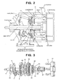
- Fig. 3 shows a portion including the wobble plate rotation preventing mechanism (constant velocity joint mechanism) in the compressor according to the embodiment of the basic structure depicted in Fig. 1 , as an exploded perspective view.
- a compressor 1 has a housing 2 disposed at the central portion, a front housing 3 and a rear housing 4 disposed on both sides of the housing 2 as its housings, and a main shaft 5 inputted with a rotational drive power from outside is provided over the range from the portion of housing 2 up to the position extending through front housing 3.
- a rotor 6 is fixed to main shaft 5 so as to be rotated integrally with main shaft 5, and a swash plate 8 is connected to rotor 6 via a hinge mechanism 7, changeably in angle and rotatably together with main shaft 5.
- Piston 10 is reciprocally inserted into each cylinder bore 9, and piston 10 is connected to wobble plate 12 via connecting rod 11.
- a constant velocity joint mechanism 21 is provided as a rotation preventing mechanism of wobble plate 12 and a power transmission mechanism to wobble plate 12, and in the above-described embodiment, this rotation preventing mechanism (constant velocity joint mechanism) 21 is formed from a mechanism comprising (a) an inner ring 27 provided in housing 2 movably in the axial direction although its rotation is prevented, supporting main shaft 5 via a bearing 22 (radial bearing) at its inner diameter portion to rotate relatively and to move relatively in the axial direction and having a plurality of guide grooves 26 for guiding a plurality of balls 25 provided for power transmission, (b) a sleeve 24 functioning as a wobble central member of the wobble movement of wobble plate 12, provided on main shaft 5 to rotate relatively thereto and to move in the axial direction and engaged with inner ring 27 movably in the axial direction together with inner ring 27, (c) an outer ring 30 having a plurality of guide grooves 28 for guiding balls 25 at positions opposing respective guide grooves 26 of inner ring 27, supported on sle
- Thrust bearings 31, 32 are interposed between wobble plate 12 and swash plate 8 and between rotor 6 and front housing 3, respectively. Further, although inner ring 27 is supported in housing 9 movably in the axial direction, its rotation is prevented. As means for preventing the rotation, a general rotation regulating means such as a key or a spline may be used (not depicted). Furthermore, although the rear end of main shaft 5 is supported by bearing 22 provided on the inner diameter portion of inner ring 27, because main shaft 5 is supported also at the side of front housing 3 through the compression main mechanism portion rotatably via bearing 33 (radial bearing), it is radially supported on both sides (inboard supporting).
- outer ring 30 is wabblingly supported by sleeve 24 through the spherical surface contact, and sleeve 24 is supported by rotational main shaft 5 rotatably and movably in the axial direction, and by this structure, it is possible to make play in the radial direction between rotational main shaft 5 and the whole of the wobble mechanism portion small, thereby improving the reliability and reducing vibration and noise.
- main shaft 5 is supported in the condition of inboard supporting on both sides of the compression main mechanism portion by bearing 22 provided in the inner diameter portion of inner ring 27 and bearing 33 provided on front housing 3 side, a sufficiently high rigidity can be ensured even if the diameter of main shaft 5 is relatively small, the whirling of main shaft 5 can also be suppressed small, making small-sized can be easily achieved, and improvement of reliability and reduction of vibration and noise may be possible. Further, as the result of suppressing the whirling of rotational main shaft 5 small, the whirling of the whole of the rotational portion rotated together with main shaft 5 can also be suppressed to be small, and therefore, the rotational balance of the whole of the rotated portion becomes remarkably good.
- outer ring 30 and wobble plate 12 are formed as members separated from each other and they are fixed to each other, these members may be formed integrally. By this integration, the number of parts may be further reduced and the assembly may be further facilitated.
- the present invention has added a further improvement for the portion of the constant velocity joint mechanism.
- Fig. 5 referring to Fig. 6 , more desirable structure and more desirable setting conditions (in particular, a setting condition where ball 45 will not drop in any case) will be explained in more detail.
- Fig. 6 shows an enlargement diagram of a portion of a single ball 45 and a pair of guide grooves 43, 44 of inner ring 41 and outer ring 42 nipping the ball.
- the radii of the loci formed in case where the respective points of inner ring 41 and outer ring 42 are rotated around the common center of rotation X are represented as follows, and the diameter of ball 45 is represented as D.
- the shapes of respective guide grooves 43, 44 and the diameter D of ball 45 may be set so as to satisfy the above-described equations (1), (2) and (3).
- the number of sets of ball 45/guide grooves 43, 44 can be reduced half from six sets down to three sets. Therefore, while a predetermined power transmission function required to the constant velocity joint mechanism is completely maintained as it is, the number of places to be processed for guide grooves 43, 44 particularly required with precise processing can be greatly reduced (down to half), the cost for processing for structural parts is reduced, and the cost for the constant velocity joint mechanism, ultimately, for the whole of the compressor, can be achieved. Further, by reduction of the number of sets of ball 45/guide grooves 43, 44, reduction of processes for assembly, and cost reduction accompanying therewith, can also be achieved. Furthermore, by reduction of the number of necessary structural portions in the constant velocity joint mechanism, lightening in weight of the constant velocity joint mechanism, ultimately, lightening in weight of the whole of the compressor, also becomes possible.
- the structure of the compressor according to the present invention can be applied to a wobble plate type variable displacement compressor used in any field, and especially, it is suitable for use in the field for vehicles highly requiring making small-sized, increase of reliability, improvement of durability and silent performance, and cost down, in particular, for use in an air conditioning system for vehicles.
Landscapes
- Engineering & Computer Science (AREA)
- General Engineering & Computer Science (AREA)
- Mechanical Engineering (AREA)
- Compressors, Vaccum Pumps And Other Relevant Systems (AREA)
Abstract
Description
- The present invention relates to a compressor, and specifically, to improvement of a variable displacement compressor previously proposed by the applicant of the present application which incorporates therein a new wobble plate rotation preventing mechanism.
- With respect to a compressor having a constant velocity joint mechanism provided as a rotation preventing mechanism for a wobble plate, a wobble plate type variable displacement compressor is previously proposed by the applicant of the present invention which uses a constant velocity joint mechanism small-sized and good in durability and silent performance (Patent document 1). In this proposal, as the rotation preventing mechanism of the wobble plate, a constant velocity joint mechanism is provided, which comprises (a) an inner ring provided in a housing movably in an axial direction although rotation is prevented, supporting a rotational main shaft via a bearing at an inner diameter portion to rotate relatively and to move relatively in an axial direction and having a plurality of guide grooves for guiding a plurality of balls provided for power transmission, (b) a sleeve functioning as a wobble central member of the wobble movement of the wobble plate, provided on the rotational main shaft to rotate relatively thereto and to move in an axial direction and engaged with the inner ring movably in an axial direction together with the inner ring, (c) an outer ring having a plurality of guide grooves for guiding the balls at positions opposing respective guide grooves of the inner ring, supported on the sleeve wabblingly, supporting the wobble plate fixedly on an outer circumference and supporting the swash plate rotatably via a bearing, and (d) a plurality of balls held by the guide grooves formed in the inner ring and the outer ring at a condition of opposing each other and performing power transmission by being compressed between the guide grooves.
- By this proposal, a wobble plate type variable displacement compressor made small-sized, good in durability and silent performance, easy-to-machine and inexpensive, has become possible, but, even in this proposed mechanism, a matter to be further improved is still left. Namely, in the above-described previously proposed mechanism, in the constant velocity joint mechanism, totally six balls of three balls transmitting loaded torque and three balls for maintaining the relative positional relationship between the inner ring side and the outer ring side of the constant velocity joint mechanism at a predetermined positional relationship which do not receive loaded torque are provided, and guide grooves provided in correspondence to these balls are formed at totally six places for the respective inner ring side and outer ring side. Although these guide grooves are formed by processing of cutting, because a precise accuracy for processing is required and the places to be processed are many to be totally six places, there remains a problem that the cost for the processing and the cost for parts accompanied therewith are expensive. Further, since there are many combination mechanism portions of balls and guide grooves retaining them from both sides, there remains a problem that the number of processes for assembly is large and the cost for assembly accompanied therewith is expensive.
-
- Patent document 1:
JP-A-2008-138637 - As described above, in the previously proposed structure described in
Patent document 1, there remains a problem, in particular, that the cost for processing the structural parts is expensive accompanying with many precise processing places, and therefore, a cost reduction is required. - Accordingly, paying attention to the problem left in the above-described previously proposed structure, an object of the present invention is to reduce the cost for a constant velocity joint mechanism, ultimately, the cost for a compressor, by basically abolishing places to be processed except portions required for ensuring functions minimum for structuring parts with respect to the constant velocity joint mechanism. More concretely, although the present invention targets to reduce the cost by abolishing the balls at the side opposite the loaded side of the constant velocity joint mechanism in the previously proposed structure, thereby abolishing the processing of guide grooves corresponding to the abolished balls, as described later using
Fig. 4 , because only by merely abolishing this there may be a problem that the structure for retaining balls by guide grooves at both sides does not stand when a torque is not loaded, an object of the present invention is to provide a particularly improved structure capable of ensuring predetermined functions while solving this problem. - To achieve the above-described objects, a compressor according to the present invention is formed as a wobble plate type variable displacement compressor having a wobble plate which is connected to pistons inserted reciprocally into cylinder bores, in which a rotational movement of a swash plate, rotated together with a main shaft and supported changeably in angle relative to the main shaft, is converted into a wobble movement of the wobble plate, and which transmits the wobble movement to the pistons to reciprocate the pistons, and having a constant velocity joint mechanism as a rotation preventing mechanism of the wobble plate and a power transmission mechanism to the wobble plate, the constant velocity joint mechanism comprising (a) an inner ring provided movably in an axial direction while being prevented with rotation, supporting the main shaft at a radially inner portion rotatably mutually and movably mutually in an axial direction, and having guide grooves for guiding balls provided for power transmission, (b) an outer ring having guide grooves for guiding the balls at positions facing the guide grooves of the inner ring, supporting the wobble plate on an outer circumference of the outer ring and supporting the swash plate rotatably via a bearing, and (c) balls held by the guide grooves formed in the inner ring and the outer ring so as to face one another and performing power transmission by being compressed between the guide grooves, and is characterized in that the guide grooves formed in the inner ring and the outer ring so as to face one another are formed in such a manner that, with respect to a shape in a cross section including a virtual line that links a center of the ball held between the both guide grooves and a common center of rotation of the inner ring and the outer ring, one shoulder part (A) of one of the guide grooves is wrapped around relatively to an outer circumference of the ball so as to exceed the virtual line, and a shoulder part (B) of the other guide groove which is positioned on the opposite side to the shoulder part (A) of the one guide groove via the ball interposed is wrapped around relatively to the outer circumference of the ball so as to exceed the virtual line, respectively, and an amount of wraparound exceeding the virtual line of both shoulder parts (A) and (B) is set at an amount determined such that even if the inner ring and the outer ring are rotated relative to one another in a direction moving away from one another, the ball will not drop from between the both guide grooves.
- Although the details of the aforementioned constant velocity joint mechanism in the structure described in
Patent document 1 previously proposed by the applicant of the present invention will be described later, the main part of the structure having a relation with the present invention can be shown, for example, as shown inFig. 4(A) . Namely,guide grooves inner ring 27 andouter ring 30 of constantvelocity joint mechanism 21, respectively,balls 25 are retained between bothguide grooves guide grooves balls 25 are provided on both sides of the arm portions ofinner ring 27 orouter ring 30. Relatively to this structure, in order to reduce the cost by decreasing the places to be processed that is an object of the present invention, as shown inFig. 4 (B) for example, if a structure ofinner ring 27a andouter ring 30a is employed wherein non-drive side three sets (three places) are simply abolished (removed), in case whereinner ring 27a andouter ring 30a are rotated relative to one another in a direction moving away from one another,balls 25 cannot be retained between both guide grooves, andballs 25 will drop. - Accordingly, in the present invention, as shown in
Fig. 5 ,guide grooves inner ring 41 andouter ring 42 so as to face one another are formed in such a manner that, with respect to the shape in a cross section including avirtual line 48 that links acenter 46 ofball 45 held between bothguide grooves rotation 47 of theinner ring 41 and theouter ring 42, one shoulder part (A) of oneguide groove 43 is wrapped around relatively to the outer circumference ofball 45 so as to exceed thevirtual line 48, and a shoulder part (B) of theother guide groove 44 which is positioned on the opposite side to the shoulder part (A) of the oneguide groove 43 via theball 45 interposed is wrapped around relatively to the outer circumference of theball 45 so as to exceed thevirtual line 48, respectively, and an amount of wraparound exceeding thevirtual line 48 of both shoulder parts (A) and (B) (in the figure, indicated by an angle θ) is set at an amount determined such that even if theinner ring 41 and theouter ring 42 are rotated relative to one another in a direction moving away from one another, theball 45 will not drop from between bothguide grooves ball 45 by a predetermined amount on the basis ofvirtual line 48. By such a structure, while a predetermined power transmission function is ensured wheninner ring 41 andouter ring 42 loaded with a torque are rotated relatively to one another in a direction moving close to one another, wheninner ring 41 andouter ring 42 are rotated relatively to one another in a direction moving away from one another, both shoulder parts (A) and (B) come into contact withball 45 so as to nip theball 45, and therefore, theball 45 itself is prevented from dropping from between bothguide grooves inner ring 41 andouter ring 42 may be always kept. Further, in this improved structure, because the number of sets of combination ofguide grooves balls 45 is reduced down to half, the number of places to be precisely processed is also reduced down to half, the cost for processing these structural parts is reduced, and a cost reduction as a whole can be achieved. Furthermore, by reduction of necessary structural portions, lightening in weight also becomes possible. - In such a compressor according to the present invention, it is preferred that the guide grooves formed in the inner ring and the outer ring so as to face one another and the ball held between both guide grooves are disposed at a plurality of sets in a circumferential direction from balance of a transmitted torque at the time of power transmission, etc., although a structure of one set is possible theoretically. In the structure shown in
Fig. 5 , three sets are disposed in the circumferential direction, and in the structure shown inFig. 7 described later, two sets are disposed in the circumferential direction. With respect to the disposition form in the circumferential direction, disposition at same intervals (at same pitches) is preferable from the viewpoint of balance of transmitted torque, etc. - Further, in the present invention, in order to more securely achieve the structure such that the ball will not drop from between both guide grooves even if the inner ring and the outer ring are rotated relative to one another in a direction moving away from one another, as described later, it is preferred that radii from the above-described common center of rotation of both shoulder parts (A) and (B) corresponding to the above-described amount of wraparound and a diameter of the ball are set at a condition being related to one another. In this case, a clearance between the ball and each guide groove can also be considered.
- Thus, in the compressor according to the present invention, while the merits due to the previously proposed structure described in
Patent document 1, namely, the merits of making the compressor small-sized, improvement of durability and silent performance, improvement of processing performance, reduction of cost, etc. can be ensured, by improvement due to the present invention, because the number of balls and the number of guide grooves can be reduced, the cost of parts can be reduced. Further, because the number of sets of ball/guide groove can be reduced, the number of processes for assembly and the cost therefor can be reduced, and further, lightening in weight may be performed. -
- [
Fig. 1] Fig. 1 is a vertical sectional view of a compressor showing an example of a structure previously proposed by the applicant of the present invention which becomes a basic structure for improvement by the present invention. - [
Fig. 2] Fig. 2 is a vertical sectional view of the compressor depicted inFig. 1 , showing an operational condition different from that depicted inFig. 1 . - [
Fig. 3] Fig. 3 is an exploded perspective view of a portion including a wobble plate rotation preventing mechanism (a constant velocity joint mechanism) of the compressor depicted inFig. 1 . - [
Fig. 4] Fig. 4 shows a schematic diagram of the constant velocity joint mechanism of the compressor depicted inFig. 1 (Fig. 4 (A) ) and a schematic diagram showing an example in case where a part of guide groove processing portions is simply abolished from the constant velocity joint mechanism (Fig. 4 (B) ). - [
Fig. 5] Fig. 5 is a schematic diagram of a constant velocity joint mechanism of a compressor according to an embodiment of the present invention. - [
Fig. 6] Fig. 6 is an explanation diagram showing a principle of the present invention in the constant velocity joint mechanism depicted inFig. 5 . - [
Fig. 7] Fig. 7 is a schematic diagram of a constant velocity joint mechanism of a compressor according to another embodiment of the present invention. - Hereinafter, the present invention will be explained more concretely, together with desirable embodiments.
First, an example of a structure previously proposed by the applicant of the present invention, which becomes a basic structure for improvement by the present invention, will be explained referring toFigs. 1-3 .Fig. 1 shows an example of a basic structure of a wobble plate type variable displacement compressor having a wobble plate rotation preventing mechanism, and shows its entire structure in the operation state at the condition of the displacement achieving its maximum discharge.Fig. 2 shows the operation state of the compressor depicted inFig. 1 at the condition of the displacement achieving its minimum discharge, andFig. 3 shows a portion including the wobble plate rotation preventing mechanism (constant velocity joint mechanism) in the compressor according to the embodiment of the basic structure depicted inFig. 1 , as an exploded perspective view. - In
Figs. 1 and2 , acompressor 1 has ahousing 2 disposed at the central portion, a front housing 3 and a rear housing 4 disposed on both sides of thehousing 2 as its housings, and amain shaft 5 inputted with a rotational drive power from outside is provided over the range from the portion ofhousing 2 up to the position extending through front housing 3. Arotor 6 is fixed tomain shaft 5 so as to be rotated integrally withmain shaft 5, and aswash plate 8 is connected torotor 6 via a hinge mechanism 7, changeably in angle and rotatably together withmain shaft 5. Piston 10 is reciprocally inserted into each cylinder bore 9, andpiston 10 is connected towobble plate 12 via connectingrod 11. The rotational movement ofswash plate 8 is converted into the wobble movement ofwobble plate 12, the wobble movement is transmitted topiston 10 via connectingrod 11, andpiston 10 is reciprocated. Fluid to be compressed (for example, refrigerant) is sucked fromsuction chamber 13 formed in rear housing 4 into cylinder bore 9 throughsuction hole 15 formed on valve plate 14 (a suction valve is omitted in the figure) accompanying with the reciprocating movement ofpiston 10, and after the sucked fluid is compressed, the compressed fluid is discharged intodischarge chamber 17 through discharge hole 16 (a discharge valve is omitted in the figure), and therefrom, sent to an external circuit. - It is necessary that the above-described
wobble plate 12 performs a wobble movement at a condition where its rotation is prevented. Hereinafter, the remaining portions ofcompressor 1 will be explained mainly with respect to the rotation preventing mechanism of thewobble plate 12, which comprises a constant velocity joint mechanism, in reference toFigs. 1 to 3 . - A constant
velocity joint mechanism 21 is provided as a rotation preventing mechanism ofwobble plate 12 and a power transmission mechanism to wobbleplate 12, and in the above-described embodiment, this rotation preventing mechanism (constant velocity joint mechanism) 21 is formed from a mechanism comprising (a) aninner ring 27 provided inhousing 2 movably in the axial direction although its rotation is prevented, supportingmain shaft 5 via a bearing 22 (radial bearing) at its inner diameter portion to rotate relatively and to move relatively in the axial direction and having a plurality ofguide grooves 26 for guiding a plurality ofballs 25 provided for power transmission, (b) asleeve 24 functioning as a wobble central member of the wobble movement ofwobble plate 12, provided onmain shaft 5 to rotate relatively thereto and to move in the axial direction and engaged withinner ring 27 movably in the axial direction together withinner ring 27, (c) anouter ring 30 having a plurality ofguide grooves 28 for guidingballs 25 at positions opposingrespective guide grooves 26 ofinner ring 27, supported onsleeve 24 wabblingly, connected withwobble plate 12 fixedly on its outer circumference and supportingswash plate 8 rotatably via a bearing 29 (radial bearing), and (d) a plurality ofballs 25 held byguide grooves inner ring 27 andouter ring 30 at a condition of opposing each other and performing power transmission by being compressed between bothguide grooves Thrust bearings wobble plate 12 andswash plate 8 and betweenrotor 6 and front housing 3, respectively. Further, althoughinner ring 27 is supported in housing 9 movably in the axial direction, its rotation is prevented. As means for preventing the rotation, a general rotation regulating means such as a key or a spline may be used (not depicted). Furthermore, although the rear end ofmain shaft 5 is supported by bearing 22 provided on the inner diameter portion ofinner ring 27, becausemain shaft 5 is supported also at the side of front housing 3 through the compression main mechanism portion rotatably via bearing 33 (radial bearing), it is radially supported on both sides (inboard supporting). - In
rotation preventing mechanism 21 ofwobble plate 12 constructed as described above,outer ring 30 is wabblingly supported bysleeve 24 through the spherical surface contact, andsleeve 24 is supported by rotationalmain shaft 5 rotatably and movably in the axial direction, and by this structure, it is possible to make play in the radial direction between rotationalmain shaft 5 and the whole of the wobble mechanism portion small, thereby improving the reliability and reducing vibration and noise. Further, in the above-described embodiment, sincemain shaft 5 is supported in the condition of inboard supporting on both sides of the compression main mechanism portion bybearing 22 provided in the inner diameter portion ofinner ring 27 and bearing 33 provided on front housing 3 side, a sufficiently high rigidity can be ensured even if the diameter ofmain shaft 5 is relatively small, the whirling ofmain shaft 5 can also be suppressed small, making small-sized can be easily achieved, and improvement of reliability and reduction of vibration and noise may be possible. Further, as the result of suppressing the whirling of rotationalmain shaft 5 small, the whirling of the whole of the rotational portion rotated together withmain shaft 5 can also be suppressed to be small, and therefore, the rotational balance of the whole of the rotated portion becomes remarkably good. Where, in the above-described structure, it is possible to extendmain shaft 5 rearward and to replace it for a structure being supported directly byhousing 2 via a bearing. Furthermore, in the above-described embodiment, by the engagement of the spherical surface (concave spherical surface) formed in the inner diameter side ofinner ring 27 with the spherical surface (convex spherical surface) formed in the outer diameter side ofsleeve 24, a mutual supporting between both members is performed. By adjusting a clearance in this supporting portion, it is possible to absorb a relative whirling of the inner and outer rings caused by the dispersion of the positions of the guide grooves for a plurality ofballs 25 operating for power transmission, whereby the uniform and continuous contact ofballs 25 is further improved, and it is more advantageous with respect to reliability, vibration and noise. Where, although in the above-described embodimentouter ring 30 andwobble plate 12 are formed as members separated from each other and they are fixed to each other, these members may be formed integrally. By this integration, the number of parts may be further reduced and the assembly may be further facilitated. - On the premise of such a structure, the present invention has added a further improvement for the portion of the constant velocity joint mechanism. Although the principle of the present invention has been already described using
Fig. 5 , referring toFig. 6 , more desirable structure and more desirable setting conditions (in particular, a setting condition whereball 45 will not drop in any case) will be explained in more detail. -
Fig. 6 shows an enlargement diagram of a portion of asingle ball 45 and a pair ofguide grooves inner ring 41 andouter ring 42 nipping the ball. The radii of the loci formed in case where the respective points ofinner ring 41 andouter ring 42 are rotated around the common center of rotation X are represented as follows, and the diameter ofball 45 is represented as D. - Ri1: radius up to shoulder part A point of
guide groove 43 ofinner ring 41 - Ri2: radius up to maximum distance point E of
guide groove 43 ofinner ring 41 with whichball 45 can comes into contact - Ro1: radius up to shoulder part B point of
guide groove 44 ofouter ring 42 - Ro2: radius up to minimum distance point F of
guide groove 44 ofouter ring 42 with whichball 45 can comes into contact - In order to achieve a condition where
ball 45 will not drop even ifinner ring 41 andouter ring 42 are rotated relative to one another in a direction moving away from one another, first, a distance between radii of shoulder part A and shoulder part B [Ri1 - Ro1] must be smaller than diameter of ball D. Therefore, the following equation must be satisfied.
- Further, even if the above-described equation (1) is satisfied, depending upon a clearance between
ball 45 and eachguide groove ball 45 will drop). Therefore, it is necessary to satisfy the following equation as a restriction whenball 45 is in a condition coming into contact with point E.
Similarly, it is necessary to satisfy the following equation as a restriction whenball 45 is in a condition coming into contact with point F.
- Therefore, in order to achieve a condition where
ball 45 will not drop even ifinner ring 41 andouter ring 42 are rotated relative to one another in a direction moving away from one another, the shapes ofrespective guide grooves ball 45 may be set so as to satisfy the above-described equations (1), (2) and (3). By employing such setting conditions, the dropping ofball 45 can be surely prevented in consideration of conditions up to the clearances betweenball 45 and therespective guide grooves - Consequently, at a state preventing the dropping of
ball 45 and always keeping the combination between the ball and guidegrooves ball 45/guide grooves guide grooves ball 45/guide grooves - Although three sets of
ball 45/guide grooves Fig. 5 , disposition of more than three sets is possible, and further, as shown inFig. 7 , disposition of two sets of ball/guide grooves is also possible. In case of two sets, as shown inFig. 7 , it is preferred that the sets ofrespective guide grooves inner ring 51 andouter ring 52 andballs 55 provided between both guidegrooves virtual line 56 of the shoulder parts ofguide grooves - The structure of the compressor according to the present invention can be applied to a wobble plate type variable displacement compressor used in any field, and especially, it is suitable for use in the field for vehicles highly requiring making small-sized, increase of reliability, improvement of durability and silent performance, and cost down, in particular, for use in an air conditioning system for vehicles.
-
- 1: compressor
- 2: housing
- 3: front housing
- 4: rear housing
- 5: main shaft
- 5a: center axis
- 6: rotor
- 7: hinge mechanism
- 8: swash plate
- 9: cylinder bore
- 10: piston
- 11: connecting rod
- 12: wobble plate
- 13: suction chamber
- 14: valve plate
- 15: suction hole
- 16: discharge hole
- 17: discharge chamber
- 21: rotation preventing mechanism of wobble plate (constant velocity joint mechanism)
- 22, 23, 29, 33: bearing (radial bearing)
- 24: sleeve
- 25: ball
- 26: guide groove of inner ring
- 27: inner ring
- 27a: inner ring in case where a part of processing for guide grooves is simply abolished
- 28: guide groove of outer ring
- 30: outer ring
- 30a: outer ring in case where a part of processing for guide grooves is simply abolished
- 31, 32: thrust bearing
- 41, 51: inner ring
- 42, 52: outer ring
- 43, 53: guidegroove formed on inner ring
- 44, 54: guide groove formed on outer ring
- 45, 55: ball
- 46: center of ball
- 47: common center of rotation of inner ring and outer ring
- 48, 56: virtual line
- A, B: shoulder part
- X: common center of rotation
Claims (3)
- A compressor formed as a wobble plate type variable displacement compressor having a wobble plate which is connected to pistons inserted reciprocally into cylinder bores, in which a rotational movement of a swash plate, rotated together with a main shaft and supported changeably in angle relative to said main shaft, is converted into a wobble movement of said wobble plate, and which transmits said wobble movement to said pistons to reciprocate said pistons, and having a constant velocity joint mechanism as a rotation preventing mechanism of said wobble plate and a power transmission mechanism to said wobble plate, said constant velocity joint mechanism comprising (a) an inner ring provided movably in an axial direction while being prevented with rotation, supporting said main shaft at a radially inner portion rotatably mutually and movably mutually in an axial direction, and having guide grooves for guiding balls provided for power transmission, (b) an outer ring having guide grooves for guiding said balls at positions facing said guide grooves of said inner ring, supporting said wobble plate on an outer circumference of said outer ring and supporting said swash plate rotatably via a bearing, and (c) balls held by said guide grooves formed in said inner ring and said outer ring so as to face one another and performing power transmission by being compressed between said guide grooves, characterized in that:said guide grooves formed in said inner ring and said outer ring so as to face one another are formed in such a manner that, with respect to a shape in a cross section including a virtual line that links a center of said ball held between said both guide grooves and a common center of rotation of said inner ring and said outer ring, one shoulder part (A) of one of said guide grooves is wrapped around relatively to an outer circumference of said ball so as to exceed said virtual line, and a shoulder part (B) of the other guide groove which is positioned on the opposite side to said shoulder part (A) of said one guide groove via said ball interposed is wrapped around relatively to said outer circumference of said ball so as to exceed said virtual line, respectively, and an amount of wraparound exceeding said virtual line of both shoulder parts (A) and (B) is set at an amount determined such that even if said inner ring and said outer ring are rotated relative to one another in a direction moving away from one another, said ball will not drop from between said both guide grooves.
- The compressor according to claim 1, wherein said guide grooves formed in said inner ring and said outer ring so as to face one another and said ball held between both guide grooves are disposed at a plurality of sets in a circumferential direction.
- The compressor according to claim 1 or 2, wherein, in order to form so that said ball will not drop from between said both guide grooves even if said inner ring and said outer ring are rotated relative to one another in a direction moving away from one another, radii from said common center of rotation of said both shoulder parts (A) and (B) corresponding to said amount of wraparound and a diameter of said ball are set at a condition being related to one another.
Applications Claiming Priority (2)
| Application Number | Priority Date | Filing Date | Title |
|---|---|---|---|
| JP2010016708A JP2011153592A (en) | 2010-01-28 | 2010-01-28 | Compressor |
| PCT/JP2011/000457 WO2011093084A1 (en) | 2010-01-28 | 2011-01-27 | Compressor |
Publications (2)
| Publication Number | Publication Date |
|---|---|
| EP2525096A1 true EP2525096A1 (en) | 2012-11-21 |
| EP2525096A4 EP2525096A4 (en) | 2013-07-24 |
Family
ID=44319078
Family Applications (1)
| Application Number | Title | Priority Date | Filing Date |
|---|---|---|---|
| EP11736799.5A Withdrawn EP2525096A4 (en) | 2010-01-28 | 2011-01-27 | Compressor |
Country Status (4)
| Country | Link |
|---|---|
| EP (1) | EP2525096A4 (en) |
| JP (1) | JP2011153592A (en) |
| CN (1) | CN102741553A (en) |
| WO (1) | WO2011093084A1 (en) |
Families Citing this family (3)
| Publication number | Priority date | Publication date | Assignee | Title |
|---|---|---|---|---|
| CN103591158A (en) * | 2013-11-28 | 2014-02-19 | 青岛科技大学 | Three-fork-lever double-faced steel ball type constant-angular-velocity universal coupling |
| JP6470086B2 (en) * | 2015-03-31 | 2019-02-13 | サンデンホールディングス株式会社 | Swing plate type variable capacity compressor |
| CN119308941B (en) * | 2024-12-18 | 2025-03-18 | 德州学院 | Universal joint convenient to disassemble and assemble for hanging |
Family Cites Families (7)
| Publication number | Priority date | Publication date | Assignee | Title |
|---|---|---|---|---|
| DE2331033A1 (en) * | 1973-06-19 | 1975-01-16 | Daimler Benz Ag | Synchronising coupling for final drive of vehicles - uses spheres with ball bearings running in grooves of specified shape |
| FR2492484A2 (en) * | 1980-10-21 | 1982-04-23 | Devos Gaston | HOMOCINETIC UNIVERSAL JOINT |
| US5129752A (en) * | 1990-04-05 | 1992-07-14 | General Motors Corporation | Rzeppa joint socket plate torque restraint assembly for a variable displacement compressor |
| US5112197A (en) * | 1990-10-01 | 1992-05-12 | General Motors Corporation | Cross groove joint socket plate torque restraint assembly for a variable displacement compressor |
| US5509346A (en) * | 1995-05-30 | 1996-04-23 | General Motors Corporation | Variable displacement compressor with simplified torque restraint |
| JP2005307942A (en) * | 2004-04-26 | 2005-11-04 | Denso Corp | Swing swash plate type variable capacity compressor |
| JP4829761B2 (en) * | 2006-12-05 | 2011-12-07 | サンデン株式会社 | Swing plate type variable capacity compressor |
-
2010
- 2010-01-28 JP JP2010016708A patent/JP2011153592A/en active Pending
-
2011
- 2011-01-27 WO PCT/JP2011/000457 patent/WO2011093084A1/en not_active Ceased
- 2011-01-27 CN CN2011800075214A patent/CN102741553A/en active Pending
- 2011-01-27 EP EP11736799.5A patent/EP2525096A4/en not_active Withdrawn
Also Published As
| Publication number | Publication date |
|---|---|
| CN102741553A (en) | 2012-10-17 |
| EP2525096A4 (en) | 2013-07-24 |
| WO2011093084A1 (en) | 2011-08-04 |
| JP2011153592A (en) | 2011-08-11 |
Similar Documents
| Publication | Publication Date | Title |
|---|---|---|
| EP2119911B1 (en) | Oscillatory plate type variable capacity compressor | |
| US20090007773A1 (en) | Axial plunger pump or motor | |
| US9228573B2 (en) | Wabble plate type variable displacement compressor | |
| US8757045B2 (en) | Wobble plate type variable displacement compressor | |
| EP2306014B1 (en) | Wobble plate type variable displacement compressor | |
| EP2306015B1 (en) | Wobble plate type variable displacement compressor | |
| JP4656666B2 (en) | Swash ring compressor | |
| US8783161B2 (en) | Wobble plate type variable displacement compressor | |
| WO2011093084A1 (en) | Compressor | |
| US20180051682A1 (en) | Wobble Plate Type Variable Displacement Compressor | |
| CN108026894A (en) | Inclined shaft type hydraulic pump motor | |
| JP4451323B2 (en) | Link mechanism and variable capacity compressor using the same | |
| JP2012177358A (en) | Swing plate type variable displacement compressor | |
| JP2006125222A (en) | Swing support mechanism | |
| KR20110107155A (en) | Twist yoke of swash plate piston pump |
Legal Events
| Date | Code | Title | Description |
|---|---|---|---|
| PUAI | Public reference made under article 153(3) epc to a published international application that has entered the european phase |
Free format text: ORIGINAL CODE: 0009012 |
|
| 17P | Request for examination filed |
Effective date: 20120813 |
|
| AK | Designated contracting states |
Kind code of ref document: A1 Designated state(s): AL AT BE BG CH CY CZ DE DK EE ES FI FR GB GR HR HU IE IS IT LI LT LU LV MC MK MT NL NO PL PT RO RS SE SI SK SM TR |
|
| DAX | Request for extension of the european patent (deleted) | ||
| A4 | Supplementary search report drawn up and despatched |
Effective date: 20130620 |
|
| RIC1 | Information provided on ipc code assigned before grant |
Ipc: F04B 27/10 20060101ALI20130614BHEP Ipc: F16D 3/22 20060101AFI20130614BHEP |
|
| STAA | Information on the status of an ep patent application or granted ep patent |
Free format text: STATUS: THE APPLICATION IS DEEMED TO BE WITHDRAWN |
|
| 18D | Application deemed to be withdrawn |
Effective date: 20140121 |