EP2525045A2 - Blade outer air seal for a gas turbine engine having non-parallel segment confronting faces - Google Patents
Blade outer air seal for a gas turbine engine having non-parallel segment confronting faces Download PDFInfo
- Publication number
- EP2525045A2 EP2525045A2 EP12159865A EP12159865A EP2525045A2 EP 2525045 A2 EP2525045 A2 EP 2525045A2 EP 12159865 A EP12159865 A EP 12159865A EP 12159865 A EP12159865 A EP 12159865A EP 2525045 A2 EP2525045 A2 EP 2525045A2
- Authority
- EP
- European Patent Office
- Prior art keywords
- gap width
- confronting
- operating point
- engine operating
- seal
- Prior art date
- Legal status (The legal status is an assumption and is not a legal conclusion. Google has not performed a legal analysis and makes no representation as to the accuracy of the status listed.)
- Withdrawn
Links
- 239000007789 gas Substances 0.000 description 22
- 239000000112 cooling gas Substances 0.000 description 15
- 238000001816 cooling Methods 0.000 description 2
- 230000001066 destructive effect Effects 0.000 description 2
- 241000270299 Boa Species 0.000 description 1
- 150000001875 compounds Chemical class 0.000 description 1
- 230000007423 decrease Effects 0.000 description 1
- 230000003247 decreasing effect Effects 0.000 description 1
- 239000000463 material Substances 0.000 description 1
- 230000000284 resting effect Effects 0.000 description 1
- 238000011144 upstream manufacturing Methods 0.000 description 1
Images

Classifications
-
- F—MECHANICAL ENGINEERING; LIGHTING; HEATING; WEAPONS; BLASTING
- F01—MACHINES OR ENGINES IN GENERAL; ENGINE PLANTS IN GENERAL; STEAM ENGINES
- F01D—NON-POSITIVE DISPLACEMENT MACHINES OR ENGINES, e.g. STEAM TURBINES
- F01D11/00—Preventing or minimising internal leakage of working-fluid, e.g. between stages
- F01D11/08—Preventing or minimising internal leakage of working-fluid, e.g. between stages for sealing space between rotor blade tips and stator
-
- F—MECHANICAL ENGINEERING; LIGHTING; HEATING; WEAPONS; BLASTING
- F01—MACHINES OR ENGINES IN GENERAL; ENGINE PLANTS IN GENERAL; STEAM ENGINES
- F01D—NON-POSITIVE DISPLACEMENT MACHINES OR ENGINES, e.g. STEAM TURBINES
- F01D11/00—Preventing or minimising internal leakage of working-fluid, e.g. between stages
- F01D11/005—Sealing means between non relatively rotating elements
-
- F—MECHANICAL ENGINEERING; LIGHTING; HEATING; WEAPONS; BLASTING
- F01—MACHINES OR ENGINES IN GENERAL; ENGINE PLANTS IN GENERAL; STEAM ENGINES
- F01D—NON-POSITIVE DISPLACEMENT MACHINES OR ENGINES, e.g. STEAM TURBINES
- F01D9/00—Stators
- F01D9/02—Nozzles; Nozzle boxes; Stator blades; Guide conduits, e.g. individual nozzles
- F01D9/04—Nozzles; Nozzle boxes; Stator blades; Guide conduits, e.g. individual nozzles forming ring or sector
Definitions
- This disclosure relates generally to a blade outer air seal for a gas turbine engine and, more particularly, to a blade outer air seal having non-parallel segment confronting faces.
- a typical turbine stage assembly for a gas turbine engine includes a blade outer air seal disposed between a rotor stage and a turbine assembly case.
- the air seal is used to prevent or reduce gas path leakage over tips of rotor blades in the rotor stage.
- Such an air seal typically includes a plurality of arcuate seal segments, each of which extends between opposite confronting faces. The confronting faces of adjacent seal segments are separated by an intersegment gap.
- a blade outer air seal for a gas turbine engine.
- the air seal includes an arcuate first seal segment and an arcuate second seal segment.
- the first seal segment extends circumferentially to a first confronting face.
- the second seal segment extends circumferentially to a second confronting face.
- the first confronting face is positioned adjacent the second confronting face defining a gap therebetween.
- the confronting faces are radially non-parallel at a first engine operating point where each seal segment has a first temperature distribution profile and a first pressure distribution profile.
- the confronting faces are substantially radially parallel at a second engine operating point where each seal segment has a second temperature distribution profile and a second pressure distribution profile, which second profiles are different than the first profiles.
- another blade outer air seal for a gas turbine engine.
- the air seal includes an arcuate first seal segment and an arcuate second seal segment.
- the first seal segment extends circumferentially to a first confronting face.
- the second seal segment extends circumferentially to a second confronting face.
- the first confronting face is positioned adjacent the second confronting face defining a gap therebetween.
- the gap varies radially at a first engine operating point where each seal segment has a first temperature distribution profile and a first pressure distribution profile.
- the gap is substantially radially uniform at a second engine operating point where each seal segment has a second temperature distribution profile and a second pressure distribution profile, which second profiles are different than the first profiles.
- still another blade outer air seal for a gas turbine engine.
- the air seal includes an arcuate first seal segment and an arcuate second seal segment.
- the first seal segment extends circumferentially to a first confronting face.
- the second seal segment extends circumferentially to a second confronting face.
- the first confronting face is positioned adjacent the second confronting face defining a gap therebetween.
- the gap has a radially inner gap width and a radially outer gap width.
- the inner gap width is greater than the outer gap width at a first engine operating point where each seal segment has a first temperature distribution profile and a first pressure distribution profile.
- the inner gap width is substantially equal to the outer gap width at a second engine operating point where each seal segment has a second temperature distribution profile and a second pressure distribution profile, which second profiles are different than the first profiles.
- the assembly 10 includes a rotor blade stage 12, a stator vane stage 14, a blade outer air seal 16 (sometimes also referred to as a "BOAS") and a turbine support case 18.
- the rotor blade stage 12 includes a plurality of rotor blades 20 circumferentially disposed around a rotor disk 22.
- the stator vane stage 14 includes a plurality of stator vanes 24 circumferentially disposed between inner and outer vane platforms 26 and 28.
- the stator vanes 24 are located downstream of the rotor blades 20 in a hot gas flow path 30 (sometimes also referred to as a "working gas flow path").
- the blade outer air seal 16 is located radially between the rotor blades 20 and the support case 18, and is connected to the support case 18 via a plurality of mounting flanges 32 and 34.
- the support case 18 houses the rotor blade stage 12, the stator vane stage 14, and the blade outer air seal 16.
- the support case 18 includes a cooling gas flow path 36 that is configured to allow cooling air (e.g., from a compressor section of the engine) to pass there through and into a cooling gas plenum 38 located between the blade outer air seal 16 and the support case 18.
- the blade outer air seal 16 includes a plurality of arcuate seal segments 40 and 42.
- Each seal segment 40, 42 extends axially between an upstream end 44 and a downstream end 46 (see FIG. 1 ).
- Each seal segment 40, 42 extends radially between a gas path surface 48 and a cooling gas surface 50.
- each seal segment 40, 42 extends circumferentially between a first confronting face 52 at a first segment end 54 and a second confronting face 56 at a second segment end 58.
- the first confronting face 52 extends between an inner radial end 60 and an outer radial end 64.
- the second confronting face 56 extends between an inner radial end 62 and an outer radial end 66.
- the first confronting face 52 is defined by circumferentially outer surfaces 68 of a pair of axially extending rails, which define a groove 70 therebetween.
- the groove 70 is provided, for example, as an outlet flow path for cooling air that is distributed through the seal segment from the cooling gas plenum 38.
- adjacent seal segments 40 and 42 in the blade outer air seal 16 are arranged such that the first confronting face 52 of a first one of the adjacent seal segments 40 (hereinafter the "first seal segment”) is positioned adjacent the second confronting face 56 of a second one of the adjacent seal segments 42 (hereinafter the "second seal segment”) defining an intersegment gap 72 therebetween.
- the gap 72 has an inner radial gap width 74 and an outer radial gap width 76.
- the inner radial gap width 74 extends circumferentially between the inner ends 60 and 62 of the first and second confronting faces 52 and 56.
- the outer radial gap width 76 extends circumferentially between the outer ends 64 and 66 of the first and second confronting faces 52 and 56.
- the gap 72 is provided to prevent or substantially reduce destructive interference between the seal segments 40 and 42 caused by seal segment deformation, while also reducing or preventing gas leakage therethrough.
- each seal segment 40, 42 can be subject to thermal deformation during engine operation.
- Relatively hot working gas for example, is directed through the hot gas flow path 30, and relatively cool cooling gas is directed into the cooling gas plenum 38.
- the hot gas surface 48 of each seal segment 40, 42 therefore is subject to relatively high temperatures, whereas the cooling gas surface 50 is subject to relatively low temperatures.
- This temperature differential between the surfaces 48 and 50 defines a temperature distribution profile for each seal segment 40, 42.
- the term "temperature distribution profile" is used herein to describe at least a radial component of a temperature gradient through each seal segment 40, 42; i.e., a radial temperature gradient between the hot gas surface 48 and the cooling gas surface 50.
- the temperature differential can cause thermal expansion and/or thermal warping of the seal segments 40 and 42 depending on the temperature distribution profile.
- Thermal expansion can increase a circumferential width 77 of each seal segment between the first and the second confronting faces 52 and 56.
- Thermal warping can reduce the curvature of (e.g., flatten) each seal segment.
- each seal segment 40, 42 can also be subject to pressure deformation during engine operation.
- the working gas directed through the hot gas flow path 30, for example, is typically provided at a lower pressure than the cooling gas directed into the cooling gas plenum 38.
- a differential pressure force therefore is exerted by the cooling gas onto the cooling gas surface 50 of each seal segment 40, 42.
- the term "differential pressure force” is used herein to describe a pressure force that results from a pressure differential between the working gas and the cooling gas. Referring to FIG.
- the differential pressure force can cause, for example, the first and the second confronting faces 52 and 56 to warp (e.g., turn) radially inwards or outwards, depending on the configuration of the mounting flanges 32 and 34 and, in particular, which mounting flanges bear the greatest loads and/or act as pivot points.
- FIG. 5A for example, where a seal segment 78 is centrally supported by mounting flanges 80, a pressure force exerted into the page against the segment 78 will cause its edges 82 and 84 to warp into the page since a majority of the force is acting on the segment 78 outside of a central triangular region 86.
- the seal segments 40 and 42 are configured such that the gap 72 has a non-uniform radial cross-sectional geometry at a first engine operating point (see FIG. 4A ), and a substantially uniform radial cross-sectional geometry at a second engine operating point (see FIG. 4B ).
- the seal segments 40 and 42 can be designed for relatively high or maximum performance at the second engine operating point.
- the seal segments 40 and 42 for example, can be configured to significantly reduce or minimize gas leakage through the gap 72 at the second engine operating point, while still preventing destructive interference between adjacent segments.
- first engine operating point is where the engine is resting or is operating at a relatively low power setting (e.g., during taxiing or cruising).
- second engine operating point is where the engine is operating at a relatively high or maximum power setting (e.g., during takeoff).
- Each seal segment 40, 42 has a first temperature distribution profile and a first pressure distribution profile at the first engine operating point.
- Each seal segment 40, 42 has a second temperature distribution profile and a second pressure distribution profile at the second engine operating point, which second profiles are different than the first profiles.
- the gap 72 has the non-uniform radial cross-sectional geometry where the first confronting face 52 of the first seal segment 40 is radially non-parallel to the second confronting face 56 of the second seal segment 42.
- the outer end 64 of the first confronting face 52 extends circumferentially beyond its inner end 60 such the first confronting face 52 has a substantially linear cross-sectional geometry that is skewed, via an offset angle ⁇ , relative to a substantially linear cross-sectional geometry of the second confronting face 56.
- suitable offset angles ⁇ range from, for example, approximately 1 to 20 degrees.
- the inner gap width 74 therefore is greater than the outer gap width 76.
- the present invention is not limited to the aforesaid linear confronting faces.
- at least one of the confronting faces can have a non-linear (e.g., a parabolic, logarithmic, compound, etc.) cross-sectional geometry designed, for example, as a function of the seal segments' material expansion and strength properties.
- the gap 72 has the substantially uniform radial cross-sectional geometry where the first confronting face 52 of the first seal segment 40 is substantially radially parallel to the second confronting face 56 of the second seal segment 42.
- the first confronting face 52 has a substantially linear cross-sectional geometry that is substantially parallel to a substantially linear cross-sectional geometry of the second confronting face 56.
- the inner gap width 74 therefore is substantially equal to the outer gap width 76.
- the confronting faces can have substantially parallel, non-linear cross-sectional geometries (e.g., uniform curving lines, etc.).
- the seal segments 40 and 42 can be subject to thermal and pressure deformation (e.g., thermal expansion, thermal warping, pressure warping, etc.) as described above where, for example, the power setting is increased from the first engine operating point to the second engine operating point.
- the inner ends 60 and 62 of the confronting faces 52 and 56 for example, circumferentially expand at a faster rate than the outer ends 64 and 66 as the temperature differential increases between the hot gas and cooling gas surfaces 48 and 50 (see FIG. 1 ).
- the difference in the magnitude of the thermal expansion can (i) cause adjacent confronting faces 52 and 56 to pivot towards each other, and (ii) flatten the curvature of each seal segment 40, 42.
- the flattening of the curvature can be at least partially reduced where, for example, the differential pressure force acting on the cooling gas surface 50 (see FIG. 1 ) increases and thereby forces the first and the second segment ends 54 and 58 radially inwards.
- the combination of such thermal and pressure deformation therefore can change the cross-sectional geometry of the gap 72 from, for example, the non-parallel geometry shown in FIG. 4A at the first engine operating point to the substantially parallel geometry shown in FIG. 4B at the second engine operating point.
- the deformation In addition to aligning the first and the second confronting faces 52 and 56 as shown in FIG. 4B , the deformation also decreases a minimum gap width between the adjacent seal segments.
- minimum gap width is used herein to describe the smallest circumferential distance between adjacent confronting faces. Referring to FIG. 4A , for example, the minimum gap width is equal to the outer gap width 76. Referring to FIG. 4B , the minimum gap width is equal to the inner and the outer gap widths 74 and 76.
Landscapes
- Engineering & Computer Science (AREA)
- Mechanical Engineering (AREA)
- General Engineering & Computer Science (AREA)
- Turbine Rotor Nozzle Sealing (AREA)
- Gasket Seals (AREA)
Abstract
Description
- This disclosure relates generally to a blade outer air seal for a gas turbine engine and, more particularly, to a blade outer air seal having non-parallel segment confronting faces.
- A typical turbine stage assembly for a gas turbine engine includes a blade outer air seal disposed between a rotor stage and a turbine assembly case. The air seal is used to prevent or reduce gas path leakage over tips of rotor blades in the rotor stage. Such an air seal typically includes a plurality of arcuate seal segments, each of which extends between opposite confronting faces. The confronting faces of adjacent seal segments are separated by an intersegment gap.
- According to one aspect of the invention, a blade outer air seal is provided for a gas turbine engine. The air seal includes an arcuate first seal segment and an arcuate second seal segment. The first seal segment extends circumferentially to a first confronting face. The second seal segment extends circumferentially to a second confronting face. The first confronting face is positioned adjacent the second confronting face defining a gap therebetween. The confronting faces are radially non-parallel at a first engine operating point where each seal segment has a first temperature distribution profile and a first pressure distribution profile. The confronting faces are substantially radially parallel at a second engine operating point where each seal segment has a second temperature distribution profile and a second pressure distribution profile, which second profiles are different than the first profiles.
- According to another aspect of the invention, another blade outer air seal is provided for a gas turbine engine. The air seal includes an arcuate first seal segment and an arcuate second seal segment. The first seal segment extends circumferentially to a first confronting face. The second seal segment extends circumferentially to a second confronting face. The first confronting face is positioned adjacent the second confronting face defining a gap therebetween. The gap varies radially at a first engine operating point where each seal segment has a first temperature distribution profile and a first pressure distribution profile. The gap is substantially radially uniform at a second engine operating point where each seal segment has a second temperature distribution profile and a second pressure distribution profile, which second profiles are different than the first profiles.
- According to another aspect of the invention, still another blade outer air seal is provided for a gas turbine engine. The air seal includes an arcuate first seal segment and an arcuate second seal segment. The first seal segment extends circumferentially to a first confronting face. The second seal segment extends circumferentially to a second confronting face. The first confronting face is positioned adjacent the second confronting face defining a gap therebetween. The gap has a radially inner gap width and a radially outer gap width. The inner gap width is greater than the outer gap width at a first engine operating point where each seal segment has a first temperature distribution profile and a first pressure distribution profile. The inner gap width is substantially equal to the outer gap width at a second engine operating point where each seal segment has a second temperature distribution profile and a second pressure distribution profile, which second profiles are different than the first profiles.
- The foregoing features and the operation of the invention will become more apparent in light of the following description and the accompanying drawings.
-
-
FIG. 1 is a side-sectional diagrammatic illustration of a section of a turbine stage assembly that includes a blade outer air seal. -
FIG. 2 is a diagrammatic illustration of a seal segment included in the air seal shown inFIG. 1 . -
FIG. 3 is a diagrammatic illustration of adjacent ends of first and second seal segments included in the air seal shown inFIG. 1 . -
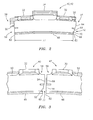
FIG. 4A is a cross-sectional, partial diagrammatic illustration of confronting faces of first and second seal segments at a first engine operating point. -
FIG. 4B is a cross-sectional, partial diagrammatic illustration of the confronting faces shown inFIG. 4A at a second engine operating point. -
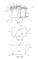
FIG. 5A is a top view of a seal segment that is centrally supported by mounting flanges. -
FIG. 5B is a top view of a seal segment that is supported by mounting flanges at its center and edges. - Referring to
FIG. 1 , a section of aturbine stage assembly 10 is shown for a gas turbine engine. Theassembly 10 includes arotor blade stage 12, astator vane stage 14, a blade outer air seal 16 (sometimes also referred to as a "BOAS") and aturbine support case 18. Therotor blade stage 12 includes a plurality ofrotor blades 20 circumferentially disposed around arotor disk 22. Thestator vane stage 14 includes a plurality ofstator vanes 24 circumferentially disposed between inner andouter vane platforms stator vanes 24 are located downstream of therotor blades 20 in a hot gas flow path 30 (sometimes also referred to as a "working gas flow path"). The bladeouter air seal 16 is located radially between therotor blades 20 and thesupport case 18, and is connected to thesupport case 18 via a plurality ofmounting flanges support case 18 houses therotor blade stage 12, thestator vane stage 14, and the bladeouter air seal 16. Thesupport case 18 includes a coolinggas flow path 36 that is configured to allow cooling air (e.g., from a compressor section of the engine) to pass there through and into acooling gas plenum 38 located between the bladeouter air seal 16 and thesupport case 18. - Referring to
FIGS. 1 to 3 , the bladeouter air seal 16 includes a plurality ofarcuate seal segments seal segment upstream end 44 and a downstream end 46 (seeFIG. 1 ). Eachseal segment gas path surface 48 and acooling gas surface 50. Referring toFIGS. 2 and 3 , eachseal segment face 52 at afirst segment end 54 and a second confrontingface 56 at asecond segment end 58. The first confrontingface 52 extends between an innerradial end 60 and an outerradial end 64. The second confrontingface 56 extends between an innerradial end 62 and an outerradial end 66. In the specific embodiment shown inFIG. 2 , the first confrontingface 52 is defined by circumferentiallyouter surfaces 68 of a pair of axially extending rails, which define a groove 70 therebetween. The groove 70 is provided, for example, as an outlet flow path for cooling air that is distributed through the seal segment from thecooling gas plenum 38. - Referring to
FIG. 3 ,adjacent seal segments outer air seal 16 are arranged such that the first confrontingface 52 of a first one of the adjacent seal segments 40 (hereinafter the "first seal segment") is positioned adjacent the second confrontingface 56 of a second one of the adjacent seal segments 42 (hereinafter the "second seal segment") defining anintersegment gap 72 therebetween. Referring toFIGS. 4A and 4B , thegap 72 has an innerradial gap width 74 and an outerradial gap width 76. The innerradial gap width 74 extends circumferentially between the inner ends 60 and 62 of the first and second confronting faces 52 and 56. The outerradial gap width 76 extends circumferentially between the outer ends 64 and 66 of the first and second confronting faces 52 and 56. Thegap 72 is provided to prevent or substantially reduce destructive interference between theseal segments - Referring to
FIGS. 1 and2 , eachseal segment gas flow path 30, and relatively cool cooling gas is directed into the coolinggas plenum 38. Thehot gas surface 48 of eachseal segment gas surface 50 is subject to relatively low temperatures. This temperature differential between thesurfaces seal segment seal segment hot gas surface 48 and the coolinggas surface 50. Referring toFIG. 2 , the temperature differential can cause thermal expansion and/or thermal warping of theseal segments circumferential width 77 of each seal segment between the first and the second confronting faces 52 and 56. Thermal warping can reduce the curvature of (e.g., flatten) each seal segment. - Referring again to
FIGS. 1 and2 , eachseal segment gas flow path 30, for example, is typically provided at a lower pressure than the cooling gas directed into the coolinggas plenum 38. A differential pressure force therefore is exerted by the cooling gas onto the coolinggas surface 50 of eachseal segment FIG. 2 , the differential pressure force can cause, for example, the first and the second confronting faces 52 and 56 to warp (e.g., turn) radially inwards or outwards, depending on the configuration of the mountingflanges FIG. 5A , for example, where aseal segment 78 is centrally supported by mountingflanges 80, a pressure force exerted into the page against thesegment 78 will cause itsedges segment 78 outside of a central triangular region 86. Referring toFIG. 5B , where aseal segment 88 is supported by mountingflanges 90 at its center and edges, on the other hand, a pressure force exerted into the page against thesegment 88 will cause itsupper corners 92 to warp out of the page since a majority of the force is acting on thesegment 88 within a centraltriangular region 94. The differential pressure force in combination with the configuration of the mounting flanges defines a pressure distribution profile for each seal segment. The term "pressure distribution profile" is used herein to describe how a seal segment deforms in response to a differential pressure force applied thereon. - Referring to
FIGS. 4A and 4B , in order to compensate for such thermal and pressure deformation while reducing gas leakage through thegap 72, theseal segments gap 72 has a non-uniform radial cross-sectional geometry at a first engine operating point (seeFIG. 4A ), and a substantially uniform radial cross-sectional geometry at a second engine operating point (seeFIG. 4B ). In this manner, theseal segments seal segments gap 72 at the second engine operating point, while still preventing destructive interference between adjacent segments. An example of a first engine operating point is where the engine is resting or is operating at a relatively low power setting (e.g., during taxiing or cruising). An example of a second engine operating point is where the engine is operating at a relatively high or maximum power setting (e.g., during takeoff). Eachseal segment seal segment - Referring to
FIG. 4A , thegap 72 has the non-uniform radial cross-sectional geometry where the first confrontingface 52 of thefirst seal segment 40 is radially non-parallel to the second confrontingface 56 of thesecond seal segment 42. In the specific embodiment shown inFIG. 4A , for example, theouter end 64 of the first confrontingface 52 extends circumferentially beyond itsinner end 60 such the first confrontingface 52 has a substantially linear cross-sectional geometry that is skewed, via an offset angle θ, relative to a substantially linear cross-sectional geometry of the second confrontingface 56. Examples of suitable offset angles θ range from, for example, approximately 1 to 20 degrees. Theinner gap width 74 therefore is greater than theouter gap width 76. The present invention, however, is not limited to the aforesaid linear confronting faces. In alternative embodiments, for example, at least one of the confronting faces can have a non-linear (e.g., a parabolic, logarithmic, compound, etc.) cross-sectional geometry designed, for example, as a function of the seal segments' material expansion and strength properties. - Referring to
FIG. 4B , thegap 72 has the substantially uniform radial cross-sectional geometry where the first confrontingface 52 of thefirst seal segment 40 is substantially radially parallel to the second confrontingface 56 of thesecond seal segment 42. In the specific embodiment shown inFIG. 4B , for example, the first confrontingface 52 has a substantially linear cross-sectional geometry that is substantially parallel to a substantially linear cross-sectional geometry of the second confrontingface 56. Theinner gap width 74 therefore is substantially equal to theouter gap width 76. The present invention, however, is not limited to the aforesaid configuration. In alternative embodiments, for example, the confronting faces can have substantially parallel, non-linear cross-sectional geometries (e.g., uniform curving lines, etc.). - Referring to
FIGS. 4A and 4B , during engine operation, theseal segments FIG. 1 ). The difference in the magnitude of the thermal expansion can (i) cause adjacent confronting faces 52 and 56 to pivot towards each other, and (ii) flatten the curvature of eachseal segment FIG. 1 ) increases and thereby forces the first and the second segment ends 54 and 58 radially inwards. The combination of such thermal and pressure deformation therefore can change the cross-sectional geometry of thegap 72 from, for example, the non-parallel geometry shown inFIG. 4A at the first engine operating point to the substantially parallel geometry shown inFIG. 4B at the second engine operating point. - In addition to aligning the first and the second confronting faces 52 and 56 as shown in
FIG. 4B , the deformation also decreases a minimum gap width between the adjacent seal segments. The term "minimum gap width" is used herein to describe the smallest circumferential distance between adjacent confronting faces. Referring toFIG. 4A , for example, the minimum gap width is equal to theouter gap width 76. Referring toFIG. 4B , the minimum gap width is equal to the inner and theouter gap widths outer air seal 16 reduces gas leakage betweenadjacent seal segments - While various embodiments of the present invention have been disclosed, it will be apparent to those of ordinary skill in the art that many more embodiments and implementations are possible within the scope of the invention. For example, the aforesaid principles can also be applied to compensate for an axial temperature and pressure distribution across the seal segments. Accordingly, the present invention is not to be restricted except in light of the attached claims and their equivalents.
Claims (9)
- A blade outer air seal (16) for a gas turbine engine, comprising:an arcuate first seal segment (40) that extends circumferentially to a first confronting face (52); andan arcuate second seal segment (42) that extends circumferentially to a second confronting face (56);wherein the first confronting face (52) is positioned adjacent the second confronting face (56) defining a gap (72) therebetween;
wherein the gap (72) varies radially at a first engine operating point where each seal segment (40, 42) has a first temperature distribution profile and a first pressure distribution profile; and
wherein the gap (72) is substantially radially uniform at a second engine operating point where each seal segment (40, 42) has a second temperature distribution profile and a second pressure distribution profile, which first temperature distribution profile is different than the second temperature distribution profile, and which first pressure distribution profile is different than the second pressure distribution profile. - The blade outer air seal of claim 1, wherein the confronting faces (52, 54) are radially non-parallel at the first engine operating point and wherein the confronting faces (52, 54) are substantially radially parallel at the second engine operating point.
- The blade outer air seal of claim 1 or 2, the gap (72) has a radially inner gap width (74) and a radially outer gap width (76);
wherein the inner gap width (74) is greater than the outer gap width (76) at the first engine operating point; and
wherein the inner gap width (74) is substantially equal to the outer gap width (76) at the second engine operating point. - The blade outer air seal of claim 1 or 2, wherein:an inner gap width (74) is defined circumferentially between radially inner ends (60, 62) of the confronting faces (52, 56);an outer gap width (76) is defined circumferentially between radially outer ends (64, 66) of the confronting faces (52, 56); andthe inner gap width (74) is greater than the outer gap width (76) at the first engine operating point.
- The blade outer air seal of claim 3, wherein:the inner gap width (74) extends circumferentially between radially inner ends (60, 62) of the confronting faces (52, 54); andthe outer gap width (76) extends circumferentially between radially outer ends (64, 66) of the confronting faces (52, 54).
- The blade outer air seal of any preceding claim, wherein a minimum gap width is defined circumferentially between the first and the second confronting faces (52, 54), which minimum gap width is larger at the first engine operating point than at the second engine operating point.
- The blade outer air seal of any preceding claim, wherein the first confronting face (52) has a substantially linear cross-sectional geometry at the first engine operating point.
- The blade outer air seal of any preceding claim, wherein the first confronting face (52) extends between a radially outer end (64) and a radially inner end (60), which outer end (64) extends circumferentially beyond the inner end at the first engine operating point such that the first confronting face is skewed, via an offset angle, relative to the second confronting face (56).
- The blade outer air seal of any preceding claim, wherein the first confronting face (52) comprises outer surfaces of a pair of axially extending rails that define a groove (70) therebetween.
Applications Claiming Priority (1)
| Application Number | Priority Date | Filing Date | Title |
|---|---|---|---|
| US13/108,562 US20120292856A1 (en) | 2011-05-16 | 2011-05-16 | Blade outer seal for a gas turbine engine having non-parallel segment confronting faces |
Publications (2)
| Publication Number | Publication Date |
|---|---|
| EP2525045A2 true EP2525045A2 (en) | 2012-11-21 |
| EP2525045A3 EP2525045A3 (en) | 2016-10-05 |
Family
ID=45928673
Family Applications (1)
| Application Number | Title | Priority Date | Filing Date |
|---|---|---|---|
| EP12159865.0A Withdrawn EP2525045A3 (en) | 2011-05-16 | 2012-03-16 | Blade outer air seal for a gas turbine engine having non-parallel segment confronting faces |
Country Status (2)
| Country | Link |
|---|---|
| US (1) | US20120292856A1 (en) |
| EP (1) | EP2525045A3 (en) |
Cited By (1)
| Publication number | Priority date | Publication date | Assignee | Title |
|---|---|---|---|---|
| WO2013110792A1 (en) * | 2012-01-26 | 2013-08-01 | Alstom Technology Ltd | Stator component with segmented inner ring for a turbomachine |
Families Citing this family (3)
| Publication number | Priority date | Publication date | Assignee | Title |
|---|---|---|---|---|
| WO2015069338A2 (en) * | 2013-10-07 | 2015-05-14 | United Technologies Corporation | Gas turbine engine blade outer air seal thermal control system |
| US10801351B2 (en) * | 2018-04-17 | 2020-10-13 | Raytheon Technologies Corporation | Seal assembly for gas turbine engine |
| US10689997B2 (en) * | 2018-04-17 | 2020-06-23 | Raytheon Technologies Corporation | Seal assembly for gas turbine engine |
Family Cites Families (17)
| Publication number | Priority date | Publication date | Assignee | Title |
|---|---|---|---|---|
| US3860358A (en) * | 1974-04-18 | 1975-01-14 | United Aircraft Corp | Turbine blade tip seal |
| DE3815977A1 (en) * | 1988-05-10 | 1989-11-30 | Mtu Muenchen Gmbh | INTERMEDIATE FILM FOR JOINING MACHINE COMPONENTS HAZARDOUS TO FRICTION |
| GB2231105B (en) * | 1989-04-24 | 1993-04-14 | Sealol | Drained face seal |
| US5924699A (en) * | 1996-12-24 | 1999-07-20 | United Technologies Corporation | Turbine blade platform seal |
| US6142731A (en) * | 1997-07-21 | 2000-11-07 | Caterpillar Inc. | Low thermal expansion seal ring support |
| DE59813488D1 (en) * | 1998-07-14 | 2006-05-24 | Alstom Technology Ltd Baden | Contactless sealing of columns gas turbines |
| JP3999395B2 (en) * | 1999-03-03 | 2007-10-31 | 三菱重工業株式会社 | Gas turbine split ring |
| DE50211431D1 (en) * | 2001-09-25 | 2008-02-07 | Alstom Technology Ltd | SEALING ARRANGEMENT FOR THE DENSITY PALL REDUCTION WITHIN A FLOW ROTATION MACHINE |
| US20040017050A1 (en) * | 2002-07-29 | 2004-01-29 | Burdgick Steven Sebastian | Endface gap sealing for steam turbine diaphragm interstage packing seals and methods of retrofitting |
| US7033138B2 (en) * | 2002-09-06 | 2006-04-25 | Mitsubishi Heavy Industries, Ltd. | Ring segment of gas turbine |
| US6910854B2 (en) * | 2002-10-08 | 2005-06-28 | United Technologies Corporation | Leak resistant vane cluster |
| GB2401658B (en) * | 2003-05-16 | 2006-07-26 | Rolls Royce Plc | Sealing arrangement |
| JP4322600B2 (en) * | 2003-09-02 | 2009-09-02 | イーグル・エンジニアリング・エアロスペース株式会社 | Sealing device |
| US7128522B2 (en) * | 2003-10-28 | 2006-10-31 | Pratt & Whitney Canada Corp. | Leakage control in a gas turbine engine |
| US7063503B2 (en) * | 2004-04-15 | 2006-06-20 | Pratt & Whitney Canada Corp. | Turbine shroud cooling system |
| FR2869943B1 (en) * | 2004-05-04 | 2006-07-28 | Snecma Moteurs Sa | FIXED RING ASSEMBLY OF A GAS TURBINE |
| FR2902843A1 (en) * | 2006-06-23 | 2007-12-28 | Snecma Sa | COMPRESSOR RECTIFIER AREA OR TURBOMACHINE DISTRIBUTOR SECTOR |
-
2011
- 2011-05-16 US US13/108,562 patent/US20120292856A1/en not_active Abandoned
-
2012
- 2012-03-16 EP EP12159865.0A patent/EP2525045A3/en not_active Withdrawn
Non-Patent Citations (1)
| Title |
|---|
| None |
Cited By (2)
| Publication number | Priority date | Publication date | Assignee | Title |
|---|---|---|---|---|
| WO2013110792A1 (en) * | 2012-01-26 | 2013-08-01 | Alstom Technology Ltd | Stator component with segmented inner ring for a turbomachine |
| US9702262B2 (en) | 2012-01-26 | 2017-07-11 | Ansaldo Energia Ip Uk Limited | Stator component with segmented inner ring for a turbomachine |
Also Published As
| Publication number | Publication date |
|---|---|
| EP2525045A3 (en) | 2016-10-05 |
| US20120292856A1 (en) | 2012-11-22 |
Similar Documents
| Publication | Publication Date | Title |
|---|---|---|
| EP3048251B1 (en) | Turbine bucket for control of wheelspace purge air | |
| US9631557B2 (en) | Sealing device for a turbomachine turbine nozzle | |
| US9145788B2 (en) | Retrofittable interstage angled seal | |
| US9835171B2 (en) | Vane carrier assembly | |
| JP5630576B2 (en) | gas turbine | |
| CN102817642B (en) | For the compliance plate seal assemblies of turbo machine | |
| RU2685172C1 (en) | Sealing system with two rows of complementary sealing elements | |
| US8684665B2 (en) | Ring sector of turbomachine turbine | |
| EP1505260A2 (en) | Sealing arrangement in turbomachinery | |
| US10883373B2 (en) | Blade tip seal | |
| EP1785592B1 (en) | Sealing assembly for gas turbine engines | |
| US20130315745A1 (en) | Airfoil mateface sealing | |
| US9829007B2 (en) | Turbine sealing system | |
| EP2525045A2 (en) | Blade outer air seal for a gas turbine engine having non-parallel segment confronting faces | |
| CN105937409B (en) | Turbine bucket platform for controlling incursion losses | |
| US11585230B2 (en) | Assembly for a turbomachine | |
| US9803495B2 (en) | Assembly | |
| US20110236184A1 (en) | Axial Compressor for a Gas Turbine Having Passive Radial Gap Control | |
| EP3048249B1 (en) | Turbine bucket for control of wheelspace purge air | |
| EP3209865B1 (en) | Gas turbine engine with a turbine blade tip clearance control system | |
| US10544695B2 (en) | Turbine bucket for control of wheelspace purge air | |
| US11319826B2 (en) | Seal segment for a turbine, assembly for externally delimiting a flow path of a turbine, and stator/rotor seal | |
| GB2627749A (en) | A ring segment for a gas turbine, a method to operate a gas turbine and computer-implemented method to design and/or manufacture said ring segments | |
| US11268391B2 (en) | Stator vane segment for a turbomachine | |
| CN120936789A (en) | Turbine engine sealing gasket |
Legal Events
| Date | Code | Title | Description |
|---|---|---|---|
| PUAI | Public reference made under article 153(3) epc to a published international application that has entered the european phase |
Free format text: ORIGINAL CODE: 0009012 |
|
| AK | Designated contracting states |
Kind code of ref document: A2 Designated state(s): AL AT BE BG CH CY CZ DE DK EE ES FI FR GB GR HR HU IE IS IT LI LT LU LV MC MK MT NL NO PL PT RO RS SE SI SK SM TR |
|
| AX | Request for extension of the european patent |
Extension state: BA ME |
|
| PUAL | Search report despatched |
Free format text: ORIGINAL CODE: 0009013 |
|
| AK | Designated contracting states |
Kind code of ref document: A3 Designated state(s): AL AT BE BG CH CY CZ DE DK EE ES FI FR GB GR HR HU IE IS IT LI LT LU LV MC MK MT NL NO PL PT RO RS SE SI SK SM TR |
|
| AX | Request for extension of the european patent |
Extension state: BA ME |
|
| RIC1 | Information provided on ipc code assigned before grant |
Ipc: F01D 11/08 20060101ALI20160829BHEP Ipc: F01D 5/22 20060101AFI20160829BHEP |
|
| RAP1 | Party data changed (applicant data changed or rights of an application transferred) |
Owner name: UNITED TECHNOLOGIES CORPORATION |
|
| STAA | Information on the status of an ep patent application or granted ep patent |
Free format text: STATUS: THE APPLICATION IS DEEMED TO BE WITHDRAWN |
|
| 18D | Application deemed to be withdrawn |
Effective date: 20170406 |