EP2524859A2 - Vehicle overturn preventing device - Google Patents
Vehicle overturn preventing device Download PDFInfo
- Publication number
- EP2524859A2 EP2524859A2 EP12168301A EP12168301A EP2524859A2 EP 2524859 A2 EP2524859 A2 EP 2524859A2 EP 12168301 A EP12168301 A EP 12168301A EP 12168301 A EP12168301 A EP 12168301A EP 2524859 A2 EP2524859 A2 EP 2524859A2
- Authority
- EP
- European Patent Office
- Prior art keywords
- vehicle
- flywheel
- shaft
- roll
- combination vehicle
- Prior art date
- Legal status (The legal status is an assumption and is not a legal conclusion. Google has not performed a legal analysis and makes no representation as to the accuracy of the status listed.)
- Withdrawn
Links
- 230000002265 prevention Effects 0.000 claims abstract description 45
- 238000001514 detection method Methods 0.000 claims description 20
- 238000011084 recovery Methods 0.000 claims description 7
- 238000004146 energy storage Methods 0.000 claims description 4
- 230000008054 signal transmission Effects 0.000 claims description 4
- 230000007246 mechanism Effects 0.000 abstract description 43
- 230000000694 effects Effects 0.000 description 40
- 230000005856 abnormality Effects 0.000 description 13
- 238000000034 method Methods 0.000 description 13
- 239000003381 stabilizer Substances 0.000 description 13
- 230000008569 process Effects 0.000 description 12
- 238000010586 diagram Methods 0.000 description 7
- 238000004088 simulation Methods 0.000 description 6
- 230000002159 abnormal effect Effects 0.000 description 4
- 238000002474 experimental method Methods 0.000 description 4
- 230000005484 gravity Effects 0.000 description 4
- 238000012360 testing method Methods 0.000 description 4
- 230000001133 acceleration Effects 0.000 description 3
- 230000002093 peripheral effect Effects 0.000 description 3
- 238000012795 verification Methods 0.000 description 3
- 230000002411 adverse Effects 0.000 description 2
- 239000004918 carbon fiber reinforced polymer Substances 0.000 description 2
- 238000010792 warming Methods 0.000 description 2
- 229910001018 Cast iron Inorganic materials 0.000 description 1
- 230000009471 action Effects 0.000 description 1
- 230000005540 biological transmission Effects 0.000 description 1
- 238000010276 construction Methods 0.000 description 1
- 230000008878 coupling Effects 0.000 description 1
- 238000010168 coupling process Methods 0.000 description 1
- 238000005859 coupling reaction Methods 0.000 description 1
- 230000003111 delayed effect Effects 0.000 description 1
- 239000011159 matrix material Substances 0.000 description 1
- 238000012986 modification Methods 0.000 description 1
- 230000004048 modification Effects 0.000 description 1
- 230000004044 response Effects 0.000 description 1
- XLYOFNOQVPJJNP-UHFFFAOYSA-N water Substances O XLYOFNOQVPJJNP-UHFFFAOYSA-N 0.000 description 1
Images






Classifications
-
- B—PERFORMING OPERATIONS; TRANSPORTING
- B62—LAND VEHICLES FOR TRAVELLING OTHERWISE THAN ON RAILS
- B62D—MOTOR VEHICLES; TRAILERS
- B62D37/00—Stabilising vehicle bodies without controlling suspension arrangements
- B62D37/04—Stabilising vehicle bodies without controlling suspension arrangements by means of movable masses
- B62D37/06—Stabilising vehicle bodies without controlling suspension arrangements by means of movable masses using gyroscopes
Definitions
- the present invention relates to a device for preventing an overturn of a vehicle by suppressing roll motion of a vehicle during turning of a vehicle.
- Vehicle overturn prevention devices that prevent an overturn of a vehicle by suppressing roll motion of the vehicle are known.
- An example of such vehicle overturn prevention devices includes a flywheel for storing energy that is mounted on a vehicle as a so-called double-gimbal support mechanism (see Japanese Patent Application Publication No. 2008-143390 ( JP-2008-143390-A )).
- JP-2008-143390-A in the case where an abnormality occurs in roll motion of a railway vehicle, a gimbal shaft that is orthogonal to the front-back direction of the vehicle is restrained to generate a gyro effect on the flywheel so that the gyro effect acts as a stabiliser against roll motion of the vehicle.
- the present invention provides a flywheel-type vehicle overturn preventing device that prevents an overturn of a vehicle by effectively suppressing roll motion of a vehicle during a turn. More specifically, the present invention provides a flywheel-type vehicle overturn prevention device that includes a plurality of (for example, two) flywheels.
- the direction of a gyro moment that is generated on a vehicle by a flywheel depends on the rotational direction of the flywheel. More specifically, if an angle of 90° or greater is provided between the vector of the yaw angle speed of the vehicle and the vector of the angular momentum of the flywheel, the gyro effect of the flywheel acts adversely.
- An aspect of the present invention relates to a vehicle overturn prevention device that is mounted on a vehicle to prevent an overturn of the vehicle.
- the vehicle overturn prevention device includes: a first flywheel device that includes a first flywheel that is configured as an energy storage device and that rotates in a first rotational direction, and a first gimbal support structure that rotatably supports the first flywheel about a first shaft and a second shaft that extends orthogonally to the first shaft and orthogonally to a front-back direction of the vehicle; and a second flywheel device that includes a second flywheel that is configured as an energy storage device and that rotates in a second rotational direction that is opposite to the first rotational direction, and a second gimbal support structure that rotatably supports the second flywheel about a third shaft and a fourth shaft that extends orthogonally to the third shaft and orthogonally to the front-back direction of the vehicle.
- the first gimbal support structure includes first rotation restriction means for restricting rotation of the first flywheel about the second shaft.
- the second gimbal support structure includes second rotation restriction means for restricting rotation of the second flywheel about the fourth shaft.
- the vehicle overturn prevention device further includes rotation restriction control means for controlling the first rotation restriction means and the second rotation restriction means so as to restrict rotation of the first flywheel without restricting rotation of the second flywheel when the vehicle makes roll motion in one roll direction and so as to restrict rotation of the second flywheel without restricting rotation of the first flywheel when the vehicle makes roll motion in the other roll direction.
- the first flywheel is rotatably supported by both the first and second shafts.
- the first flywheel is free in three axial directions with respect to the vehicle, and thus no gyro effect is generated on the first flywheel.
- a gyro effect is generated on the first flywheel during a turn of the vehicle so that the gyro effect can act as a stabiliser against roll motion of the vehicle.
- the second flywheel is rotatably supported by both the third and fourth shafts.
- the second flywheel is free in three axial directions with respect to the vehicle, and thus no gyro effect is generated on the second flywheel.
- a gyro effect is generated on the second flywheel during a turn of the vehicle so that the gyro effect can act as a stabiliser against roll motion of the vehicle.
- the first and second flywheels rotate in opposite directions to each other.
- Each of the direction of the gyro moment which is generated on the vehicle by the first and second flywheels depends on the rotational direction of the flywheels.
- the direction of the gyro moment which is generated on the vehicle by the first flywheel and the direction of the gyro moment which is generated on the vehicle by the second flywheel can be made different from each other.
- the flywheel that generates a gyro effect can be switched between the first and second flywheels in accordance with the direction of roll motion of the vehicle.
- the gyro effect of either of the flywheels can be caused to act as a stabiliser against roll motion of the vehicle to prevent an overturn of the vehicle, irrespective of whether the vehicle is turning left or turning right.
- the first flywheel device and the second flywheel device may be arranged in the front-back direction, a left-right direction, or an up-down direction of the vehicle.
- the vehicle overturn prevention device may further include: roll state detection means for detecting a roll state associated with roll motion of the vehicle; and energy recovery control means for executing energy recovery control in which energy of the vehicle is recovered by the first flywheel and the second flywheel in the case where the roll state which is detected by the roll state detection means exceeds a threshold that is determined in advance.
- energy of the vehicle is recovered by the flywheel through the energy recovery control.
- the rotational speed of the flywheel, which is rotating is further raised to enhance the gyro effect which is generated on the flywheel.
- the gyro moment which is generated on the flywheel can be increased.
- the vehicle overturn prevention device may further include: alarming means for issuing a predetermined alarm to a driver of the vehicle; and alarm control means for controlling the alarming means so as to issue an alarm that promotes an operation to decelerate the vehicle.
- the vehicle overturn prevention device may further include vehicle deceleration control signal transmission means for transmitting a control signal for decelerating the vehicle.
- the vehicle deceleration control signal transmission means may control the energy recovery control means to decelerate the vehicle.
- an amount of energy that is stored in the first flywheel and an amount of energy that is stored in the second flywheel may be different from each other.
- the amount of energy that is stored in one of the first and second flywheels on which a gyro effect that acts as a stabiliser on the vehicle which is turning left is generated may be larger than the amount of energy that is stored in the flywheel on which a gyro effect that acts as a stabiliser on the vehicle which is turning right (hereinafter referred to as "right-turn flywheel").
- FIG. 1 is an exploded perspective view that shows a schematic configuration of a combination vehicle 2 that serves as an example of an automotive vehicle that incorporates a vehicle overturn prevention device 1 according to a first embodiment of the present invention.
- the combination vehicle 2 is a semi-trailer-type combination vehicle, for example, and includes a tractor 3 that serves as a towing vehicle, and a semi-trailer (hereinafter simply referred to as "trailer") 4 that serves as a towed vehicle.
- the tractor 3 and the trailer 4 are coupled to each other by a coupler (not shown) that serves as a coupling that can make rotational motion about a vertical axis.
- the trailer 4 is configured such that a container 6 can be mounted on the upper surface of the trailer 4.
- the direction to the front of the combination vehicle 2 is defined as X direction
- the direction to the left of the combination vehicle 2 is defined as Y direction
- the direction to vertically above the combination vehicle 2 is defined as Z direction.
- First and second flywheel devices 10 and 20 are mounted on the combination vehicle 2 to be arranged side by side in the front-back direction of the combination vehicle 2. More particularly, the first flywheel device 10 is disposed in the front portion of the trailer 4, and the second flywheel device 20 is disposed in the rear portion of the trailer 4.
- the trailer 4 includes a front frame 7 that extends in the left-right direction, a rear frame 8 that extends in the left-right direction, and a plurality of (for example, two) connecting frames 9 that connect the front frame 7 and the rear frame 8 to each other.
- the left and right connecting frames 9 extend in the front-back direction to connect the left and right ends of the front frame 7 and the left and right ends of the rear frame 8 to each other.
- the first and second flywheel devices 10 and 20 are fixed to the connecting frames 9.
- the first and second flywheel devices 10 and 20 are depicted in the container 6 from the viewpoint of viewability of the drawing.
- the flywheel devices 10 and 20 may be disposed on the trailer 4.
- the trailer 4 is also provided with an energy supply device (not shown) that supplies energy to or allows energy to be recovered by the first and second flywheel devices 10 and 20.
- the energy supply device is also fixed to the connecting frame 9.
- the first flywheel device 10 includes a first flywheel 11 for storing energy.
- the second flywheel device 20 includes a second flywheel 21 for storing energy.
- An energy supply device is connected to the first and second flywheels 11 and 21.
- a generator motor is applied as the energy supply device according to the present invention.
- the energy supply device functions as an electric motor when electric energy is stored (charged) into the first and second flywheels 11 and 21, and functions as a power generator when the electric energy is released (discharged) from the first and second flywheels 11 and 21. Examples of such a generator motor include a generator motor described in Japanese Patent Application Publication No. 11-69511 ( JP-A-11-69511 ).
- FIG. 2 shows a schematic configuration of the first flywheel device 10.
- the configuration of the first flywheel device 10 will be described with reference to FIGs. 1 and 2 .
- the first flywheel 11 includes a disc-like first wheel body (not shown) and a first housing 13 that houses the first wheel body.
- the first wheel body is formed using cast iron or CFRP (Carbon Fiber Reinforced Plastics).
- CFRP Carbon Fiber Reinforced Plastics
- the first wheel body rotates about a first rotary shaft 14 with respect to the first housing 13 at a high speed anticlockwise as viewed in plan. In other words, the direction of the angular speed of the first wheel body is from bottom up.
- Energy is stored into the first flywheel 11 using the energy of the rotation of the first wheel body. Rotation of the first wheel body is hereinafter occasionally referred to as rotation of first flywheel 11.
- the first flywheel 11 is supported by a first gimbal 16, which serves as an inner gimbal, so as to be rotatable about the first rotary shaft 14.
- the first gimbal 16 is rotatably supported by a second gimbal 18, which serves as an outer gimbal, via a first gimbal shaft (first shaft) 15.
- the second gimbal 18 is supported by a housing (not shown) of the first flywheel device 10 via a second gimbal shaft (second shaft) 17.
- the second gimbal shaft 17 extends along the Y direction (to be included in a plane that is orthogonal to the X direction).
- the first gimbal shaft 15 extends to be included in a plane (X-Z plane) that is orthogonal to the Y direction.
- the imaginary intersection point between the first gimbal shaft 15 and the second gimbal shaft 17 coincides with the centre of gravity of the first flywheel 11 (first wheel body). Therefore, with no external force acting on the combination vehicle 2, the first flywheel 11 can be kept in a predetermined attitude (with the first rotary shaft 14 extending along the vertical direction).
- the second flywheel device 20 is configured in the same way as the first flywheel device 10.
- the configuration of the second flywheel device 20 will be described with reference to FIGs. 1 and 2 .
- the second flywheel 21 includes a disc-like second wheel body (not shown) and a second housing 23 that houses the second wheel body.
- the second wheel body rotates about a second rotary shaft 24 with respect to the second housing 23 at a high speed clockwise as viewed in plan (in the direction opposite to the rotational direction of the first flywheel 11). In other words, the direction of the angular speed of the second wheel body is from top down.
- Energy is stored into the second flywheel 21 using the kinetic energy of the rotation of the second wheel body. Rotation of the second wheel body is hereinafter occasionally referred to as rotation of second flywheel 21.
- the first wheel body and the second wheel body have the same diameter and the same mass as each other, for example.
- the second flywheel 21 is supported by a third gimbal 26, which serves as an inner gimbal, so as to be rotatable about the second rotary shaft 24.
- the third gimbal 26 is rotatably supported by a fourth gimbal 28, which serves as an outer gimbal, via a third gimbal shaft (third shaft) 25.
- the fourth gimbal 28 is supported by a housing (not shown) of the second flywheel device 20 via a fourth gimbal shaft (fourth shaft) 27.
- the fourth gimbal shaft 27 extends along the Y direction (to be included in a plane that is orthogonal to the X direction).
- the third gimbal shaft 25 extends to be included in a plane (X-Z plane) that is orthogonal to the Y direction.
- the imaginary intersection point between the third gimbal shaft 25 and the fourth gimbal shaft 27 coincides with the centre of gravity of the second flywheel 21 (second wheel body). Therefore, with no external force acting on the combination vehicle 2, the second flywheel 21 can be kept in a predetermined attitude (with the second rotary shaft 24 extending along the vertical direction).
- the first and third gimbals 16 and 26 may serve as outer gimbals, and the second and fourth gimbals 18 and 28 may serve as inner gimbals.
- the first and third gimbal shafts 15 and 25 may extend along the X direction
- the second and fourth gimbal shafts 17 and 27 may extend to be included in a plane (Y-Z plane) that is orthogonal to the X direction.
- the first flywheel device 10 includes a first restraint mechanism (first rotation restriction means) 19 (see FIGs. 3A, 3B, and 4 ) that restrains the second gimbal shaft 17 to restrict rotation of the first flywheel 11 about the second gimbal shaft 17.
- the second flywheel device 20 includes a second restraint mechanism (second rotation restriction means) 29 (see FIGs. 3A, 3B, and 4 ) that restrains the fourth gimbal shaft 27 to restrict rotation of the second flywheel 21 about the fourth gimbal shaft 27. Examples of the first and/or second restraint mechanism 19, 29 are shown in FIGs. 3A, 3B, and FIG. 4 .
- FIGs. 3A and 3B show a schematic configuration in which a friction brake 30 is adopted as an example of the first and/or second restraint mechanisms 19, 29.
- FIG. 3A is a cross-sectional view that shows an essential portion of the friction brake 30.
- FIG. 3B shows the friction brake 30 as seen along the arrow III of FIG. 3A .
- the friction brake 30 includes brake pads 32 disposed on a bearing 31 of the second and/or fourth gimbal shafts 17, 27, and pistons 33 that push the brake pads 32 against the outer peripheral surface of the second and/or fourth gimbal shafts 17, 27.
- Driving the pistons 33 can push the brake pads 32 against the outer peripheral surface of the second and/or fourth gimbal shafts 17, 27, which can restrain the second and/or fourth gimbal shafts 17, 27 to restrict rotation of the gimbal shafts 17, 27.
- FIG. 4 shows a schematic configuration in which an electromagnetic brake 35 is adopted as another example of the first and/or second restraint mechanisms 19, 29.
- a generator 36 generates a voltage (induced electromotive force), and the induced electromotive force is consumed as thermal energy by the resistance of a resistor 37 to act as a brake.
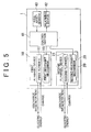
- FIG. 5 is a block diagram that shows the electrical configuration of the vehicle overturn prevention device according to the first embodiment of the present invention.
- the vehicle overturn prevention device 1 includes a control section 41 that includes a microcomputer.
- the first restraint mechanism 19, the second restraint mechanism 29, and an alarming device 42 are connected to the control section 41 so as to be controlled.
- the alarming device 42 issues an alarm to a driver of the combination vehicle 2, and disposed in a driver's cabin of the tractor 3 (see FIG. 1 ), for example.
- Examples of the alarming device 42 include a display monitor and a speaker.
- the control section 41 receives a detection output from a roll angle sensor (roll state detection means) 43 that detects the roll angle of the combination vehicle 2.
- the control section 41 can obtain not only the magnitude of the roll angle of the combination vehicle 2 but also the direction of roll motion of the combination vehicle 2 on the basis of the detection output of the roll angle sensor 43.
- the roll angle sensor 43 is disposed in the trailer 4, for example.
- the roll angle sensor 43 is formed by a gyro sensor, for example.
- FIGs. 6A and 6B illustrate a gyro effect of a general flywheel 100 mounted on a vehicle through a single-gimbal support mechanism.
- FIG. 6A is a schematic diagram that shows a model for illustration of the gyro effect.
- FIG. 6B shows gyro moments that are generated in various directions. As in FIG. 1 , the direction to the front of the combination vehicle 2 is defined as X direction, and the direction to the left of the combination vehicle 2 is defined as Y direction.
- the flywheel 100 is mounted on the combination vehicle 2 with a gimbal shaft 101 extending along the X direction (the direction that coincides with the front-back direction of the combination vehicle 2).
- Automotive vehicles such as the combination vehicle 2 have a large yaw angle speed compared to other types of vehicles such as rail vehicles and water vehicles.
- the yaw angle and the roll angle of the combination vehicle 2 serve as disturbances, and the gyro effect due to such disturbances affects motion of the combination vehicle 2 as indicated by the following formulas (2) and (3).
- the symbols that are used in the formulas (1) to (3) are described in Table 1.
- the roll angle speed (see Table 2) and the yaw angle speed (see Table 2) of the combination vehicle 2 generate a gyro moment on a gimbal 103 of the flywheel 100 about an axis that extends in the X direction (the gyro moment is obtained by subtracting the second term on the right side of the formula (1) from the first term on the right side of the formula (1); also see Table 2).
- the gyro moment generated on the gimbal 103 generates an angular speed on the gimbal 103 (gimbal angle speed shown in Table 2) to generate a gyro moment about an axis that extends in the roll direction of the combination vehicle 2, that is, the X direction (for the gyro moment, see the first term on the right side of the formula (3); also see Table 2).
- the gyro moment can be utilised to prevent an overturn of the combination vehicle 2. If the flywheel 100 is mounted on the combination vehicle 2 through a single-gimbal support mechanism as shown in FIG. 6 , however, the gyro effect of the flywheel 100 may affect motion of the combination vehicle 2 even in the case where the combination vehicle 2 is travelling normally with no abnormality occurring in roll motion of the combination vehicle 2.
- FIGs. 7A to 7C show a mechanism that prevents an overturn of the combination vehicle 2 adopted in the vehicle overturn prevention device 1.
- the flywheel device 10, 20 of the vehicle overturn prevention device 1 adopts a so-called double-gimbal support mechanism in which a flywheel is rotatably supported by two gimbal shafts 15, 17, 25, 27 as discussed earlier.
- the flywheel 11, 21 is rotatably supported by two gimbal shafts 15, 17, 25, 27 (hence the name "double-gimbal support mechanism").
- the flywheel 11, 21 is free in three axial directions with respect to the combination vehicle 2. This allows motion of the combination vehicle 2 and the gyro effect of the flywheel 11, 21 to be dissociated from each other during normal travel of the combination vehicle 2.
- the effect of overturn prevention according to this technique depends on the direction of the yaw angle speed of the combination vehicle 2, that is, the turning direction of the combination vehicle 2.
- the rotational direction of the flywheel 11, 21 determines whether the generated gyro moment acts as a stabiliser against roll motion of the combination vehicle 2 or acts to adversely affect the roll motion.
- a gyro moment in a roll direction that is anticlockwise (in this case, Y direction) toward the front (X direction) is generated on the combination vehicle 2.
- the gyro moment can act as a stabiliser against roll motion of the combination vehicle 2 that is clockwise (opposite to the Y direction) toward the front (X direction).
- the combination vehicle 2 makes roll motion that is clockwise (opposite to the Y direction) toward the front (X direction) mainly when the combination vehicle 2 makes a left turn.
- a numerical simulation was made to verify the effectiveness of overturn prevention through a gyro effect of a flywheel mounted on a vehicle.
- a general-purpose multibody dynamics programme ADAMS was used.
- a full-scale model of a trailer for marine containers (with a maximum payload of 24000 kg) was used.
- the combination vehicle used as the model included a tractor (7000 kg), a trailer (3500 kg), and one flywheel, and was constructed using 28 rigid bodies.
- a container with a length of 40 feet (ft) and a weight of 24000 kg was assumed as the container to be mounted on the trailer.
- FIG. 8 shows the coordinate axes of the combination vehicle that includes the tractor and the trailer. As shown in FIG. 8 , the coordinates are defined with reference to the coupler. In this case, the centre of gravity of the container is positioned at an X coordinate of -5.9 m and a Z coordinate of 1.38 m, and the centre of gravity of the flywheel is positioned at an X coordinate of -6.0 m and a Z coordinate of 0.68 m.
- a numerical simulation was performed under travel conditions with the vehicle model travelling straight ahead at a constant vehicle speed of 110 km/h and with the front wheels of the tractor steered to an actual steering angle of 4 degrees with respect to the straight-ahead direction for a period of time from 10 to 11 seconds to verify the effectiveness of overturn prevention through the gyro effect of the flywheel mounted on the vehicle.
- travel conditions which were determined with reference to instances in which a combination vehicle was overturned, the combination vehicle travelled at a speed that is higher than the legal speed limit in Japan (80 km/h) for lorries that travel on an express way known as motorway or freeway etc., and the vehicle model would be overturned under no control.
- FIG. 9 Variations in roll angle of the vehicle model for rotational angular speeds of the flywheel of 0 rpm (that is, under no control) and 15000 rpm are respectively shown in FIG. 9 . It is seen from FIG. 9 that both the roll angle speed and the roll angle diverge at about 15 seconds to cause an overturn under a condition where the flywheel does not have an angular momentum (when the rotational angular speed of the flywheel is 0 rpm), that is, under no control. It is also seen from FIG. 9 that roll motion of the combination vehicle is suppressed by the gyro effect of the flywheel to prevent an overturn under a condition where the flywheel has an angular momentum of about 40000 Nms or more, that is, under control.
- a mock-up vehicle and a flywheel with a scale of 1:8 were manufactured to perform a mock-up experiment that simulates an overturn of a combination vehicle using a bench test device that considers safety and reproducibility.
- Motion of the mock-up vehicle is reproduced such that yaw motion of the vehicle is reproduced through rotation of the bench test device and roll motion and pitch motion, which are generated by lateral acceleration during a turn due to a centrifugal acceleration generated by the rotation of the bench test device, are reproduced on the mock-up vehicle side.
- FIG. 9 which shows the results of the numerical simulation which was made to verify the effectiveness of overturn prevention through a gyro effect
- yaw angle speed of the mock-up vehicle that is, the rotational speed of the bench test device
- a yaw angle speed with a scale of 1:8 was given on the basis of the yaw angle speed calculated for a period from 9 seconds, which was 1 second before the actual steering angle was introduced, to 15.5 seconds, at which the roll angle and the roll angle speed of the combination vehicle would start diverging under no control.
- the rotational speed of the flywheel was set to 0 rpm (that is, under no control), 3000 rpm, and 8000 rpm.
- FIG. 10 shows variations in roll angle of the mock-up vehicle.
- FIG. 11 is a flowchart that shows the flow of an abnormal roll motion process that is executed in the case where an abnormality occurs in roll motion of the combination vehicle 2. The process is executed by the control section 41 which is shown in FIG. 5 .
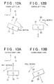
- FIGs. 12A, 12B, 13A, and 13B show variations in attitude of the first and second flywheels 11 and 12 that occur in the case where an abnormality occurs in roll motion of the combination vehicle 2.
- control section 41 monitors whether the value detected by the roll angle sensor 43 falls within an angle threshold range (step S1).
- the control section 41 activates the alarming device 42 to issue a warming to decelerate the combination vehicle 2 (step S2).
- the warning may be a message to be displayed on the display monitor that prompts the driver to perform an operation to decelerate the combination vehicle 2 such as "Slow down” or "Brake".
- the warning may be an audio guidance to be output from the speaker that prompts the driver to perform an operation to decelerate the combination vehicle 2 such as "Slow down” or "Brake".
- control section 41 calculates the direction of the roll motion of the combination vehicle 2 on the basis of the detection output of the roll angle sensor 43. Specifically, the control section 41 detects whether the combination vehicle 2 is turning left. For example, when the combination vehicle 2 which is travelling makes a left turn (YES in step S3), the combination vehicle 2 makes roll motion that is anticlockwise (Y direction) toward the front (X direction) (see FIGs. 12A and 12B ) so that the roll angle detected by the roll angle sensor 43 takes a positive value. When the combination vehicle 2 which is travelling turns right (NO in step S3), meanwhile, the combination vehicle 2 makes roll motion that is clockwise (opposite to the Y direction) toward the front (X direction) (see FIGs. 13A and 13B ) so that the roll angle detected by the roll angle sensor 43 takes a negative value.
- the control section 41 controls the first restraint mechanism 19 of the first flywheel device 10 so as to restrain the second gimbal shaft 17 (step S4). At this time, the control section 41 does not drive the second restraint mechanism 29, and therefore the fourth gimbal shaft 27 is in a released state (step S4).
- the second gimbal shaft 17 remains restrained until predetermined termination conditions are established (YES in step S5; until the roll angle of the combination vehicle 2 becomes equal to or less than a predetermined value, for example).
- a gyro moment in an anticlockwise roll direction (Y direction) toward the front (X direction) is generated on the first flywheel 11 so that the gyro moment acts as a stabiliser against roll motion of the combination vehicle 2 that is clockwise (opposite to the Y direction) toward the front (X direction). This prevents an overturn of the combination vehicle 2 during a left turn.
- the second flywheel 21 is rotatably supported by two gimbal shafts 25 and 27. Therefore, the second flywheel 21 is free in three axial directions with respect to the combination vehicle 2, and in a vertical attitude (with the yaw axis coinciding with the vertical direction). Therefore, no gyro effect is generated on the second flywheel 21.
- control section 41 controls the first restraint mechanism 19 so as to release the second gimbal shaft 17 (step S6). Thereafter, the process is returned.
- step S7 when the combination vehicle 2 which is travelling turns right, that is, when the detected roll angle has a negative value (NO in step S3), the control section 41 controls the second restraint mechanism 29 of the second flywheel device 20 so as to restrain the fourth gimbal shaft 27 (step S7). At this time, the control section 41 does not drive the first restraint mechanism 19, and therefore the second gimbal shaft 17 is in a released state (step S7).
- the fourth gimbal shaft 27 remains restrained until predetermined termination conditions are established (YES in step S8; until the roll angle of the combination vehicle 2 becomes equal to or less than a predetermined value, for example).
- the first flywheel 11 is rotatably supported by two gimbal shafts 15 and 17. Therefore, the first flywheel 11 is free in three axial directions with respect to the combination vehicle 2, and in a vertical attitude (with the yaw axis coinciding with the vertical direction). Therefore, no gyro effect is generated on the first flywheel 11.
- a gyro moment in a clockwise roll direction (opposite to the Y direction) toward the front (X direction) is generated on the second flywheel 11 so that the gyro moment acts as a stabiliser against roll motion of the combination vehicle 2 that is anticlockwise (Y direction) toward the front (X direction). This prevents an overturn of the combination vehicle 2 during a right turn.
- control section 41 controls the second restraint mechanism 29 so as to release the fourth gimbal shaft 27 (step S6). Thereafter, the process is returned.
- the first and second flywheels 11 and 21 rotate in opposite directions to each other.
- the direction of the gyro moment that is generated on the combination vehicle 2 by the first and second flywheels 11 and 21 depends on the rotational direction of the flywheels 11 and 12.
- the direction of the gyro moment that is generated on the combination vehicle 2 by the first flywheel 11 and the direction of the gyro moment that is generated on the combination vehicle 2 by the second flywheel 21 can be made different from each other.
- the flywheel that generates a gyro effect can be switched between the first and second flywheels 11 and 21 in accordance with the direction of roll motion of the combination vehicle 2.
- the gyro effect of either of the flywheels 11 and 21 can be caused to act as a stabiliser against roll motion of the combination vehicle 2 to prevent an overturn of the combination vehicle 2, irrespective of whether the combination vehicle 2 is turning left or right.
- FIG. 14 is a block diagram that shows the electrical configuration of a vehicle overturn prevention device 50 according to a second embodiment of the present invention.
- elements that correspond to those in the first embodiment which is shown in FIGs. 1 to 5 and 7 to 13 are denoted by the same reference numerals as those of the first embodiment which is shown in FIGs. 1 to 5 and 7 to 13 to omit redundant description.
- the vehicle overturn prevention device 50 is different from the counterpart in the first embodiment which is shown in FIGs. 1 to 5 and 7 to 13 in being capable of transmitting a deceleration command signal (deceleration control signal) to a vehicle deceleration section 51 of the tractor 3 and in that the alarming device 42 (see FIG. 5 ) has been removed.
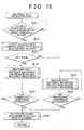
- FIG. 15 is a flowchart that shows the flow of an abnormal roll motion process that is executed by the vehicle overturn prevention device 50 in the case where an abnormality occurs in roll motion of the combination vehicle 2. The process is executed by the control section 41 which is shown in FIG. 5 .
- control section 41 monitors whether the value detected by the roll angle sensor 43 falls within an angle threshold range (step S11).
- the control section 41 transmits a deceleration command signal for deceleration to the vehicle deceleration section 51 (step S12).
- the vehicle deceleration section 51 is a mechanism that decelerates the combination vehicle 2, and may be, for example, a mechanism that accelerates the flywheels 11 and 21, a brake mechanism (foot brake mechanism) for the tractor 3, a mechanism that applies engine braking for the tractor 3 (for example, a transmission), or the like.
- the vehicle deceleration section 51 is driven to reduce the vehicle speed on the basis of the transmitted deceleration command signal to decelerate the combination vehicle 2.
- the control section 41 can control the flywheel 11, 21 so as to decelerate the combination vehicle 2.
- the rotational speed of the flywheel 11, 21 which is rotating is further raised to increase the gyro moment generated on the flywheel 11, 21.
- control section 41 calculates the direction of the roll motion of the combination vehicle 2 on the basis of the detection output of the roll angle sensor 43. Specifically, the control section 41 detects whether the combination vehicle 2 is turning left. When the combination vehicle 2 which is travelling turns left, that is, when the detected roll angle has a positive value (YES in step S13), the control section 41 controls the first restraint mechanism 19 of the first flywheel device 10 so as to restrain the second gimbal shaft 17 (step S14). At this time, the control section 41 does not drive the second restraint mechanism 29, and therefore the fourth gimbal shaft 27 is in a released state (step S14).
- the second gimbal shaft 17 remains restrained until predetermined termination conditions are established (YES in step S15; until the roll angle of the combination vehicle 2 becomes equal to or less than a predetermined value, for example).
- the control section 41 controls the first restraint mechanism 19 so as to release the second gimbal shaft 17 (step S16). Thereafter, the process is returned.
- the control section 41 controls the second restraint mechanism 29 of the second flywheel device 20 so as to restrain the fourth gimbal shaft 27 (step S17). At this time, the control section 41 does not drive the first restraint mechanism 19, and therefore the second gimbal shaft 17 is in a released state.
- the fourth gimbal shaft 27 remains restrained until predetermined termination conditions are established (YES in step S18; until the roll angle of the combination vehicle 2 becomes equal to or less than a predetermined value, for example). After the predetermined termination conditions are established, the control section 41 controls the second restraint mechanism 29 so as to release the fourth gimbal shaft 27 (step S16). Thereafter, the process is returned.
- steps S11, S13, S14, S15, S16, S17, and S18 are the same as the processes in steps S1, S3, S4, S5, S6, S7, and S8 in FIG. 11 .
- FIG. 16 is a block diagram that shows the electrical configuration of a vehicle overturn prevention device 60 according to a third embodiment of the present invention.
- elements that correspond to those in the first embodiment which is shown in FIGs. 1 to 5 and 7 to 13 are denoted by the same reference numerals as those of the embodiment which is shown in FIGs. 1 to 5 and 7 to 13 to omit redundant description.
- the vehicle overturn prevention device 60 is different from the counterpart in the first embodiment which is shown in FIGs. 1 to 5 and 7 to 13 in that the first flywheel device 10 is provided with a first rotational angle sensor (roll state detection means) 61 (which is indicated by a double dotted line in FIG.
- the second flywheel device 20 is provided with a second rotational angle sensor (roll state detection means) 62 (which is indicated by a double dotted line in FIG. 2 ) associated with the third gimbal shaft 25 to detect the angle of rotation of the third gimbal 26 in the roll direction.
- the roll angle sensor 43 has been removed. Detection outputs of the first and second rotational angle sensors 61 and 62 are input to the control section 41.
- a resolver for example, is adopted as the first and second rotational angle sensors 61 and 62.
- one of the first and second flywheels 11 and 21 is rotatably supported by both the first gimbal shaft 15 and the second gimbal shaft 17, and the other of the first and second flywheels 11 and 21 is restricted from rotating about the gimbal shaft 17, 27 which is orthogonal to the front-back direction of the combination vehicle 2.
- one of the first and second flywheels 11, 21 is free in three axial directions with respect to the combination vehicle 2.
- the rotational angle sensor 61, 62 which is provided in association with the flywheel 11, 21 is caused to function as a gyro sensor so that the roll angle of the combination vehicle 2 can be detected with no roll angle sensor 43.
- the combination vehicle 2 makes roll motion that is anticlockwise (Y direction) toward the front (X direction) (see FIGs. 12A and 12B ).
- the second flywheel 21 is rotatably supported by both the third gimbal shaft 25 and the fourth gimbal shaft 27, and the first flywheel 11 is restricted from rotating about the second gimbal shaft 17 which is orthogonal to the front-back direction of the combination vehicle 2.
- the control section 41 references the detection output of the second rotational angle sensor 62 to calculate the roll angle of the combination vehicle 2 on the basis of the detection output.
- the combination vehicle 2 makes roll motion that is clockwise (opposite to the Y direction) toward the front (X direction) (see FIGs. 13A and 13B ).
- the first flywheel 11 is rotatably supported by both the first gimbal shaft 15 and the second gimbal shaft 17, and the second flywheel 21 is restricted from rotating about the first gimbal shaft 15 which is orthogonal to the front-back direction of the combination vehicle 2.
- the control section 41 references the detection output of the first rotational angle sensor 61 to calculate the roll angle of the combination vehicle 2 on the basis of the detection output.
- the first embodiment and the second embodiment may be combined with each other. That is, the control section 41 may be adapted to drive the alarming device 42 to issue a warming to decelerate the combination vehicle 2 and to transmit a deceleration command signal for deceleration to the vehicle deceleration section 51 if an abnormality occurs in roll motion of the combination vehicle 2 so that the detected roll angle exceeds an angle threshold.
- the flywheel devices 10 and 20 may be used to perform control (pitch control) for suppressing a pitch phenomenon of the combination vehicle 2.
- pitch control control
- a pitch phenomenon in which the front portion of the combination vehicle 2 is lowered and the rear portion of the combination vehicle 2 is raised may be caused.
- the combination vehicle 2 is often abruptly decelerated when the combination vehicle 2 makes a turn. In this case, it is necessary to suppress occurrence of a pitch phenomenon in the combination vehicle 2, in addition to preventing an overturn of the combination vehicle 2, when the combination vehicle 2 makes a turn.
- a third restraint mechanism (not shown) that is associated with the first gimbal shaft 15 to restrain the first gimbal shaft 15 to restrict rotation of the first flywheel 11 about the first gimbal shaft 15 may be provided, and a fourth restraint mechanism (not shown) that is associated with the third gimbal shaft 25 to restrain the third gimbal shaft 25 to restrict rotation of the second flywheel 21 about the third gimbal shaft 25 may be provided, so that the third and fourth restraint mechanisms (not shown) are subjected to control (pitch control) (so as to be restrained/released) to suppress occurrence of a pitch phenomenon of the combination vehicle 2.
- control pitch control
- a roll angle speed detection sensor that detects a roll angle speed may be adopted, besides the roll angle sensor 43, as the roll state detection means.
- the roll state (that is, the risk of an overturn) of the combination vehicle 2 may be detected using detection outputs of a vehicle speed sensor and a steering angle sensor or using detection outputs of a vehicle speed sensor and a lateral acceleration sensor.
- the amount of energy that is stored in the first flywheel 11 which functions as the left-turn flywheel may be set to be larger than the amount of energy that is stored in the second flywheel 21 which functions as the right-turn flywheel.
- the diameter of the first wheel body may be made larger than that of the second wheel body, rather than the first and second wheel bodies have the same diameter as each other.
- the amount of energy that is stored in the first flywheel 11 can be made larger than the amount of energy that is stored in the second flywheel 21.
- the gyro moment that is generated on the first flywheel 11 is larger than the gyro moment that is generated on the second flywheel 21.
- the radius of an arcuate track of a vehicle during a left turn is smaller than the radius of an arcuate track of the vehicle during a right turn.
- the angular speed for a turn is higher during a left turn than during a right turn. Therefore, a larger force in the roll direction acts on the combination vehicle 2 during a left turn than during a right turn.
- the amount of energy that is stored in the first flywheel 11 By setting the amount of energy that is stored in the first flywheel 11 to be larger than the amount of energy that is stored in the second flywheel 21, it is possible to secure the amount of energy that is stored in the first flywheel 11 which functions as the left-turn flywheel, even in the case where the total amount of energy that is stored in the two flywheels 11 and 21 is insufficient, to allow a gyro moment with a sufficient magnitude to act on the first flywheel 11, and to effectively suppress an overturn when the vehicle makes a left turn in countries where vehicles are driven on the left side of the road.
- the first and second wheel bodies have generally the same diameter as each other, and the first flywheel 11 is rotated at a higher speed than that of the second flywheel 21.
- the two flywheel devices may be arranged along the left-right direction in the combination vehicle 2.
- the combination vehicle 2 makes remarkable roll motion on the left side.
- the flywheel of the flywheel device on the left side may be rotated anticlockwise as view in plan.
- the combination vehicle 2 makes remarkable roll motion on the right side.
- the flywheel of the flywheel device on the right side may be rotated clockwise as view in plan.
- the two flywheel devices may be arranged along the up-down direction in the combination vehicle 2.
- the pair of flywheel devices may be mounted on the tractor 3, rather than on the trailer 4, or may be mounted on the container 6 which is mounted on the trailer 4.
- a full trailer or a pole trailer may be adopted, rather than a semi-trailer, as a towed vehicle.
- the vehicle overturn prevention device 1, 50, 60 may be applied as a vehicle overturn prevention device for lorries and other large-sized vehicles, rather than combination vehicles.
Landscapes
- Engineering & Computer Science (AREA)
- Chemical & Material Sciences (AREA)
- Combustion & Propulsion (AREA)
- Transportation (AREA)
- Mechanical Engineering (AREA)
- Vehicle Cleaning, Maintenance, Repair, Refitting, And Outriggers (AREA)
- Electric Propulsion And Braking For Vehicles (AREA)
- Control Of Driving Devices And Active Controlling Of Vehicle (AREA)
- Hybrid Electric Vehicles (AREA)
Abstract
Description
- The present invention relates to a device for preventing an overturn of a vehicle by suppressing roll motion of a vehicle during turning of a vehicle.
- Vehicle overturn prevention devices that prevent an overturn of a vehicle by suppressing roll motion of the vehicle are known. An example of such vehicle overturn prevention devices includes a flywheel for storing energy that is mounted on a vehicle as a so-called double-gimbal support mechanism (see Japanese Patent Application Publication No.
2008-143390 JP-2008-143390-A JP-2008-143390-A - It is desirable to effectively suppress roll motion of a vehicle using a flywheel-type vehicle overturn prevention device.
- The present invention provides a flywheel-type vehicle overturn preventing device that prevents an overturn of a vehicle by effectively suppressing roll motion of a vehicle during a turn. More specifically, the present invention provides a flywheel-type vehicle overturn prevention device that includes a plurality of (for example, two) flywheels.
- The direction of a gyro moment that is generated on a vehicle by a flywheel depends on the rotational direction of the flywheel. More specifically, if an angle of 90° or greater is provided between the vector of the yaw angle speed of the vehicle and the vector of the angular momentum of the flywheel, the gyro effect of the flywheel acts adversely.
- An aspect of the present invention relates to a vehicle overturn prevention device that is mounted on a vehicle to prevent an overturn of the vehicle. The vehicle overturn prevention device includes: a first flywheel device that includes a first flywheel that is configured as an energy storage device and that rotates in a first rotational direction, and a first gimbal support structure that rotatably supports the first flywheel about a first shaft and a second shaft that extends orthogonally to the first shaft and orthogonally to a front-back direction of the vehicle; and a second flywheel device that includes a second flywheel that is configured as an energy storage device and that rotates in a second rotational direction that is opposite to the first rotational direction, and a second gimbal support structure that rotatably supports the second flywheel about a third shaft and a fourth shaft that extends orthogonally to the third shaft and orthogonally to the front-back direction of the vehicle. The first gimbal support structure includes first rotation restriction means for restricting rotation of the first flywheel about the second shaft. The second gimbal support structure includes second rotation restriction means for restricting rotation of the second flywheel about the fourth shaft. The vehicle overturn prevention device further includes rotation restriction control means for controlling the first rotation restriction means and the second rotation restriction means so as to restrict rotation of the first flywheel without restricting rotation of the second flywheel when the vehicle makes roll motion in one roll direction and so as to restrict rotation of the second flywheel without restricting rotation of the first flywheel when the vehicle makes roll motion in the other roll direction.
- According to the above aspect, in the vehicle, the first flywheel is rotatably supported by both the first and second shafts. In this state, the first flywheel is free in three axial directions with respect to the vehicle, and thus no gyro effect is generated on the first flywheel. Meanwhile, in a state in which rotation of the first flywheel about the second shaft which is orthogonal to the front-back direction of the vehicle is restricted, a gyro effect is generated on the first flywheel during a turn of the vehicle so that the gyro effect can act as a stabiliser against roll motion of the vehicle.
- In the vehicle, in addition, the second flywheel is rotatably supported by both the third and fourth shafts. In this state, the second flywheel is free in three axial directions with respect to the vehicle, and thus no gyro effect is generated on the second flywheel. Meanwhile, in a state in which rotation of the second flywheel about the fourth shaft which is orthogonal to the front-back direction of the vehicle is restricted, a gyro effect is generated on the second flywheel during a turn of the vehicle so that the gyro effect can act as a stabiliser against roll motion of the vehicle.
- The first and second flywheels rotate in opposite directions to each other. Each of the direction of the gyro moment which is generated on the vehicle by the first and second flywheels depends on the rotational direction of the flywheels. Thus, the direction of the gyro moment which is generated on the vehicle by the first flywheel and the direction of the gyro moment which is generated on the vehicle by the second flywheel can be made different from each other.
- When the vehicle makes roll motion in one roll direction, only the rotation of the second shaft of the first flywheel device is restricted, without restricting the rotation of the fourth shaft of the second flywheel device, to generate a gyro effect only on the first flywheel. When the vehicle makes roll motion in the other roll direction, meanwhile, only the rotation of the fourth shaft of the second flywheel device is restricted, without restricting the rotation of the second shaft of the first flywheel device, to generate a gyro effect only on the second flywheel. In other words, the flywheel that generates a gyro effect can be switched between the first and second flywheels in accordance with the direction of roll motion of the vehicle. Thus, according to the above aspect, the gyro effect of either of the flywheels can be caused to act as a stabiliser against roll motion of the vehicle to prevent an overturn of the vehicle, irrespective of whether the vehicle is turning left or turning right.
- In the above aspect, the first flywheel device and the second flywheel device may be arranged in the front-back direction, a left-right direction, or an up-down direction of the vehicle.
- In the above aspect, the vehicle overturn prevention device may further include: roll state detection means for detecting a roll state associated with roll motion of the vehicle; and energy recovery control means for executing energy recovery control in which energy of the vehicle is recovered by the first flywheel and the second flywheel in the case where the roll state which is detected by the roll state detection means exceeds a threshold that is determined in advance.
- According to the above aspect, energy of the vehicle is recovered by the flywheel through the energy recovery control. When the energy is recovered, the rotational speed of the flywheel, which is rotating, is further raised to enhance the gyro effect which is generated on the flywheel. In other words, the gyro moment which is generated on the flywheel can be increased.
- In the above aspect, the vehicle overturn prevention device may further include: alarming means for issuing a predetermined alarm to a driver of the vehicle; and alarm control means for controlling the alarming means so as to issue an alarm that promotes an operation to decelerate the vehicle.
- In the above aspect, the vehicle overturn prevention device may further include vehicle deceleration control signal transmission means for transmitting a control signal for decelerating the vehicle.
- In the above aspect, the vehicle deceleration control signal transmission means may control the energy recovery control means to decelerate the vehicle.
- In the above aspect, an amount of energy that is stored in the first flywheel and an amount of energy that is stored in the second flywheel may be different from each other.
- In this case, the amount of energy that is stored in one of the first and second flywheels on which a gyro effect that acts as a stabiliser on the vehicle which is turning left is generated (hereinafter referred to as "left-turn flywheel") may be larger than the amount of energy that is stored in the flywheel on which a gyro effect that acts as a stabiliser on the vehicle which is turning right (hereinafter referred to as "right-turn flywheel").
- Features, advantages, and technical and industrial significance of exemplary embodiments of the invention will be described below with reference to the accompanying drawings, in which like numerals denote like elements, and wherein:
-
FIG. 1 is an exploded perspective view that shows a schematic configuration of a combination vehicle that incorporates a vehicle overturn prevention device according to a first embodiment of the present invention; -
FIG. 2 shows a schematic configuration of first and second flywheel devices; -
FIGs. 3A and 3B are each a cross-sectional view that shows a schematic configuration of an example of first and/or second restraint mechanisms; -
FIG. 4 is a cross-sectional view that shows a schematic configuration of another example of the first and/or second restraint mechanisms; -
FIG. 5 is a block diagram that shows the electrical configuration of the vehicle overturn prevention device according to the first embodiment of the present invention; -
FIGs. 6A and 6B illustrate a gyro effect of a general flywheel mounted on a vehicle through a single-gimbal support mechanism; -
FIGs. 7A to 7C show a mechanism that prevents an overturn of a combination vehicle using the vehicle overturn prevention device according to the first embodiment of the present invention; -
FIG. 8 shows coordinate axes of the combination vehicle; -
FIG. 9 is a graph that shows variations in roll angle of a vehicle model; -
FIG. 10 is a graph that shows variations in roll angle of a mock-up vehicle; -
FIG. 11 is a flowchart that shows the flow of an abnormal roll motion process that is executed in the case where an abnormality occurs in roll motion of the combination vehicle; -
FIGs. 12A and 12B show variations in attitude of first and second flywheels that occur in the case where an abnormality occurs in roll motion when the combination vehicle makes a left turn; -
FIGs. 13A and 13B show variations in attitude of the first and second flywheels that occur in the case where an abnormality occurs in roll motion when the combination vehicle makes a right turn; -
FIG. 14 is a block diagram that shows the electrical configuration of a vehicle overturn prevention device according to a second embodiment of the present invention; -
FIG. 15 is a flowchart that shows the flow of an abnormal roll motion process that is executed in the case where an abnormality occurs in roll motion of a combination vehicle; and -
FIG. 16 is a block diagram that shows the electrical configuration of a vehicle overturn prevention device according to a third embodiment of the present invention. - Embodiments of the present invention will be described below with reference to the accompanying drawings.
FIG. 1 is an exploded perspective view that shows a schematic configuration of acombination vehicle 2 that serves as an example of an automotive vehicle that incorporates a vehicle overturnprevention device 1 according to a first embodiment of the present invention. Thecombination vehicle 2 is a semi-trailer-type combination vehicle, for example, and includes atractor 3 that serves as a towing vehicle, and a semi-trailer (hereinafter simply referred to as "trailer") 4 that serves as a towed vehicle. Thetractor 3 and thetrailer 4 are coupled to each other by a coupler (not shown) that serves as a coupling that can make rotational motion about a vertical axis. Thetrailer 4 is configured such that acontainer 6 can be mounted on the upper surface of thetrailer 4. In the following description, the direction to the front of thecombination vehicle 2 is defined as X direction, the direction to the left of thecombination vehicle 2 is defined as Y direction, and the direction to vertically above thecombination vehicle 2 is defined as Z direction. - First and
second flywheel devices combination vehicle 2 to be arranged side by side in the front-back direction of thecombination vehicle 2. More particularly, thefirst flywheel device 10 is disposed in the front portion of thetrailer 4, and thesecond flywheel device 20 is disposed in the rear portion of thetrailer 4. Thetrailer 4 includes afront frame 7 that extends in the left-right direction, arear frame 8 that extends in the left-right direction, and a plurality of (for example, two) connectingframes 9 that connect thefront frame 7 and therear frame 8 to each other. The left and right connectingframes 9 extend in the front-back direction to connect the left and right ends of thefront frame 7 and the left and right ends of therear frame 8 to each other. The first andsecond flywheel devices FIG. 1 , the first andsecond flywheel devices container 6 from the viewpoint of viewability of the drawing. However, theflywheel devices trailer 4. In addition, thetrailer 4 is also provided with an energy supply device (not shown) that supplies energy to or allows energy to be recovered by the first andsecond flywheel devices frame 9. Thus, with the first andsecond flywheel devices combination vehicle 2, a sufficient space for arrangement of peripheral devices such as the energy supply device can be secured also in the width direction of thetrailer 4. - The
first flywheel device 10 includes afirst flywheel 11 for storing energy. Thesecond flywheel device 20 includes asecond flywheel 21 for storing energy. An energy supply device is connected to the first andsecond flywheels second flywheels second flywheels 11-69511 JP-A-11-69511 -
FIG. 2 shows a schematic configuration of thefirst flywheel device 10. The configuration of thefirst flywheel device 10 will be described with reference toFIGs. 1 and2 . Thefirst flywheel 11 includes a disc-like first wheel body (not shown) and afirst housing 13 that houses the first wheel body. The first wheel body is formed using cast iron or CFRP (Carbon Fiber Reinforced Plastics). The first wheel body rotates about a firstrotary shaft 14 with respect to thefirst housing 13 at a high speed anticlockwise as viewed in plan. In other words, the direction of the angular speed of the first wheel body is from bottom up. Energy is stored into thefirst flywheel 11 using the energy of the rotation of the first wheel body. Rotation of the first wheel body is hereinafter occasionally referred to as rotation offirst flywheel 11. - The
first flywheel 11 is supported by afirst gimbal 16, which serves as an inner gimbal, so as to be rotatable about the firstrotary shaft 14. Thefirst gimbal 16 is rotatably supported by asecond gimbal 18, which serves as an outer gimbal, via a first gimbal shaft (first shaft) 15. Thesecond gimbal 18 is supported by a housing (not shown) of thefirst flywheel device 10 via a second gimbal shaft (second shaft) 17. Thesecond gimbal shaft 17 extends along the Y direction (to be included in a plane that is orthogonal to the X direction). Thefirst gimbal shaft 15 extends to be included in a plane (X-Z plane) that is orthogonal to the Y direction. The imaginary intersection point between thefirst gimbal shaft 15 and thesecond gimbal shaft 17 coincides with the centre of gravity of the first flywheel 11 (first wheel body). Therefore, with no external force acting on thecombination vehicle 2, thefirst flywheel 11 can be kept in a predetermined attitude (with the firstrotary shaft 14 extending along the vertical direction). - The
second flywheel device 20 is configured in the same way as thefirst flywheel device 10. The configuration of thesecond flywheel device 20 will be described with reference toFIGs. 1 and2 . Thesecond flywheel 21 includes a disc-like second wheel body (not shown) and asecond housing 23 that houses the second wheel body. The second wheel body rotates about a secondrotary shaft 24 with respect to thesecond housing 23 at a high speed clockwise as viewed in plan (in the direction opposite to the rotational direction of the first flywheel 11). In other words, the direction of the angular speed of the second wheel body is from top down. Energy is stored into thesecond flywheel 21 using the kinetic energy of the rotation of the second wheel body. Rotation of the second wheel body is hereinafter occasionally referred to as rotation ofsecond flywheel 21. - In the embodiment, the first wheel body and the second wheel body have the same diameter and the same mass as each other, for example. However, the present invention is not limited thereto. The
second flywheel 21 is supported by athird gimbal 26, which serves as an inner gimbal, so as to be rotatable about the secondrotary shaft 24. Thethird gimbal 26 is rotatably supported by afourth gimbal 28, which serves as an outer gimbal, via a third gimbal shaft (third shaft) 25. Thefourth gimbal 28 is supported by a housing (not shown) of thesecond flywheel device 20 via a fourth gimbal shaft (fourth shaft) 27. Thefourth gimbal shaft 27 extends along the Y direction (to be included in a plane that is orthogonal to the X direction). Thethird gimbal shaft 25 extends to be included in a plane (X-Z plane) that is orthogonal to the Y direction. The imaginary intersection point between thethird gimbal shaft 25 and thefourth gimbal shaft 27 coincides with the centre of gravity of the second flywheel 21 (second wheel body). Therefore, with no external force acting on thecombination vehicle 2, thesecond flywheel 21 can be kept in a predetermined attitude (with the secondrotary shaft 24 extending along the vertical direction). - In the first and
second flywheel devices third gimbals fourth gimbals third gimbal shafts fourth gimbal shafts - The
first flywheel device 10 includes a first restraint mechanism (first rotation restriction means) 19 (seeFIGs. 3A, 3B, and 4 ) that restrains thesecond gimbal shaft 17 to restrict rotation of thefirst flywheel 11 about thesecond gimbal shaft 17. Thesecond flywheel device 20 includes a second restraint mechanism (second rotation restriction means) 29 (seeFIGs. 3A, 3B, and 4 ) that restrains thefourth gimbal shaft 27 to restrict rotation of thesecond flywheel 21 about thefourth gimbal shaft 27. Examples of the first and/orsecond restraint mechanism FIGs. 3A, 3B, and FIG. 4 . -
FIGs. 3A and 3B show a schematic configuration in which afriction brake 30 is adopted as an example of the first and/orsecond restraint mechanisms FIG. 3A is a cross-sectional view that shows an essential portion of thefriction brake 30.FIG. 3B shows thefriction brake 30 as seen along the arrow III ofFIG. 3A . Thefriction brake 30 includesbrake pads 32 disposed on abearing 31 of the second and/orfourth gimbal shafts pistons 33 that push thebrake pads 32 against the outer peripheral surface of the second and/orfourth gimbal shafts pistons 33 can push thebrake pads 32 against the outer peripheral surface of the second and/orfourth gimbal shafts fourth gimbal shafts gimbal shafts -
FIG. 4 shows a schematic configuration in which anelectromagnetic brake 35 is adopted as another example of the first and/orsecond restraint mechanisms electromagnetic brake 35, agenerator 36 generates a voltage (induced electromotive force), and the induced electromotive force is consumed as thermal energy by the resistance of aresistor 37 to act as a brake. -
FIG. 5 is a block diagram that shows the electrical configuration of the vehicle overturn prevention device according to the first embodiment of the present invention. The vehicle overturnprevention device 1 includes acontrol section 41 that includes a microcomputer. Thefirst restraint mechanism 19, thesecond restraint mechanism 29, and analarming device 42 are connected to thecontrol section 41 so as to be controlled. Thealarming device 42 issues an alarm to a driver of thecombination vehicle 2, and disposed in a driver's cabin of the tractor 3 (seeFIG. 1 ), for example. Examples of thealarming device 42 include a display monitor and a speaker. Thecontrol section 41 receives a detection output from a roll angle sensor (roll state detection means) 43 that detects the roll angle of thecombination vehicle 2. Thecontrol section 41 can obtain not only the magnitude of the roll angle of thecombination vehicle 2 but also the direction of roll motion of thecombination vehicle 2 on the basis of the detection output of theroll angle sensor 43. Theroll angle sensor 43 is disposed in thetrailer 4, for example. Theroll angle sensor 43 is formed by a gyro sensor, for example. -
FIGs. 6A and 6B illustrate a gyro effect of ageneral flywheel 100 mounted on a vehicle through a single-gimbal support mechanism.FIG. 6A is a schematic diagram that shows a model for illustration of the gyro effect.FIG. 6B shows gyro moments that are generated in various directions. As inFIG. 1 , the direction to the front of thecombination vehicle 2 is defined as X direction, and the direction to the left of thecombination vehicle 2 is defined as Y direction. - The
flywheel 100 is mounted on thecombination vehicle 2 with agimbal shaft 101 extending along the X direction (the direction that coincides with the front-back direction of the combination vehicle 2). Automotive vehicles such as thecombination vehicle 2 have a large yaw angle speed compared to other types of vehicles such as rail vehicles and water vehicles. In the case where theflywheel 100 is mounted on thecombination vehicle 2 through a single-gimbal support mechanism, the yaw angle and the roll angle of thecombination vehicle 2 serve as disturbances, and the gyro effect due to such disturbances affects motion of thecombination vehicle 2 as indicated by the following formulas (2) and (3). The symbols that are used in the formulas (1) to (3) are described in Table 1.


[Table 1] ω Angular speed of flywheel θ Rotational angle of gimbal shaft φ Roll angle of vehicle λ Yaw angle of vehicle Jy Moment of inertia about pitch axis of flywheel Jy Moment of inertia about yaw axis of flywheel Ix Moment of inertia about roll axis of vehicle Iz Moment of inertia about yaw axis of vehicle H Angular momentum of flywheel Cx Attenuation coefficient of roll axis of vehicle Cz Attenuation coefficient of yaw axis of vehicle C Attenuation coefficient of gimbal shaft Kx Spring coefficient of roll axis of vehicle Kz Spring coefficient of yaw axis of vehicle k Spring constant of gimbal shaft Tx Disturbance torque about roll axis of vehicle Tz Disturbance torque about yaw axis of vehicle M Torque applied to gimbal shaft - When the formulas (1) to (3) and Table 1 are summarised in a matrix, the following formula (4) is obtained:

- The terms for the gyro moments on the right side of the formulas (1) to (3) are shown in Table 2:
[Table 2] Angular momentum H Disturbance angular speed Ω Gyro moment H×Ω |H×Ω| Manner of action Formula (1) First term on right side Jz(ω) Roll angle speed φ Jzωφcosθ +Y direction of gimbal shaft Second term on right side Yaw angle speed λ Jzωλsinθ -Y direction of gimbal shaft Formula (2) First term on right side Gimbal angle speed θ Jzωθcosθ -X direction of vehicle Formula (3) First term on right side Jzωθsinθ +Z direction of vehicle - The roll angle speed (see Table 2) and the yaw angle speed (see Table 2) of the
combination vehicle 2 generate a gyro moment on agimbal 103 of theflywheel 100 about an axis that extends in the X direction (the gyro moment is obtained by subtracting the second term on the right side of the formula (1) from the first term on the right side of the formula (1); also see Table 2). The gyro moment generated on thegimbal 103 generates an angular speed on the gimbal 103 (gimbal angle speed shown in Table 2) to generate a gyro moment about an axis that extends in the roll direction of thecombination vehicle 2, that is, the X direction (for the gyro moment, see the first term on the right side of the formula (3); also see Table 2). The gyro moment can be utilised to prevent an overturn of thecombination vehicle 2. If theflywheel 100 is mounted on thecombination vehicle 2 through a single-gimbal support mechanism as shown inFIG. 6 , however, the gyro effect of theflywheel 100 may affect motion of thecombination vehicle 2 even in the case where thecombination vehicle 2 is travelling normally with no abnormality occurring in roll motion of thecombination vehicle 2. -
FIGs. 7A to 7C show a mechanism that prevents an overturn of thecombination vehicle 2 adopted in the vehicle overturnprevention device 1. In contrast to the general single-gimbal support mechanism which is shown inFIGs. 6A and 6B , theflywheel device prevention device 1 adopts a so-called double-gimbal support mechanism in which a flywheel is rotatably supported by twogimbal shafts combination vehicle 2 is travelling normally (seeFIG. 7A ), theflywheel gimbal shafts flywheel combination vehicle 2. This allows motion of thecombination vehicle 2 and the gyro effect of theflywheel combination vehicle 2. - When an abnormality occurs in roll motion of the combination vehicle 2 (see
FIG. 7B ), thegimbal shaft combination vehicle 2 is restrained. Therefore, theflywheel 11, 12 is rotatable only about thegimbal shaft FIG. 7C ). In this case, a gyro effect is generated on theflywheel combination vehicle 2 and the gyro effect of theflywheel flywheel combination vehicle 2. - As is seen also from the formula (4), the effect of overturn prevention according to this technique depends on the direction of the yaw angle speed of the
combination vehicle 2, that is, the turning direction of thecombination vehicle 2. In other words, the rotational direction of theflywheel combination vehicle 2 or acts to adversely affect the roll motion. - That is, when the direction of the angular speed of the
flywheel flywheel combination vehicle 2. The gyro moment can act as a stabiliser against roll motion of thecombination vehicle 2 that is clockwise (opposite to the Y direction) toward the front (X direction). Thecombination vehicle 2 makes roll motion that is clockwise (opposite to the Y direction) toward the front (X direction) mainly when thecombination vehicle 2 makes a left turn. Thus, it is possible to prevent an overturn of thecombination vehicle 2 during a left turn utilising a gyro moment generated on thecombination vehicle 2 when the direction of the angular speed of theflywheel - When the direction of the angular speed of the
flywheel combination vehicle 2. The gyro moment can act as a stabiliser against roll motion of thecombination vehicle 2 that is anticlockwise (Y direction) toward the front (X direction). Thecombination vehicle 2 makes roll motion that is anticlockwise (Y direction) toward the front (X direction) mainly when thecombination vehicle 2 makes a right turn. Thus, it is possible to prevent an overturn of thecombination vehicle 2 during a right turn utilising a gyro moment generated on thecombination vehicle 2 when the direction of the angular speed of theflywheel - Other details of the mechanism for overturn prevention through the
flywheel JP-2008-143390-A - A numerical simulation was made to verify the effectiveness of overturn prevention through a gyro effect of a flywheel mounted on a vehicle. In the numerical simulation, a general-purpose multibody dynamics programme ADAMS was used. A full-scale model of a trailer for marine containers (with a maximum payload of 24000 kg) was used. The combination vehicle used as the model included a tractor (7000 kg), a trailer (3500 kg), and one flywheel, and was constructed using 28 rigid bodies. A container with a length of 40 feet (ft) and a weight of 24000 kg was assumed as the container to be mounted on the trailer.
-
FIG. 8 shows the coordinate axes of the combination vehicle that includes the tractor and the trailer. As shown inFIG. 8 , the coordinates are defined with reference to the coupler. In this case, the centre of gravity of the container is positioned at an X coordinate of -5.9 m and a Z coordinate of 1.38 m, and the centre of gravity of the flywheel is positioned at an X coordinate of -6.0 m and a Z coordinate of 0.68 m. - A numerical simulation was performed under travel conditions with the vehicle model travelling straight ahead at a constant vehicle speed of 110 km/h and with the front wheels of the tractor steered to an actual steering angle of 4 degrees with respect to the straight-ahead direction for a period of time from 10 to 11 seconds to verify the effectiveness of overturn prevention through the gyro effect of the flywheel mounted on the vehicle. Under such travel conditions, which were determined with reference to instances in which a combination vehicle was overturned, the combination vehicle travelled at a speed that is higher than the legal speed limit in Japan (80 km/h) for lorries that travel on an express way known as motorway or freeway etc., and the vehicle model would be overturned under no control. The moment of inertia of the flywheel was I = diag (25.7, 17.1, 17.1) (in units of kgm2), the rotational angular speed was varied among 0 rpm (that is, under no control), 10000 rpm, 13000 rpm, 15000 rpm, and 18000 rpm.
- Variations in roll angle of the vehicle model for rotational angular speeds of the flywheel of 0 rpm (that is, under no control) and 15000 rpm are respectively shown in
FIG. 9 . It is seen fromFIG. 9 that both the roll angle speed and the roll angle diverge at about 15 seconds to cause an overturn under a condition where the flywheel does not have an angular momentum (when the rotational angular speed of the flywheel is 0 rpm), that is, under no control. It is also seen fromFIG. 9 that roll motion of the combination vehicle is suppressed by the gyro effect of the flywheel to prevent an overturn under a condition where the flywheel has an angular momentum of about 40000 Nms or more, that is, under control. - In the mock-up experiment, a mock-up vehicle and a flywheel with a scale of 1:8 were manufactured to perform a mock-up experiment that simulates an overturn of a combination vehicle using a bench test device that considers safety and reproducibility. Motion of the mock-up vehicle is reproduced such that yaw motion of the vehicle is reproduced through rotation of the bench test device and roll motion and pitch motion, which are generated by lateral acceleration during a turn due to a centrifugal acceleration generated by the rotation of the bench test device, are reproduced on the mock-up vehicle side.
-
FIG. 9 which shows the results of the numerical simulation which was made to verify the effectiveness of overturn prevention through a gyro effect For the yaw angle speed of the mock-up vehicle, that is, the rotational speed of the bench test device, a yaw angle speed with a scale of 1:8 was given on the basis of the yaw angle speed calculated for a period from 9 seconds, which was 1 second before the actual steering angle was introduced, to 15.5 seconds, at which the roll angle and the roll angle speed of the combination vehicle would start diverging under no control. In order to verify the effectiveness of overturn prevention through a gyro effect and the difference in effect of overturn prevention among various angular momentums, the rotational speed of the flywheel was set to 0 rpm (that is, under no control), 3000 rpm, and 8000 rpm.FIG. 10 shows variations in roll angle of the mock-up vehicle. - It is seen also from
FIG. 10 that roll motion is more effectively suppressed under control than under no control. It is also seen that roll motion is more effectively suppressed as the rotational speed of the flywheel rises. It is further seen that the peak of the roll angle of the combination vehicle (peak of roll motion of the combination vehicle) can be delayed increasingly as the rotational speed of the flywheel rises. Furthermore, it is also seen fromFIG. 10 that the period from the start of the rise of the roll angle to the peak of the roll angle can be shortened increasingly as the rotational speed of the flywheel rises. -
FIG. 11 is a flowchart that shows the flow of an abnormal roll motion process that is executed in the case where an abnormality occurs in roll motion of thecombination vehicle 2. The process is executed by thecontrol section 41 which is shown inFIG. 5 .FIGs. 12A, 12B, 13A, and 13B show variations in attitude of the first andsecond flywheels 11 and 12 that occur in the case where an abnormality occurs in roll motion of thecombination vehicle 2. - First, during travel of the
combination vehicle 2, thecontrol section 41 monitors whether the value detected by theroll angle sensor 43 falls within an angle threshold range (step S1). - If an abnormality occurs in roll motion of the
combination vehicle 2 so that the detected roll angle exceeds the angle threshold (YES in step S1), thecontrol section 41 activates thealarming device 42 to issue a warming to decelerate the combination vehicle 2 (step S2). In the case where thealarming device 42 is a display monitor, the warning may be a message to be displayed on the display monitor that prompts the driver to perform an operation to decelerate thecombination vehicle 2 such as "Slow down" or "Brake". In the case where thealarming device 42 is a speaker, meanwhile, the warning may be an audio guidance to be output from the speaker that prompts the driver to perform an operation to decelerate thecombination vehicle 2 such as "Slow down" or "Brake". - When the driver performs an operation for deceleration in response to the warning to decelerate the
combination vehicle 2, energy of thecombination vehicle 2 is recovered by theflywheel flywheel flywheel - As discussed earlier, roll motion of the
combination vehicle 2 can be more effectively suppressed as the rotational speed of theflywheel combination vehicle 2 can be reliably prevented. - In addition, the
control section 41 calculates the direction of the roll motion of thecombination vehicle 2 on the basis of the detection output of theroll angle sensor 43. Specifically, thecontrol section 41 detects whether thecombination vehicle 2 is turning left. For example, when thecombination vehicle 2 which is travelling makes a left turn (YES in step S3), thecombination vehicle 2 makes roll motion that is anticlockwise (Y direction) toward the front (X direction) (seeFIGs. 12A and 12B ) so that the roll angle detected by theroll angle sensor 43 takes a positive value. When thecombination vehicle 2 which is travelling turns right (NO in step S3), meanwhile, thecombination vehicle 2 makes roll motion that is clockwise (opposite to the Y direction) toward the front (X direction) (seeFIGs. 13A and 13B ) so that the roll angle detected by theroll angle sensor 43 takes a negative value. - When the
combination vehicle 2 which is travelling turns left, that is, when the detected roll angle has a positive value (YES in step S3), thecontrol section 41 controls thefirst restraint mechanism 19 of thefirst flywheel device 10 so as to restrain the second gimbal shaft 17 (step S4). At this time, thecontrol section 41 does not drive thesecond restraint mechanism 29, and therefore thefourth gimbal shaft 27 is in a released state (step S4). Thesecond gimbal shaft 17 remains restrained until predetermined termination conditions are established (YES in step S5; until the roll angle of thecombination vehicle 2 becomes equal to or less than a predetermined value, for example). - As shown in
FIG. 12A , with thesecond gimbal shaft 17 in a restrained state, rotation about thesecond gimbal shaft 17 which extends in the left-right direction is restricted, which results in a state similar to that with the general single-gimbal support mechanism which is shown inFIGs. 6A and 6B . In this state, thefirst flywheel 11 is rotating anticlockwise as viewed in plan (the direction of the angular speed of thefirst flywheel 11 is from bottom up). Thus, a gyro moment in an anticlockwise roll direction (Y direction) toward the front (X direction) is generated on thefirst flywheel 11 so that the gyro moment acts as a stabiliser against roll motion of thecombination vehicle 2 that is clockwise (opposite to the Y direction) toward the front (X direction). This prevents an overturn of thecombination vehicle 2 during a left turn. - Meanwhile, as shown in
FIG. 12B , with thefourth gimbal shaft 27 in a released state, thesecond flywheel 21 is rotatably supported by twogimbal shafts second flywheel 21 is free in three axial directions with respect to thecombination vehicle 2, and in a vertical attitude (with the yaw axis coinciding with the vertical direction). Therefore, no gyro effect is generated on thesecond flywheel 21. - Returning to
FIG. 11 , after the predetermined termination conditions are established, thecontrol section 41 controls thefirst restraint mechanism 19 so as to release the second gimbal shaft 17 (step S6). Thereafter, the process is returned. - On the other hand, when the
combination vehicle 2 which is travelling turns right, that is, when the detected roll angle has a negative value (NO in step S3), thecontrol section 41 controls thesecond restraint mechanism 29 of thesecond flywheel device 20 so as to restrain the fourth gimbal shaft 27 (step S7). At this time, thecontrol section 41 does not drive thefirst restraint mechanism 19, and therefore thesecond gimbal shaft 17 is in a released state (step S7). Thefourth gimbal shaft 27 remains restrained until predetermined termination conditions are established (YES in step S8; until the roll angle of thecombination vehicle 2 becomes equal to or less than a predetermined value, for example). - As shown in
FIG. 13A , with thesecond gimbal shaft 17 in a released state, thefirst flywheel 11 is rotatably supported by twogimbal shafts first flywheel 11 is free in three axial directions with respect to thecombination vehicle 2, and in a vertical attitude (with the yaw axis coinciding with the vertical direction). Therefore, no gyro effect is generated on thefirst flywheel 11. - Meanwhile, as shown in
FIG. 13B , with thefourth gimbal shaft 27 in a restrained state, rotation about thefourth gimbal shaft 27 which extends in the left-right direction of thecombination vehicle 2 is restricted, which results in a state similar to that with the single-gimbal support mechanism which is shown inFIGs. 6A and 6B . Thesecond flywheel 21 is rotating in clockwise as viewed in plan (the direction of the angular speed of thesecond flywheel 21 is from top down). Thus, a gyro moment in a clockwise roll direction (opposite to the Y direction) toward the front (X direction) is generated on thesecond flywheel 11 so that the gyro moment acts as a stabiliser against roll motion of thecombination vehicle 2 that is anticlockwise (Y direction) toward the front (X direction). This prevents an overturn of thecombination vehicle 2 during a right turn. - After the predetermined termination conditions are established, the
control section 41 controls thesecond restraint mechanism 29 so as to release the fourth gimbal shaft 27 (step S6). Thereafter, the process is returned. - In the embodiment, as has been described above, the first and
second flywheels combination vehicle 2 by the first andsecond flywheels flywheels 11 and 12. Thus, the direction of the gyro moment that is generated on thecombination vehicle 2 by thefirst flywheel 11 and the direction of the gyro moment that is generated on thecombination vehicle 2 by thesecond flywheel 21 can be made different from each other. - When the
combination vehicle 2 makes roll motion that is clockwise (opposite to the Y direction) toward the front (X direction), only rotation of thesecond gimbal shaft 17 of thefirst flywheel device 10 is restricted, without restricting rotation of thefourth gimbal shaft 27 of thesecond flywheel device 20, to generate a gyro effect only on thefirst flywheel 11. When thecombination vehicle 2 makes roll motion that is anticlockwise (Y direction) toward the front (X direction), only rotation of thefourth gimbal shaft 27 of thesecond flywheel device 20 is restricted, without restricting rotation of thesecond gimbal shaft 17 of thefirst flywheel device 10, to generate a gyro effect only on thesecond flywheel 21. In other words, the flywheel that generates a gyro effect can be switched between the first andsecond flywheels combination vehicle 2. Thus, the gyro effect of either of theflywheels combination vehicle 2 to prevent an overturn of thecombination vehicle 2, irrespective of whether thecombination vehicle 2 is turning left or right. -
FIG. 14 is a block diagram that shows the electrical configuration of a vehicle overturnprevention device 50 according to a second embodiment of the present invention. In the embodiment, elements that correspond to those in the first embodiment which is shown inFIGs. 1 to 5 and7 to 13 are denoted by the same reference numerals as those of the first embodiment which is shown inFIGs. 1 to 5 and7 to 13 to omit redundant description. The vehicle overturnprevention device 50 is different from the counterpart in the first embodiment which is shown inFIGs. 1 to 5 and7 to 13 in being capable of transmitting a deceleration command signal (deceleration control signal) to avehicle deceleration section 51 of thetractor 3 and in that the alarming device 42 (seeFIG. 5 ) has been removed. -
FIG. 15 is a flowchart that shows the flow of an abnormal roll motion process that is executed by the vehicle overturnprevention device 50 in the case where an abnormality occurs in roll motion of thecombination vehicle 2. The process is executed by thecontrol section 41 which is shown inFIG. 5 . - First, during travel of the
combination vehicle 2, thecontrol section 41 monitors whether the value detected by theroll angle sensor 43 falls within an angle threshold range (step S11). - If an abnormality occurs in roll motion of the
combination vehicle 2 so that the detected roll angle exceeds the angle threshold (YES in step S11), thecontrol section 41 transmits a deceleration command signal for deceleration to the vehicle deceleration section 51 (step S12). Thevehicle deceleration section 51 is a mechanism that decelerates thecombination vehicle 2, and may be, for example, a mechanism that accelerates theflywheels tractor 3, a mechanism that applies engine braking for the tractor 3 (for example, a transmission), or the like. Thevehicle deceleration section 51 is driven to reduce the vehicle speed on the basis of the transmitted deceleration command signal to decelerate thecombination vehicle 2. When thecombination vehicle 2 is decelerated, energy of thecombination vehicle 2 is recovered by theflywheel control section 41 can control theflywheel combination vehicle 2. When the energy is recovered, the rotational speed of theflywheel flywheel - As discussed earlier, roll motion of the
combination vehicle 2 can be more effectively suppressed as the rotational speed of theflywheel combination vehicle 2 can be reliably prevented. - In addition, the
control section 41 calculates the direction of the roll motion of thecombination vehicle 2 on the basis of the detection output of theroll angle sensor 43. Specifically, thecontrol section 41 detects whether thecombination vehicle 2 is turning left. When thecombination vehicle 2 which is travelling turns left, that is, when the detected roll angle has a positive value (YES in step S13), thecontrol section 41 controls thefirst restraint mechanism 19 of thefirst flywheel device 10 so as to restrain the second gimbal shaft 17 (step S14). At this time, thecontrol section 41 does not drive thesecond restraint mechanism 29, and therefore thefourth gimbal shaft 27 is in a released state (step S14). Thesecond gimbal shaft 17 remains restrained until predetermined termination conditions are established (YES in step S15; until the roll angle of thecombination vehicle 2 becomes equal to or less than a predetermined value, for example). After the predetermined termination conditions are established, thecontrol section 41 controls thefirst restraint mechanism 19 so as to release the second gimbal shaft 17 (step S16). Thereafter, the process is returned. - On the other hand, when the
combination vehicle 2 which is travelling turns right, that is, when the detected roll angle has a negative value (NO in step S 13), thecontrol section 41 controls thesecond restraint mechanism 29 of thesecond flywheel device 20 so as to restrain the fourth gimbal shaft 27 (step S17). At this time, thecontrol section 41 does not drive thefirst restraint mechanism 19, and therefore thesecond gimbal shaft 17 is in a released state. Thefourth gimbal shaft 27 remains restrained until predetermined termination conditions are established (YES in step S18; until the roll angle of thecombination vehicle 2 becomes equal to or less than a predetermined value, for example). After the predetermined termination conditions are established, thecontrol section 41 controls thesecond restraint mechanism 29 so as to release the fourth gimbal shaft 27 (step S16). Thereafter, the process is returned. - The processes in steps S11, S13, S14, S15, S16, S17, and S18 are the same as the processes in steps S1, S3, S4, S5, S6, S7, and S8 in
FIG. 11 . -
FIG. 16 is a block diagram that shows the electrical configuration of a vehicle overturnprevention device 60 according to a third embodiment of the present invention. In the embodiment, elements that correspond to those in the first embodiment which is shown inFIGs. 1 to 5 and7 to 13 are denoted by the same reference numerals as those of the embodiment which is shown inFIGs. 1 to 5 and7 to 13 to omit redundant description. The vehicle overturnprevention device 60 is different from the counterpart in the first embodiment which is shown inFIGs. 1 to 5 and7 to 13 in that thefirst flywheel device 10 is provided with a first rotational angle sensor (roll state detection means) 61 (which is indicated by a double dotted line inFIG. 2 ) associated with thefirst gimbal shaft 15 to detect the angle of rotation of thefirst gimbal 16 in the roll direction. In addition, thesecond flywheel device 20 is provided with a second rotational angle sensor (roll state detection means) 62 (which is indicated by a double dotted line inFIG. 2 ) associated with thethird gimbal shaft 25 to detect the angle of rotation of thethird gimbal 26 in the roll direction. Moreover, theroll angle sensor 43 has been removed. Detection outputs of the first and secondrotational angle sensors control section 41. A resolver, for example, is adopted as the first and secondrotational angle sensors - As discussed earlier, during a turn of the
combination vehicle 2, one of the first andsecond flywheels first gimbal shaft 15 and thesecond gimbal shaft 17, and the other of the first andsecond flywheels gimbal shaft combination vehicle 2. In this state, one of the first andsecond flywheels combination vehicle 2. Thus, therotational angle sensor flywheel combination vehicle 2 can be detected with noroll angle sensor 43. - Specifically, for example, in the case where the
combination vehicle 2 which is travelling makes a left turn, thecombination vehicle 2 makes roll motion that is anticlockwise (Y direction) toward the front (X direction) (seeFIGs. 12A and 12B ). In this state, thesecond flywheel 21 is rotatably supported by both thethird gimbal shaft 25 and thefourth gimbal shaft 27, and thefirst flywheel 11 is restricted from rotating about thesecond gimbal shaft 17 which is orthogonal to the front-back direction of thecombination vehicle 2. At this time, thecontrol section 41 references the detection output of the secondrotational angle sensor 62 to calculate the roll angle of thecombination vehicle 2 on the basis of the detection output. - Meanwhile, in the case where the
combination vehicle 2 which is travelling turns right, thecombination vehicle 2 makes roll motion that is clockwise (opposite to the Y direction) toward the front (X direction) (seeFIGs. 13A and 13B ). In this state, thefirst flywheel 11 is rotatably supported by both thefirst gimbal shaft 15 and thesecond gimbal shaft 17, and thesecond flywheel 21 is restricted from rotating about thefirst gimbal shaft 15 which is orthogonal to the front-back direction of thecombination vehicle 2. At this time, thecontrol section 41 references the detection output of the firstrotational angle sensor 61 to calculate the roll angle of thecombination vehicle 2 on the basis of the detection output. - While three embodiments of the present invention have been described above, the present invention may be appropriately modified as follows.
- For example, the first embodiment and the second embodiment may be combined with each other. That is, the
control section 41 may be adapted to drive thealarming device 42 to issue a warming to decelerate thecombination vehicle 2 and to transmit a deceleration command signal for deceleration to thevehicle deceleration section 51 if an abnormality occurs in roll motion of thecombination vehicle 2 so that the detected roll angle exceeds an angle threshold. - The
flywheel devices combination vehicle 2. When the speed of the combination vehicle (vehicle) 2 is abruptly reduced, a pitch phenomenon in which the front portion of thecombination vehicle 2 is lowered and the rear portion of thecombination vehicle 2 is raised may be caused. In general, thecombination vehicle 2 is often abruptly decelerated when thecombination vehicle 2 makes a turn. In this case, it is necessary to suppress occurrence of a pitch phenomenon in thecombination vehicle 2, in addition to preventing an overturn of thecombination vehicle 2, when thecombination vehicle 2 makes a turn. - A third restraint mechanism (not shown) that is associated with the
first gimbal shaft 15 to restrain thefirst gimbal shaft 15 to restrict rotation of thefirst flywheel 11 about thefirst gimbal shaft 15 may be provided, and a fourth restraint mechanism (not shown) that is associated with thethird gimbal shaft 25 to restrain thethird gimbal shaft 25 to restrict rotation of thesecond flywheel 21 about thethird gimbal shaft 25 may be provided, so that the third and fourth restraint mechanisms (not shown) are subjected to control (pitch control) (so as to be restrained/released) to suppress occurrence of a pitch phenomenon of thecombination vehicle 2. - A roll angle speed detection sensor that detects a roll angle speed may be adopted, besides the
roll angle sensor 43, as the roll state detection means. The roll state (that is, the risk of an overturn) of thecombination vehicle 2 may be detected using detection outputs of a vehicle speed sensor and a steering angle sensor or using detection outputs of a vehicle speed sensor and a lateral acceleration sensor. - The amount of energy that is stored in the
first flywheel 11 which functions as the left-turn flywheel may be set to be larger than the amount of energy that is stored in thesecond flywheel 21 which functions as the right-turn flywheel. In an example, the diameter of the first wheel body may be made larger than that of the second wheel body, rather than the first and second wheel bodies have the same diameter as each other. In this case, if the first andsecond flywheels first flywheel 11 can be made larger than the amount of energy that is stored in thesecond flywheel 21. In this case, the gyro moment that is generated on thefirst flywheel 11 is larger than the gyro moment that is generated on thesecond flywheel 21. - In countries where vehicles are driven on the left side of the road such as Japan, the radius of an arcuate track of a vehicle during a left turn is smaller than the radius of an arcuate track of the vehicle during a right turn. Thus, the angular speed for a turn is higher during a left turn than during a right turn. Therefore, a larger force in the roll direction acts on the
combination vehicle 2 during a left turn than during a right turn. By setting the amount of energy that is stored in thefirst flywheel 11 to be larger than the amount of energy that is stored in thesecond flywheel 21, it is possible to secure the amount of energy that is stored in thefirst flywheel 11 which functions as the left-turn flywheel, even in the case where the total amount of energy that is stored in the twoflywheels first flywheel 11, and to effectively suppress an overturn when the vehicle makes a left turn in countries where vehicles are driven on the left side of the road. - In another example in which the amount of energy that is stored in the
first flywheel 11 is set to be larger than the amount of energy that is stored in thesecond flywheel 21, the first and second wheel bodies have generally the same diameter as each other, and thefirst flywheel 11 is rotated at a higher speed than that of thesecond flywheel 21. - The two flywheel devices may be arranged along the left-right direction in the
combination vehicle 2. In this case, when a left turn is made, thecombination vehicle 2 makes remarkable roll motion on the left side. Thus, the flywheel of the flywheel device on the left side may be rotated anticlockwise as view in plan. Meanwhile, when a right turn is made, thecombination vehicle 2 makes remarkable roll motion on the right side. Thus, the flywheel of the flywheel device on the right side may be rotated clockwise as view in plan. - Alternatively, the two flywheel devices may be arranged along the up-down direction in the
combination vehicle 2. The pair of flywheel devices may be mounted on thetractor 3, rather than on thetrailer 4, or may be mounted on thecontainer 6 which is mounted on thetrailer 4. In thecombination vehicle 2 which incorporates the vehicle overturnprevention device prevention device - While the invention has been described with reference to example embodiments thereof, it is to be understood that the invention is not limited to the described embodiments or constructions. To the contrary, the invention is intended to cover various modifications and equivalent arrangements. In addition, while the various elements of the disclosed invention are shown in various example combinations and configurations, other combinations and configurations, including more, less or only a single element, are also within the scope of the appended claims.
Claims (7)
- A vehicle overturn prevention device (1: 50: 60) that is mounted on a vehicle (2) to prevent an overturn of the vehicle (2), characterised by comprising:a first flywheel device (10) that includes a first-flywheel (11) that is configured as an energy storage device and that rotates in a first rotational direction, and a first gimbal support structure (16, 18) that rotatably supports the first flywheel (11) about a first shaft (15) and a second shaft (17) that extends orthogonally to the first shaft (15) and orthogonally to a front-back direction of the vehicle (2); anda second flywheel device (20) that includes a second flywheel (21) that is configured as an energy storage device and that rotates in a second rotational direction that is opposite to the first rotational direction, and a second gimbal support structure (26, 28) that rotatably supports the second flywheel (21) about a third shaft (25) and a fourth shaft (27) that extends orthogonally to the third shaft (25) and orthogonally to the front-back direction of the vehicle (2),wherein the first gimbal support structure (16, 18) includes first rotation restriction means (19) for restricting rotation of the first flywheel (11) about the second shaft (17);wherein the second gimbal support structure (26, 28) includes second rotation restriction means (29) for restricting rotation of the second flywheel (21) about the fourth shaft (27); andwherein the vehicle overturn prevention device (1: 50: 60) further includes rotation restriction control means for controlling the first rotation restriction means (19) and the second rotation restriction means (29) so as to restrict rotation of the first flywheel (11) without restricting rotation of the second flywheel (21) when the vehicle (2) makes roll motion in one roll direction and so as to restrict rotation of the second flywheel (21) without restricting rotation of the first flywheel (11) when the vehicle (2) makes roll motion in the other roll direction.
- The vehicle overturn prevention device (1: 50: 60) according to claim 1, wherein the first flywheel device (10) and the second flywheel device (20) are arranged in one of the front-back direction, a left-right direction, or an up-down direction of the vehicle (2).
- The vehicle overturn prevention device (1: 50: 60) according to claim 1 or 2, further comprising:roll state detection means (43: 61, 62) for detecting a roll state associated with roll motion of the vehicle (2); andenergy recovery control means for executing energy recovery control in which energy of the vehicle (2) is recovered by the first flywheel (11) and the second flywheel (21) in the case where the roll state which is detected by the roll state detection means (43: 61, 62) exceeds a threshold that is determined in advance.
- The vehicle overturn prevention device (1: 50: 60) according to any one of claims 1 to 3, further comprising:alarming means (42) for issuing a predetermined alarm to a driver of the vehicle (2); andalarm control means for controlling the alarming means (42) so as to issue an alarm that promotes an operation to decelerate the vehicle (2).
- The vehicle overturn prevention device (1: 50: 60) according to any one of claims 1 to 4, further comprising vehicle deceleration control signal transmission means for transmitting a control signal for decelerating the vehicle (2).
- The vehicle overturn prevention device (1: 54: 64) according to claim 5, wherein the vehicle deceleration control signal transmission means controls the energy recovery control means to decelerate the vehicle (2).
- The vehicle overturn prevention device (1: 50: 60) according to any one of claims 1 to 6, wherein an amount of energy that is stored in the first flywheel (11) and an amount of energy that is stored in the second flywheel (21) are different from each other.
Applications Claiming Priority (1)
| Application Number | Priority Date | Filing Date | Title |
|---|---|---|---|
| JP2011109961A JP2012240466A (en) | 2011-05-17 | 2011-05-17 | Vehicle overturn preventing device |
Publications (2)
| Publication Number | Publication Date |
|---|---|
| EP2524859A2 true EP2524859A2 (en) | 2012-11-21 |
| EP2524859A3 EP2524859A3 (en) | 2014-08-13 |
Family
ID=46146704
Family Applications (1)
| Application Number | Title | Priority Date | Filing Date |
|---|---|---|---|
| EP12168301.5A Withdrawn EP2524859A3 (en) | 2011-05-17 | 2012-05-16 | Vehicle overturn preventing device |
Country Status (3)
| Country | Link |
|---|---|
| EP (1) | EP2524859A3 (en) |
| JP (1) | JP2012240466A (en) |
| CN (1) | CN102785713A (en) |
Cited By (1)
| Publication number | Priority date | Publication date | Assignee | Title |
|---|---|---|---|---|
| DE102013111624A1 (en) | 2013-10-22 | 2015-04-23 | Dr. Ing. H.C. F. Porsche Aktiengesellschaft | Device for assisting a movement of a motor vehicle |
Families Citing this family (6)
| Publication number | Priority date | Publication date | Assignee | Title |
|---|---|---|---|---|
| CN103640541B (en) * | 2013-11-29 | 2016-01-27 | 吉悦阳 | A kind of preventing vehicle rollover method utilizing gyro rotor inertia |
| JP6332663B2 (en) * | 2013-12-09 | 2018-05-30 | 株式会社ジェイテクト | Two-wheel inverted pendulum type vehicle |
| CN105068541B (en) * | 2015-08-31 | 2017-08-25 | 广州中国科学院先进技术研究所 | Self-balancing coaxial two wheels robot |
| RU2637713C1 (en) * | 2016-10-18 | 2017-12-06 | Общество с ограниченной ответственностью "Гиробайк" | Gyrostabilizer for two-wheeled single-track vehicle |
| CN107010129A (en) * | 2017-04-24 | 2017-08-04 | 南京航空航天大学 | Installation of car for guarding against side turned over and its control method based on double mass flywheel |
| CN109501874A (en) * | 2018-11-30 | 2019-03-22 | 无锡南洋职业技术学院 | A kind of new-energy automobile |
Citations (2)
| Publication number | Priority date | Publication date | Assignee | Title |
|---|---|---|---|---|
| JPH1169511A (en) | 1997-08-28 | 1999-03-09 | Mitsubishi Heavy Ind Ltd | Vehicle driving device |
| JP2008143390A (en) | 2006-12-12 | 2008-06-26 | Yoshihiro Suda | Attitude control device |
Family Cites Families (8)
| Publication number | Priority date | Publication date | Assignee | Title |
|---|---|---|---|---|
| DE511171C (en) * | 1926-10-06 | 1930-10-27 | Armin Drechsel | Device for motor vehicles to neutralize the vibrations of the vehicle caused by unevenness in the roadway |
| GB980529A (en) * | 1963-10-18 | 1965-01-13 | Stabilizer for a single track vehicles | |
| CN1041319A (en) * | 1988-09-25 | 1990-04-18 | 李蓓 | The anti-sideslip of automobile turning, the method for tumbling |
| US5628267A (en) * | 1993-11-01 | 1997-05-13 | Mitsubishi Jukogyo Kabushiki Kaisha | Oscillation suppression device and ship provided with the same |
| JPH08297027A (en) * | 1995-04-27 | 1996-11-12 | Komatsu Ltd | Vibration control device for traveling work vehicle |
| JPH11225404A (en) * | 1998-02-06 | 1999-08-17 | Hino Motors Ltd | On-vehicle flywheel battery |
| CN2825407Y (en) * | 2005-07-21 | 2006-10-11 | 王云飞 | Straight-ahead running control device for vehicle |
| WO2007022575A1 (en) * | 2005-08-22 | 2007-03-01 | Technology Investment Company Pty Ltd | Stabilising means |
-
2011
- 2011-05-17 JP JP2011109961A patent/JP2012240466A/en active Pending
-
2012
- 2012-05-16 EP EP12168301.5A patent/EP2524859A3/en not_active Withdrawn
- 2012-05-17 CN CN2012101548688A patent/CN102785713A/en active Pending
Patent Citations (2)
| Publication number | Priority date | Publication date | Assignee | Title |
|---|---|---|---|---|
| JPH1169511A (en) | 1997-08-28 | 1999-03-09 | Mitsubishi Heavy Ind Ltd | Vehicle driving device |
| JP2008143390A (en) | 2006-12-12 | 2008-06-26 | Yoshihiro Suda | Attitude control device |
Cited By (1)
| Publication number | Priority date | Publication date | Assignee | Title |
|---|---|---|---|---|
| DE102013111624A1 (en) | 2013-10-22 | 2015-04-23 | Dr. Ing. H.C. F. Porsche Aktiengesellschaft | Device for assisting a movement of a motor vehicle |
Also Published As
| Publication number | Publication date |
|---|---|
| JP2012240466A (en) | 2012-12-10 |
| EP2524859A3 (en) | 2014-08-13 |
| CN102785713A (en) | 2012-11-21 |
Similar Documents
| Publication | Publication Date | Title |
|---|---|---|
| JP6204956B2 (en) | Gyro stabilization vehicle | |
| EP3184406A1 (en) | Two-wheel electric vehicle | |
| CN102785713A (en) | Vehicle overturn preventing device | |
| US20180297636A1 (en) | Three-wheeled tilting vehicle | |
| US9718503B2 (en) | Counter-torque rollover prevention architecture | |
| JP5064779B2 (en) | Attitude control device | |
| US8095269B2 (en) | Dynamic rollover prevention | |
| EP2891591B1 (en) | Steer-by-wire steering reaction force control device | |
| CN105899422A (en) | Anti-folding steering system of articulated bus | |
| CN104968559A (en) | Method and device for the driving stabilization of a motorized two-wheeled vehicle by means of a double-gyroscope device | |
| CN204095952U (en) | A kind of electronic two wheels automobile | |
| CN104443194A (en) | Self-balancing electric vehicle with gyroscope stabilization system and two front and back wheels and control method thereof | |
| JP2015169453A (en) | Rollover warning device | |
| CN216184790U (en) | Side-turning protection alarm device for truck | |
| US20170066488A1 (en) | Overturn prevention device for trailers | |
| US20080079237A1 (en) | Methods and apparatus for stabilizing tractor-trailers against jackknifing | |
| CN203902539U (en) | Rear collision resisting system of vehicle | |
| CN204355217U (en) | A kind of two-wheeled front and rear Self-balance electric vehicle that gyratory stabilizing system is housed | |
| JP2005065411A (en) | Flywheel type electric power storage device for mounting on vehicle, and system for controlling body of vehicle | |
| US10005502B2 (en) | Device and method for exerting a torque on an object | |
| CN103969060A (en) | Test Method For Performing Closed-loop And/or Open/loop Control Of A Steering Aid For A Steering System Of A Vehicle | |
| CN109693664A (en) | One kind preventing vehicle side turning system and control strategy | |
| JP2014069673A (en) | Vehicle | |
| JP2020164100A (en) | Front two-wheel swing tricycle | |
| CN211308717U (en) | Vehicle turns to monitoring device, vehicle a steering system and vehicle |
Legal Events
| Date | Code | Title | Description |
|---|---|---|---|
| PUAI | Public reference made under article 153(3) epc to a published international application that has entered the european phase |
Free format text: ORIGINAL CODE: 0009012 |
|
| AK | Designated contracting states |
Kind code of ref document: A2 Designated state(s): AL AT BE BG CH CY CZ DE DK EE ES FI FR GB GR HR HU IE IS IT LI LT LU LV MC MK MT NL NO PL PT RO RS SE SI SK SM TR |
|
| AX | Request for extension of the european patent |
Extension state: BA ME |
|
| RIN1 | Information on inventor provided before grant (corrected) |
Inventor name: KAWAHARA, SADAHIRO Inventor name: TAKAHATA, RYOUICHI Inventor name: HUH, JUNHOI Inventor name: MUKAIDE, NAOMASA Inventor name: LIN, SHIHPIN Inventor name: AKI, MASAHIKO Inventor name: SUDA, YOSHIHIRO |
|
| PUAL | Search report despatched |
Free format text: ORIGINAL CODE: 0009013 |
|
| AK | Designated contracting states |
Kind code of ref document: A3 Designated state(s): AL AT BE BG CH CY CZ DE DK EE ES FI FR GB GR HR HU IE IS IT LI LT LU LV MC MK MT NL NO PL PT RO RS SE SI SK SM TR |
|
| AX | Request for extension of the european patent |
Extension state: BA ME |
|
| RIC1 | Information provided on ipc code assigned before grant |
Ipc: B62D 37/06 20060101AFI20140708BHEP |
|
| 17P | Request for examination filed |
Effective date: 20141208 |
|
| RBV | Designated contracting states (corrected) |
Designated state(s): AL AT BE BG CH CY CZ DE DK EE ES FI FR GB GR HR HU IE IS IT LI LT LU LV MC MK MT NL NO PL PT RO RS SE SI SK SM TR |
|
| STAA | Information on the status of an ep patent application or granted ep patent |
Free format text: STATUS: THE APPLICATION HAS BEEN WITHDRAWN |
|
| 18W | Application withdrawn |
Effective date: 20150423 |