EP2524853A1 - Baby carriage - Google Patents
Baby carriage Download PDFInfo
- Publication number
- EP2524853A1 EP2524853A1 EP10842917A EP10842917A EP2524853A1 EP 2524853 A1 EP2524853 A1 EP 2524853A1 EP 10842917 A EP10842917 A EP 10842917A EP 10842917 A EP10842917 A EP 10842917A EP 2524853 A1 EP2524853 A1 EP 2524853A1
- Authority
- EP
- European Patent Office
- Prior art keywords
- rotating shaft
- rotatably connected
- front wheel
- rod
- wheel bracket
- Prior art date
- Legal status (The legal status is an assumption and is not a legal conclusion. Google has not performed a legal analysis and makes no representation as to the accuracy of the status listed.)
- Granted
Links
Images


Classifications
-
- B—PERFORMING OPERATIONS; TRANSPORTING
- B62—LAND VEHICLES FOR TRAVELLING OTHERWISE THAN ON RAILS
- B62B—HAND-PROPELLED VEHICLES, e.g. HAND CARTS OR PERAMBULATORS; SLEDGES
- B62B7/00—Carriages for children; Perambulators, e.g. dolls' perambulators
- B62B7/04—Carriages for children; Perambulators, e.g. dolls' perambulators having more than one wheel axis; Steering devices therefor
- B62B7/06—Carriages for children; Perambulators, e.g. dolls' perambulators having more than one wheel axis; Steering devices therefor collapsible or foldable
- B62B7/10—Carriages for children; Perambulators, e.g. dolls' perambulators having more than one wheel axis; Steering devices therefor collapsible or foldable by folding down the body to the wheel carriage or by retracting projecting parts into the box-shaped body
-
- B—PERFORMING OPERATIONS; TRANSPORTING
- B62—LAND VEHICLES FOR TRAVELLING OTHERWISE THAN ON RAILS
- B62B—HAND-PROPELLED VEHICLES, e.g. HAND CARTS OR PERAMBULATORS; SLEDGES
- B62B7/00—Carriages for children; Perambulators, e.g. dolls' perambulators
- B62B7/04—Carriages for children; Perambulators, e.g. dolls' perambulators having more than one wheel axis; Steering devices therefor
- B62B7/06—Carriages for children; Perambulators, e.g. dolls' perambulators having more than one wheel axis; Steering devices therefor collapsible or foldable
- B62B7/068—Carriages for children; Perambulators, e.g. dolls' perambulators having more than one wheel axis; Steering devices therefor collapsible or foldable by sliding a bushing along a rod, e.g. like folding means of an umbrella
-
- B—PERFORMING OPERATIONS; TRANSPORTING
- B62—LAND VEHICLES FOR TRAVELLING OTHERWISE THAN ON RAILS
- B62B—HAND-PROPELLED VEHICLES, e.g. HAND CARTS OR PERAMBULATORS; SLEDGES
- B62B7/00—Carriages for children; Perambulators, e.g. dolls' perambulators
- B62B7/04—Carriages for children; Perambulators, e.g. dolls' perambulators having more than one wheel axis; Steering devices therefor
- B62B7/06—Carriages for children; Perambulators, e.g. dolls' perambulators having more than one wheel axis; Steering devices therefor collapsible or foldable
- B62B7/08—Carriages for children; Perambulators, e.g. dolls' perambulators having more than one wheel axis; Steering devices therefor collapsible or foldable in the direction of, or at right angles to, the wheel axis
- B62B7/086—Carriages for children; Perambulators, e.g. dolls' perambulators having more than one wheel axis; Steering devices therefor collapsible or foldable in the direction of, or at right angles to, the wheel axis becoming smaller in all three dimensions
Definitions
- the present invention relates to a baby buggy.
- a baby buggy generally comprises a foldable frame and wheel assemblies disposed at the bottom of the frame, wherein the frame is locked by a locking device when it is unfolded.
- the buggy frame foldable can be constructed in various ways to make itself able to be folded.
- the technical problem to be solved by the invention is to provide a baby buggy which can be folded quickly and easily.
- a baby buggy comprising a foldable frame, a locking device for locking the frame, wheel assemblies disposed at the bottom of the frame and a seat set on the frame, wherein the frame comprises a front wheel bracket; a right rear wheel bracket, which has an upper portion being rotatably connected to a rear portion of the front wheel bracket by a first rotating shaft; a left rear wheel bracket, which has an upper portion being rotatably connected to the rear portion of the front wheel bracket by a second rotating shaft; a right push rod; a right push rod; a right rear supporting rod, which has an upper portion being rotatably connected to the right push rod by a seventh rotating shaft, and alower portion beingrotatably connected to the rear portion of the front wheel bracket by a third rotating shaft; a left rear supporting rod, which has an upper portion being rotatably connected to the left push rod by an eighth rotating shaft, and a lower portion being rotatably connected to the rear portion of the front wheel bracket by a third rotating shaft; a left rear supporting rod, which
- the front wheel bracket has front wheel rods extending along an anteroposterior direction.
- the front wheel rods are provided with a sliding part slidably arranged thereon, the sliding part being rotatably connected to a first driving rod by a fifth rotating shaft.
- the first driving rod has an upper portion being rotatably connected to a lower portion of the right push rod by a ninth rotating shaft, and has a lower portion being rotatably connected to the left rear wheel bracket by a twelfth rotating shaft.
- the sliding part is also rotatably connected to a second driving rod by a sixth rotating shaft.
- the second driving rod has an upper portion being rotatably connected to a lower portion of the left push rod by a tenth rotating shaft, and has a lower portion being rotatably connected to the right rear wheel bracket by an eleventh rotating shaft.
- the axes of the second rotating shaft, the third rotating shaft, the fifth rotating shaft, the seventh rotating shaft, the ninth rotating shaft and the twelfth rotating shaft are parallel to each other and a first plane perpendicular to such axesintesects with a second planewhich is perpendicular to the axes of the first rotating shaft, the fourth rotating shaft, the sixth rotating shaft, the eighth rotating shaft, the tenth rotating shaft and the eleventh rotating shaft which are parallel to each other.
- the frame also includes a foldable transverse brace for laterally supporting the left push rod and the right push rod.
- the frame also includes a right push handle with its lower end being rotatably connected to an upper end of the right push rod, and a left push handle with its lower end being rotatably connected to an upper end of the left push rod, wherein the two ends of the transverse brace is respectively rotatably connected to the right push handle and the left push handle.
- the third rotating shaft is located above the first rotating shaft, and the fourth rotating shaft is located above the second rotating shaft.
- the front wheel rods include a left front wheel rod positioned at the left side of the front wheel bracket and a right front wheel rod positioned at the right side of the front wheel bracket. Furthermore, the left front wheel rod and the right front wheel rod are respectively inserted into a left through hole and a right through hole respectively being opened at left and right sides of the sliding part, .
- the left front wheel rod and the right front wheel rod are fixed to each other forming a whole.
- the first driving rod and the second driving rod are situated between the left front wheel rod and the right front wheel rod.
- the front wheel bracket further includes a connecting seat positioned at its rear portion, and the connecting seat is connected fixedly to the front wheel rods.
- the first driving rod is rotatably connected to the right side of the sliding part by a fifth rotating shaft
- the second driving rod is rotatably connected to the left side of the sliding part by a sixth rotating shaft.
- the present invention has the following advantages as compared with the prior art: in the course of folding, pressing down the right push rod and left push rod make both the right rear supporting rod and left rear supporting rod turn forwards, meanwhile, the right push rod and left push rod respectively drives the first driving rod and the second driving rod aslant moving downwards and forwards, and thus drives the sliding part sliding down along the front wheel rods, and the left rear wheel bracket and the right rear wheel bracket turn forwards until the folding is achieved.
- the baby buggy comprises a frame provided with an unfolded position and a folded position; front wheel assemblies 14; a right rear wheel assembly 15; a left rear wheel assembly 16; a locking device for locking the frame in an unfolded position; and a seat (not shown) set on the frame for children sitting or lying.
- the words of "front”, “rear”, “left” and “right” referring to orientation herein and hereinafter are defined according to the impression of a user, the further side from he/she is designated as "front”, the side adjacent to he/she is designated as “rear”, the side on his/her left is designated as "left”, and the side on his/her right is designated as "right”.
- the frame comprises:
- the shaft axes of the second rotating shaft 22, third rotating shaft 23, fifth rotating shaft 25, seventh rotating shaft 27, ninth rotating shaft 29 and the twelfth rotating shaft 32 are parallel to each other, and the plane perpendicular to such shaft axes is defined as a first plane a, as shown in fig. 4 , the shaft axes of the first rotating shaft 21, fourth rotating shaft 24, sixth rotating shaft 26, eighth rotating shaft 28, tenth rotating shaft 30 and the eleventh rotating shaft 31 are parallel to each other, and the plane perpendicular to such shaft axes is defined as a second plane b, wherein the first plane a and second plane b intersects with each other.
- the frame also includes a transversely foldable transverse brace 17 which make the rigidity during the right push rod 6 and the left push rod 7 stronger when the frame is in an unfolded position.
- the frame also comprises a right push handle 18 with the lower end being rotatably connected to the right push rod 6, and a left push handle 19 with the lower end being rotatably connected to the upper end of the left push rod 7 , wherein the right end of the transverse brace 17 is rotatably connected to the right push handle 18, and the left end of the transverse brace 17 is rotatably connected to the left push handle 19, in the course of frame folding, the right push handle 18 folds towards the right push rod 6, and the left push handle 19 folds towards the left push rod 7, the volume of the frame becomes smaller after folding.
- the right push handle 18 is slidably connected to the right push rod 6, and the left push handle 19 is slidably connected to the left push rod 7, thus, the volume of frame after folding can be reduced by shrinking slidably.
- the right push handle 18 and the right push rod 6 are one-piece, and the left push handle 19 and the left push rod 7 are one-piece, thus, the volume of the frame after folding is big.
- the transverse brace 17 includes a first transverse brace rod and a second transverse brace rod, wherein the inner end of the first transverse brace rod is rotatably connected to the inner end of the second transverse brace rod, and the outer end of the first transverse brace rod is rotatably connected to the right push handle 18, and the outer end of the second transverse brace rod is rotatably connected to the left push handle 19.
- the transverse brace 17 also can be arranged between the left push rod 7 and the right push rod 6.
- the third rotating shaft 23 is located above the first rotating shaft 21, and the fourth rotating shaft 24 is located above the second rotating shaft 22.
- the front wheel rods include a left front wheel rod 20 positioned at the left side of the front wheel bracket 1 and a right front wheel rod 10 positioned at the right side of the front wheel bracket 1.
- the left front wheel rod 20 and the right front wheel rod 10 are set fixedly forming a whole.
- a left through hole and a right through hole respectively are opened at the left and right sides of the sliding part 8, the left front wheel rod 20 is inserted into the left through hole and the right front wheel rod 10 is inserted into the right through hole.
- the first driving rod 12 and the second driving rod 13 are situated between the left front wheel rod 20 and the right front wheel rod 10.
- the front wheel bracket 1 further includes a connecting seat 2 positioned at the rear portion thereof, the connecting seat 2 is connected fixedly to the front wheel rods.
- the first driving shaft 12 is rotatably connected to the right side of the sliding part 8 by a fifth rotating shaft 25, and the second driving shaft 13 is rotatably connected to the left side of the sliding part 8 by a sixth rotating shaft 26.
Landscapes
- Engineering & Computer Science (AREA)
- Chemical & Material Sciences (AREA)
- Combustion & Propulsion (AREA)
- Transportation (AREA)
- Mechanical Engineering (AREA)
- Carriages For Children, Sleds, And Other Hand-Operated Vehicles (AREA)
- Handcart (AREA)
Abstract
Description
- The present invention relates to a baby buggy.
- In the prior art, a baby buggy generally comprises a foldable frame and wheel assemblies disposed at the bottom of the frame, wherein the frame is locked by a locking device when it is unfolded. Furthermore, the buggy frame foldable can be constructed in various ways to make itself able to be folded. However, in the industry development of baby buggy, it is an object being worth seeking and searching to make the folding of the buggy frame easier and the frame volume after folding be smaller and the like.
- The technical problem to be solved by the invention is to provide a baby buggy which can be folded quickly and easily.
- In order to solve the above technical problem, the present invention provides the following technical solution: a baby buggy comprising a foldable frame, a locking device for locking the frame, wheel assemblies disposed at the bottom of the frame and a seat set on the frame, wherein the frame comprises a front wheel bracket; a right rear wheel bracket, which has an upper portion being rotatably connected to a rear portion of the front wheel bracket by a first rotating shaft; a left rear wheel bracket, which has an upper portion being rotatably connected to the rear portion of the front wheel bracket by a second rotating shaft; a right push rod; a right push rod; a right rear supporting rod, which has an upper portion being rotatably connected to the right push rod by a seventh rotating shaft, and alower portion beingrotatably connected to the rear portion of the front wheel bracket by a third rotating shaft; a left rear supporting rod, which has an upper portion being rotatably connected to the left push rod by an eighth rotating shaft, and a lower portion being rotatably connected to the rear portion of the front wheel bracket by a fourth rotating shaft. The front wheel bracket has front wheel rods extending along an anteroposterior direction. The front wheel rods are provided with a sliding part slidably arranged thereon, the sliding part being rotatably connected to a first driving rod by a fifth rotating shaft. The first driving rod has an upper portion being rotatably connected to a lower portion of the right push rod by a ninth rotating shaft, and has a lower portion being rotatably connected to the left rear wheel bracket by a twelfth rotating shaft. The sliding part is also rotatably connected to a second driving rod by a sixth rotating shaft. The second driving rod has an upper portion being rotatably connected to a lower portion of the left push rod by a tenth rotating shaft, and has a lower portion being rotatably connected to the right rear wheel bracket by an eleventh rotating shaft. According to a specified embodiment of the present invention, the axes of the second rotating shaft, the third rotating shaft, the fifth rotating shaft, the seventh rotating shaft, the ninth rotating shaft and the twelfth rotating shaft are parallel to each other and a first plane perpendicular to such axesintesects with a second planewhich is perpendicular to the axes of the first rotating shaft, the fourth rotating shaft, the sixth rotating shaft, the eighth rotating shaft, the tenth rotating shaft and the eleventh rotating shaft which are parallel to each other. owning to the intersecting of the first and second planes, the left push rod and the right push rod draw close to each other when moving forwards, and the left rear wheel bracket and the right rear wheel bracket also draw close to each other when turning forwards, thus, the frame volume can be reduced not only in up-down, front-back directions but also in left-right direction. According to a more specific embodiment of the present invention, the frame also includes a foldable transverse brace for laterally supporting the left push rod and the right push rod.
- According to a more specific embodiment of the present invention, the frame also includes a right push handle with its lower end being rotatably connected to an upper end of the right push rod, and a left push handle with its lower end being rotatably connected to an upper end of the left push rod, wherein the two ends of the transverse brace is respectively rotatably connected to the right push handle and the left push handle.
- According to a specified embodiment of the present invention, the third rotating shaft is located above the first rotating shaft, and the fourth rotating shaft is located above the second rotating shaft.
- According to a specific embodiment of the present invention, the front wheel rods include a left front wheel rod positioned at the left side of the front wheel bracket and a right front wheel rod positioned at the right side of the front wheel bracket. Furthermore, the left front wheel rod and the right front wheel rod are respectively inserted into a left through hole and a right through hole respectively being opened at left and right sides of the sliding part, .
- According to a more specific embodiment of the present invention, the left front wheel rod and the right front wheel rod are fixed to each other forming a whole.
- According to a more specific embodiment, the first driving rod and the second driving rod are situated between the left front wheel rod and the right front wheel rod.
- According to a specific embodiment, the front wheel bracket further includes a connecting seat positioned at its rear portion, and the connecting seat is connected fixedly to the front wheel rods.
- According to a specific embodiment, the first driving rod is rotatably connected to the right side of the sliding part by a fifth rotating shaft, and the second driving rod is rotatably connected to the left side of the sliding part by a sixth rotating shaft.
- The scope of the invention is not limited to the technical schemes combined particularly by the above-mentioned technical features, other technical schemes combined discretionarily by the above-mentioned technical features or equivalent features should also be covered in the present invention, such as the technical schemes formed by exchanging the aforementioned features with the technical features having the similar functions, including but not limited to, disclosed in the invention.
- Due to utilizing the above technical solution, the present invention has the following advantages as compared with the prior art: in the course of folding, pressing down the right push rod and left push rod make both the right rear supporting rod and left rear supporting rod turn forwards, meanwhile, the right push rod and left push rod respectively drives the first driving rod and the second driving rod aslant moving downwards and forwards, and thus drives the sliding part sliding down along the front wheel rods, and the left rear wheel bracket and the right rear wheel bracket turn forwards until the folding is achieved.
-
-
Fig.1 is a perspective view of a baby buggy in an unfolded status with omitting the right push rod; -
Fig.2 is a perspective view of a baby buggy in an unfolded status; -
Fig.3 is a front view of a baby buggy in an unfolded status; -
Fig.4 is the view A of thefig.1 . -
Fig.5 is a perspective view of a baby buggy in the course of transformation from an unfolded status to a folded status; -
Fig.6 is a front view of a baby buggy in the course of converting from an unfolded status to a folded status; -
Fig.7 is a perspective view of a baby buggy in the course of converting from an unfolded status to a folded status, with omitting the right push rod; -
Fig.8 is a perspective view of a baby buggy in an unfolded status; -
Fig.9 is a front view of a baby buggy in a folded status; -
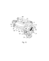
Fig.10 is a front view of a baby buggy in a folded status with omitting the right push rod; - Wherein, 1. a front wheel bracket; 2. a connecting seat; 3. right rear wheel bracket; 5. left rear wheel bracket; 6. a right push rod; 7. a left push rod; 8. a sliding part; 9. a right rear supporting rod; 10. a left front wheel rod; 11. a left rear supporting rod; 12. a first driving rod; 13. a second driving rod; 14. front wheel assemblies; 15. a right rear wheel assembly; 16. a left rear wheel assembly; 17. a transverse brace; 18. a right push handle; 19. a left push handle; 20. a right front wheel rod; 21. a first rotating shaft; 22. a second rotating shaft; 23. a third rotating shaft; 24. a fourth rotating shaft; 25. a fifth rotating shaft; 26. a sixth rotating shaft; 27. a seventh rotating shaft; 28. a eighth rotating shaft; 29. a ninth rotating shaft; 30. a tenth rotating shaft; 31. a eleventh rotating shaft; 32. a twelfth rotating shaft; a. a first plane; b. a second plane.
- Referring to the embodiments shown in
figs. 1 to 10 , the baby buggy comprises a frame provided with an unfolded position and a folded position;front wheel assemblies 14; a rightrear wheel assembly 15; a leftrear wheel assembly 16; a locking device for locking the frame in an unfolded position; and a seat (not shown) set on the frame for children sitting or lying. The words of "front", "rear", "left" and "right" referring to orientation herein and hereinafter are defined according to the impression of a user, the further side from he/she is designated as "front", the side adjacent to he/she is designated as "rear", the side on his/her left is designated as "left", and the side on his/her right is designated as "right". - As shown in figures, the frame comprises:
- a
front wheel bracket 1 having front wheel rods extending along an anteroposterior direction, thefront wheel assemblies 14 are arranged below the front portions of which, in this embodiment, - two
front wheel assemblies 14 are respectively arranged below the front portions of the left and right sides of thefront wheel bracket 1; - a right
rear wheel bracket 3, the upper portion of which is rotatably connected to the right side of the rear portion of thefront wheel bracket 1 by a firstrotating shaft 21, and the lower portion of which is provided with the rightrear wheel assembly 15; - a left
rear wheel bracket 5, as shown infig. 4 , the upper portion of which is rotatably connected to the left side of the rear portion of thefront wheel bracket 1 by a second rotating shaft 22, and the lower portion of which is provided with the leftrear wheel assembly 16; - a
right push rod 6; - a
left push rod 7; - a sliding
part 8, which is slidably arranged on the front wheel rods along the anteroposterior direction thereof; - a right
rear supporting rod 9, the upper portion of which is rotatably connected to theright push rod 6 by a seventhrotating shaft 27, and the lower portion of which is rotatably connected to the right side of the rear portion of thefront wheel bracket 1 by a thirdrotating shaft 23; - a left
rear supporting rod 11, the upper portion of which is rotatably connected to theleft push rod 7 by a eighthrotating shaft 28, and the lower portion of which is rotatably connected to the left side of the rear portion of thefront wheel bracket 1 by a fourthrotating shaft 24; - a
first driving rod 12, as shown infig. 3 , being rotatably connected to the slidingpart 8 by a fifthrotating shaft 25, the upper portion of which is rotatalby to the lower portion of theright push rod 6 by a ninthrotating shaft 29, as shown infigs. 4-5 , and the lower portion of which is rotatably connected to the leftrear wheel bracket 5 by a twelfthrotating shaft 32; - a
second driving rod 13 being rotatably connected to the slidingpart 8 by a sixthrotating shaft 26, the upper portion of which is rotatably connected to the lower portion of theleft push rod 7 by a tenthrotating shaft 30, and the lower portion of which is rotatably connected to the rightrear wheel bracket 3 by a eleventhrotating shaft 31; - As shown in
figs. 2-4 , the shaft axes of the second rotating shaft 22, thirdrotating shaft 23, fifthrotating shaft 25, seventhrotating shaft 27, ninthrotating shaft 29 and the twelfthrotating shaft 32 are parallel to each other, and the plane perpendicular to such shaft axes is defined as a first plane a, as shown infig. 4 , the shaft axes of the firstrotating shaft 21, fourthrotating shaft 24, sixthrotating shaft 26, eighthrotating shaft 28, tenthrotating shaft 30 and the eleventhrotating shaft 31 are parallel to each other, and the plane perpendicular to such shaft axes is defined as a second plane b, wherein the first plane a and second plane b intersects with each other. - The frame also includes a transversely foldable
transverse brace 17 which make the rigidity during theright push rod 6 and theleft push rod 7 stronger when the frame is in an unfolded position. - As shown in figures, the frame also comprises a right push handle 18 with the lower end being rotatably connected to the
right push rod 6, and a left push handle 19 with the lower end being rotatably connected to the upper end of theleft push rod 7 , wherein the right end of thetransverse brace 17 is rotatably connected to the right push handle 18, and the left end of thetransverse brace 17 is rotatably connected to theleft push handle 19, in the course of frame folding, the right push handle 18 folds towards theright push rod 6, and the left push handle 19 folds towards theleft push rod 7, the volume of the frame becomes smaller after folding. Alternatively, the right push handle 18 is slidably connected to theright push rod 6, and the left push handle 19 is slidably connected to theleft push rod 7, thus, the volume of frame after folding can be reduced by shrinking slidably. Or alternatively, the right push handle 18 and theright push rod 6 are one-piece, and the left push handle 19 and theleft push rod 7 are one-piece, thus, the volume of the frame after folding is big. Thetransverse brace 17 includes a first transverse brace rod and a second transverse brace rod, wherein the inner end of the first transverse brace rod is rotatably connected to the inner end of the second transverse brace rod, and the outer end of the first transverse brace rod is rotatably connected to the right push handle 18, and the outer end of the second transverse brace rod is rotatably connected to theleft push handle 19. Thetransverse brace 17 also can be arranged between theleft push rod 7 and theright push rod 6. - The third
rotating shaft 23 is located above the firstrotating shaft 21, and the fourthrotating shaft 24 is located above the second rotating shaft 22. - The front wheel rods include a left
front wheel rod 20 positioned at the left side of thefront wheel bracket 1 and a rightfront wheel rod 10 positioned at the right side of thefront wheel bracket 1. The leftfront wheel rod 20 and the rightfront wheel rod 10 are set fixedly forming a whole. A left through hole and a right through hole respectively are opened at the left and right sides of the slidingpart 8, the leftfront wheel rod 20 is inserted into the left through hole and the rightfront wheel rod 10 is inserted into the right through hole. Thefirst driving rod 12 and thesecond driving rod 13 are situated between the leftfront wheel rod 20 and the rightfront wheel rod 10. Thefront wheel bracket 1 further includes a connectingseat 2 positioned at the rear portion thereof, the connectingseat 2 is connected fixedly to the front wheel rods. - The
first driving shaft 12 is rotatably connected to the right side of the slidingpart 8 by a fifthrotating shaft 25, and thesecond driving shaft 13 is rotatably connected to the left side of the slidingpart 8 by a sixthrotating shaft 26. - In the course of folding, pressing down the
right push rod 6 and leftpush rod 7 make both the rightrear supporting rod 9 and leftrear supporting rod 11 turn forwards, meanwhile, theright push rod 6 and leftpush rod 7 respectively drives thefirst driving rod 12 and thesecond driving rod 13 moving downwards, and thus drives the slidingpart 8 sliding down, and the leftrear wheel bracket 3 and the rightrear wheel bracket 5 turning forwards, besides, the rightrear wheel bracket 3 and the leftrear wheel bracket 5 draw close to each other, theright push rod 6 and theleft push rod 7 draw close to each other, and the rightrear supporting rod 9 and the leftrear supporting rod 11 also draw close to each other, and accordingly the folding is achieved. The volume of frame after folding is small. - As described above, the detailed description is illustrated according to the spirit of the invention fully, but the present invention is not limited to the aforementioned embodiments and implementing methods. Many variations and implements can be made within the scope of the invention by those skilled in the related art.
Claims (10)
- A baby buggy comprising a foldable frame, a locking device for locking said frame, wheel assemblies disposed at the bottom of the frame, and a seat set on the frame, wherein the frame comprises:a front wheel bracket (1) having front wheel rods extending along an anteroposterior direction;a right rear wheel bracket (3), which is rotatably connected at its upper portion to a rear portion of the front wheel bracket (1) by a first rotating shaft (21);a left rear wheel bracket (5), which is rotatably connected at its upper portion to the rear portion of the front wheel bracket (1) by a second rotating shaft (22);a right push rod (6);a left push rod (7);a sliding part (8), which is slidably arranged on the front wheel rods along the anteroposterior direction thereof;a right rear supporting rod (9), which is rotatably connected at its upper portion to the right push rod (6) by a seventh rotating shaft (27), and rotatably connected at its lower portion to the rear portion of the front wheel bracket (1) by a third rotating shaft (23);a left rear supporting rod (11), which is rotatably connected at its upper portion to the left push rod (7) by an eighth rotating shaft (28), and rotatably connected at its lower portion to the rear portion of the front wheel bracket (1) by a fourth rotating shaft (24);a first driving rod (12), which is rotatably connected to the sliding part (8) by a fifth rotating shaft (25), the first driving rod (12) being rotatably connected at its upper portion to a lower portion of the right push rod (6) by a ninth rotating shaft (29), and rotatably connected at its lower portion to the left rear wheel bracket (5) by a twelfth rotating shaft (32); anda second driving rod (13) which is rotatably connected to the sliding part (8) by a sixth rotating shaft (26), the second driving rod (13) being rotatably connected at its upper portion to a lower portion of the left push rod (7) by a tenth rotating shaft (30), and rotatably connected at its lower portion to the right rear wheel bracket (3) by an eleventh rotating shaft (31).
- The baby buggy as claimed in claim 1, wherein a first plane (a) which is perpendicular to the axes of the second rotating shaft (22), the third rotating shaft (23), the fifth rotating shaft (25), the seventh rotating shaft (27), the ninth rotating shaft (29), and the twelfth rotating shaft (32) which are parallel to each other, intersects with a second plane (b) which is perpendicular to the axes of the first rotating shaft (21), fourth rotating shaft (24), sixth rotating shaft (26), eighth rotating shaft (28), tenth rotating shaft (30) and the eleventh rotating shaft (31) which are parallel to each other.
- The baby buggy as claimed in claim 1, wherein the frame further includes a foldable transverse brace (17) for laterally supporting the left push rod (7) and the right push rod (6).
- The baby buggy as claimed in claim 3, wherein the frame further includes
a right push handle (18) with a lower end being rotatably connected to an upper end of the right push rod (6); and
a left push handle (19) with a lower end being rotatably connected to an upper end of the left push rod (7);
wherein the two ends of the transverse brace (17) respectively being rotatably connected to the right push handle (18) and the left push handle (19). - The baby buggy as claimed in claim 1, wherein the third rotating shaft (23) is located above the first rotating shaft (21), and the fourth rotating shaft (24) islocated above the second rotating shaft (22).
- The baby buggy as claimed in claim 1, wherein the front wheel rods include
a left front wheel rod (20) positioned at the left side of the front wheel bracket (1), which is inserted into a left through hole opened at the left side of the sliding part (8); and
a right front wheel rod (10) positioned at the right side of the front wheel bracket (1), which is inserted into a right through hole opened at the right side of the sliding part (8). - The baby buggy as claimed in claim 6, wherein the left front wheel rod (20) and the right front wheel rod (10) are fixed to each other to form anintegration.
- The baby buggy as claimed in claim 6, wherein the first driving rod (12) and the second driving rod (13) are situated between the left front wheel rod (20) and the right front wheel rod (10).
- The baby buggy as claimed in claim 6, wherein the front wheel bracket (1) further includes a connecting seat (2) at its rear portion, which is connected fixedly to the rear portions of the front wheel rods.
- The baby buggy as claimed in any of claims 1-9, wherein the first driving shaft (12) is rotatably connected to the right side of the sliding part (8) by a fifth rotating shaft (25), and the second driving shaft (13) is rotatably connected to the left side of the sliding part (8) by a sixth rotating shaft (26).
Applications Claiming Priority (2)
| Application Number | Priority Date | Filing Date | Title |
|---|---|---|---|
| CN2010100042294A CN101734272B (en) | 2010-01-12 | 2010-01-12 | Children cart |
| PCT/CN2010/080646 WO2011085635A1 (en) | 2010-01-12 | 2010-12-31 | Baby carriage |
Publications (3)
| Publication Number | Publication Date |
|---|---|
| EP2524853A1 true EP2524853A1 (en) | 2012-11-21 |
| EP2524853A4 EP2524853A4 (en) | 2013-07-24 |
| EP2524853B1 EP2524853B1 (en) | 2018-08-29 |
Family
ID=42458466
Family Applications (1)
| Application Number | Title | Priority Date | Filing Date |
|---|---|---|---|
| EP10842917.6A Not-in-force EP2524853B1 (en) | 2010-01-12 | 2010-12-31 | Baby carriage |
Country Status (4)
| Country | Link |
|---|---|
| US (1) | US8579319B2 (en) |
| EP (1) | EP2524853B1 (en) |
| CN (1) | CN101734272B (en) |
| WO (1) | WO2011085635A1 (en) |
Cited By (1)
| Publication number | Priority date | Publication date | Assignee | Title |
|---|---|---|---|---|
| CN104527760A (en) * | 2014-12-20 | 2015-04-22 | 柯全德 | Baby carriage structure |
Families Citing this family (7)
| Publication number | Priority date | Publication date | Assignee | Title |
|---|---|---|---|---|
| CN101734272B (en) * | 2010-01-12 | 2011-11-16 | 好孩子儿童用品有限公司 | Children cart |
| CN103085850B (en) * | 2011-10-27 | 2015-06-24 | 明门(中国)幼童用品有限公司 | Stroller frame |
| EP2684768B1 (en) | 2012-07-13 | 2019-03-13 | Thule Child Transport Systems Ltd | A passenger carrier with an accessory cross bar |
| EP2684766B1 (en) * | 2012-07-13 | 2018-07-04 | Thule Child Transport Systems Ltd | Foldable passenger carrier |
| USD704600S1 (en) | 2012-12-21 | 2014-05-13 | Thule Child Transport Systems Ltd. | Passenger carriage device |
| CN104260770A (en) * | 2014-09-10 | 2015-01-07 | 好孩子儿童用品有限公司 | Folding cart |
| US9796404B2 (en) * | 2015-08-21 | 2017-10-24 | Dongguan Master Kids Toy Co., Ltd | Interlocking folding component and method thereof for strollers |
Family Cites Families (18)
| Publication number | Priority date | Publication date | Assignee | Title |
|---|---|---|---|---|
| CN2263615Y (en) * | 1996-08-22 | 1997-10-01 | 好孩子集团公司 | Perambulator with umbrella handle |
| US5765855A (en) * | 1996-08-26 | 1998-06-16 | Chiu; Ping-Jan | Foldable stroller |
| EP0941908B1 (en) * | 1996-12-19 | 2002-03-13 | Form Design Corporation | Suspension for stroller |
| US5979928A (en) * | 1997-04-02 | 1999-11-09 | Taiwan Kidly Children Appliance Ltd. | Collapsing device for a stroller |
| GB2361677B (en) * | 2000-04-28 | 2002-07-17 | Red Lan | Mounting device for mounting a front wheel axle on a stroller frame |
| CN1218853C (en) * | 2002-04-08 | 2005-09-14 | 好孩子儿童用品有限公司 | stroller |
| CN2693591Y (en) * | 2004-02-02 | 2005-04-20 | 好孩子儿童用品有限公司 | Collapsible baby carriage |
| CN2741847Y (en) * | 2004-11-03 | 2005-11-23 | 好孩子儿童用品有限公司 | Child pushing cart |
| DE202005013899U1 (en) * | 2005-05-06 | 2005-11-10 | Hutchinson, James M.F. | Foldable buggy rack used to transport buggy in a motor vehicle, has swiveling supports connected in swiveling manner to front legs and rear legs with use of rear wheel connecting links |
| PT1741614E (en) * | 2005-07-07 | 2010-09-02 | Jane Sa | A foldable chassis for baby carriages |
| TWM281865U (en) * | 2005-07-12 | 2005-12-01 | Link Treasure Ltd | Direction control device for swivel wheels of baby stroller |
| TWM288610U (en) * | 2005-10-19 | 2006-03-11 | Link Treasure Ltd | Collapsible framework structure for infant jogging stroller |
| CN100366489C (en) * | 2005-11-08 | 2008-02-06 | 好孩子儿童用品有限公司 | Children's cart |
| CN1792694A (en) * | 2005-12-22 | 2006-06-28 | 好孩子儿童用品有限公司 | Children carriage |
| US7735843B2 (en) * | 2006-04-03 | 2010-06-15 | Graco Children's Products Inc. | Stroller brake system |
| CN201587438U (en) * | 2010-01-12 | 2010-09-22 | 好孩子儿童用品有限公司 | a stroller |
| CN101734272B (en) * | 2010-01-12 | 2011-11-16 | 好孩子儿童用品有限公司 | Children cart |
| US8696016B2 (en) * | 2010-04-01 | 2014-04-15 | Nuna International, B.V. | Collapsible stroller apparatus |
-
2010
- 2010-01-12 CN CN2010100042294A patent/CN101734272B/en active Active
- 2010-12-31 US US13/521,719 patent/US8579319B2/en not_active Expired - Fee Related
- 2010-12-31 EP EP10842917.6A patent/EP2524853B1/en not_active Not-in-force
- 2010-12-31 WO PCT/CN2010/080646 patent/WO2011085635A1/en not_active Ceased
Cited By (2)
| Publication number | Priority date | Publication date | Assignee | Title |
|---|---|---|---|---|
| CN104527760A (en) * | 2014-12-20 | 2015-04-22 | 柯全德 | Baby carriage structure |
| CN104527760B (en) * | 2014-12-20 | 2017-04-12 | 柯全德 | Baby carriage structure |
Also Published As
| Publication number | Publication date |
|---|---|
| EP2524853A4 (en) | 2013-07-24 |
| US20130119641A1 (en) | 2013-05-16 |
| US8579319B2 (en) | 2013-11-12 |
| CN101734272A (en) | 2010-06-16 |
| WO2011085635A1 (en) | 2011-07-21 |
| CN101734272B (en) | 2011-11-16 |
| EP2524853B1 (en) | 2018-08-29 |
Similar Documents
| Publication | Publication Date | Title |
|---|---|---|
| US8579319B2 (en) | Baby carriage | |
| EP2949543B1 (en) | Stroller | |
| EP2248707B1 (en) | Baby buggy | |
| EP2014536B1 (en) | Foldable toy stroller | |
| EP2441646A1 (en) | Carrier and baby carriage | |
| EP2052945A1 (en) | Foldable pushcart | |
| EP2700559B1 (en) | Foldable stroller frame | |
| EP2762383B1 (en) | Push chair for children | |
| WO2007071141A1 (en) | A pushcart for infants | |
| JP5020655B2 (en) | stroller | |
| CN102001350B (en) | Baby stroller | |
| CN201907546U (en) | Perambulator | |
| CN201587438U (en) | a stroller | |
| EP1972522B1 (en) | A foldable pushchair for babies and small children | |
| CN201951515U (en) | Baby cart | |
| CN203228817U (en) | Child stroller | |
| CN102416973B (en) | a stroller | |
| CN101797932B (en) | Stroller for children | |
| EP2878512A1 (en) | Child seat bag and child stroller | |
| CN201685856U (en) | stroller | |
| CN102514608B (en) | Trolley for children | |
| CN202686429U (en) | Stroller for children | |
| CN217892955U (en) | a stroller for children | |
| CN202400131U (en) | Baby carrier | |
| CN110775185B (en) | Folding stroller |
Legal Events
| Date | Code | Title | Description |
|---|---|---|---|
| PUAI | Public reference made under article 153(3) epc to a published international application that has entered the european phase |
Free format text: ORIGINAL CODE: 0009012 |
|
| 17P | Request for examination filed |
Effective date: 20120730 |
|
| AK | Designated contracting states |
Kind code of ref document: A1 Designated state(s): AL AT BE BG CH CY CZ DE DK EE ES FI FR GB GR HR HU IE IS IT LI LT LU LV MC MK MT NL NO PL PT RO RS SE SI SK SM TR |
|
| DAX | Request for extension of the european patent (deleted) | ||
| A4 | Supplementary search report drawn up and despatched |
Effective date: 20130625 |
|
| RIC1 | Information provided on ipc code assigned before grant |
Ipc: B62B 7/06 20060101AFI20130619BHEP Ipc: B62B 7/10 20060101ALI20130619BHEP |
|
| 17Q | First examination report despatched |
Effective date: 20170313 |
|
| GRAP | Despatch of communication of intention to grant a patent |
Free format text: ORIGINAL CODE: EPIDOSNIGR1 |
|
| INTG | Intention to grant announced |
Effective date: 20180423 |
|
| GRAS | Grant fee paid |
Free format text: ORIGINAL CODE: EPIDOSNIGR3 |
|
| GRAA | (expected) grant |
Free format text: ORIGINAL CODE: 0009210 |
|
| AK | Designated contracting states |
Kind code of ref document: B1 Designated state(s): AL AT BE BG CH CY CZ DE DK EE ES FI FR GB GR HR HU IE IS IT LI LT LU LV MC MK MT NL NO PL PT RO RS SE SI SK SM TR |
|
| REG | Reference to a national code |
Ref country code: GB Ref legal event code: FG4D |
|
| REG | Reference to a national code |
Ref country code: CH Ref legal event code: EP |
|
| REG | Reference to a national code |
Ref country code: AT Ref legal event code: REF Ref document number: 1034771 Country of ref document: AT Kind code of ref document: T Effective date: 20180915 |
|
| REG | Reference to a national code |
Ref country code: IE Ref legal event code: FG4D |
|
| REG | Reference to a national code |
Ref country code: DE Ref legal event code: R096 Ref document number: 602010053207 Country of ref document: DE |
|
| REG | Reference to a national code |
Ref country code: NL Ref legal event code: MP Effective date: 20180829 |
|
| REG | Reference to a national code |
Ref country code: LT Ref legal event code: MG4D |
|
| PG25 | Lapsed in a contracting state [announced via postgrant information from national office to epo] |
Ref country code: FI Free format text: LAPSE BECAUSE OF FAILURE TO SUBMIT A TRANSLATION OF THE DESCRIPTION OR TO PAY THE FEE WITHIN THE PRESCRIBED TIME-LIMIT Effective date: 20180829 Ref country code: GR Free format text: LAPSE BECAUSE OF FAILURE TO SUBMIT A TRANSLATION OF THE DESCRIPTION OR TO PAY THE FEE WITHIN THE PRESCRIBED TIME-LIMIT Effective date: 20181130 Ref country code: RS Free format text: LAPSE BECAUSE OF FAILURE TO SUBMIT A TRANSLATION OF THE DESCRIPTION OR TO PAY THE FEE WITHIN THE PRESCRIBED TIME-LIMIT Effective date: 20180829 Ref country code: IS Free format text: LAPSE BECAUSE OF FAILURE TO SUBMIT A TRANSLATION OF THE DESCRIPTION OR TO PAY THE FEE WITHIN THE PRESCRIBED TIME-LIMIT Effective date: 20181229 Ref country code: SE Free format text: LAPSE BECAUSE OF FAILURE TO SUBMIT A TRANSLATION OF THE DESCRIPTION OR TO PAY THE FEE WITHIN THE PRESCRIBED TIME-LIMIT Effective date: 20180829 Ref country code: LT Free format text: LAPSE BECAUSE OF FAILURE TO SUBMIT A TRANSLATION OF THE DESCRIPTION OR TO PAY THE FEE WITHIN THE PRESCRIBED TIME-LIMIT Effective date: 20180829 Ref country code: BG Free format text: LAPSE BECAUSE OF FAILURE TO SUBMIT A TRANSLATION OF THE DESCRIPTION OR TO PAY THE FEE WITHIN THE PRESCRIBED TIME-LIMIT Effective date: 20181129 Ref country code: NL Free format text: LAPSE BECAUSE OF FAILURE TO SUBMIT A TRANSLATION OF THE DESCRIPTION OR TO PAY THE FEE WITHIN THE PRESCRIBED TIME-LIMIT Effective date: 20180829 Ref country code: NO Free format text: LAPSE BECAUSE OF FAILURE TO SUBMIT A TRANSLATION OF THE DESCRIPTION OR TO PAY THE FEE WITHIN THE PRESCRIBED TIME-LIMIT Effective date: 20181129 |
|
| REG | Reference to a national code |
Ref country code: AT Ref legal event code: MK05 Ref document number: 1034771 Country of ref document: AT Kind code of ref document: T Effective date: 20180829 |
|
| PG25 | Lapsed in a contracting state [announced via postgrant information from national office to epo] |
Ref country code: HR Free format text: LAPSE BECAUSE OF FAILURE TO SUBMIT A TRANSLATION OF THE DESCRIPTION OR TO PAY THE FEE WITHIN THE PRESCRIBED TIME-LIMIT Effective date: 20180829 Ref country code: LV Free format text: LAPSE BECAUSE OF FAILURE TO SUBMIT A TRANSLATION OF THE DESCRIPTION OR TO PAY THE FEE WITHIN THE PRESCRIBED TIME-LIMIT Effective date: 20180829 Ref country code: AL Free format text: LAPSE BECAUSE OF FAILURE TO SUBMIT A TRANSLATION OF THE DESCRIPTION OR TO PAY THE FEE WITHIN THE PRESCRIBED TIME-LIMIT Effective date: 20180829 |
|
| PG25 | Lapsed in a contracting state [announced via postgrant information from national office to epo] |
Ref country code: ES Free format text: LAPSE BECAUSE OF FAILURE TO SUBMIT A TRANSLATION OF THE DESCRIPTION OR TO PAY THE FEE WITHIN THE PRESCRIBED TIME-LIMIT Effective date: 20180829 Ref country code: EE Free format text: LAPSE BECAUSE OF FAILURE TO SUBMIT A TRANSLATION OF THE DESCRIPTION OR TO PAY THE FEE WITHIN THE PRESCRIBED TIME-LIMIT Effective date: 20180829 Ref country code: AT Free format text: LAPSE BECAUSE OF FAILURE TO SUBMIT A TRANSLATION OF THE DESCRIPTION OR TO PAY THE FEE WITHIN THE PRESCRIBED TIME-LIMIT Effective date: 20180829 Ref country code: IT Free format text: LAPSE BECAUSE OF FAILURE TO SUBMIT A TRANSLATION OF THE DESCRIPTION OR TO PAY THE FEE WITHIN THE PRESCRIBED TIME-LIMIT Effective date: 20180829 Ref country code: RO Free format text: LAPSE BECAUSE OF FAILURE TO SUBMIT A TRANSLATION OF THE DESCRIPTION OR TO PAY THE FEE WITHIN THE PRESCRIBED TIME-LIMIT Effective date: 20180829 Ref country code: CZ Free format text: LAPSE BECAUSE OF FAILURE TO SUBMIT A TRANSLATION OF THE DESCRIPTION OR TO PAY THE FEE WITHIN THE PRESCRIBED TIME-LIMIT Effective date: 20180829 Ref country code: PL Free format text: LAPSE BECAUSE OF FAILURE TO SUBMIT A TRANSLATION OF THE DESCRIPTION OR TO PAY THE FEE WITHIN THE PRESCRIBED TIME-LIMIT Effective date: 20180829 |
|
| PG25 | Lapsed in a contracting state [announced via postgrant information from national office to epo] |
Ref country code: SM Free format text: LAPSE BECAUSE OF FAILURE TO SUBMIT A TRANSLATION OF THE DESCRIPTION OR TO PAY THE FEE WITHIN THE PRESCRIBED TIME-LIMIT Effective date: 20180829 Ref country code: DK Free format text: LAPSE BECAUSE OF FAILURE TO SUBMIT A TRANSLATION OF THE DESCRIPTION OR TO PAY THE FEE WITHIN THE PRESCRIBED TIME-LIMIT Effective date: 20180829 Ref country code: SK Free format text: LAPSE BECAUSE OF FAILURE TO SUBMIT A TRANSLATION OF THE DESCRIPTION OR TO PAY THE FEE WITHIN THE PRESCRIBED TIME-LIMIT Effective date: 20180829 |
|
| REG | Reference to a national code |
Ref country code: DE Ref legal event code: R097 Ref document number: 602010053207 Country of ref document: DE |
|
| PLBE | No opposition filed within time limit |
Free format text: ORIGINAL CODE: 0009261 |
|
| STAA | Information on the status of an ep patent application or granted ep patent |
Free format text: STATUS: NO OPPOSITION FILED WITHIN TIME LIMIT |
|
| REG | Reference to a national code |
Ref country code: CH Ref legal event code: PL |
|
| 26N | No opposition filed |
Effective date: 20190531 |
|
| PG25 | Lapsed in a contracting state [announced via postgrant information from national office to epo] |
Ref country code: SI Free format text: LAPSE BECAUSE OF FAILURE TO SUBMIT A TRANSLATION OF THE DESCRIPTION OR TO PAY THE FEE WITHIN THE PRESCRIBED TIME-LIMIT Effective date: 20180829 Ref country code: LU Free format text: LAPSE BECAUSE OF NON-PAYMENT OF DUE FEES Effective date: 20181231 Ref country code: MC Free format text: LAPSE BECAUSE OF FAILURE TO SUBMIT A TRANSLATION OF THE DESCRIPTION OR TO PAY THE FEE WITHIN THE PRESCRIBED TIME-LIMIT Effective date: 20180829 |
|
| REG | Reference to a national code |
Ref country code: IE Ref legal event code: MM4A |
|
| REG | Reference to a national code |
Ref country code: BE Ref legal event code: MM Effective date: 20181231 |
|
| PG25 | Lapsed in a contracting state [announced via postgrant information from national office to epo] |
Ref country code: FR Free format text: LAPSE BECAUSE OF NON-PAYMENT OF DUE FEES Effective date: 20181231 Ref country code: IE Free format text: LAPSE BECAUSE OF NON-PAYMENT OF DUE FEES Effective date: 20181231 |
|
| PG25 | Lapsed in a contracting state [announced via postgrant information from national office to epo] |
Ref country code: BE Free format text: LAPSE BECAUSE OF NON-PAYMENT OF DUE FEES Effective date: 20181231 |
|
| PG25 | Lapsed in a contracting state [announced via postgrant information from national office to epo] |
Ref country code: LI Free format text: LAPSE BECAUSE OF NON-PAYMENT OF DUE FEES Effective date: 20181231 Ref country code: CH Free format text: LAPSE BECAUSE OF NON-PAYMENT OF DUE FEES Effective date: 20181231 |
|
| PG25 | Lapsed in a contracting state [announced via postgrant information from national office to epo] |
Ref country code: MT Free format text: LAPSE BECAUSE OF NON-PAYMENT OF DUE FEES Effective date: 20181231 |
|
| PG25 | Lapsed in a contracting state [announced via postgrant information from national office to epo] |
Ref country code: TR Free format text: LAPSE BECAUSE OF FAILURE TO SUBMIT A TRANSLATION OF THE DESCRIPTION OR TO PAY THE FEE WITHIN THE PRESCRIBED TIME-LIMIT Effective date: 20180829 |
|
| PG25 | Lapsed in a contracting state [announced via postgrant information from national office to epo] |
Ref country code: PT Free format text: LAPSE BECAUSE OF FAILURE TO SUBMIT A TRANSLATION OF THE DESCRIPTION OR TO PAY THE FEE WITHIN THE PRESCRIBED TIME-LIMIT Effective date: 20180829 |
|
| PG25 | Lapsed in a contracting state [announced via postgrant information from national office to epo] |
Ref country code: HU Free format text: LAPSE BECAUSE OF FAILURE TO SUBMIT A TRANSLATION OF THE DESCRIPTION OR TO PAY THE FEE WITHIN THE PRESCRIBED TIME-LIMIT; INVALID AB INITIO Effective date: 20101231 Ref country code: CY Free format text: LAPSE BECAUSE OF FAILURE TO SUBMIT A TRANSLATION OF THE DESCRIPTION OR TO PAY THE FEE WITHIN THE PRESCRIBED TIME-LIMIT Effective date: 20180829 Ref country code: MK Free format text: LAPSE BECAUSE OF NON-PAYMENT OF DUE FEES Effective date: 20180829 |
|
| PGFP | Annual fee paid to national office [announced via postgrant information from national office to epo] |
Ref country code: GB Payment date: 20221227 Year of fee payment: 13 |
|
| PGFP | Annual fee paid to national office [announced via postgrant information from national office to epo] |
Ref country code: DE Payment date: 20231229 Year of fee payment: 14 |
|
| GBPC | Gb: european patent ceased through non-payment of renewal fee |
Effective date: 20231231 |
|
| PG25 | Lapsed in a contracting state [announced via postgrant information from national office to epo] |
Ref country code: GB Free format text: LAPSE BECAUSE OF NON-PAYMENT OF DUE FEES Effective date: 20231231 |
|
| PG25 | Lapsed in a contracting state [announced via postgrant information from national office to epo] |
Ref country code: GB Free format text: LAPSE BECAUSE OF NON-PAYMENT OF DUE FEES Effective date: 20231231 |
|
| REG | Reference to a national code |
Ref country code: DE Ref legal event code: R119 Ref document number: 602010053207 Country of ref document: DE |
|
| PG25 | Lapsed in a contracting state [announced via postgrant information from national office to epo] |
Ref country code: DE Free format text: LAPSE BECAUSE OF NON-PAYMENT OF DUE FEES Effective date: 20250701 |