EP2524844A1 - Method and device to control power consumption in a windshield wiper unit - Google Patents
Method and device to control power consumption in a windshield wiper unit Download PDFInfo
- Publication number
- EP2524844A1 EP2524844A1 EP11305618A EP11305618A EP2524844A1 EP 2524844 A1 EP2524844 A1 EP 2524844A1 EP 11305618 A EP11305618 A EP 11305618A EP 11305618 A EP11305618 A EP 11305618A EP 2524844 A1 EP2524844 A1 EP 2524844A1
- Authority
- EP
- European Patent Office
- Prior art keywords
- max
- current consumption
- wiping
- value
- threshold value
- Prior art date
- Legal status (The legal status is an assumption and is not a legal conclusion. Google has not performed a legal analysis and makes no representation as to the accuracy of the status listed.)
- Granted
Links
Images



Classifications
-
- B—PERFORMING OPERATIONS; TRANSPORTING
- B60—VEHICLES IN GENERAL
- B60S—SERVICING, CLEANING, REPAIRING, SUPPORTING, LIFTING, OR MANOEUVRING OF VEHICLES, NOT OTHERWISE PROVIDED FOR
- B60S1/00—Cleaning of vehicles
- B60S1/02—Cleaning windscreens, windows or optical devices
- B60S1/04—Wipers or the like, e.g. scrapers
- B60S1/06—Wipers or the like, e.g. scrapers characterised by the drive
- B60S1/08—Wipers or the like, e.g. scrapers characterised by the drive electrically driven
- B60S1/0896—Wipers or the like, e.g. scrapers characterised by the drive electrically driven including control systems responsive to a vehicle driving condition, e.g. speed
-
- B—PERFORMING OPERATIONS; TRANSPORTING
- B60—VEHICLES IN GENERAL
- B60S—SERVICING, CLEANING, REPAIRING, SUPPORTING, LIFTING, OR MANOEUVRING OF VEHICLES, NOT OTHERWISE PROVIDED FOR
- B60S1/00—Cleaning of vehicles
- B60S1/02—Cleaning windscreens, windows or optical devices
- B60S1/04—Wipers or the like, e.g. scrapers
- B60S1/06—Wipers or the like, e.g. scrapers characterised by the drive
- B60S1/08—Wipers or the like, e.g. scrapers characterised by the drive electrically driven
- B60S1/0818—Wipers or the like, e.g. scrapers characterised by the drive electrically driven including control systems responsive to external conditions, e.g. by detection of moisture, dirt or the like
- B60S1/0822—Wipers or the like, e.g. scrapers characterised by the drive electrically driven including control systems responsive to external conditions, e.g. by detection of moisture, dirt or the like characterized by the arrangement or type of detection means
- B60S1/0859—Other types of detection of rain, e.g. by measuring friction or rain drop impact
Definitions
- the invention relates to a method and device to control power in a windshield wiper unit.
- the electrical consumption of the peripheral circuits such as radio, indoor ambience or pictogram lights and windshield wiper unit is only moderately relevant since the running engine reloads the battery through an alternator.
- the slightest consumption reduction means more autonomy at same battery status.
- the windscreen wiper units in use involve at least one electrical motor, setting wiper blades in motion when powered with current. When set in motion, the wiper blades wipe the surface of the windshield, in order to clean it from water or stain lowering the driver's vision.
- the invention has for object a method to control power consumption in a windshield wiper unit, the windshield wiper unit comprising :
- This method allows to adapt the wiping speed in order to realize energy savings.
- the method may have one or more of the following characteristics, taken separately or in combination.
- the wiping speed is lowered by changing the wiping mode.
- the wiping speed is lowered by lowering the instantaneous speed value during a wiping cycle.
- the threshold value is the current consumption value at a predetermined wiping speed at a predefined vehicle speed.
- the threshold value depends on the depletion level of a vehicle battery delivering the current.
- the threshold value depends on the total current delivered by the vehicle battery.
- the current consumption is estimated or measured by estimating or measuring the instantaneous current value delivered to the at least one motor.
- the current consumption is estimated or measured by averaging the instantaneous current value delivered to the at least one motor over at least one wiping cycle.
- the method comprises the steps of :
- the steps of estimating or measuring the current consumption of the at least one motor, comparing the estimated or measured current consumption value to a predetermined threshold value, and lowering the wiping speed of the blades in case the estimated or measured current consumption is greater than the threshold value are repeated in a loop.
- the controller is connected to a rain sensor, and the method is initiated on rain detection by said rain sensor.
- the invention relates to the associated windshield wiper unit comprising :
- the windshield wiper unit can comprise one or more of the following characteristics, taken separately or in combination.
- the controller comprises means to estimate or measure the depletion level of the vehicle battery, and the controller is further configured to adapt the threshold value to the depletion level of the battery.
- the controller comprises means to estimate or measure the total current delivered by the vehicle battery, and the controller is further configured to adapt the threshold value to the total current delivered by the vehicle battery.
- the invention relates to a vehicle windshield wiper unit, and more particularly to a method to manage power consumption in such a windshield wiper unit.
- Figure 1 represents schematically a windshield and the associated windshield wiper unit 1.
- the windshield 3 comprises an external surface S which receives rain or other stain from the surroundings when the vehicle is driven.
- On said surface S are placed windshield wiper blades 5.
- the blades 5 are connected to respective motors 7, the motors 7 are able to set the blades 5 in motion by applying a torque at the base of the blades 5.
- Said motors 7 are fed with electrical power via a controller 9, configured to apply specific wiping programs by controlling the wiping speed W of blades 5.
- the power to run the motors 7 is delivered by the vehicle battery 11 or by an alternator.
- the controller 9 can also be connected to a droplet detector 13.
- the droplet detector 13 is usually an optical sensor placed on the surface S using infrared dispersion and reflexion of infrared beams inside the windshield glass.
- a windshield washing unit 15 Said unit comprises a pump 17, connected to the controller 9, and configured to pump on driver request washing fluid 19 from a tank 21 to spraying nozzles 23. Said nozzles 23 direct a washing fluid spray on the windshield surface S to clear it from dust or stain.
- the wiper unit 1 is usually controlled by the driver via a lever or any form of actuator in the passenger compartment, most often near the steering wheel, or on the dashboard.
- Several wiping speeds or programs are available : off OFF, single wipe SW, intermittent INT , low speed LS and high speed HS .
- Other programs may be foreseen without difficulty. It is clear that each mode has a particular power consumption, from lowest to highest, they are ordered as follows : OFF, SW, INT, LS, HS.
- the controller controls the current delivered to the motors 7 at constant voltage value.
- the controller can use pulse width modulation.
- Lowering speed W as used herein is either switching to a lower operating mode, or decreasing the instantaneous wiping speed value within a wiping cycle.
- the controller 9 may stop the wipers.
- the power consumption also depends on one hand on the wet/dry state of the windshield surface S , and on the other hand on the vehicle speed V.
- the friction torque of the blade on surface also greatly depends on the wetness state of the windshield surface S . In particular, it is significantly lower when surface S is wet.
- FIG. 2 shows a particular embodiment of the current estimator 25 used in the present embodiments to estimate current I .
- the current estimator 25 is connected to a blade position sensor 27, measuring the blade 5 angular position via an angular motor speed estimator 29.
- Said angular motor speed estimator 29 uses the output of said blade position sensor 27 to estimate, for example via derivation the angular speed of the motor 7.
- the current estimator 25 also receives from electronics 31 the pulse width modulation PWM value determined in previous steps, the battery voltage from a battery voltmeter 33 and the estimated motor temperature from a motor thermometer 35.
- the current I can be directly measured using a current sensor.
- the current I consumption of motors 7 as a function of vehicle speed V at different wiping speeds W is represented on figure 3 .
- the motors are fed at constant voltage with a different current to adapt their mean power consumption, for example using pulse width modulation, so that the mean current I used as ordinate is directly proportional to the mean power consumption of motors 7.
- the two lowest current curves, HS wet and LS wet correspond to the mean current consumption on wet windshield surface S , respectively at high wiping speed and low wiping speed.
- the current curves at low wiping speed LS are in both surface wetness states lower than their corresponding current curves at high speed HS.
- the current curves on wet windshield surface S , HS wet and LS wet are much lower than the two current curves on dry windshield surface S, HS dry and LS dry .
- I max a particular current value, corresponding to the value of HS wet at maximum vehicle speed V max .
- Any estimated or measured current value of a consumption higher than said I max value indicates that the windshield surface S is dry, and that wiping speed W can consequently be lowered, be it in terms of instantaneous value, or in terms of mean value over a wiping cycle.
- the maximal speed V max can be chosen according either to the vehicle motor and construction conditioned highest attainable speed, or to the highest legally possible speed in the country the vehicle is driven.
- Figure 4 shows the current consumption of motors 7 as a function of time during four wiping cycles.
- Maximum allowed current I' max value is represented by a horizontal line. Part of the current curve is above said maximum current value I' max , which means that the wiping speed W has to be reduced.
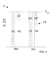
- FIG. 5 illustrates the example of a wiping speed management method according to the invention.
- the operation domains of the wiper unit 1 as a function of vehicle speed V .
- the vehicle speed V is represented along the vertical axis.
- the domains of the different operating modes LS, for low speed wiping, HS, for high speed wiping and INT for intermittent wiping are represented by vertical bar segments for the four following cases, from left to right:
- Circles mark the points where the current in motors 7 reaches maximal value, here I' max (current value for wet surface S , low speed LS wiping and maximum vehicle speed vehicle speed V max ), and where the controller 9 consequently reduces the wiping speed W to optimize current consumption.
- the operation point of the wiper unit starts at bottom of one of the columns formed by the bar segments according to the starting conditions, and goes up vertically, the operation mode ( LS, HS, INT ) changing when the operation point passes from one operation domain to another.
- the vehicle starts acceleration with a wet windshield surface S , at low speed wiping LS , corresponding to the leftmost column.
- the choice of I' max makes that on whole acceleration the wiper unit 1 remains in LS mode, until at maximum speed V max current value I' max is reached.
- the vehicle starts now with a wet windshield surface S , at high speed wiping HS , corresponding to the second column from the left.
- the aerodynamic torque increases, consequently the current consumption I increases too.
- the current reaches I' max , consequently the controller switches operation mode to LS to reduce current consumption.
- I' max makes that on the rest of the acceleration the wiper unit 1 remains in LS mode, until at maximum speed V max current value I' max is reached.
- the vehicle starts now with a dry windshield surface S , at low speed wiping LS , corresponding to the second column from the right.
- the aerodynamic torque increases, consequently the current consumption I increases too.
- the current reaches I' max , consequently the controller switches operation mode to intermittent INT to reduce current consumption.
- the current remains under maximum value I' max , so that no further change in operation mode is triggered.
- the vehicle starts now with a dry windshield surface S , at high speed wiping HS , corresponding to the rightmost column.
- the current reaches I' max , consequently the controller switches operation mode to low speed mode LS to reduce current consumption.
- the controller switches operation mode to intermittent INT to reduce once more the current consumption.
- the method is also useful at constant vehicle speed V with changing wetness conditions, for example when rain stops, or when spraying for a short moment the windshield surface S with washing fluid 19.
- Such changes of conditions at constant speed correspond to horizontal displacements from one column to the other in figure 5 .
- the driver had selected HS wiping mode because of an intense rain outburst. Said rain outburst being strong enough to maintain the windshield surface S in a sufficient wet state at said HS wiping mode. As the outburst passes, the amount of falling rain decreases, the blades 5 wiping at high speed dry up said surface S . The surface friction torque increases, I reaches I' max , and consequently the controller 9 switches operation mode to low wiping speed LS to reduce current consumption.
- the controller can also use input from different vehicle elements.
- the controller can receive information on the battery 11, and its load status.
- Information on important battery depletion, or decreasing battery voltage can be used to lower selectively the maximum allowed current value I' max in terms of averaged current consumption over at least one wiping cycle, to enhance autonomy.
- a first depletion level e. g. 50% off maximum battery load
- a second depletion level e. g. 20% off maximum battery load
- the maximum current is set at a lower value, to increase the energy savings by forbidding further energy consuming wiping modes.
- the controller 9 will compute an average value ⁇ I >, possibly RMS value, over a certain integer number of cycles, and compare said average value ⁇ I > to a threshold mean value ⁇ I > max to determine whether or not changing the wiping speed W is necessary.
- This treatment of average current consumption can be done in parallel or as an alternative to the previously described use of directly estimated or measured instantaneous current consumption I . If used with computations on mean current values, the instantaneous current consumption I can be compared to a threshold value I" max chosen according to the electric circuit components in the vehicle, in order to protect the electronics or the battery 11 itself. This allows to reduce the crest value of intensity, in order to avoid regular or long lasting strong current values.
- Figure 6 pictures the steps of an embodiment 100 of the method to manage power consumption in a wiper unit 1 that also takes in consideration the stall scenario.
- the blades 5 are mechanically blocked, for example by a layer of snow or ice.
- the current consumption quickly rises, while the wiping speed W remains zero.
- the motors 7 are supplied with a pulse width modulated current so that the relevant current value I is the mean delivered current value.
- the first step 101 of method 100 is estimating or measuring the current consumption, and computing a mean value over one cycle I .
- the controller compares said value to maximum value I max or I' max in step 103. If the determined value I is smaller than the maximum value I max , the controller maintains the current level at value I in step 105.
- the controller tests if the wiping speed W is equal to 0 in step 107. If the wiping speed is equal to 0, the wiping unit 1 is facing a stall scenario. Accordingly, the controller 9 will activate in step 109 a series of dispositions such as a stall alarm indicator, and stop delivering current to the motors 7 in step 109.
- the controller lowers the current consumption in step 111 by lowering the pulse width modulation PWM of the current delivered to the motor 7.
- the controller 9 compares the lowered pulse modulation to the nominal value for the currently selected wiping mode ( INT , HS or LS ), and in case said lowered pulse modulation is significantly smaller than said nominal value, the controller 9 switches to a lower wiping mode.
- the controller may then in any case wait for a certain time interval to elapse and return to step 101 to repeat the process in a loop.
- said sensor 13 can be configured to initiate the method 100.
- the controller 9 can be connected to the rain sensor 13.
- the rain sensor 13 detects a presence of water on the windshield surface S , it triggers the wiping and emits a starting instruction that initiates the method 100 by executing step 101.
- the method allows a form of power automatic wiper management that ensures adaptation of the current consumption in the motors 7 of the windshield wiper unit 1.
- the method allows savings of approximately 30% of the wiper unit consumption. This relevant for the case of the electrical vehicle, where both motor and peripheral circuit are all fed by the battery 11.
- the method can avoid damaging the battery 11 and other electronic components by causing too important current values to be delivered.
- the method and accompanying hardware and software are largely compliant with the already existing architectures.
- the method forms a synergy with rain sensors by confirming the presence of water on surface S by means involving a large portion of said surface S .
Landscapes
- Engineering & Computer Science (AREA)
- Automation & Control Theory (AREA)
- Mechanical Engineering (AREA)
- Electric Propulsion And Braking For Vehicles (AREA)
Abstract
- wiper blades (5) configured to wipe the windshield surface (S) when set in motion,
- at least one motor (7) configured to set the wiper blades (5) in motion,
- a controller (9), configured to control the at least one motor (7) according to a plurality of wiping modes (OFF, INT, HS, LS),
the method comprising the steps :
- estimating or measuring the current consumption of the at least one motor (7),
- comparing the estimated or measured current consumption (I) value to a predetermined threshold value (Imax , I'max ),
- lowering the wiping speed (W) of the blades (5) in case the estimated or measured current consumption (I) is greater than said threshold value (Imax , I'max ).
Description
- The invention relates to a method and device to control power in a windshield wiper unit.
- To develop electrical vehicles with a larger autonomy, two aspects are relevant. On one hand the maximum battery load, and on the other hand the average power consumption of the vehicle.
- In a normal vehicle the electrical consumption of the peripheral circuits such as radio, indoor ambiance or pictogram lights and windshield wiper unit is only moderately relevant since the running engine reloads the battery through an alternator. On the opposite, for the electrical vehicle, the slightest consumption reduction means more autonomy at same battery status.
- The windscreen wiper units in use involve at least one electrical motor, setting wiper blades in motion when powered with current. When set in motion, the wiper blades wipe the surface of the windshield, in order to clean it from water or stain lowering the driver's vision.
- On a dry windshield surface, the friction forces are more important, while wiping has become useless. This leads to increased power consumption, and faster blade wearing off if the driver forgets to stop the wiping or if it is unnecessarily switched on. It is therefore known to use a water droplet or water film detector, often based on an optical sensor, which is placed somewhere on the windshield surface.
- Also, with increasing vehicle speed, the aerodynamic force of the air flow on the blades increases, which further increases the power consumption of the motors.
- In order to overcome at least partially the aforementioned drawbacks by optimizing power consumption of a windshield wiper unit, the invention has for object a method to control power consumption in a windshield wiper unit, the windshield wiper unit comprising :
- wiper blades configured to wipe the windshield surface when set in motion,
- at least one motor configured to set the wiper blades in motion,
- a controller, configured to control the at least one motor according to a plurality of wiping modes,
- estimating or measuring the current consumption of the at least one motor,
- comparing the estimated or measured current consumption value to a predetermined threshold value,
- lowering the wiping speed of the blades in case the estimated or measured current consumption is greater than the threshold value.
- This method allows to adapt the wiping speed in order to realize energy savings.
- The method may have one or more of the following characteristics, taken separately or in combination.
- The wiping speed is lowered by changing the wiping mode.
- The wiping speed is lowered by lowering the instantaneous speed value during a wiping cycle.
- The threshold value is the current consumption value at a predetermined wiping speed at a predefined vehicle speed.
- The threshold value depends on the depletion level of a vehicle battery delivering the current.
- The threshold value depends on the total current delivered by the vehicle battery.
- The current consumption is estimated or measured by estimating or measuring the instantaneous current value delivered to the at least one motor.
- The current consumption is estimated or measured by averaging the instantaneous current value delivered to the at least one motor over at least one wiping cycle.
- The method comprises the steps of :
- estimating or measuring the instantaneous current consumption,
- estimating or measuring an average current consumption value over at least one wiping cycle,
- comparing the instantaneous current consumption to a first threshold value determined according to the electric circuit components in the vehicle, in order to protect the electronics or the battery,
- comparing the average current consumption value to a second threshold value determined to allow battery load savings,
- lowering the wiping speed of the blades in case the estimated or measured current consumption is greater than the threshold value by changing the wiping mode.
- It further comprises the steps :
- determining if the wiping speed is zero,
- triggering a stall alert and stop delivering current to the at least one motor if the wiping speed is zero.
- The steps of estimating or measuring the current consumption of the at least one motor, comparing the estimated or measured current consumption value to a predetermined threshold value, and lowering the wiping speed of the blades in case the estimated or measured current consumption is greater than the threshold value are repeated in a loop.
- The controller is connected to a rain sensor, and the method is initiated on rain detection by said rain sensor.
- Also, the invention relates to the associated windshield wiper unit comprising :
- wiper blades configured to wipe the windshield surface when set in motion,
- at least one motor configured to set the wiper blades in motion,
- a controller, configured to control the at least one motor,
- estimate or measure the current consumption of the at least one motor,
- compare the estimated or measured current consumption value to a predetermined threshold value,
- lower the wiping speed of the blades in case the estimated or measured current consumption is greater than the threshold value.
- The windshield wiper unit can comprise one or more of the following characteristics, taken separately or in combination.
- The controller comprises means to estimate or measure the depletion level of the vehicle battery, and the controller is further configured to adapt the threshold value to the depletion level of the battery.
- The controller comprises means to estimate or measure the total current delivered by the vehicle battery, and the controller is further configured to adapt the threshold value to the total current delivered by the vehicle battery.
- Other characteristics and advantages will appear at the reading of the following description of the accompanying figures, among which :
-
Figure 1 is a schematic view of a windshield wiping unit, -
Figure 2 is a schematic representation of a current estimator as used in the invention, -
Figure 3 is a simplified graph representing the power consumption as a function of the vehicle speed in different windshield wetness states, -
Figure 4 is a graph showing the power consumption over time of a wiper unit motor, -
Figure 5 is a schematic representation showing the operation mode of a wiper unit according to the invention, as a function of time and surrounding conditions, -
Figure 6 is a schematic representation showing the steps of a method according to the invention. - The invention relates to a vehicle windshield wiper unit, and more particularly to a method to manage power consumption in such a windshield wiper unit.
Figure 1 represents schematically a windshield and the associatedwindshield wiper unit 1. - The
windshield 3 comprises an external surface S which receives rain or other stain from the surroundings when the vehicle is driven. On said surface S are placedwindshield wiper blades 5. Theblades 5 are connected torespective motors 7, themotors 7 are able to set theblades 5 in motion by applying a torque at the base of theblades 5. Saidmotors 7 are fed with electrical power via acontroller 9, configured to apply specific wiping programs by controlling the wiping speed W ofblades 5. The power to run themotors 7 is delivered by thevehicle battery 11 or by an alternator. - The
controller 9 can also be connected to a droplet detector 13. The droplet detector 13 is usually an optical sensor placed on the surface S using infrared dispersion and reflexion of infrared beams inside the windshield glass. - Also represented on
figure 1 is awindshield washing unit 15. Said unit comprises apump 17, connected to thecontroller 9, and configured to pump on driverrequest washing fluid 19 from atank 21 to sprayingnozzles 23. Saidnozzles 23 direct a washing fluid spray on the windshield surface S to clear it from dust or stain. - The
wiper unit 1 is usually controlled by the driver via a lever or any form of actuator in the passenger compartment, most often near the steering wheel, or on the dashboard. Several wiping speeds or programs are available : off OFF, single wipe SW, intermittent INT, low speed LS and high speed HS. Other programs may be foreseen without difficulty. It is clear that each mode has a particular power consumption, from lowest to highest, they are ordered as follows : OFF, SW, INT, LS, HS. - To control the speed of the
wiping blades 5, the controller controls the current delivered to themotors 7 at constant voltage value. To limit the current, the controller can use pulse width modulation. Lowering speed W as used herein is either switching to a lower operating mode, or decreasing the instantaneous wiping speed value within a wiping cycle. - When the current is still high in INT mode, the
controller 9 may stop the wipers. - However, the power consumption also depends on one hand on the wet/dry state of the windshield surface S, and on the other hand on the vehicle speed V. Indeed, the friction torque of the blade on surface also greatly depends on the wetness state of the windshield surface S. In particular, it is significantly lower when surface S is wet.
- To said surface friction torque has to be added an aerodynamic friction torque, due to the air friction caused by the vehicle movement. This aerodynamic torque increases with vehicle speed V. As a consequence, the power consumption of the
motors 7 will increase with the vehicle speed V at equal wiping speed W. -
Figure 2 shows a particular embodiment of thecurrent estimator 25 used in the present embodiments to estimate current I. Thecurrent estimator 25 is connected to ablade position sensor 27, measuring theblade 5 angular position via an angularmotor speed estimator 29. Said angularmotor speed estimator 29 uses the output of saidblade position sensor 27 to estimate, for example via derivation the angular speed of themotor 7. - The
current estimator 25 also receives fromelectronics 31 the pulse width modulation PWM value determined in previous steps, the battery voltage from abattery voltmeter 33 and the estimated motor temperature from amotor thermometer 35. - As an alternative, the current I can be directly measured using a current sensor.
- The current I consumption of
motors 7 as a function of vehicle speed V at different wiping speeds W is represented onfigure 3 . In the example the motors are fed at constant voltage with a different current to adapt their mean power consumption, for example using pulse width modulation, so that the mean current I used as ordinate is directly proportional to the mean power consumption ofmotors 7. - On
figure 3 are represented four curves. The two highest current curves, HSdry and LSdry correspond to the mean current consumption on dry windshield surface S, respectively at high wiping speed and low wiping speed. - The two lowest current curves, HSwet and LSwet correspond to the mean current consumption on wet windshield surface S, respectively at high wiping speed and low wiping speed.
- The current curves at low wiping speed LS are in both surface wetness states lower than their corresponding current curves at high speed HS. The current curves on wet windshield surface S, HSwet and LSwet, are much lower than the two current curves on dry windshield surface S, HSdry and LSdry.
- This allows to define a particular current value, Imax, corresponding to the value of HSwet at maximum vehicle speed Vmax . Any estimated or measured current value of a consumption higher than said Imax value indicates that the windshield surface S is dry, and that wiping speed W can consequently be lowered, be it in terms of instantaneous value, or in terms of mean value over a wiping cycle.
- Alternatively another maximum current I'max value can be taken, said value corresponding to the value of LSwet at maximum vehicle speed Vmax , or an even lower maximal value to ensure a degraded but still functional wiping of windshield surface S at high speed.
- Of course, the maximal speed Vmax can be chosen according either to the vehicle motor and construction conditioned highest attainable speed, or to the highest legally possible speed in the country the vehicle is driven.
-
Figure 4 shows the current consumption ofmotors 7 as a function of time during four wiping cycles. Maximum allowed current I'max value is represented by a horizontal line. Part of the current curve is above said maximum current value I'max , which means that the wiping speed W has to be reduced. -
Figure 5 illustrates the example of a wiping speed management method according to the invention. Onfigure 5 are depicted the operation domains of thewiper unit 1 as a function of vehicle speed V. The vehicle speed V is represented along the vertical axis. The domains of the different operating modes LS, for low speed wiping, HS, for high speed wiping and INT for intermittent wiping are represented by vertical bar segments for the four following cases, from left to right: - wet windshield surface S, starting at low speed wiping LS,
- wet windshield surface S, starting at high speed wiping HS,
- dry windshield surface S, starting at low speed wiping LS,
- dry windshield surface S, starting at high speed wiping HS.
- Circles mark the points where the current in
motors 7 reaches maximal value, here I'max (current value for wet surface S, low speed LS wiping and maximum vehicle speed vehicle speed Vmax ), and where thecontroller 9 consequently reduces the wiping speed W to optimize current consumption. - If considering a vehicle starting an acceleration from a stop position to reach maximum speed, the operation point of the wiper unit starts at bottom of one of the columns formed by the bar segments according to the starting conditions, and goes up vertically, the operation mode (LS, HS, INT) changing when the operation point passes from one operation domain to another.
- For example, the vehicle starts acceleration with a wet windshield surface S, at low speed wiping LS, corresponding to the leftmost column. The choice of I'max makes that on whole acceleration the
wiper unit 1 remains in LS mode, until at maximum speed Vmax current value I'max is reached. - The vehicle starts now with a wet windshield surface S, at high speed wiping HS, corresponding to the second column from the left. As the vehicle accelerates, the aerodynamic torque increases, consequently the current consumption I increases too. At a certain speed V 1, the current reaches I'max , consequently the controller switches operation mode to LS to reduce current consumption. The choice of I'max makes that on the rest of the acceleration the
wiper unit 1 remains in LS mode, until at maximum speed Vmax current value I'max is reached. - The vehicle starts now with a dry windshield surface S, at low speed wiping LS, corresponding to the second column from the right. As the vehicle accelerates, the aerodynamic torque increases, consequently the current consumption I increases too. At a certain speed V 2, the current reaches I'max , consequently the controller switches operation mode to intermittent INT to reduce current consumption. Until reaching maximum speed Vmax , the current remains under maximum value I'max , so that no further change in operation mode is triggered.
- The vehicle starts now with a dry windshield surface S, at high speed wiping HS, corresponding to the rightmost column. At a certain speed V 3, the current reaches I'max , consequently the controller switches operation mode to low speed mode LS to reduce current consumption. Upon reaching the higher speed V 2, the current reaches I'max again consequently the controller switches operation mode to intermittent INT to reduce once more the current consumption.
- The method is also useful at constant vehicle speed V with changing wetness conditions, for example when rain stops, or when spraying for a short moment the windshield surface S with washing
fluid 19. Such changes of conditions at constant speed correspond to horizontal displacements from one column to the other infigure 5 . - For example,while at speed V, the driver had selected HS wiping mode because of an intense rain outburst. Said rain outburst being strong enough to maintain the windshield surface S in a sufficient wet state at said HS wiping mode. As the outburst passes, the amount of falling rain decreases, the
blades 5 wiping at high speed dry up said surface S. The surface friction torque increases, I reaches I'max , and consequently thecontroller 9 switches operation mode to low wiping speed LS to reduce current consumption. - To control wiping speed W, the controller can also use input from different vehicle elements. In particular, the controller can receive information on the
battery 11, and its load status. Information on important battery depletion, or decreasing battery voltage can be used to lower selectively the maximum allowed current value I'max in terms of averaged current consumption over at least one wiping cycle, to enhance autonomy. - For example in an electrical vehicle, when reaching a first depletion level (e. g. 50% off maximum battery load), the current limitation according to the method is initiated. When reaching a second depletion level (e. g. 20% off maximum battery load), the maximum current is set at a lower value, to increase the energy savings by forbidding further energy consuming wiping modes.
- Advantageously, to preserve
battery 11 load, thecontroller 9 will compute an average value <I>, possibly RMS value, over a certain integer number of cycles, and compare said average value <I> to a threshold mean value <I> max to determine whether or not changing the wiping speed W is necessary. - This treatment of average current consumption can be done in parallel or as an alternative to the previously described use of directly estimated or measured instantaneous current consumption I. If used with computations on mean current values, the instantaneous current consumption I can be compared to a threshold value I"max chosen according to the electric circuit components in the vehicle, in order to protect the electronics or the
battery 11 itself. This allows to reduce the crest value of intensity, in order to avoid regular or long lasting strong current values. -
Figure 6 pictures the steps of anembodiment 100 of the method to manage power consumption in awiper unit 1 that also takes in consideration the stall scenario. In the stall scenario, theblades 5 are mechanically blocked, for example by a layer of snow or ice. In said stall scenario, the current consumption quickly rises, while the wiping speed W remains zero. - In this embodiment, the
motors 7 are supplied with a pulse width modulated current so that the relevant current value I is the mean delivered current value. Thefirst step 101 ofmethod 100 is estimating or measuring the current consumption, and computing a mean value over one cycle I. - Having the determined current consumption value I, the controller compares said value to maximum value Imax or I'max in
step 103. If the determined value I is smaller than the maximum value Imax , the controller maintains the current level at value I instep 105. - If the determined value I is greater than the maximum value Imax , the controller tests if the wiping speed W is equal to 0 in
step 107. If the wiping speed is equal to 0, thewiping unit 1 is facing a stall scenario. Accordingly, thecontroller 9 will activate in step 109 a series of dispositions such as a stall alarm indicator, and stop delivering current to themotors 7 instep 109. - If the speed is greater than zero, the controller lowers the current consumption in
step 111 by lowering the pulse width modulation PWM of the current delivered to themotor 7. Instep 113, thecontroller 9 compares the lowered pulse modulation to the nominal value for the currently selected wiping mode (INT, HS or LS), and in case said lowered pulse modulation is significantly smaller than said nominal value, thecontroller 9 switches to a lower wiping mode. - The controller may then in any case wait for a certain time interval to elapse and return to step 101 to repeat the process in a loop.
- In case the vehicle is equipped with a rain droplet 13 detector or rain sensor, said sensor 13 can be configured to initiate the
method 100. - For example, the
controller 9 can be connected to the rain sensor 13. When the rain sensor 13 detects a presence of water on the windshield surface S, it triggers the wiping and emits a starting instruction that initiates themethod 100 by executingstep 101. - The method allows a form of power automatic wiper management that ensures adaptation of the current consumption in the
motors 7 of thewindshield wiper unit 1. In particular, the method allows savings of approximately 30% of the wiper unit consumption. This relevant for the case of the electrical vehicle, where both motor and peripheral circuit are all fed by thebattery 11. - Moreover, by setting a maximum value for the instantaneous current consumption, the method can avoid damaging the
battery 11 and other electronic components by causing too important current values to be delivered. - Also, the method and accompanying hardware and software are largely compliant with the already existing architectures. In particular, the method forms a synergy with rain sensors by confirming the presence of water on surface S by means involving a large portion of said surface S.
Claims (15)
- Method to control power consumption in a windshield wiper unit (1), the windshield wiper unit (1) comprising :- wiper blades (5) configured to wipe the windshield surface (S) when set in motion,- at least one motor (7) configured to set the wiper blades (5) in motion,- a controller (9), configured to control the at least one motor (7) according to a plurality of wiping modes (OFF, INT, HS, LS),the method comprising the steps :- estimating or measuring the current consumption of the at least one motor (7),- comparing the estimated or measured current consumption (I) value to a predetermined threshold value (Imax ,I'max ),- lowering the wiping speed (W) of the blades (5) in case the estimated or measured current consumption (I) is greater than said threshold value (Imax , I'max ).
- Method according to claim 1, characterized in that the wiping speed (W) is lowered by changing the wiping mode (OFF, INT, HS, LS).
- Method according to claim 1, characterized in that the wiping speed (W) is lowered by lowering the instantaneous speed value during a wiping cycle.
- Method according to any of the precedent claims, characterized in that the threshold value (Imax, I'max ) is the current consumption value at a predetermined wiping speed at a predefined vehicle speed (Vmax ).
- Method according to any of claims 1, 2 or 3, characterized in that the threshold value (Imax , I'max ) depends on the depletion level of a vehicle battery (11) delivering the current.
- Method according to any of the precedent claims, characterized in that the threshold value (Imax , I'max ) depends on the total current delivered by the vehicle battery (11).
- Method according to any of the precedent claims, characterized in that the current consumption is estimated or measured by estimating or measuring the instantaneous current value delivered to the at least one motor (7).
- Method according to any of the precedent claims, characterized in that the current consumption is estimated or measured by averaging the instantaneous current value delivered to the at least one motor (7) over at least one wiping cycle.
- Method according to any of the precedent claims, characterized in that it comprises the steps of :- estimating or measuring the instantaneous current consumption (I),- estimating or measuring an average current consumption value (<I>) over at least one wiping cycle,- comparing the instantaneous current consumption to a first threshold value (I"max ) determined according to the electric circuit components in the vehicle, in order to protect the electronics or the battery (11),- comparing the average current consumption value (<I>) to a second threshold value (<I> max ) determined to allow battery (11) load savings,- lowering the wiping speed of the blades (5) in case the estimated or measured current consumption (I) is greater than the threshold value (I"max , <I>max ).
- Method according to any of precedent claims, characterized in that it further comprises the steps :- determining if the wiping speed (W) is zero,- triggering a stall alert and stop delivering current to the at least one motor (7) if the wiping speed (W) is zero.
- Method according to any of the precedent claims, characterized in that the steps of estimating or measuring the current consumption of the at least one motor (7), comparing the estimated or measured current consumption (I) value to a predetermined threshold value (Imax , I'max ), and lowering the wiping speed of the blades (5) in case the estimated or measured current consumption (I) is greater than the threshold value (Imax , I'max ) are repeated in a loop.
- Method according to any of the precedent claims, wherein the controller is connected to a rain sensor (13), and characterized in that the method is initiated on rain detection by said rain sensor (13).
- Windshield wiper unit comprising :- wiper blades (5) configured to wipe the windshield surface (S) when set in motion,- at least one motor (7) configured to set the wiper blades (5) in motion,- a controller (9), configured to control the at least one motor (5),characterized in that the controller (9) comprises means to estimate or measure the power consumption of the at least one motor (5),
and in that the controller (9) is configured to :- estimate or measure the current consumption of the at least one motor (7),- compare the estimated or measured current consumption (I) value to a predetermined threshold value (Imax , I'max ),- lower the wiping speed of the blades (5) in case the estimated or measured current consumption (I) is greater than the threshold value (Imax , I'max ). - Windshield wiper unit according to claim 13, characterized in that the controller (9) comprises means to estimate or measure the depletion level of the vehicle battery (11), and in that the controller (9) is further configured to adapt the threshold value (Imax , I'max ) to the depletion level of the battery.
- Windshield wiper unit according to claim 13, or 14, characterized in that the controller (9) comprises means to estimate or measure the total current delivered by the vehicle battery (11), and in that the controller (9) is further configured to adapt the threshold value (Imax , I'max ) to the total current delivered by the vehicle battery (11).
Priority Applications (1)
| Application Number | Priority Date | Filing Date | Title |
|---|---|---|---|
| EP11305618.8A EP2524844B1 (en) | 2011-05-20 | 2011-05-20 | Method and device to control power consumption in a windshield wiper unit |
Applications Claiming Priority (1)
| Application Number | Priority Date | Filing Date | Title |
|---|---|---|---|
| EP11305618.8A EP2524844B1 (en) | 2011-05-20 | 2011-05-20 | Method and device to control power consumption in a windshield wiper unit |
Publications (2)
| Publication Number | Publication Date |
|---|---|
| EP2524844A1 true EP2524844A1 (en) | 2012-11-21 |
| EP2524844B1 EP2524844B1 (en) | 2015-08-26 |
Family
ID=44658673
Family Applications (1)
| Application Number | Title | Priority Date | Filing Date |
|---|---|---|---|
| EP11305618.8A Active EP2524844B1 (en) | 2011-05-20 | 2011-05-20 | Method and device to control power consumption in a windshield wiper unit |
Country Status (1)
| Country | Link |
|---|---|
| EP (1) | EP2524844B1 (en) |
Cited By (6)
| Publication number | Priority date | Publication date | Assignee | Title |
|---|---|---|---|---|
| JP2013063675A (en) * | 2011-09-15 | 2013-04-11 | Asmo Co Ltd | Wiper control device |
| EP2783926B1 (en) | 2013-03-28 | 2016-02-03 | Airbus Helicopters | Anti-scratch method for a windscreen of a vehicle, and windscreen wiper implementing said method |
| CN112697696A (en) * | 2020-12-09 | 2021-04-23 | 贵阳万江航空机电有限公司 | Wiper blade and glass friction force tester and testing method thereof |
| CN113783269A (en) * | 2021-09-28 | 2021-12-10 | 扬州电力设备修造厂有限公司 | A distributed self-powered valve drive device based on energy consumption control and its control method |
| CN115514291A (en) * | 2021-06-22 | 2022-12-23 | Dy Essys株式会社 | Wiper control method, wiper control device, and computer-readable recording medium |
| CN115959086A (en) * | 2022-12-09 | 2023-04-14 | 中车大连机车车辆有限公司 | Automatic scraping and brushing device for rolling stock |
Families Citing this family (2)
| Publication number | Priority date | Publication date | Assignee | Title |
|---|---|---|---|---|
| CN108100215B (en) * | 2017-12-03 | 2020-10-23 | 中国直升机设计研究所 | Windshield wiper system based on speed control |
| DE102022211331A1 (en) * | 2022-10-26 | 2024-05-02 | Stellantis Auto Sas | Windscreen wiper system and operating procedures therefor |
Citations (5)
| Publication number | Priority date | Publication date | Assignee | Title |
|---|---|---|---|---|
| US4499410A (en) * | 1982-06-22 | 1985-02-12 | Fiat Auto Spa. | Device for automatically adjusting the frequency of activation of a motor vehicle windscreen wiper |
| US5119002A (en) * | 1989-10-23 | 1992-06-02 | Jidosha Denki Kogyo K.K. | Automatic windshield wiper apparatus with raindrop detector for automotive vehicles and methods for automatically controlling wiper apparatus |
| US5773946A (en) * | 1996-03-14 | 1998-06-30 | Montero; Fabian | Apparatus for and method of automatically controlling operation and speed of windshield wipers |
| EP1010594A1 (en) * | 1998-12-14 | 2000-06-21 | Denso Manufacturing Italia S.p.A. | A system and a method for controlling the operation of a vehicle wiper device |
| US6703804B1 (en) * | 1998-10-29 | 2004-03-09 | Valeo Systemes D'essuyage | Method for controlling a motor vehicle wiper |
-
2011
- 2011-05-20 EP EP11305618.8A patent/EP2524844B1/en active Active
Patent Citations (5)
| Publication number | Priority date | Publication date | Assignee | Title |
|---|---|---|---|---|
| US4499410A (en) * | 1982-06-22 | 1985-02-12 | Fiat Auto Spa. | Device for automatically adjusting the frequency of activation of a motor vehicle windscreen wiper |
| US5119002A (en) * | 1989-10-23 | 1992-06-02 | Jidosha Denki Kogyo K.K. | Automatic windshield wiper apparatus with raindrop detector for automotive vehicles and methods for automatically controlling wiper apparatus |
| US5773946A (en) * | 1996-03-14 | 1998-06-30 | Montero; Fabian | Apparatus for and method of automatically controlling operation and speed of windshield wipers |
| US6703804B1 (en) * | 1998-10-29 | 2004-03-09 | Valeo Systemes D'essuyage | Method for controlling a motor vehicle wiper |
| EP1010594A1 (en) * | 1998-12-14 | 2000-06-21 | Denso Manufacturing Italia S.p.A. | A system and a method for controlling the operation of a vehicle wiper device |
Cited By (11)
| Publication number | Priority date | Publication date | Assignee | Title |
|---|---|---|---|---|
| JP2013063675A (en) * | 2011-09-15 | 2013-04-11 | Asmo Co Ltd | Wiper control device |
| US20140142814A1 (en) * | 2011-09-15 | 2014-05-22 | Asmo Co., Ltd. | Wiper control device |
| US9216717B2 (en) * | 2011-09-15 | 2015-12-22 | Asmo Co. Ltd. | Wiper control device |
| EP2783926B1 (en) | 2013-03-28 | 2016-02-03 | Airbus Helicopters | Anti-scratch method for a windscreen of a vehicle, and windscreen wiper implementing said method |
| CN112697696A (en) * | 2020-12-09 | 2021-04-23 | 贵阳万江航空机电有限公司 | Wiper blade and glass friction force tester and testing method thereof |
| CN112697696B (en) * | 2020-12-09 | 2023-08-15 | 贵阳万江航空机电有限公司 | Wiper blade and glass friction tester and testing method thereof |
| CN115514291A (en) * | 2021-06-22 | 2022-12-23 | Dy Essys株式会社 | Wiper control method, wiper control device, and computer-readable recording medium |
| CN115514291B (en) * | 2021-06-22 | 2026-01-27 | Dyessys株式会社 | Wiper control method, wiper control device, and computer-readable recording medium |
| CN113783269A (en) * | 2021-09-28 | 2021-12-10 | 扬州电力设备修造厂有限公司 | A distributed self-powered valve drive device based on energy consumption control and its control method |
| CN113783269B (en) * | 2021-09-28 | 2026-03-24 | 扬州电力设备修造厂有限公司 | A distributed self-powered valve drive device and its control method based on energy consumption control |
| CN115959086A (en) * | 2022-12-09 | 2023-04-14 | 中车大连机车车辆有限公司 | Automatic scraping and brushing device for rolling stock |
Also Published As
| Publication number | Publication date |
|---|---|
| EP2524844B1 (en) | 2015-08-26 |
Similar Documents
| Publication | Publication Date | Title |
|---|---|---|
| EP2524844B1 (en) | Method and device to control power consumption in a windshield wiper unit | |
| EP2524845B1 (en) | Method and device to control power consumption in a windshield wiper unit | |
| KR101737776B1 (en) | Control device and control method for the drive unit of a windshield wiper system | |
| US20210300300A1 (en) | Vehicle wiper control device and vehicle wiper control method | |
| CN104487295B (en) | Wiper control method and wiper control device | |
| JP5130303B2 (en) | Device and method for driving and controlling a drive unit of a wiper device | |
| KR101406504B1 (en) | Method and system for diagnosing lack of coolant | |
| US9758129B2 (en) | Method of minimizing ice buildup on a windshield of a vehicle | |
| US6940244B2 (en) | Wiper control apparatus and wiper control method | |
| JP2008238899A (en) | Wiper device controlling method and wiper controlling device | |
| EP3303070A1 (en) | Wiper blade wash pump control based on predicted wiper arm position | |
| EP3303071A1 (en) | Wash pump control based on predicted wiper arm position using hood mounted spray nozzles | |
| JP2002528341A (en) | How to control a car wiper | |
| JP5460305B2 (en) | Wiper control device and wiper control method | |
| US20150082576A1 (en) | Method for detecting the position of a wiper arm for a vehicle window wiping system | |
| JP4862766B2 (en) | Wiper control device | |
| JP2009046028A (en) | Vehicle load circuit | |
| JP2008296790A (en) | Wiper device | |
| JP2015020458A (en) | Wiper device | |
| US20240304040A1 (en) | Device for determining a state of wear of a wiper blade | |
| JPH07137606A (en) | Control method for wiper | |
| JP2008114684A (en) | Wiper device | |
| KR19980047992A (en) | Wiper speed automatic adjuster |
Legal Events
| Date | Code | Title | Description |
|---|---|---|---|
| PUAI | Public reference made under article 153(3) epc to a published international application that has entered the european phase |
Free format text: ORIGINAL CODE: 0009012 |
|
| AK | Designated contracting states |
Kind code of ref document: A1 Designated state(s): AL AT BE BG CH CY CZ DE DK EE ES FI FR GB GR HR HU IE IS IT LI LT LU LV MC MK MT NL NO PL PT RO RS SE SI SK SM TR |
|
| AX | Request for extension of the european patent |
Extension state: BA ME |
|
| 17P | Request for examination filed |
Effective date: 20130410 |
|
| 17Q | First examination report despatched |
Effective date: 20130614 |
|
| GRAP | Despatch of communication of intention to grant a patent |
Free format text: ORIGINAL CODE: EPIDOSNIGR1 |
|
| INTG | Intention to grant announced |
Effective date: 20150323 |
|
| GRAS | Grant fee paid |
Free format text: ORIGINAL CODE: EPIDOSNIGR3 |
|
| GRAA | (expected) grant |
Free format text: ORIGINAL CODE: 0009210 |
|
| AK | Designated contracting states |
Kind code of ref document: B1 Designated state(s): AL AT BE BG CH CY CZ DE DK EE ES FI FR GB GR HR HU IE IS IT LI LT LU LV MC MK MT NL NO PL PT RO RS SE SI SK SM TR |
|
| REG | Reference to a national code |
Ref country code: GB Ref legal event code: FG4D |
|
| REG | Reference to a national code |
Ref country code: CH Ref legal event code: EP |
|
| REG | Reference to a national code |
Ref country code: AT Ref legal event code: REF Ref document number: 744985 Country of ref document: AT Kind code of ref document: T Effective date: 20150915 |
|
| REG | Reference to a national code |
Ref country code: IE Ref legal event code: FG4D |
|
| REG | Reference to a national code |
Ref country code: DE Ref legal event code: R096 Ref document number: 602011019116 Country of ref document: DE |
|
| REG | Reference to a national code |
Ref country code: AT Ref legal event code: MK05 Ref document number: 744985 Country of ref document: AT Kind code of ref document: T Effective date: 20150826 |
|
| REG | Reference to a national code |
Ref country code: LT Ref legal event code: MG4D |
|
| PG25 | Lapsed in a contracting state [announced via postgrant information from national office to epo] |
Ref country code: GR Free format text: LAPSE BECAUSE OF FAILURE TO SUBMIT A TRANSLATION OF THE DESCRIPTION OR TO PAY THE FEE WITHIN THE PRESCRIBED TIME-LIMIT Effective date: 20151127 Ref country code: LT Free format text: LAPSE BECAUSE OF FAILURE TO SUBMIT A TRANSLATION OF THE DESCRIPTION OR TO PAY THE FEE WITHIN THE PRESCRIBED TIME-LIMIT Effective date: 20150826 Ref country code: NO Free format text: LAPSE BECAUSE OF FAILURE TO SUBMIT A TRANSLATION OF THE DESCRIPTION OR TO PAY THE FEE WITHIN THE PRESCRIBED TIME-LIMIT Effective date: 20151126 Ref country code: FI Free format text: LAPSE BECAUSE OF FAILURE TO SUBMIT A TRANSLATION OF THE DESCRIPTION OR TO PAY THE FEE WITHIN THE PRESCRIBED TIME-LIMIT Effective date: 20150826 Ref country code: LV Free format text: LAPSE BECAUSE OF FAILURE TO SUBMIT A TRANSLATION OF THE DESCRIPTION OR TO PAY THE FEE WITHIN THE PRESCRIBED TIME-LIMIT Effective date: 20150826 |
|
| REG | Reference to a national code |
Ref country code: NL Ref legal event code: MP Effective date: 20150826 |
|
| PG25 | Lapsed in a contracting state [announced via postgrant information from national office to epo] |
Ref country code: RS Free format text: LAPSE BECAUSE OF FAILURE TO SUBMIT A TRANSLATION OF THE DESCRIPTION OR TO PAY THE FEE WITHIN THE PRESCRIBED TIME-LIMIT Effective date: 20150826 Ref country code: SE Free format text: LAPSE BECAUSE OF FAILURE TO SUBMIT A TRANSLATION OF THE DESCRIPTION OR TO PAY THE FEE WITHIN THE PRESCRIBED TIME-LIMIT Effective date: 20150826 Ref country code: PT Free format text: LAPSE BECAUSE OF FAILURE TO SUBMIT A TRANSLATION OF THE DESCRIPTION OR TO PAY THE FEE WITHIN THE PRESCRIBED TIME-LIMIT Effective date: 20151228 Ref country code: AT Free format text: LAPSE BECAUSE OF FAILURE TO SUBMIT A TRANSLATION OF THE DESCRIPTION OR TO PAY THE FEE WITHIN THE PRESCRIBED TIME-LIMIT Effective date: 20150826 Ref country code: HR Free format text: LAPSE BECAUSE OF FAILURE TO SUBMIT A TRANSLATION OF THE DESCRIPTION OR TO PAY THE FEE WITHIN THE PRESCRIBED TIME-LIMIT Effective date: 20150826 Ref country code: PL Free format text: LAPSE BECAUSE OF FAILURE TO SUBMIT A TRANSLATION OF THE DESCRIPTION OR TO PAY THE FEE WITHIN THE PRESCRIBED TIME-LIMIT Effective date: 20150826 Ref country code: ES Free format text: LAPSE BECAUSE OF FAILURE TO SUBMIT A TRANSLATION OF THE DESCRIPTION OR TO PAY THE FEE WITHIN THE PRESCRIBED TIME-LIMIT Effective date: 20150826 Ref country code: IS Free format text: LAPSE BECAUSE OF FAILURE TO SUBMIT A TRANSLATION OF THE DESCRIPTION OR TO PAY THE FEE WITHIN THE PRESCRIBED TIME-LIMIT Effective date: 20151226 |
|
| PG25 | Lapsed in a contracting state [announced via postgrant information from national office to epo] |
Ref country code: NL Free format text: LAPSE BECAUSE OF FAILURE TO SUBMIT A TRANSLATION OF THE DESCRIPTION OR TO PAY THE FEE WITHIN THE PRESCRIBED TIME-LIMIT Effective date: 20150826 |
|
| PG25 | Lapsed in a contracting state [announced via postgrant information from national office to epo] |
Ref country code: IT Free format text: LAPSE BECAUSE OF FAILURE TO SUBMIT A TRANSLATION OF THE DESCRIPTION OR TO PAY THE FEE WITHIN THE PRESCRIBED TIME-LIMIT Effective date: 20150826 Ref country code: DK Free format text: LAPSE BECAUSE OF FAILURE TO SUBMIT A TRANSLATION OF THE DESCRIPTION OR TO PAY THE FEE WITHIN THE PRESCRIBED TIME-LIMIT Effective date: 20150826 Ref country code: EE Free format text: LAPSE BECAUSE OF FAILURE TO SUBMIT A TRANSLATION OF THE DESCRIPTION OR TO PAY THE FEE WITHIN THE PRESCRIBED TIME-LIMIT Effective date: 20150826 Ref country code: SK Free format text: LAPSE BECAUSE OF FAILURE TO SUBMIT A TRANSLATION OF THE DESCRIPTION OR TO PAY THE FEE WITHIN THE PRESCRIBED TIME-LIMIT Effective date: 20150826 Ref country code: CZ Free format text: LAPSE BECAUSE OF FAILURE TO SUBMIT A TRANSLATION OF THE DESCRIPTION OR TO PAY THE FEE WITHIN THE PRESCRIBED TIME-LIMIT Effective date: 20150826 |
|
| REG | Reference to a national code |
Ref country code: FR Ref legal event code: PLFP Year of fee payment: 6 |
|
| REG | Reference to a national code |
Ref country code: DE Ref legal event code: R097 Ref document number: 602011019116 Country of ref document: DE |
|
| PG25 | Lapsed in a contracting state [announced via postgrant information from national office to epo] |
Ref country code: RO Free format text: LAPSE BECAUSE OF FAILURE TO SUBMIT A TRANSLATION OF THE DESCRIPTION OR TO PAY THE FEE WITHIN THE PRESCRIBED TIME-LIMIT Effective date: 20150826 |
|
| PLBE | No opposition filed within time limit |
Free format text: ORIGINAL CODE: 0009261 |
|
| STAA | Information on the status of an ep patent application or granted ep patent |
Free format text: STATUS: NO OPPOSITION FILED WITHIN TIME LIMIT |
|
| 26N | No opposition filed |
Effective date: 20160530 |
|
| PG25 | Lapsed in a contracting state [announced via postgrant information from national office to epo] |
Ref country code: BE Free format text: LAPSE BECAUSE OF NON-PAYMENT OF DUE FEES Effective date: 20160531 Ref country code: SI Free format text: LAPSE BECAUSE OF FAILURE TO SUBMIT A TRANSLATION OF THE DESCRIPTION OR TO PAY THE FEE WITHIN THE PRESCRIBED TIME-LIMIT Effective date: 20150826 |
|
| PG25 | Lapsed in a contracting state [announced via postgrant information from national office to epo] |
Ref country code: BE Free format text: LAPSE BECAUSE OF FAILURE TO SUBMIT A TRANSLATION OF THE DESCRIPTION OR TO PAY THE FEE WITHIN THE PRESCRIBED TIME-LIMIT Effective date: 20150826 Ref country code: LU Free format text: LAPSE BECAUSE OF FAILURE TO SUBMIT A TRANSLATION OF THE DESCRIPTION OR TO PAY THE FEE WITHIN THE PRESCRIBED TIME-LIMIT Effective date: 20160520 |
|
| REG | Reference to a national code |
Ref country code: CH Ref legal event code: PL |
|
| GBPC | Gb: european patent ceased through non-payment of renewal fee |
Effective date: 20160520 |
|
| PG25 | Lapsed in a contracting state [announced via postgrant information from national office to epo] |
Ref country code: CH Free format text: LAPSE BECAUSE OF NON-PAYMENT OF DUE FEES Effective date: 20160531 Ref country code: LI Free format text: LAPSE BECAUSE OF NON-PAYMENT OF DUE FEES Effective date: 20160531 |
|
| REG | Reference to a national code |
Ref country code: IE Ref legal event code: MM4A |
|
| REG | Reference to a national code |
Ref country code: FR Ref legal event code: PLFP Year of fee payment: 7 |
|
| PG25 | Lapsed in a contracting state [announced via postgrant information from national office to epo] |
Ref country code: GB Free format text: LAPSE BECAUSE OF NON-PAYMENT OF DUE FEES Effective date: 20160520 Ref country code: IE Free format text: LAPSE BECAUSE OF NON-PAYMENT OF DUE FEES Effective date: 20160520 |
|
| REG | Reference to a national code |
Ref country code: FR Ref legal event code: PLFP Year of fee payment: 8 |
|
| PG25 | Lapsed in a contracting state [announced via postgrant information from national office to epo] |
Ref country code: HU Free format text: LAPSE BECAUSE OF FAILURE TO SUBMIT A TRANSLATION OF THE DESCRIPTION OR TO PAY THE FEE WITHIN THE PRESCRIBED TIME-LIMIT; INVALID AB INITIO Effective date: 20110520 Ref country code: CY Free format text: LAPSE BECAUSE OF FAILURE TO SUBMIT A TRANSLATION OF THE DESCRIPTION OR TO PAY THE FEE WITHIN THE PRESCRIBED TIME-LIMIT Effective date: 20150826 Ref country code: SM Free format text: LAPSE BECAUSE OF FAILURE TO SUBMIT A TRANSLATION OF THE DESCRIPTION OR TO PAY THE FEE WITHIN THE PRESCRIBED TIME-LIMIT Effective date: 20150826 |
|
| PG25 | Lapsed in a contracting state [announced via postgrant information from national office to epo] |
Ref country code: MT Free format text: LAPSE BECAUSE OF NON-PAYMENT OF DUE FEES Effective date: 20160531 Ref country code: MK Free format text: LAPSE BECAUSE OF FAILURE TO SUBMIT A TRANSLATION OF THE DESCRIPTION OR TO PAY THE FEE WITHIN THE PRESCRIBED TIME-LIMIT Effective date: 20150826 Ref country code: TR Free format text: LAPSE BECAUSE OF FAILURE TO SUBMIT A TRANSLATION OF THE DESCRIPTION OR TO PAY THE FEE WITHIN THE PRESCRIBED TIME-LIMIT Effective date: 20150826 Ref country code: MC Free format text: LAPSE BECAUSE OF FAILURE TO SUBMIT A TRANSLATION OF THE DESCRIPTION OR TO PAY THE FEE WITHIN THE PRESCRIBED TIME-LIMIT Effective date: 20150826 |
|
| PG25 | Lapsed in a contracting state [announced via postgrant information from national office to epo] |
Ref country code: BG Free format text: LAPSE BECAUSE OF FAILURE TO SUBMIT A TRANSLATION OF THE DESCRIPTION OR TO PAY THE FEE WITHIN THE PRESCRIBED TIME-LIMIT Effective date: 20150826 |
|
| PG25 | Lapsed in a contracting state [announced via postgrant information from national office to epo] |
Ref country code: AL Free format text: LAPSE BECAUSE OF FAILURE TO SUBMIT A TRANSLATION OF THE DESCRIPTION OR TO PAY THE FEE WITHIN THE PRESCRIBED TIME-LIMIT Effective date: 20150826 |
|
| P01 | Opt-out of the competence of the unified patent court (upc) registered |
Effective date: 20230528 |
|
| PGFP | Annual fee paid to national office [announced via postgrant information from national office to epo] |
Ref country code: DE Payment date: 20250513 Year of fee payment: 15 |
|
| PGFP | Annual fee paid to national office [announced via postgrant information from national office to epo] |
Ref country code: FR Payment date: 20250530 Year of fee payment: 15 |