EP2523832B1 - Multi-chamber knee airbag - Google Patents
Multi-chamber knee airbag Download PDFInfo
- Publication number
- EP2523832B1 EP2523832B1 EP11733193.4A EP11733193A EP2523832B1 EP 2523832 B1 EP2523832 B1 EP 2523832B1 EP 11733193 A EP11733193 A EP 11733193A EP 2523832 B1 EP2523832 B1 EP 2523832B1
- Authority
- EP
- European Patent Office
- Prior art keywords
- chamber
- chambers
- airbag
- inflation
- pressure
- Prior art date
- Legal status (The legal status is an assumption and is not a legal conclusion. Google has not performed a legal analysis and makes no representation as to the accuracy of the status listed.)
- Not-in-force
Links
- 210000003127 knee Anatomy 0.000 title claims description 49
- 210000002414 leg Anatomy 0.000 claims description 24
- 238000004891 communication Methods 0.000 claims description 20
- 239000012530 fluid Substances 0.000 claims description 18
- 238000000034 method Methods 0.000 claims description 5
- 238000012360 testing method Methods 0.000 claims description 4
- 101001108245 Cavia porcellus Neuronal pentraxin-2 Proteins 0.000 claims description 3
- 238000013022 venting Methods 0.000 claims description 3
- 230000001105 regulatory effect Effects 0.000 claims description 2
- 230000000153 supplemental effect Effects 0.000 description 10
- 230000000694 effects Effects 0.000 description 2
- 238000005192 partition Methods 0.000 description 2
- 230000004913 activation Effects 0.000 description 1
- 150000001875 compounds Chemical class 0.000 description 1
- 238000012790 confirmation Methods 0.000 description 1
- 238000001514 detection method Methods 0.000 description 1
- 230000009977 dual effect Effects 0.000 description 1
- 230000003116 impacting effect Effects 0.000 description 1
- 239000000463 material Substances 0.000 description 1
- 238000012986 modification Methods 0.000 description 1
- 230000004048 modification Effects 0.000 description 1
- 230000036544 posture Effects 0.000 description 1
- 230000001681 protective effect Effects 0.000 description 1
Images


Classifications
-
- B—PERFORMING OPERATIONS; TRANSPORTING
- B60—VEHICLES IN GENERAL
- B60R—VEHICLES, VEHICLE FITTINGS, OR VEHICLE PARTS, NOT OTHERWISE PROVIDED FOR
- B60R21/00—Arrangements or fittings on vehicles for protecting or preventing injuries to occupants or pedestrians in case of accidents or other traffic risks
- B60R21/02—Occupant safety arrangements or fittings, e.g. crash pads
- B60R21/16—Inflatable occupant restraints or confinements designed to inflate upon impact or impending impact, e.g. air bags
- B60R21/23—Inflatable members
- B60R21/231—Inflatable members characterised by their shape, construction or spatial configuration
- B60R21/233—Inflatable members characterised by their shape, construction or spatial configuration comprising a plurality of individual compartments; comprising two or more bag-like members, one within the other
-
- B—PERFORMING OPERATIONS; TRANSPORTING
- B60—VEHICLES IN GENERAL
- B60R—VEHICLES, VEHICLE FITTINGS, OR VEHICLE PARTS, NOT OTHERWISE PROVIDED FOR
- B60R21/00—Arrangements or fittings on vehicles for protecting or preventing injuries to occupants or pedestrians in case of accidents or other traffic risks
- B60R21/02—Occupant safety arrangements or fittings, e.g. crash pads
- B60R21/16—Inflatable occupant restraints or confinements designed to inflate upon impact or impending impact, e.g. air bags
- B60R21/20—Arrangements for storing inflatable members in their non-use or deflated condition; Arrangement or mounting of air bag modules or components
- B60R21/205—Arrangements for storing inflatable members in their non-use or deflated condition; Arrangement or mounting of air bag modules or components in dashboards
- B60R21/206—Arrangements for storing inflatable members in their non-use or deflated condition; Arrangement or mounting of air bag modules or components in dashboards in the lower part of dashboards, e.g. for protecting the knees
-
- B—PERFORMING OPERATIONS; TRANSPORTING
- B60—VEHICLES IN GENERAL
- B60R—VEHICLES, VEHICLE FITTINGS, OR VEHICLE PARTS, NOT OTHERWISE PROVIDED FOR
- B60R21/00—Arrangements or fittings on vehicles for protecting or preventing injuries to occupants or pedestrians in case of accidents or other traffic risks
- B60R21/02—Occupant safety arrangements or fittings, e.g. crash pads
- B60R21/16—Inflatable occupant restraints or confinements designed to inflate upon impact or impending impact, e.g. air bags
- B60R21/23—Inflatable members
- B60R21/239—Inflatable members characterised by their venting means
-
- B—PERFORMING OPERATIONS; TRANSPORTING
- B60—VEHICLES IN GENERAL
- B60R—VEHICLES, VEHICLE FITTINGS, OR VEHICLE PARTS, NOT OTHERWISE PROVIDED FOR
- B60R21/00—Arrangements or fittings on vehicles for protecting or preventing injuries to occupants or pedestrians in case of accidents or other traffic risks
- B60R2021/003—Arrangements or fittings on vehicles for protecting or preventing injuries to occupants or pedestrians in case of accidents or other traffic risks characterised by occupant or pedestian
- B60R2021/0039—Body parts of the occupant or pedestrian affected by the accident
- B60R2021/0041—Arms
-
- B—PERFORMING OPERATIONS; TRANSPORTING
- B60—VEHICLES IN GENERAL
- B60R—VEHICLES, VEHICLE FITTINGS, OR VEHICLE PARTS, NOT OTHERWISE PROVIDED FOR
- B60R21/00—Arrangements or fittings on vehicles for protecting or preventing injuries to occupants or pedestrians in case of accidents or other traffic risks
- B60R21/02—Occupant safety arrangements or fittings, e.g. crash pads
- B60R21/16—Inflatable occupant restraints or confinements designed to inflate upon impact or impending impact, e.g. air bags
- B60R21/23—Inflatable members
- B60R21/231—Inflatable members characterised by their shape, construction or spatial configuration
- B60R2021/23169—Inflatable members characterised by their shape, construction or spatial configuration specially adapted for knee protection
-
- B—PERFORMING OPERATIONS; TRANSPORTING
- B60—VEHICLES IN GENERAL
- B60R—VEHICLES, VEHICLE FITTINGS, OR VEHICLE PARTS, NOT OTHERWISE PROVIDED FOR
- B60R21/00—Arrangements or fittings on vehicles for protecting or preventing injuries to occupants or pedestrians in case of accidents or other traffic risks
- B60R21/02—Occupant safety arrangements or fittings, e.g. crash pads
- B60R21/16—Inflatable occupant restraints or confinements designed to inflate upon impact or impending impact, e.g. air bags
- B60R21/23—Inflatable members
- B60R21/231—Inflatable members characterised by their shape, construction or spatial configuration
- B60R21/233—Inflatable members characterised by their shape, construction or spatial configuration comprising a plurality of individual compartments; comprising two or more bag-like members, one within the other
- B60R2021/23308—Inflatable members characterised by their shape, construction or spatial configuration comprising a plurality of individual compartments; comprising two or more bag-like members, one within the other the individual compartments defining the external shape of the bag
-
- B—PERFORMING OPERATIONS; TRANSPORTING
- B60—VEHICLES IN GENERAL
- B60R—VEHICLES, VEHICLE FITTINGS, OR VEHICLE PARTS, NOT OTHERWISE PROVIDED FOR
- B60R21/00—Arrangements or fittings on vehicles for protecting or preventing injuries to occupants or pedestrians in case of accidents or other traffic risks
- B60R21/02—Occupant safety arrangements or fittings, e.g. crash pads
- B60R21/16—Inflatable occupant restraints or confinements designed to inflate upon impact or impending impact, e.g. air bags
- B60R21/23—Inflatable members
- B60R21/231—Inflatable members characterised by their shape, construction or spatial configuration
- B60R21/233—Inflatable members characterised by their shape, construction or spatial configuration comprising a plurality of individual compartments; comprising two or more bag-like members, one within the other
- B60R2021/23324—Inner walls crating separate compartments, e.g. communicating with vents
-
- B—PERFORMING OPERATIONS; TRANSPORTING
- B60—VEHICLES IN GENERAL
- B60R—VEHICLES, VEHICLE FITTINGS, OR VEHICLE PARTS, NOT OTHERWISE PROVIDED FOR
- B60R21/00—Arrangements or fittings on vehicles for protecting or preventing injuries to occupants or pedestrians in case of accidents or other traffic risks
- B60R21/02—Occupant safety arrangements or fittings, e.g. crash pads
- B60R21/16—Inflatable occupant restraints or confinements designed to inflate upon impact or impending impact, e.g. air bags
- B60R21/23—Inflatable members
- B60R21/239—Inflatable members characterised by their venting means
- B60R2021/2395—Inflatable members characterised by their venting means comprising means to control the venting
Definitions
- Exemplary embodiments herein relate to motor vehicle supplemental restraint systems, and more particularly, to a multi-chamber knee airbag for protecting an occupant from colliding with an object such as an interior panel in front of a seat in the event of a vehicle collision.
- an inflatable restraint system includes a leg protection device having an airbag deployed in front of the vehicle occupant to receive the legs of the occupant in the event of a vehicle collision so as to protect the vehicle occupant.
- a single chamber is formed inside the airbag.
- the occupant sitting on a vehicle seat may assume various sitting postures, for example, with knees apart and/or with legs extending sideways. The positions of the knees may be often spaced apart from a center of the seat. Therefore, the airbag of the leg protection device is designed to rapidly spread in the vehicle lateral direction after start of inflation. Having a single chamber, a dimension of the inflated airbag in a vehicle longitudinal direction (hereinafter, sometimes referred to as a thickness of an airbag) tends to be large. Therefore, sufficient inflation of the airbag can provide a large thickness for receiving the occupant's legs. However, if the airbag is designed to expand laterally as well, the inflation volume can become so large that a gas generator or inflator having a significantly large generating capacity is required.
- the airbag in another known leg protection device, includes multiple chambers which are separated by partitions formed inside the airbag.
- the partitions have through ports or holes for the gas to flow between the chambers. Since the multi-chamber airbag has a relatively large volume, the gas generator is required to have a large capacity to quickly inflate the chambers located on a periphery of the airbag, resulting in relatively poor gas efficiency. Further, it can be difficult to control stiffness of different sections of the known airbag for different sized occupants.
- US 20070200321 discloses an airback module according to the preamble of claim 1.
- US 6,158,767 A relates to a side airbag arrangement for a motor vehicle having a plurality of airbag compartments mounted next to each other above a side window in a region of the roof frame and window pillar of the motor vehicle and stored there in a folded-together fashion in the deactivated state.
- the airbag compartments In the activated state, the airbag compartments extend in front of the side window to provide a cover starting from that region.
- Each of the airbag compartments can be filled independently of the other by a control unit to achieve an improved protective effect with reduced complexity.
- each of the airbag compartments is connected by a valve to a gas duct which is mounted in the region of the roof frame and window pillar and can receive gas from two gas generators at opposite ends. The valves are controllable independently of each other.
- US 2003/0116945 A1 regards a passenger protecting device for protecting a person in a vehicle including an arm-protecting airbag to be inflated in front of an arm of the passenger, and a gas generator connected to the arm-protecting airbag for inflating the same.
- the arm-protecting airbag may be formed with a knee bag, a driver airbag or passenger airbag.
- an airbag module for a vehicle includes a gas generator for generating a gas and a multi-chamber airbag operatively connected to the gas generator for receiving the gas therefrom.
- the airbag defines at least one first inflation chamber, at least one second inflation chamber, at least one third inflation chamber and at least one fourth inflation chamber.
- the airbag includes a plurality of internal vents configured to allow selective communication between the at least one first chamber and each of the at least one second chamber and the at least one third chamber and selective communication between the at least one second chamber and the at least one fourth chamber.
- the plurality of internal vents is configured to create a higher pressure in one or more selective chambers by restricting an ability of the gas to escape the one or more selective chambers.
- the at least one second chamber includes two spaced apart second chambers and the at least one third chamber includes two spaced apart third chambers, each second chamber being deployed above one of the third chambers, the fourth chamber being deployed between the second chambers, wherein the first chamber is substantially surrounded by the second, third and fourth chambers, wherein the airbag includes a pair of first internal baffles and a pair of second internal baffles spaced from the pair of first baffles, the pair of first and second baffles together forming a generally Y-shaped inflation chamber which at least partially defines the first chamber and the two spaced apart second chambers, further including a pair of third internal baffles, each third baffle spanning between one of the first baffles and one of the second baffles for separating the first chamber from one of the second chambers, each third baffle including a vent for selective communication between the first chamber and the second chamber, wherein the fourth chamber is at
- a method of inflating a leg protection device for a vehicle is provided.
- a first inflation chamber of a multi-chamber airbag is inflated.
- the first inflation chamber is fluidly connected to a pair of second inflation chambers and a pair of separate third inflation chambers of the multi-chamber airbag.
- the second inflation chambers are fluidly connected to a fourth inflation chamber of the multi-chamber airbag.
- the second inflation chambers are inflated only after a fluid pressure in the first inflation chamber exceeds a first predetermined threshold pressure.
- the third inflation chambers are inflated only after a fluid pressure in the first inflation chamber exceeds a second predetermined threshold pressure.
- the fourth inflation chamber is inflated only after a fluid pressure in the second inflation chambers exceeds a third predetermined threshold pressure.
- FIGURES 1 and 2 schematically depict an occupant or driver 10 seated in a front seat 12 of an automotive vehicle V.
- the vehicle V has installed therein a supplemental restraint system 20 for protecting the front-seat occupant 10 during a vehicle collision.
- the supplemental restraint system 20 includes a known head/torso protection device having a passenger airbag 22 and an exemplary lower protection device having a knee airbag 24.
- the head/torso protection device is deployed from a steering wheel 26 attached to a steering column 28.
- the steering column 28 projects from the dashboard 30 located in front of the driver's seat 12.
- the knee airbag 24 is deployed from a lower portion of the dashboard 30.
- the airbags 22, 24 can be formed from any material which is commonly used for airbags.
- the supplemental passenger restraint system 20 can include an actuation circuit having a crash sensor, such as, for example, an inertia switch or an accelerometer, and a controller positioned in the vehicle V (neither shown).
- a crash sensor such as, for example, an inertia switch or an accelerometer
- the controller directs the actuation circuit to initiate deployment of the head/torso airbag 22 and/or the knee airbag 24.
- other operational parameters such as confirmation that the occupant 10 is using a seatbelt, can be measured or identified to assess whether the head/torso airbag 22 and/or the knee airbag 24 should be deployed.
- the head/torso airbag 22 helps prevent contact between occupant 10 and the steering wheel 26 and/or dashboard 30 during a vehicle collision.
- the head/torso airbag 22 inflates into the vehicle passenger compartment through a deployment opening (not shown) in the steering wheel 26.
- the force needed to open the deployment opening comes from the initial pressurization of head/torso airbag 22 by a gas generator or inflator (not shown).
- the inflator produces a gas or inflation fluid under pressure and directs the inflation fluid into the head/torso airbag 22.
- the head/torso airbag 22 moves into a fully inflated position in the vehicle passenger compartment.
- the exemplary knee airbag 24 inflates through a deployment opening 40 located in a lower portion of the dashboard 30.
- a cover 42 is mounted on the dashboard 30 for closing the deployment opening 40.
- the knee airbag 24 covers the lower half of the dashboard 30 and is positioned generally between the dashboard 30 and the leg portions (e.g., the knees and shins) of the occupant 10 sitting in the front seat 12.
- An upper portion of the knee airbag 24 is designed to reach an area near a lower portion of the steering column 28 in a completely inflated state.
- the force that is needed to open the deployment opening 40 comes from the initial pressurization of knee airbag 24 by a gas generator or inflator 46 that generates a gas under pressure.
- the knee airbag 24 is operatively connected to the gas generator 46 for receiving the gas therefrom. The increased pressure causes the knee airbag 24 to inflate outwardly through the deployment opening 40 into a fully inflated position in the passenger compartment.
- the exemplary knee airbag 24 is a multi-chamber knee airbag including a plurality of separate inflation chambers, particularly, at least one first inflation chamber (e.g. chamber 50), at least one second inflation chamber (e.g., chambers 52, 54), at least one third inflation chamber (e.g., chambers 56, 58) and at least one fourth inflation chamber (e.g., chamber 60).
- the multi-chamber knee airbag 24 of the illustrated embodiment includes a single first inflation chamber 50, a pair of spaced apart second inflation chambers 52 and 54, a pair of spaced apart third inflation chambers 56 and 58 and a single fourth inflation chamber 60.
- Each second chamber 52, 54 is deployed generally above one of the third chambers 56, 58. Particularly, second chamber 52 is located above third chamber 56 and second chamber 54 is located above third chamber 58.
- the fourth chamber 60 is deployed above the first chamber 50 and between the pair of second chambers 52, 54.
- an outer periphery of the knee airbag 24 is generally defined by the second, third and fourth chambers 52, 54, 56, 58, 60.
- the first chamber 50 is flanked by the stacked second and third chambers 52, 54, 56, 58 and is substantially surrounded by the second, third and fourth chambers.
- the knee airbag 24 has a generally rectangular shape, although alternative shapes are contemplated, and a depth of each of the first chamber 50 and fourth chamber 60 is less than a depth of each of the second chambers 52, 54 and the third chambers 56, 58, though this is not required.
- the knee airbag 24 includes a plurality of internal baffles or panels, particularly, a pair of first internal baffles 72 and 74, a pair of second internal baffles 76 and 78 spaced from the pair of first internal baffles and a pair of third internal baffles 82 and 84.
- the pair of third internal baffles 82, 84 interconnect the pairs of first and second internal baffles 72, 74 and 76, 78.
- the pair of first and second baffles 72, 74, 76, 78 together form a generally Y-shaped inflation chamber 86 which projects from the gas generator 46.
- the generally Y-shaped inflation chamber 86 at least partially defines or is comprised by the first chamber 50 and the two spaced apart second chambers 52, 54.
- Each first baffle 72, 74 separates the first chamber 50 and one of the second chambers 52, 54 from one of the third chambers 56, 58.
- Each second baffle 76, 78 separates the first chamber 50 and one of the second chambers 52, 54 from the fourth chamber 60.
- Each third internal baffle 82, 84 spans between one of the first baffles 72, 74 and one of the second baffles 76, 78 for separating the first chamber 50 from one of the second chambers 52, 54. As shown, third internal baffle 82 spans between first baffle 72 and second baffle 76 for separating the first chamber 50 from second chamber 52.
- Third internal baffle 84 spans between first baffle 74 and second baffle 78 for separating the first chamber 50 from second chamber 54.
- the pair of third internal baffles 82, 84 together form a lower portion of the fourth chamber 60 having a generally V-shape.
- the manner of joining the plurality of internal baffles or panels within the exemplary knee airbag 24 is not a limiting feature of the exemplary knee airbag 24.
- the knee airbag 24 further includes a plurality of vents or inlet valves 90, 92, 94, 96, 100, 102.
- the plurality of vents can be configured to allow selective communication between the first chamber 50 and each of the second chambers 52, 54 and the third chambers 56, 58, and selective communication between the second chambers 52, 54 and the fourth chamber 60.
- the plurality of internal vents 90, 92, 94, 96, 100, 102 is configured to sequentially inflate the first chamber 50, then the second chambers 52, 54, next the third chambers 56, 58 and finally the fourth chamber 60.
- sequences could be used and that sequences can overlap (e.g., the third chambers 56, 58 can begin filling from the first chamber 50 before the second chambers 52, 54 are filled from the first chamber 50).
- the order of internal venting between the respective inflation chambers can control the pressure and timing of inflation of the multi-chamber airbag 24.
- the plurality of vents can be configured to cause certain chambers to exhibit increased pressure during impact after the airbag 24 is deployed.
- the first chamber 50 can exhibit a reduced pressure during impact relative to the second chambers 52, 54.
- third internal baffle 82 includes vent 90 for selective communication between the first chamber 50 and second chamber 52.
- Third internal baffle 84 includes vent 92 for selective communication between the first chamber 50 and second chamber 54.
- First internal baffle 72 includes vent 94 for selective communication between the first chamber 50 and third chamber 56.
- First internal baffle 74 includes vent 96 for selective communication between the first chamber 50 and third chamber 58.
- Second internal baffle 76 includes vent 100 for selective communication between second chamber 52 and the fourth chamber 60.
- second internal baffle 78 includes vent 102 for selective communication between second chamber 54 and the fourth chamber 60.
- vents 90, 92, 94, 96, 100, 102 can each be one of a plurality of different vent types. Some exemplary vent types will be described herein, but it is to be appreciated that vent types other than those discussed herein could be employed.
- one or more of the vents 90, 92, 94, 96, 100, 102 can be a standard vent (e.g., a dimensioned hole or aperture) that controls gas flow therethrough equally in both directions (i.e., in and out of adjacent chambers).
- one or more of the vents 90, 92, 94, 96, 100, 102 can be a one way vent that allows gas flow therethrough in only a single direction (e.g., allows gas in, but seals up when gas flow reversed).
- one or more of the vents 90, 92, 94, 96, 100, 102 can have a compound or dual configuration wherein the vent is comprised of a first vent portion that operates like a one way vent (i.e., allows gas flow therethrough in a first direction, but closes when gas flow attempts to pass in a second, opposite direction) and a secondary vent that operates like a one way vent, but is reversed relative to the first vent portion (i.e., prevents gas flow therethrough in the first direction, but allows gas flow therethrough in the second, opposite direction).
- one of the first and second vent portions of this type of vent could be sized to allow a greater amount of gas flow therethrough in one direction than the other of the first and second vent portions allows in the opposite direction.
- one or more of the vents 90, 92, 94, 96, 100, 102 could be a pressure responsive or pressure controlled vent.
- This type of vent could restrict gas flow therethrough until a certain or predetermined pressure is reached within chamber at which time, for example, a cover or patch covering a vent hole could be pushed through the vent by the pressure to open the vent and allow gas flow therethrough. Tethers could be employed to hold the patch in place to restrict gas flow through the vent hole once the vent is open.
- the pressure controlled vent could be pressure controlled in only a first direction and could be completely open in a second, opposite direction.
- the foregoing example vent types are meant to be exemplary only and should not be considered as limiting of the types of vents that could be used.
- vents 90, 92, 94, 96, 100, 102 any combination of vent types could be used for the vents 90, 92, 94, 96, 100, 102.
- one or more of the vents 90, 92, 94, 96, 100, 102 could be of one type and one or more other of the vents 90, 92, 94, 96, 100, 102 could be of another type.
- the gas generator 46 is actuated and gas or inflation fluid is discharged from the gas generator 46 into the first inflation chamber 50.
- the gas generator 46 is configured to rapidly inflate the first inflation chamber 50.
- the vents 90, 92, 94, 96, 100, 102 are standard vent holes, though the sizes of the vents are varied relative to one another. In this example, larger vent holes could be used for the vents 90, 92 between the first chamber 50 and the second chambers 52, 54 to allow for faster filling and greater pressure within the chambers 50, 52, 54 relative to the third and fourth chambers 56, 58, 60.
- vents 94, 96 and 100, 102 could be used for the vents 94, 96 and 100, 102 to allow the third and fourth chambers 56, 58, 60 to still fill, but at a slower rate and a lower pressure relative to the first and second chambers 50, 52, 54.
- the vents 90, 92, 94, 96, 100, 102 are pressure sensitive vent holes.
- pressure sensitive vent holes the pressure and fill time of the first and second chambers 50, 52, 54 relative to the third and fourth chambers 56, 58, 60 can be increased significantly as compared to the use of standard vent holes. More specifically, when pressure sensitive vents are used, the vents between the chambers can initially be in a closed condition during inflation to block flow of gas between the chambers. However, when fluid pressure within the first chamber 50 has reached a second chamber predetermined minimum pressure (e.g., a pressure sufficient to expand the first chamber), the pressure responsive vents 90, 92 can move to an open condition to enable fluid to flow from the first chamber 50 into each of the second chambers 52, 54.
- a second chamber predetermined minimum pressure e.g., a pressure sufficient to expand the first chamber
- the pressure responsive vents 94, 96 can likewise move to an open condition to enable fluid to flow from the first chamber 50 into each of the third chambers 56, 58.
- the second chamber minimum pressure is higher than the third chamber predetermined minimum pressure such that the second chambers 52, 54 are filled prior to the third chambers 56, 58 being filled.
- the vents 100, 102 can respectively move to an open condition when fluid pressure within the second chambers 52, 54 reaches a fourth chamber minimum predetermined pressure to enable fluid flow from the second chambers 52, 54 to the fourth chamber 60.
- the gas generator 46 can be configured or sized to create or maintain the respective predetermined minimum pressures of the inflation chambers 50, 52, 54, 56, 58 as the airbag 24 is being fully expanded.
- the separate inflation chambers 50, 52, 54, 56, 58, 60 provide varying coverage for different sized occupants and different crash modes.
- the vents 90, 92, 94, 96, 100, 102 can be selected to provide the chambers 50, 52, 54, 56, 58, 60 with desired pressure characteristics during impact.
- the first chamber 50 can be a relatively low pressure chamber that is generally tuned for smaller and less massive occupants, for example, a person with physical characteristics similar to an AF5% crash test dummy, which can be used to model crash behavior of a hypothetical smaller female occupant.
- AF5% is an abbreviation for "American female 5 th percentile" and is generally representative of a person having a height of approximately 152 cm and a mass of approximately 50 kg.
- Each second chamber 52, 54 can a high pressure chamber (e.g., high pressure relative to the first chamber 50) that is generally tuned for larger and more massive individuals, for example, a person with physical characteristics similar to an AM50% crash test dummy, which can be used to model the behavior of a hypothetical average sized male.
- AM50% is an abbreviation for American male 50 th percentile and is representative of a person having a height of approximately 175 cm and a mass of approximately 77 kg.
- Each third chamber 56, 58 can be a high pressure chamber (e.g., similar to the second chambers 52, 54) that provides protection for an out of position occupant that has his/her knees spread apart from a center of the seat 12 (i.e., outside a regulated knee impact zone.
- the fourth chamber 60 can be configured as a low pressure chamber (similar to the chamber 50) and can be deployed adjacent the steering column 28 of the vehicle V to prevent contact with the steering column.
- vents 50, 52, 54, 56, 58, 60 different pressure characteristics can be exhibited by the chambers 50, 52, 54, 56, 58, 60 depending on the types of vents employed (e.g., standard vent holes versus one way vents).
- standard vent holes during an AF5% impact to the first chamber 50, gas can flow back toward the inflator 46 and into the second and third chambers 52, 54, 56, 58 thereby producing a low pressure for the AF5% occupant.
- gas can only flow into the first and third chambers 50, 60 thereby producing a higher pressure to the AF50% occupant.
- the pressure increase in the second chambers 52, 54 relative to the first chamber 50 is, however, somewhat limited when standard vent holes are used.
- one way vents could be employed.
- one way vents could be used for the vents 90, 92 allowing flow from the first chamber 50 to the second chambers 50, 52, but preventing reverse flow from the second chambers 52, 56 back to the first chamber 50.
- gas can only flow into the third chamber 60 and is prevented by the one way vents from flowing back into the first chamber 50. This increases the pressure seen by the AF50% occupant when impacting the second chambers 52, 54; however, this use of one way vents would have no effect on the AF5% impact.
- the leg protection device includes a multi-chamber knee airbag 150 that inflates through a deployment opening located in a lower portion of an instrument panel 156.
- the knee airbag 150 is operatively connected to gas generator 46 for receiving an inflation gas therefrom.
- the knee airbag 150 covers the lower half of the instrument panel 156 and is positioned generally between the instrument panel 156 and the leg portions of the occupant 10 sitting in the driver's seat.
- an outer surface 158 of the instrument panel 156 is oriented at an angle such that one knee of the driver 10 is positioned closer to the instrument panel 156 than the other knee of the driver.
- the knee airbag 150 is asymmetric in configuration. Particularly, an outer surface 160 of the knee airbag is angled with respect to the instrument panel 156 of the vehicle. Internal baffles within the knee airbag 150 control the shape of the separate inflation chambers, which can have different capacities, to account for the shape of the instrument panel 156.
- the asymmetric configuration or wedge shape of the knee airbag 150 provides for simultaneous contact to both legs of the occupant 10 for uniform load distribution.
- the leg protection device includes a multi-chamber knee airbag 200 defining a first inflation chamber 210, a pair of spaced apart second inflation chambers 212 and 214, a pair of spaced apart third inflation chambers 216 and 218 and a fourth inflation chamber 220.
- the first chamber 210 has an inlet 230 for directly receiving the gas generated by the gas generator 46.
- Each second inflation chamber 212, 214 has an vent or valve 232, 234 communicating with the first chamber 210.
- Each third inflation chamber 216, 218 has vent or valve 236, 238 communicating with the first chamber 210.
- the fourth chamber 220 has a pair of vents or valves 240, 242, each communicating with one of the pair of third chambers 212, 214.
- the vents or valves can be configured to create a desired inflation sequence for the chambers and/or to cause the chambers to exhibit desired pressures during impact in the manner already described herein.
- the knee airbag 200 further includes two arm-protecting inflation chambers 250 and 252, one on each side of the knee airbag.
- Each arm-protecting chamber 250, 252 has a vent or valve 254, 256 communicating with the respective second chambers 212, 214.
- Arm-protecting chamber 250 located on the left side of the knee airbag 200 is inflated so as to cover the left side area of the steering column 28.
- Arm-protecting chamber 252 located on the right side of the knee airbag 200 is inflated so as to cover the right side area of the steering column 28 and an upper portion of a center console panel 260 ( FIGURE 2 ).
- the gas generator 46 is actuated, and the knee airbag 200 is inflated by the gas from the gas generator.
- the first, second, third and fourth inflation chambers 210, 212, 214, 216, 218, 220 can be inflated in the same manner described above with respect to the knee airbag 24.
- gas flows through the second chambers 212, 214 to the respective arm-protecting chambers 250, 252 via vents 254, 256.
- the arm-protecting chambers are inflated and deployed in spaces on the left and right between the dashboard 30 and a backside of the steering wheel 26 to receive the left and right arms of the occupant 10. This prevents the left and right arms of the passenger from directly striking the vehicle body.
- the vents 254, 256 can be selected to achieve inflation of the second chambers 250, 252 at the desired time and/or in the desired sequence, and/or can be selected to achieve desired impact characteristics for the chambers 250, 252.
- the illustrated leg protection device includes a multi-chamber knee airbag 300 defining a first inflation chamber 310, a pair of spaced apart second inflation chambers 316, 318 flanking the first inflation chamber 310, a V-shaped third inflation chamber 320 received within an upper recess 310a of the first inflation chamber, and a fourth inflation chamber 322 received within an upper recess 320a of the third inflation chamber 320.
- the first chamber 310 of this embodiment replaces the first and second chambers 50, 52, 54 of the FIG. 3 embodiment.
- the second chambers 316, 318 are similar to the third chambers 56, 58 of FIG. 3 and the third and fourth chambers 320, 322 replace the fourth chamber 60 of FIG. 3 .
- the first chamber 310 has an inlet 330 for directly receiving the gas generated by the gas generator 46.
- Each second inflation chamber 316, 318 has a vent or valve 332, 334 communicating with the first chamber 310.
- the third chamber 320 has a pair of vents or valves 336, 338 also communicating with the first chamber 310.
- the fourth chamber 322 has a pair of vents or valves 340, 342, each communicating with the third chamber 320.
- the vents or valves can be configured to create a desired inflation sequence for the chambers and/or to cause the chambers to exhibit desired pressures during impact in generally same manner as described in reference to the previous embodiments.
- the first chamber 310 can be required to fill or inflate first (i.e., prior to filling of the other chambers) to provide initial restraint to an occupant upon deployment of the airbag 300.
- the second chambers 316, 318 can be filled or inflated (i.e., after pressure within the first chamber 310 exceeds a second chamber minimum predetermined pressure) to provide protection laterally adjacent both sides of the first chamber 310.
- the third chamber 320 can be filled or inflated (i.e., after pressure within the first chamber 310 exceeds a third chamber minimum predetermined pressure).
- the third chamber 320 can be sized and shaped (and positioned) to overlap a steering column cover and can be used to control a volume of the first chamber 310.
- the fourth chamber 322 can be filled or inflated (i.e., after pressure within the third chamber 320 exceeds a fourth chamber minimum predetermined pressure).
- the fourth chamber 322 can be used to provide depth control around the vehicle's steering column, but can be removed when the airbag 300 is employed as a passenger side airbag.
- the first inflation chamber 50 of the knee airbag 24 is first inflated by the gas generator 46 in response to a vehicle crash condition (S300).
- the first inflation chamber 50 is fluidly connected to a second inflation chamber and a separate third inflation chamber of the multi-chamber airbag 24 (S302).
- the airbag 24 includes the pair of second chambers 52, 54 and the pair of third chambers 56, 58.
- the second inflation chamber 52, 54 is fluidly connected to the fourth inflation chamber 60 of the multi-chamber airbag 24 (S304).
- the second inflation chamber 52, 54 is inflated only after a fluid pressure in the first inflation chamber 50 exceeds a second chamber predetermined threshold pressure (S306).
- the third inflation chamber 56, 58 is inflated only after a fluid pressure in the first inflation chamber 50 exceeds a third chamber predetermined threshold pressure (S308).
- the fourth inflation chamber 60 is inflated only after a fluid pressure in the second inflation chamber 52, 54 exceeds a fourth chamber predetermined threshold pressure (S310).
- a plurality of vents 90, 92, 94, 96, 100, 102 allow selective communication between the first chamber 50 and each of the second chamber 52, 54 and third chamber 56, 58 and selective communication between the second chamber 52, 54 and the fourth chamber 60 are provided (S312).
- the plurality of vents 90, 92, 94, 96, 100, 102 can be configured to create or maintain a higher pressure in the second and/or third chambers 52, 54, 56, 58 relative to the first and/or fourth chambers 50, 60 by restricting ability of the gas to escape the second and third chambers (S314).
Landscapes
- Engineering & Computer Science (AREA)
- Mechanical Engineering (AREA)
- Air Bags (AREA)
Description
- Exemplary embodiments herein relate to motor vehicle supplemental restraint systems, and more particularly, to a multi-chamber knee airbag for protecting an occupant from colliding with an object such as an interior panel in front of a seat in the event of a vehicle collision.
- Vehicles generally provide some kind of supplemental restraint system. Often, these supplemental restraint systems take the form of inflatable devices or restraints. In some cases, an inflatable restraint system includes a leg protection device having an airbag deployed in front of the vehicle occupant to receive the legs of the occupant in the event of a vehicle collision so as to protect the vehicle occupant.
- In one known leg protection device, a single chamber is formed inside the airbag. The occupant sitting on a vehicle seat may assume various sitting postures, for example, with knees apart and/or with legs extending sideways. The positions of the knees may be often spaced apart from a center of the seat. Therefore, the airbag of the leg protection device is designed to rapidly spread in the vehicle lateral direction after start of inflation. Having a single chamber, a dimension of the inflated airbag in a vehicle longitudinal direction (hereinafter, sometimes referred to as a thickness of an airbag) tends to be large. Therefore, sufficient inflation of the airbag can provide a large thickness for receiving the occupant's legs. However, if the airbag is designed to expand laterally as well, the inflation volume can become so large that a gas generator or inflator having a significantly large generating capacity is required.
- In another known leg protection device, the airbag includes multiple chambers which are separated by partitions formed inside the airbag. The partitions have through ports or holes for the gas to flow between the chambers. Since the multi-chamber airbag has a relatively large volume, the gas generator is required to have a large capacity to quickly inflate the chambers located on a periphery of the airbag, resulting in relatively poor gas efficiency. Further, it can be difficult to control stiffness of different sections of the known airbag for different sized occupants.
-
US 20070200321 discloses an airback module according to the preamble of claim 1. - Further,
US 6,158,767 A relates to a side airbag arrangement for a motor vehicle having a plurality of airbag compartments mounted next to each other above a side window in a region of the roof frame and window pillar of the motor vehicle and stored there in a folded-together fashion in the deactivated state. In the activated state, the airbag compartments extend in front of the side window to provide a cover starting from that region. Each of the airbag compartments can be filled independently of the other by a control unit to achieve an improved protective effect with reduced complexity. For this purpose, each of the airbag compartments is connected by a valve to a gas duct which is mounted in the region of the roof frame and window pillar and can receive gas from two gas generators at opposite ends. The valves are controllable independently of each other. - Further,
US 2003/0116945 A1 regards a passenger protecting device for protecting a person in a vehicle including an arm-protecting airbag to be inflated in front of an arm of the passenger, and a gas generator connected to the arm-protecting airbag for inflating the same. The arm-protecting airbag may be formed with a knee bag, a driver airbag or passenger airbag. - According to one aspect, an airbag module for a vehicle includes a gas generator for generating a gas and a multi-chamber airbag operatively connected to the gas generator for receiving the gas therefrom. The airbag defines at least one first inflation chamber, at least one second inflation chamber, at least one third inflation chamber and at least one fourth inflation chamber. The airbag includes a plurality of internal vents configured to allow selective communication between the at least one first chamber and each of the at least one second chamber and the at least one third chamber and selective communication between the at least one second chamber and the at least one fourth chamber. The plurality of internal vents is configured to create a higher pressure in one or more selective chambers by restricting an ability of the gas to escape the one or more selective chambers. An order of internal venting between the respective inflation chamber is predetermined so as to control pressure and inflation of the multi-chamber airbag. Further, the at least one second chamber includes two spaced apart second chambers and the at least one third chamber includes two spaced apart third chambers, each second chamber being deployed above one of the third chambers, the fourth chamber being deployed between the second chambers, wherein the first chamber is substantially surrounded by the second, third and fourth chambers, wherein the airbag includes a pair of first internal baffles and a pair of second internal baffles spaced from the pair of first baffles, the pair of first and second baffles together forming a generally Y-shaped inflation chamber which at least partially defines the first chamber and the two spaced apart second chambers, further including a pair of third internal baffles, each third baffle spanning between one of the first baffles and one of the second baffles for separating the first chamber from one of the second chambers, each third baffle including a vent for selective communication between the first chamber and the second chamber, wherein the fourth chamber is at least partially received within an upper recess of the first chamber.
- According to still yet another aspect, a method of inflating a leg protection device for a vehicle is provided. A first inflation chamber of a multi-chamber airbag is inflated. The first inflation chamber is fluidly connected to a pair of second inflation chambers and a pair of separate third inflation chambers of the multi-chamber airbag. The second inflation chambers are fluidly connected to a fourth inflation chamber of the multi-chamber airbag. The second inflation chambers are inflated only after a fluid pressure in the first inflation chamber exceeds a first predetermined threshold pressure. The third inflation chambers are inflated only after a fluid pressure in the first inflation chamber exceeds a second predetermined threshold pressure. The fourth inflation chamber is inflated only after a fluid pressure in the second inflation chambers exceeds a third predetermined threshold pressure.
-
-
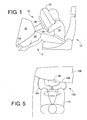
FIGURE 1 is a schematic side view of a vehicle supplemental restraint system including a head/torso protection device and an exemplary lower protection device. An occupant is seated in the driver's seat and each of the protection devices is deployed. -
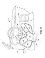
FIGURE 2 is a front perspective view of the exemplary lower protection device ofFIGURE 1 deployed in a vehicle. -
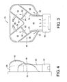
FIGURE 3 is a front view of the exemplary lower protection device ofFIGURE 1 . -
FIGURE 4 is side view of the exemplary lower protection device ofFIGURE 1 . -
FIGURE 5 is a top schematic view of another exemplary lower protection device deployed in a vehicle. -
FIGURE 6 is a front view of yet another exemplary lower protection device. -
FIGURE 7 is a front view of still another exemplary lower protection device. -
FIGURE 8 is a flow chart illustrating a method of inflating a lower protection device for a vehicle. - It should, of course, be understood that the description and drawings herein are merely illustrative and that various modifications and changes can be made in the structures disclosed without departing from the present disclosure. Referring now to the drawings, wherein like numerals refer to like parts throughout the several views,
FIGURES 1 and2 schematically depict an occupant ordriver 10 seated in afront seat 12 of an automotive vehicle V. The vehicle V has installed therein asupplemental restraint system 20 for protecting the front-seat occupant 10 during a vehicle collision. Thesupplemental restraint system 20 includes a known head/torso protection device having apassenger airbag 22 and an exemplary lower protection device having aknee airbag 24. As shown, the head/torso protection device is deployed from asteering wheel 26 attached to asteering column 28. Thesteering column 28 projects from thedashboard 30 located in front of the driver'sseat 12. Theknee airbag 24 is deployed from a lower portion of thedashboard 30. Theairbags - As is known to one skilled in the art, the supplemental
passenger restraint system 20 can include an actuation circuit having a crash sensor, such as, for example, an inertia switch or an accelerometer, and a controller positioned in the vehicle V (neither shown). Upon detection of a crash condition requiring protection of theoccupant 10, as sensed by the crash sensor, the controller directs the actuation circuit to initiate deployment of the head/torso airbag 22 and/or theknee airbag 24. In addition to a vehicle speed, other operational parameters, such as confirmation that theoccupant 10 is using a seatbelt, can be measured or identified to assess whether the head/torso airbag 22 and/or theknee airbag 24 should be deployed. - As is well known, the head/
torso airbag 22 helps prevent contact betweenoccupant 10 and thesteering wheel 26 and/ordashboard 30 during a vehicle collision. The head/torso airbag 22 inflates into the vehicle passenger compartment through a deployment opening (not shown) in thesteering wheel 26. The force needed to open the deployment opening comes from the initial pressurization of head/torso airbag 22 by a gas generator or inflator (not shown). Upon activation, the inflator produces a gas or inflation fluid under pressure and directs the inflation fluid into the head/torso airbag 22. After the head/torso airbag 22 is inflated with sufficient pressure to push open the deployment opening and enable movement of the head/torso airbag 22 through the deployment opening, the head/torso airbag 22 moves into a fully inflated position in the vehicle passenger compartment. - As shown, the
exemplary knee airbag 24 inflates through adeployment opening 40 located in a lower portion of thedashboard 30. Acover 42 is mounted on thedashboard 30 for closing thedeployment opening 40. In its inflated position, theknee airbag 24 covers the lower half of thedashboard 30 and is positioned generally between thedashboard 30 and the leg portions (e.g., the knees and shins) of theoccupant 10 sitting in thefront seat 12. An upper portion of theknee airbag 24 is designed to reach an area near a lower portion of thesteering column 28 in a completely inflated state. Similar to the head/torso airbag 22, the force that is needed to open thedeployment opening 40 comes from the initial pressurization ofknee airbag 24 by a gas generator orinflator 46 that generates a gas under pressure. Theknee airbag 24 is operatively connected to thegas generator 46 for receiving the gas therefrom. The increased pressure causes theknee airbag 24 to inflate outwardly through thedeployment opening 40 into a fully inflated position in the passenger compartment. - With reference to
FIGURES 3 and 4 , theexemplary knee airbag 24 is a multi-chamber knee airbag including a plurality of separate inflation chambers, particularly, at least one first inflation chamber (e.g. chamber 50), at least one second inflation chamber (e.g.,chambers 52, 54), at least one third inflation chamber (e.g.,chambers 56, 58) and at least one fourth inflation chamber (e.g., chamber 60). As shown, themulti-chamber knee airbag 24 of the illustrated embodiment includes a singlefirst inflation chamber 50, a pair of spaced apartsecond inflation chambers third inflation chambers fourth inflation chamber 60. Eachsecond chamber third chambers second chamber 52 is located abovethird chamber 56 andsecond chamber 54 is located abovethird chamber 58. Thefourth chamber 60 is deployed above thefirst chamber 50 and between the pair ofsecond chambers knee airbag 24 is generally defined by the second, third andfourth chambers first chamber 50 is flanked by the stacked second andthird chambers knee airbag 24 has a generally rectangular shape, although alternative shapes are contemplated, and a depth of each of thefirst chamber 50 andfourth chamber 60 is less than a depth of each of thesecond chambers third chambers - To form the
separate inflation chambers knee airbag 24 includes a plurality of internal baffles or panels, particularly, a pair of firstinternal baffles internal baffles internal baffles internal baffles internal baffles FIGURE 3 , the pair of first andsecond baffles inflation chamber 86 which projects from thegas generator 46. The generally Y-shapedinflation chamber 86 at least partially defines or is comprised by thefirst chamber 50 and the two spaced apartsecond chambers first baffle first chamber 50 and one of thesecond chambers third chambers second baffle first chamber 50 and one of thesecond chambers fourth chamber 60. Each thirdinternal baffle first baffles second baffles first chamber 50 from one of thesecond chambers internal baffle 82 spans betweenfirst baffle 72 andsecond baffle 76 for separating thefirst chamber 50 fromsecond chamber 52. Thirdinternal baffle 84 spans betweenfirst baffle 74 andsecond baffle 78 for separating thefirst chamber 50 fromsecond chamber 54. The pair of thirdinternal baffles fourth chamber 60 having a generally V-shape. As a person skilled in the art will understand, the manner of joining the plurality of internal baffles or panels within theexemplary knee airbag 24 is not a limiting feature of theexemplary knee airbag 24. - To effect a sequential expansion of the
inflation chambers knee airbag 24 further includes a plurality of vents orinlet valves first chamber 50 and each of thesecond chambers third chambers second chambers fourth chamber 60. In one embodiment, the plurality ofinternal vents first chamber 50, then thesecond chambers third chambers fourth chamber 60. It is to be appreciated that other sequences could be used and that sequences can overlap (e.g., thethird chambers first chamber 50 before thesecond chambers multi-chamber airbag 24. In the same or another embodiment, the plurality of vents can be configured to cause certain chambers to exhibit increased pressure during impact after theairbag 24 is deployed. For example, thefirst chamber 50 can exhibit a reduced pressure during impact relative to thesecond chambers - More specifically, in the illustrated embodiment, third
internal baffle 82 includesvent 90 for selective communication between thefirst chamber 50 andsecond chamber 52. Thirdinternal baffle 84 includesvent 92 for selective communication between thefirst chamber 50 andsecond chamber 54. Firstinternal baffle 72 includesvent 94 for selective communication between thefirst chamber 50 andthird chamber 56. Firstinternal baffle 74 includesvent 96 for selective communication between thefirst chamber 50 andthird chamber 58. Secondinternal baffle 76 includesvent 100 for selective communication betweensecond chamber 52 and thefourth chamber 60. Finally, secondinternal baffle 78 includesvent 102 for selective communication betweensecond chamber 54 and thefourth chamber 60. - The
vents vents vents vents - In a further example, one or more of the
vents vents vents vents - During a vehicle crash condition, the
gas generator 46 is actuated and gas or inflation fluid is discharged from thegas generator 46 into thefirst inflation chamber 50. Thegas generator 46 is configured to rapidly inflate thefirst inflation chamber 50. In one example, thevents vents first chamber 50 and thesecond chambers chambers fourth chambers vents fourth chambers second chambers - In another example, the
vents second chambers fourth chambers first chamber 50 has reached a second chamber predetermined minimum pressure (e.g., a pressure sufficient to expand the first chamber), the pressureresponsive vents first chamber 50 into each of thesecond chambers - Similarly, when the fluid pressure within the
first chamber 50 has reached a third chamber predetermined minimum pressure, the pressureresponsive vents first chamber 50 into each of thethird chambers second chambers third chambers vents second chambers second chambers fourth chamber 60. It should be appreciated that thegas generator 46 can be configured or sized to create or maintain the respective predetermined minimum pressures of theinflation chambers airbag 24 is being fully expanded. - In the illustrated embodiment, the
separate inflation chambers vents chambers first chamber 50 can be a relatively low pressure chamber that is generally tuned for smaller and less massive occupants, for example, a person with physical characteristics similar to an AF5% crash test dummy, which can be used to model crash behavior of a hypothetical smaller female occupant. AF5% is an abbreviation for "American female 5th percentile" and is generally representative of a person having a height of approximately 152 cm and a mass of approximately 50 kg. - Each
second chamber third chamber second chambers 52, 54) that provides protection for an out of position occupant that has his/her knees spread apart from a center of the seat 12 (i.e., outside a regulated knee impact zone. Finally, thefourth chamber 60 can be configured as a low pressure chamber (similar to the chamber 50) and can be deployed adjacent thesteering column 28 of the vehicle V to prevent contact with the steering column. - During an impact that causes the
airbag 24 to inflate, different pressure characteristics can be exhibited by thechambers first chamber 50, gas can flow back toward the inflator 46 and into the second andthird chambers second chambers third chambers second chambers first chamber 50 is, however, somewhat limited when standard vent holes are used. - For a greater pressure increase in the
second chambers first chamber 50, one way vents could be employed. In one example, one way vents could be used for thevents first chamber 50 to thesecond chambers second chambers first chamber 50. Accordingly, during an impact to thesecond chambers third chamber 60 and is prevented by the one way vents from flowing back into thefirst chamber 50. This increases the pressure seen by the AF50% occupant when impacting thesecond chambers - With reference to
FIGURE 5 , another exemplary leg protection device for a supplemental passenger restraint system is illustrated. Similar to the previous embodiment, the leg protection device includes amulti-chamber knee airbag 150 that inflates through a deployment opening located in a lower portion of aninstrument panel 156. Theknee airbag 150 is operatively connected togas generator 46 for receiving an inflation gas therefrom. When inflated to a deployed position, theknee airbag 150 covers the lower half of theinstrument panel 156 and is positioned generally between theinstrument panel 156 and the leg portions of theoccupant 10 sitting in the driver's seat. As shown, anouter surface 158 of theinstrument panel 156 is oriented at an angle such that one knee of thedriver 10 is positioned closer to theinstrument panel 156 than the other knee of the driver. To ensure that both knees are loaded at the same time during a crash condition, theknee airbag 150 is asymmetric in configuration. Particularly, anouter surface 160 of the knee airbag is angled with respect to theinstrument panel 156 of the vehicle. Internal baffles within theknee airbag 150 control the shape of the separate inflation chambers, which can have different capacities, to account for the shape of theinstrument panel 156. The asymmetric configuration or wedge shape of theknee airbag 150 provides for simultaneous contact to both legs of theoccupant 10 for uniform load distribution. - With reference to
FIGURE 6 , yet another exemplary leg protection device for a supplemental passenger restraint system is illustrated. Similar to the embodiment depicted inFIG. 3 , the leg protection device includes amulti-chamber knee airbag 200 defining afirst inflation chamber 210, a pair of spaced apartsecond inflation chambers third inflation chambers fourth inflation chamber 220. Thefirst chamber 210 has aninlet 230 for directly receiving the gas generated by thegas generator 46. Eachsecond inflation chamber valve first chamber 210. Eachthird inflation chamber valve first chamber 210. Thefourth chamber 220 has a pair of vents orvalves third chambers - Unlike the
airbag 24 ofFIG. 3 , theknee airbag 200 further includes two arm-protectinginflation chambers chamber valve second chambers chamber 250 located on the left side of theknee airbag 200 is inflated so as to cover the left side area of thesteering column 28. Arm-protectingchamber 252 located on the right side of theknee airbag 200 is inflated so as to cover the right side area of thesteering column 28 and an upper portion of a center console panel 260 (FIGURE 2 ). - In case of emergency such as a vehicle collision, the
gas generator 46 is actuated, and theknee airbag 200 is inflated by the gas from the gas generator. The first, second, third andfourth inflation chambers knee airbag 24. In addition, in this exemplary embodiment, gas flows through thesecond chambers chambers vents dashboard 30 and a backside of thesteering wheel 26 to receive the left and right arms of theoccupant 10. This prevents the left and right arms of the passenger from directly striking the vehicle body. Thevents second chambers chambers - With reference to
FIGURE 7 , still another exemplary leg protection device for a supplemental passenger restraint system is illustrated. The illustrated leg protection device includes amulti-chamber knee airbag 300 defining afirst inflation chamber 310, a pair of spaced apartsecond inflation chambers first inflation chamber 310, a V-shapedthird inflation chamber 320 received within anupper recess 310a of the first inflation chamber, and afourth inflation chamber 322 received within anupper recess 320a of thethird inflation chamber 320. Thefirst chamber 310 of this embodiment replaces the first andsecond chambers FIG. 3 embodiment. Thesecond chambers third chambers FIG. 3 and the third andfourth chambers fourth chamber 60 ofFIG. 3 . - The
first chamber 310 has aninlet 330 for directly receiving the gas generated by thegas generator 46. Eachsecond inflation chamber valve first chamber 310. Thethird chamber 320 has a pair of vents orvalves first chamber 310. Thefourth chamber 322 has a pair of vents orvalves 340, 342, each communicating with thethird chamber 320. The vents or valves can be configured to create a desired inflation sequence for the chambers and/or to cause the chambers to exhibit desired pressures during impact in generally same manner as described in reference to the previous embodiments. - More particularly, for example, the
first chamber 310 can be required to fill or inflate first (i.e., prior to filling of the other chambers) to provide initial restraint to an occupant upon deployment of theairbag 300. Next, thesecond chambers first chamber 310 exceeds a second chamber minimum predetermined pressure) to provide protection laterally adjacent both sides of thefirst chamber 310. Next, thethird chamber 320 can be filled or inflated (i.e., after pressure within thefirst chamber 310 exceeds a third chamber minimum predetermined pressure). Thethird chamber 320 can be sized and shaped (and positioned) to overlap a steering column cover and can be used to control a volume of thefirst chamber 310. Lastly, thefourth chamber 322 can be filled or inflated (i.e., after pressure within thethird chamber 320 exceeds a fourth chamber minimum predetermined pressure). Thefourth chamber 322 can be used to provide depth control around the vehicle's steering column, but can be removed when theairbag 300 is employed as a passenger side airbag. - A method of inflating a leg protection device for a vehicle, such as the leg protection device of
FIGURES 1-4 havingmulti-chamber knee airbag 24, will now be described with reference toFIGURE 8 . Thefirst inflation chamber 50 of theknee airbag 24 is first inflated by thegas generator 46 in response to a vehicle crash condition (S300). Thefirst inflation chamber 50 is fluidly connected to a second inflation chamber and a separate third inflation chamber of the multi-chamber airbag 24 (S302). As shown inFIGURE 3 , theairbag 24 includes the pair ofsecond chambers third chambers second inflation chamber fourth inflation chamber 60 of the multi-chamber airbag 24 (S304). Thesecond inflation chamber first inflation chamber 50 exceeds a second chamber predetermined threshold pressure (S306). Thethird inflation chamber first inflation chamber 50 exceeds a third chamber predetermined threshold pressure (S308). Thefourth inflation chamber 60 is inflated only after a fluid pressure in thesecond inflation chamber vents first chamber 50 and each of thesecond chamber third chamber second chamber fourth chamber 60 are provided (S312). The plurality ofvents third chambers fourth chambers - It will be appreciated that various of the above-disclosed and other features and functions, or alternatives thereof, may be desirably combined into many other different systems or applications.
Claims (13)
- An airbag module for a vehicle comprising:a gas generator (46) for generating a gas; anda multi-chamber airbag (24, 200) operatively connected to the gas generator (46) for receiving the gas therefrom, the airbag (24, 200) defining at least one first inflation chamber (50, 210), at least one second inflation chamber (52, 54, 212, 214), at least one third inflation chamber (56, 58, 216, 218) and at least one fourth inflation chamber (60, 220), the airbag (24, 200) including a plurality of internal vents (90, 92, 94, 96, 100, 102, 232, 234, 236, 238, 240, 242) configured to allow selective communication between the at least one first chamber (50, 210) and each of the at least one second chamber (52, 54, 212, 214) and the at least one third chamber (56, 58, 216, 218) and selective communication between the at least one second chamber (52, 54, 212, 214) and the at least one fourth chamber (60, 220), the plurality of internal vents (90, 92, 94, 96, 100, 102, 232, 234, 236, 238, 240, 242) configured to create a higher pressure in one or more selective chambers by restricting an ability of the gas to escape the one or more selective chambers, wherein an order of internal venting between the respective inflation chambers is predetermined so as to control pressure and inflation of the multi-chamber airbag, characterized in thatthe at least one second chamber includes two spaced apart second chambers (52, 54, 212, 214) and the at least one third chamber includes two spaced apart third chambers (56, 58, 216, 218), each second chamber (52, 54, 212, 214) being deployed above one of the third chambers (56, 58, 216, 218), the fourth chamber (60, 220) being deployed between the second chambers (52, 54, 212, 214), wherein the first chamber (50, 210) is substantially surrounded by the second, third and fourth chambers, wherein the airbag includes a pair of first internal baffles (72, 74) and a pair of second internal baffles (76, 78) spaced from the pair of first baffles, the pair of first and second baffles (72, 74, 76, 78) together forming a generally Y-shaped inflation chamber which at least partially defines the first chamber (50, 210) and the two spaced apart second chambers (52, 54, 212, 214), further including a pair of third internal baffles (82, 84), each third baffle spanning between one of the first baffles (72, 74) and one of the second baffles (76, 78) for separating the first chamber (50, 210) from one of the second chambers (52, 54, 212, 214), each third baffle (82, 84) including a vent (90, 92, 232, 234) for selective communication between the first chamber (50, 210) and the second chamber (52, 54, 212, 214), wherein the fourth chamber (60, 220) is at least partially received within an upper recess of the first chamber (50, 210).
- The airbag module of claim 1, wherein a flow of gas from the at least one first chamber (50, 210) into the at least one second chamber (52, 54, 212, 214) is at a higher rate than a flow of gas from the first chamber into the at least one third chamber (56, 58,216,218).
- The airbag module of claim 1 or 2, wherein the airbag module is a leg protection device and the first chamber (50, 210) is a low pressure chamber that is tuned for occupants with physical characteristics similar to an AF5% crash test dummy.
- The airbag module of claim 3, wherein the at least one second chamber (52, 54, 212, 214) is a high pressure chamber that is tuned for occupants with physical characteristics at least similar to an AM50% crash test dummy.
- The airbag module of anyone of claims 1 to 4, wherein the at least one third chamber (56, 58, 216, 218) is a high pressure chamber that is tuned for an out of position occupant to protect knee impacts outside of a regulated knee impact zone.
- The airbag module of anyone of claims 1 to 5, wherein the fourth chamber (60, 220) is configured as a low pressure chamber and is deployed adjacent an associated steering column cover (28) of the vehicle.
- The airbag module of anyone of claims 1 to 6, wherein each first baffle (72, 74) separates the first chamber (50, 210) from one of the second chambers (52, 54, 212, 214), each first baffle including a vent (94, 96, 236, 238) for selective communication between the at least one first chamber and the third chambers (56, 58, 216, 218).
- The airbag module of anyone of claims 1 to 7, wherein the pair of second baffles (76, 78) separates the second chambers (52, 54, 212, 214) from the at least one fourth chamber (60, 220), each second baffle including a vent (100, 102, 240, 242) for selective communication between each second chambers and the at least one fourth chamber.
- The airbag module of anyone of claims 1 to 8, wherein a depth of each of the at least one first chamber (50, 210) and the at least one fourth chamber (60, 220) is less than a depth of each of the at least one second chamber (52, 54, 212, 214) and the at least one third chamber (56, 58, 216, 218).
- The airbag module of anyone of claims 1 to 9, wherein the airbag module is a leg protection device, the airbag (24, 200) being asymmetric in configuration such that an outer surface of the airbag is angled with respect to an associated instrument panel (30) of the vehicle, the asymmetric configuration of the airbag providing for substantially simultaneous contact to both legs of the occupant for uniform load distribution.
- The airbag module of anyone of claims 1 to 10, wherein the airbag module is a leg protection device, the airbag (200) including two arm protecting chambers (250, 252), one on each side of the airbag.
- A method of inflating a leg protection device for a vehicle comprising the steps of:inflating a first inflation chamber (50, 210) of a multi-chamber airbag (24, 200), the first chamber fluidly connected to a pair of second inflation chambers (52, 54, 212, 214) and a pair of separate third inflation chambers (56, 58, 216, 218) of the multi-chamber airbag, the second inflation chambers fluidly connected to a fourth inflation chamber (60, 220) of the multi-chamber airbag;inflating the second inflation chambers (52, 54, 212, 214) only after a fluid pressure in the first inflation chamber (50, 210) exceeds a first predetermined threshold pressure;inflating the third inflation chambers (56, 58, 216, 218) only after a fluid pressure in the first inflation chamber (50, 210) exceeds a second predetermined threshold pressure; andinflating the fourth inflation chamber (60, 220) only after a fluid pressure in the second inflation chambers (52, 54, 212, 214) exceeds a third predetermined threshold pressure.
- The method of claim 12, further comprising providing a plurality of vents (90, 92, 94, 96, 100, 102, 232, 234, 236, 238, 240, 242) configured to allow selective communication between the first chamber (50, 210) and each of the second chamber (52, 54, 212, 214) and third chamber (56, 58, 216, 218) and selective communication between the second chamber and the fourth chamber (60, 220), the plurality of vents being configured to maintain a higher pressure in the second and third chambers relative to the first and fourth chambers by restricting ability of the gas to escape the second and third chambers.
Applications Claiming Priority (2)
| Application Number | Priority Date | Filing Date | Title |
|---|---|---|---|
| US12/688,488 US8376396B2 (en) | 2010-01-15 | 2010-01-15 | Multi-chamber knee airbag |
| PCT/US2011/020012 WO2011087923A1 (en) | 2010-01-15 | 2011-01-03 | Multi-chamber knee airbag |
Publications (3)
| Publication Number | Publication Date |
|---|---|
| EP2523832A1 EP2523832A1 (en) | 2012-11-21 |
| EP2523832A4 EP2523832A4 (en) | 2013-10-09 |
| EP2523832B1 true EP2523832B1 (en) | 2015-04-08 |
Family
ID=44277045
Family Applications (1)
| Application Number | Title | Priority Date | Filing Date |
|---|---|---|---|
| EP11733193.4A Not-in-force EP2523832B1 (en) | 2010-01-15 | 2011-01-03 | Multi-chamber knee airbag |
Country Status (7)
| Country | Link |
|---|---|
| US (1) | US8376396B2 (en) |
| EP (1) | EP2523832B1 (en) |
| JP (1) | JP5511985B2 (en) |
| CN (1) | CN102781733B (en) |
| CA (1) | CA2785932C (en) |
| MX (1) | MX2012008165A (en) |
| WO (1) | WO2011087923A1 (en) |
Families Citing this family (50)
| Publication number | Priority date | Publication date | Assignee | Title |
|---|---|---|---|---|
| US8540278B2 (en) * | 2009-04-30 | 2013-09-24 | Tk Holdings Inc. | Airbag assembly |
| KR101560540B1 (en) | 2012-02-29 | 2015-10-16 | 아우토리브 디벨롭먼트 아베 | Knee airbag module |
| DE102013003239B4 (en) * | 2013-02-27 | 2019-03-21 | Autoliv Development Ab | knee airbag |
| US8851508B1 (en) | 2013-03-15 | 2014-10-07 | Autoliv Asp, Inc. | Delayed vent in airbag curtain |
| US8850623B1 (en) * | 2013-04-06 | 2014-10-07 | Mazz Enterprises, Llc | Helmet with energy management system |
| DE102014106198B4 (en) * | 2013-05-09 | 2017-02-09 | GM Global Technology Operations LLC (n. d. Gesetzen des Staates Delaware) | Airbag arrangement for the vehicle |
| JP5816662B2 (en) | 2013-08-29 | 2015-11-18 | 富士重工業株式会社 | Crew protection device |
| JP5891210B2 (en) * | 2013-08-29 | 2016-03-22 | 富士重工業株式会社 | Crew protection device |
| US9132797B2 (en) | 2013-10-28 | 2015-09-15 | Ford Global Technologies, Llc | Non-symmetrical knee airbag |
| US10889260B2 (en) * | 2014-02-11 | 2021-01-12 | Key Safety Systems, Inc. | Airbag cushion assembly with one-way check valves |
| US9969349B2 (en) | 2014-04-24 | 2018-05-15 | Ford Global Technologies, Llc | Passenger airbag with extended base |
| US9561774B2 (en) * | 2014-04-24 | 2017-02-07 | Ford Global Technologies, Llc | Winged driver airbag |
| US9156422B1 (en) * | 2014-08-18 | 2015-10-13 | Ford Global Technologies, Llc | Active bolster with multiple bladders on single trim piece |
| JP6446908B2 (en) * | 2014-08-20 | 2019-01-09 | Joyson Safety Systems Japan株式会社 | Passenger leg restraining device |
| US9475445B2 (en) * | 2014-08-25 | 2016-10-25 | Ford Global Technologies, Llc | Vehicle airbag appendage |
| JP6237535B2 (en) * | 2014-08-25 | 2017-11-29 | 豊田合成株式会社 | Lower limb protection airbag |
| JP6303935B2 (en) * | 2014-09-08 | 2018-04-04 | 豊田合成株式会社 | Lower limb protection airbag |
| DE102014013649B4 (en) * | 2014-09-19 | 2023-08-10 | Zf Airbag Germany Gmbh | Adaptive, deployable restraint element for a vehicle safety system, gas bag module and vehicle safety system with such a restraint element and use of the fin jet effect in an adaptive restraint system |
| US9614210B2 (en) | 2014-09-30 | 2017-04-04 | Johnson Controls Technology Company | Battery module vent system and method |
| KR101664588B1 (en) * | 2014-11-24 | 2016-10-11 | 현대자동차주식회사 | Passenger air bag apparatus for vehicle |
| KR101647445B1 (en) * | 2014-11-27 | 2016-08-11 | 아우토리브 디벨롭먼트 아베 | Airbag for vehicle |
| JP6383303B2 (en) * | 2015-02-24 | 2018-08-29 | マツダ株式会社 | Airbag device |
| CN105128807B (en) * | 2015-07-21 | 2018-03-16 | 浙江吉利汽车研究院有限公司 | Four limbs protection air bag in car steering room |
| US9731674B2 (en) * | 2015-09-11 | 2017-08-15 | Ford Global Technologies, Llc | Airbag assembly including depressed region below steering column |
| US9623831B1 (en) * | 2015-10-30 | 2017-04-18 | Ford Global Technologies, Llc | Three-chamber frontal impact airbag with controlled pressure differentials |
| US9789844B2 (en) | 2015-11-02 | 2017-10-17 | Ford Global Technologies, Llc | Dual chamber airbag with asymmetrically tunable parameters and method of manufacturing the same |
| US9676363B1 (en) * | 2016-04-15 | 2017-06-13 | Ford Global Technologies, Llc | Multi-chambered airbag with controlled pressure differentials |
| US9663060B1 (en) | 2016-04-15 | 2017-05-30 | Ford Global Technologies, Llc | Multi-chambered airbag with controlled pressure differentials |
| US9676362B1 (en) * | 2016-04-15 | 2017-06-13 | Ford Global Technologies, Llc | Multi-chambered airbag with controlled pressure differentials |
| GB2552145B (en) * | 2016-07-07 | 2018-12-05 | Jaguar Land Rover Ltd | Airbag apparatus |
| GB2552146B (en) * | 2016-07-07 | 2018-12-05 | Jaguar Land Rover Ltd | Airbag apparatus |
| US10029643B2 (en) * | 2016-08-22 | 2018-07-24 | Ford Global Technologies, Llc | Airbag including a plurality of fingers extending from an impact surface |
| US9956937B2 (en) * | 2016-09-07 | 2018-05-01 | Ford Global Technologies, Llc | Airbag with at least one extension |
| US10343641B2 (en) * | 2017-04-17 | 2019-07-09 | Ford Global Technologies, Llc | Vehicle airbag |
| US10457243B2 (en) * | 2017-06-01 | 2019-10-29 | Autoliv Asp, Inc. | Knee airbag assemblies |
| US10589705B2 (en) * | 2017-08-01 | 2020-03-17 | Ford Global Technologies, Llc | Restraint system |
| EP3594070B1 (en) * | 2018-07-13 | 2021-01-13 | Volvo Car Corporation | Knee airbag arrangement comprising external tether |
| EP3594072B1 (en) * | 2018-07-13 | 2020-12-09 | Volvo Car Corporation | Knee airbag arrangement |
| DE102018215200A1 (en) * | 2018-09-07 | 2020-03-12 | Bayerische Motoren Werke Aktiengesellschaft | Knee airbag arrangement, vehicle with a knee airbag arrangement and method for deploying a knee airbag arrangement |
| CN109109810A (en) * | 2018-09-26 | 2019-01-01 | 北京长城华冠汽车技术开发有限公司 | Knee protective device, seat and vehicle |
| DE102019101284A1 (en) * | 2019-01-18 | 2020-07-23 | Trw Automotive Gmbh | Knee gas bag module |
| US10974684B2 (en) * | 2019-03-01 | 2021-04-13 | Autoliv Asp, Inc. | Multi-chambered driver-side airbag assemblies |
| DE102019208417A1 (en) * | 2019-06-11 | 2020-12-17 | Audi Ag | Leg protection device for an occupant protection system of a vehicle |
| DE102019117216A1 (en) * | 2019-06-26 | 2020-12-31 | Autoliv Development Ab | Knee airbag, knee airbag module and steering arrangement |
| US11623603B2 (en) * | 2021-04-26 | 2023-04-11 | Ford Global Technologies, Llc | Vehicle front airbag assembly with multiple chambers |
| US11685328B2 (en) * | 2021-04-29 | 2023-06-27 | Ford Global Technologies, Llc | Airbag having multiple inflation chambers supported on a dash |
| DE102021112697A1 (en) * | 2021-05-17 | 2022-11-17 | Zf Automotive Germany Gmbh | Vehicle occupant restraint system with a passenger airbag |
| US11975674B2 (en) * | 2021-12-17 | 2024-05-07 | Waymo Llc | Airbag systems for autonomous vehicles |
| US12447921B1 (en) | 2024-09-16 | 2025-10-21 | Ford Global Technologies, Llc | Seat bottom mounted airbag assembly |
| US20260091755A1 (en) * | 2024-09-30 | 2026-04-02 | Hyundai Mobis Co., Ltd. | Passenger airbag |
Family Cites Families (35)
| Publication number | Priority date | Publication date | Assignee | Title |
|---|---|---|---|---|
| US3768830A (en) | 1970-09-23 | 1973-10-30 | Eaton Corp | Vehicle knee bag |
| US3747952A (en) * | 1971-09-17 | 1973-07-24 | R Graebe | Protective device |
| US3752501A (en) * | 1971-10-20 | 1973-08-14 | Ford Motor Co | Steering wheel inflatable cushion device |
| US4290627A (en) * | 1979-12-03 | 1981-09-22 | General Motors Corporation | L-shaped inflatable restraint cushion |
| US5458366A (en) | 1994-06-01 | 1995-10-17 | Morton International, Inc. | Compartmentalized airbag knee bolster |
| JP3316315B2 (en) * | 1994-09-06 | 2002-08-19 | タカタ株式会社 | Airbag device for passenger seat |
| EP0849129B1 (en) * | 1996-12-21 | 2004-06-16 | Volkswagen Aktiengesellschaft | Side air bag system for a motor vehicle |
| DE29807424U1 (en) * | 1998-04-23 | 1998-08-27 | Trw Repa Gmbh | Knee protection device for vehicle occupants |
| DE19824601C2 (en) | 1998-06-02 | 2003-04-03 | Breed Automotive Tech | Air bag with compensation volume |
| US6086092A (en) * | 1998-07-07 | 2000-07-11 | Trw Vehicle Safety Systems Inc. | Inflatable vehicle occupant protection device |
| DE19932696C1 (en) * | 1999-07-15 | 2000-09-07 | Daimler Chrysler Ag | Occupant protection device with at least two airbags for filling with gas has first airbag with short unfolding length towards occupant triggered independently of second airbag, esp. earlier |
| JP3912144B2 (en) * | 2001-05-21 | 2007-05-09 | タカタ株式会社 | Passenger leg protection device for passenger seat |
| JP2003034208A (en) * | 2001-07-24 | 2003-02-04 | Takata Corp | Airbag |
| JP3687602B2 (en) * | 2001-12-10 | 2005-08-24 | トヨタ自動車株式会社 | Vehicle occupant knee protection device |
| JP2003182500A (en) * | 2001-12-25 | 2003-07-03 | Takata Corp | Occupant protection device |
| JP3948332B2 (en) * | 2002-04-15 | 2007-07-25 | タカタ株式会社 | Crew protection device |
| US7648158B2 (en) * | 2003-04-03 | 2010-01-19 | Takata Corporation | Twin airbag |
| JP4321228B2 (en) * | 2003-11-14 | 2009-08-26 | タカタ株式会社 | Air bag and air bag device |
| US7316415B2 (en) * | 2004-08-30 | 2008-01-08 | Autoliv Asp, Inc. | Dual chamber airbag |
| JP4244896B2 (en) | 2004-09-22 | 2009-03-25 | トヨタ自動車株式会社 | Airbag device |
| JP2007203937A (en) * | 2006-02-03 | 2007-08-16 | Toyoda Gosei Co Ltd | Knee protecting airbag device |
| JP2007216724A (en) * | 2006-02-14 | 2007-08-30 | Autoliv Development Ab | Airbag device |
| DE102006008756A1 (en) * | 2006-02-24 | 2007-09-06 | Ford Global Technologies, LLC, Dearborn | knee airbag |
| US7448645B2 (en) * | 2006-03-31 | 2008-11-11 | Ford Global Technologies, Llc | Contoured side impact airbag |
| FR2900111B1 (en) * | 2006-04-24 | 2011-02-11 | Trw Automotive Gmbh | VEHICLE OCCUPANT RETENTION DEVICE WITH GAS CUSHION. |
| US7347445B2 (en) * | 2006-05-12 | 2008-03-25 | Hyundai Motor Company | Vehicle airbag device with an auxiliary chamber |
| US7758069B2 (en) * | 2006-05-18 | 2010-07-20 | Autoliv Asp, Inc. | Knee airbag and restraint system for suppressing deployment of head/torso airbag |
| US20080036189A1 (en) * | 2006-07-14 | 2008-02-14 | Takata Corporation | Airbag |
| JP2008044594A (en) | 2006-07-19 | 2008-02-28 | Toyoda Gosei Co Ltd | Airbag device |
| JP2008120106A (en) | 2006-11-08 | 2008-05-29 | Toyota Motor Corp | Knee airbag device for vehicle |
| JP4231520B2 (en) * | 2006-11-24 | 2009-03-04 | トヨタ自動車株式会社 | Knee airbag device with column |
| EP2008879B1 (en) | 2007-06-29 | 2012-06-27 | Dalphi Metal España, S.A. | Three-chamber adaptive side airbag |
| EP2072348B1 (en) * | 2007-12-18 | 2016-10-05 | Autoliv Development AB | Knee airbag and method of folding the same |
| US8596678B2 (en) * | 2009-10-05 | 2013-12-03 | Autoliv Asp, Inc. | Air bag with pressure-managed gas delivery inflatable duct |
| DE102012008604A1 (en) * | 2012-04-27 | 2012-11-29 | Daimler Ag | Occupant protection device for car, has airbag including central chamber, two outer lower chambers and two outer upper chambers, where chambers are filled with air such that chambers have different internal pressure |
-
2010
- 2010-01-15 US US12/688,488 patent/US8376396B2/en not_active Expired - Fee Related
-
2011
- 2011-01-03 EP EP11733193.4A patent/EP2523832B1/en not_active Not-in-force
- 2011-01-03 CN CN201180012641.3A patent/CN102781733B/en not_active Expired - Fee Related
- 2011-01-03 JP JP2012548963A patent/JP5511985B2/en not_active Expired - Fee Related
- 2011-01-03 MX MX2012008165A patent/MX2012008165A/en active IP Right Grant
- 2011-01-03 WO PCT/US2011/020012 patent/WO2011087923A1/en not_active Ceased
- 2011-01-03 CA CA2785932A patent/CA2785932C/en not_active Expired - Fee Related
Also Published As
| Publication number | Publication date |
|---|---|
| CA2785932C (en) | 2014-07-08 |
| CA2785932A1 (en) | 2011-07-21 |
| WO2011087923A1 (en) | 2011-07-21 |
| MX2012008165A (en) | 2012-08-03 |
| US8376396B2 (en) | 2013-02-19 |
| EP2523832A1 (en) | 2012-11-21 |
| US20110175334A1 (en) | 2011-07-21 |
| JP2013517173A (en) | 2013-05-16 |
| CN102781733A (en) | 2012-11-14 |
| JP5511985B2 (en) | 2014-06-04 |
| EP2523832A4 (en) | 2013-10-09 |
| CN102781733B (en) | 2014-01-22 |
Similar Documents
| Publication | Publication Date | Title |
|---|---|---|
| CA2785932C (en) | Multi-chamber knee airbag | |
| US8590928B2 (en) | Knee airbag with passive venting for out of position occupant protection | |
| EP2021211B1 (en) | Active venting inflator device | |
| CN106627470B (en) | Three-cavity frontal collision safety air bag with controllable pressure difference | |
| US8480124B2 (en) | Seat bolster chamber | |
| US10166945B2 (en) | Far side airbag device for vehicle | |
| US20180065581A1 (en) | Vehicle front passenger seat airbag device | |
| JP2017537025A (en) | Airbag module | |
| CN110116700B (en) | Side airbag device | |
| JPH06227348A (en) | Side airbag device | |
| EP3105088B1 (en) | Airbag cushion assembly with one-way check valves | |
| CN114763120A (en) | Occupant restraint system | |
| KR20180112033A (en) | Side air bag with internal diffuser | |
| US20220306038A1 (en) | Airbag with passive and active vents | |
| WO2016105519A1 (en) | Side impact airbag module | |
| KR102182901B1 (en) | Passenger Airbag Apparatus | |
| JP2007050848A (en) | Airbag device | |
| JP5549577B2 (en) | Side airbag device for rear seats | |
| JP2010247661A (en) | Crew protection device | |
| US7475905B2 (en) | Airbag module | |
| KR100803624B1 (en) | Side airbag | |
| JP7858821B2 (en) | Vehicle side airbag system | |
| CN107010000B (en) | Active pad stress relief exhaust for fail-safe weld protection | |
| US20260125024A1 (en) | Tether protection panel for airbag module | |
| KR20100099550A (en) | Passenger air-bag for a vehicle |
Legal Events
| Date | Code | Title | Description |
|---|---|---|---|
| PUAI | Public reference made under article 153(3) epc to a published international application that has entered the european phase |
Free format text: ORIGINAL CODE: 0009012 |
|
| 17P | Request for examination filed |
Effective date: 20120713 |
|
| AK | Designated contracting states |
Kind code of ref document: A1 Designated state(s): AL AT BE BG CH CY CZ DE DK EE ES FI FR GB GR HR HU IE IS IT LI LT LU LV MC MK MT NL NO PL PT RO RS SE SI SK SM TR |
|
| DAX | Request for extension of the european patent (deleted) | ||
| A4 | Supplementary search report drawn up and despatched |
Effective date: 20130910 |
|
| RIC1 | Information provided on ipc code assigned before grant |
Ipc: B60R 21/233 20060101AFI20130904BHEP |
|
| 17Q | First examination report despatched |
Effective date: 20140610 |
|
| GRAP | Despatch of communication of intention to grant a patent |
Free format text: ORIGINAL CODE: EPIDOSNIGR1 |
|
| INTG | Intention to grant announced |
Effective date: 20141027 |
|
| GRAS | Grant fee paid |
Free format text: ORIGINAL CODE: EPIDOSNIGR3 |
|
| GRAA | (expected) grant |
Free format text: ORIGINAL CODE: 0009210 |
|
| AK | Designated contracting states |
Kind code of ref document: B1 Designated state(s): AL AT BE BG CH CY CZ DE DK EE ES FI FR GB GR HR HU IE IS IT LI LT LU LV MC MK MT NL NO PL PT RO RS SE SI SK SM TR |
|
| REG | Reference to a national code |
Ref country code: GB Ref legal event code: FG4D |
|
| REG | Reference to a national code |
Ref country code: CH Ref legal event code: EP |
|
| REG | Reference to a national code |
Ref country code: IE Ref legal event code: FG4D |
|
| REG | Reference to a national code |
Ref country code: AT Ref legal event code: REF Ref document number: 720299 Country of ref document: AT Kind code of ref document: T Effective date: 20150515 |
|
| REG | Reference to a national code |
Ref country code: DE Ref legal event code: R096 Ref document number: 602011015476 Country of ref document: DE Effective date: 20150521 |
|
| REG | Reference to a national code |
Ref country code: AT Ref legal event code: MK05 Ref document number: 720299 Country of ref document: AT Kind code of ref document: T Effective date: 20150408 |
|
| REG | Reference to a national code |
Ref country code: NL Ref legal event code: VDEP Effective date: 20150408 |
|
| REG | Reference to a national code |
Ref country code: LT Ref legal event code: MG4D |
|
| PG25 | Lapsed in a contracting state [announced via postgrant information from national office to epo] |
Ref country code: NL Free format text: LAPSE BECAUSE OF FAILURE TO SUBMIT A TRANSLATION OF THE DESCRIPTION OR TO PAY THE FEE WITHIN THE PRESCRIBED TIME-LIMIT Effective date: 20150408 |
|
| PG25 | Lapsed in a contracting state [announced via postgrant information from national office to epo] |
Ref country code: HR Free format text: LAPSE BECAUSE OF FAILURE TO SUBMIT A TRANSLATION OF THE DESCRIPTION OR TO PAY THE FEE WITHIN THE PRESCRIBED TIME-LIMIT Effective date: 20150408 Ref country code: LT Free format text: LAPSE BECAUSE OF FAILURE TO SUBMIT A TRANSLATION OF THE DESCRIPTION OR TO PAY THE FEE WITHIN THE PRESCRIBED TIME-LIMIT Effective date: 20150408 Ref country code: NO Free format text: LAPSE BECAUSE OF FAILURE TO SUBMIT A TRANSLATION OF THE DESCRIPTION OR TO PAY THE FEE WITHIN THE PRESCRIBED TIME-LIMIT Effective date: 20150708 Ref country code: ES Free format text: LAPSE BECAUSE OF FAILURE TO SUBMIT A TRANSLATION OF THE DESCRIPTION OR TO PAY THE FEE WITHIN THE PRESCRIBED TIME-LIMIT Effective date: 20150408 Ref country code: PT Free format text: LAPSE BECAUSE OF FAILURE TO SUBMIT A TRANSLATION OF THE DESCRIPTION OR TO PAY THE FEE WITHIN THE PRESCRIBED TIME-LIMIT Effective date: 20150810 Ref country code: FI Free format text: LAPSE BECAUSE OF FAILURE TO SUBMIT A TRANSLATION OF THE DESCRIPTION OR TO PAY THE FEE WITHIN THE PRESCRIBED TIME-LIMIT Effective date: 20150408 |
|
| PG25 | Lapsed in a contracting state [announced via postgrant information from national office to epo] |
Ref country code: LV Free format text: LAPSE BECAUSE OF FAILURE TO SUBMIT A TRANSLATION OF THE DESCRIPTION OR TO PAY THE FEE WITHIN THE PRESCRIBED TIME-LIMIT Effective date: 20150408 Ref country code: AT Free format text: LAPSE BECAUSE OF FAILURE TO SUBMIT A TRANSLATION OF THE DESCRIPTION OR TO PAY THE FEE WITHIN THE PRESCRIBED TIME-LIMIT Effective date: 20150408 Ref country code: IS Free format text: LAPSE BECAUSE OF FAILURE TO SUBMIT A TRANSLATION OF THE DESCRIPTION OR TO PAY THE FEE WITHIN THE PRESCRIBED TIME-LIMIT Effective date: 20150808 Ref country code: RS Free format text: LAPSE BECAUSE OF FAILURE TO SUBMIT A TRANSLATION OF THE DESCRIPTION OR TO PAY THE FEE WITHIN THE PRESCRIBED TIME-LIMIT Effective date: 20150408 Ref country code: GR Free format text: LAPSE BECAUSE OF FAILURE TO SUBMIT A TRANSLATION OF THE DESCRIPTION OR TO PAY THE FEE WITHIN THE PRESCRIBED TIME-LIMIT Effective date: 20150709 |
|
| REG | Reference to a national code |
Ref country code: DE Ref legal event code: R097 Ref document number: 602011015476 Country of ref document: DE |
|
| PG25 | Lapsed in a contracting state [announced via postgrant information from national office to epo] |
Ref country code: EE Free format text: LAPSE BECAUSE OF FAILURE TO SUBMIT A TRANSLATION OF THE DESCRIPTION OR TO PAY THE FEE WITHIN THE PRESCRIBED TIME-LIMIT Effective date: 20150408 Ref country code: DK Free format text: LAPSE BECAUSE OF FAILURE TO SUBMIT A TRANSLATION OF THE DESCRIPTION OR TO PAY THE FEE WITHIN THE PRESCRIBED TIME-LIMIT Effective date: 20150408 |
|
| PLBE | No opposition filed within time limit |
Free format text: ORIGINAL CODE: 0009261 |
|
| STAA | Information on the status of an ep patent application or granted ep patent |
Free format text: STATUS: NO OPPOSITION FILED WITHIN TIME LIMIT |
|
| PG25 | Lapsed in a contracting state [announced via postgrant information from national office to epo] |
Ref country code: CZ Free format text: LAPSE BECAUSE OF FAILURE TO SUBMIT A TRANSLATION OF THE DESCRIPTION OR TO PAY THE FEE WITHIN THE PRESCRIBED TIME-LIMIT Effective date: 20150408 Ref country code: PL Free format text: LAPSE BECAUSE OF FAILURE TO SUBMIT A TRANSLATION OF THE DESCRIPTION OR TO PAY THE FEE WITHIN THE PRESCRIBED TIME-LIMIT Effective date: 20150408 Ref country code: SK Free format text: LAPSE BECAUSE OF FAILURE TO SUBMIT A TRANSLATION OF THE DESCRIPTION OR TO PAY THE FEE WITHIN THE PRESCRIBED TIME-LIMIT Effective date: 20150408 Ref country code: RO Free format text: LAPSE BECAUSE OF NON-PAYMENT OF DUE FEES Effective date: 20150408 |
|
| 26N | No opposition filed |
Effective date: 20160111 |
|
| PG25 | Lapsed in a contracting state [announced via postgrant information from national office to epo] |
Ref country code: IT Free format text: LAPSE BECAUSE OF FAILURE TO SUBMIT A TRANSLATION OF THE DESCRIPTION OR TO PAY THE FEE WITHIN THE PRESCRIBED TIME-LIMIT Effective date: 20150408 |
|
| PG25 | Lapsed in a contracting state [announced via postgrant information from national office to epo] |
Ref country code: BE Free format text: LAPSE BECAUSE OF NON-PAYMENT OF DUE FEES Effective date: 20160131 Ref country code: SI Free format text: LAPSE BECAUSE OF FAILURE TO SUBMIT A TRANSLATION OF THE DESCRIPTION OR TO PAY THE FEE WITHIN THE PRESCRIBED TIME-LIMIT Effective date: 20150408 |
|
| PG25 | Lapsed in a contracting state [announced via postgrant information from national office to epo] |
Ref country code: BE Free format text: LAPSE BECAUSE OF FAILURE TO SUBMIT A TRANSLATION OF THE DESCRIPTION OR TO PAY THE FEE WITHIN THE PRESCRIBED TIME-LIMIT Effective date: 20150408 Ref country code: LU Free format text: LAPSE BECAUSE OF FAILURE TO SUBMIT A TRANSLATION OF THE DESCRIPTION OR TO PAY THE FEE WITHIN THE PRESCRIBED TIME-LIMIT Effective date: 20160103 |
|
| REG | Reference to a national code |
Ref country code: CH Ref legal event code: PL |
|
| GBPC | Gb: european patent ceased through non-payment of renewal fee |
Effective date: 20160103 |
|
| PG25 | Lapsed in a contracting state [announced via postgrant information from national office to epo] |
Ref country code: MC Free format text: LAPSE BECAUSE OF FAILURE TO SUBMIT A TRANSLATION OF THE DESCRIPTION OR TO PAY THE FEE WITHIN THE PRESCRIBED TIME-LIMIT Effective date: 20150408 |
|
| REG | Reference to a national code |
Ref country code: FR Ref legal event code: ST Effective date: 20160930 |
|
| PG25 | Lapsed in a contracting state [announced via postgrant information from national office to epo] |
Ref country code: LI Free format text: LAPSE BECAUSE OF NON-PAYMENT OF DUE FEES Effective date: 20160131 Ref country code: GB Free format text: LAPSE BECAUSE OF NON-PAYMENT OF DUE FEES Effective date: 20160103 Ref country code: CH Free format text: LAPSE BECAUSE OF NON-PAYMENT OF DUE FEES Effective date: 20160131 |
|
| REG | Reference to a national code |
Ref country code: IE Ref legal event code: MM4A |
|
| PG25 | Lapsed in a contracting state [announced via postgrant information from national office to epo] |
Ref country code: FR Free format text: LAPSE BECAUSE OF NON-PAYMENT OF DUE FEES Effective date: 20160201 |
|
| PG25 | Lapsed in a contracting state [announced via postgrant information from national office to epo] |
Ref country code: IE Free format text: LAPSE BECAUSE OF NON-PAYMENT OF DUE FEES Effective date: 20160103 |
|
| PG25 | Lapsed in a contracting state [announced via postgrant information from national office to epo] |
Ref country code: SE Free format text: LAPSE BECAUSE OF FAILURE TO SUBMIT A TRANSLATION OF THE DESCRIPTION OR TO PAY THE FEE WITHIN THE PRESCRIBED TIME-LIMIT Effective date: 20150408 |
|
| PG25 | Lapsed in a contracting state [announced via postgrant information from national office to epo] |
Ref country code: MT Free format text: LAPSE BECAUSE OF FAILURE TO SUBMIT A TRANSLATION OF THE DESCRIPTION OR TO PAY THE FEE WITHIN THE PRESCRIBED TIME-LIMIT Effective date: 20150408 |
|
| PG25 | Lapsed in a contracting state [announced via postgrant information from national office to epo] |
Ref country code: HU Free format text: LAPSE BECAUSE OF FAILURE TO SUBMIT A TRANSLATION OF THE DESCRIPTION OR TO PAY THE FEE WITHIN THE PRESCRIBED TIME-LIMIT; INVALID AB INITIO Effective date: 20110103 Ref country code: CY Free format text: LAPSE BECAUSE OF FAILURE TO SUBMIT A TRANSLATION OF THE DESCRIPTION OR TO PAY THE FEE WITHIN THE PRESCRIBED TIME-LIMIT Effective date: 20150408 Ref country code: SM Free format text: LAPSE BECAUSE OF FAILURE TO SUBMIT A TRANSLATION OF THE DESCRIPTION OR TO PAY THE FEE WITHIN THE PRESCRIBED TIME-LIMIT Effective date: 20150408 |
|
| PG25 | Lapsed in a contracting state [announced via postgrant information from national office to epo] |
Ref country code: MK Free format text: LAPSE BECAUSE OF FAILURE TO SUBMIT A TRANSLATION OF THE DESCRIPTION OR TO PAY THE FEE WITHIN THE PRESCRIBED TIME-LIMIT Effective date: 20150408 Ref country code: TR Free format text: LAPSE BECAUSE OF FAILURE TO SUBMIT A TRANSLATION OF THE DESCRIPTION OR TO PAY THE FEE WITHIN THE PRESCRIBED TIME-LIMIT Effective date: 20150408 Ref country code: MT Free format text: LAPSE BECAUSE OF FAILURE TO SUBMIT A TRANSLATION OF THE DESCRIPTION OR TO PAY THE FEE WITHIN THE PRESCRIBED TIME-LIMIT Effective date: 20160131 |
|
| PG25 | Lapsed in a contracting state [announced via postgrant information from national office to epo] |
Ref country code: BG Free format text: LAPSE BECAUSE OF FAILURE TO SUBMIT A TRANSLATION OF THE DESCRIPTION OR TO PAY THE FEE WITHIN THE PRESCRIBED TIME-LIMIT Effective date: 20150408 |
|
| PG25 | Lapsed in a contracting state [announced via postgrant information from national office to epo] |
Ref country code: AL Free format text: LAPSE BECAUSE OF FAILURE TO SUBMIT A TRANSLATION OF THE DESCRIPTION OR TO PAY THE FEE WITHIN THE PRESCRIBED TIME-LIMIT Effective date: 20150408 |
|
| PGFP | Annual fee paid to national office [announced via postgrant information from national office to epo] |
Ref country code: DE Payment date: 20211130 Year of fee payment: 12 |
|
| REG | Reference to a national code |
Ref country code: DE Ref legal event code: R119 Ref document number: 602011015476 Country of ref document: DE |
|
| PG25 | Lapsed in a contracting state [announced via postgrant information from national office to epo] |
Ref country code: DE Free format text: LAPSE BECAUSE OF NON-PAYMENT OF DUE FEES Effective date: 20230801 |