EP2523512A1 - Mobile communication system, radio base station and mobile station - Google Patents
Mobile communication system, radio base station and mobile station Download PDFInfo
- Publication number
- EP2523512A1 EP2523512A1 EP11731863A EP11731863A EP2523512A1 EP 2523512 A1 EP2523512 A1 EP 2523512A1 EP 11731863 A EP11731863 A EP 11731863A EP 11731863 A EP11731863 A EP 11731863A EP 2523512 A1 EP2523512 A1 EP 2523512A1
- Authority
- EP
- European Patent Office
- Prior art keywords
- state
- carrier
- carriers
- mobile station
- radio base
- Prior art date
- Legal status (The legal status is an assumption and is not a legal conclusion. Google has not performed a legal analysis and makes no representation as to the accuracy of the status listed.)
- Granted
Links
Images


Classifications
-
- H—ELECTRICITY
- H04—ELECTRIC COMMUNICATION TECHNIQUE
- H04L—TRANSMISSION OF DIGITAL INFORMATION, e.g. TELEGRAPHIC COMMUNICATION
- H04L5/00—Arrangements affording multiple use of the transmission path
- H04L5/0001—Arrangements for dividing the transmission path
- H04L5/0003—Two-dimensional division
- H04L5/0005—Time-frequency
- H04L5/0007—Time-frequency the frequencies being orthogonal, e.g. OFDM(A) or DMT
- H04L5/001—Time-frequency the frequencies being orthogonal, e.g. OFDM(A) or DMT the frequencies being arranged in component carriers
-
- H—ELECTRICITY
- H04—ELECTRIC COMMUNICATION TECHNIQUE
- H04W—WIRELESS COMMUNICATION NETWORKS
- H04W56/00—Synchronisation arrangements
- H04W56/004—Synchronisation arrangements compensating for timing error of reception due to propagation delay
- H04W56/0045—Synchronisation arrangements compensating for timing error of reception due to propagation delay compensating for timing error by altering transmission time
-
- H—ELECTRICITY
- H04—ELECTRIC COMMUNICATION TECHNIQUE
- H04W—WIRELESS COMMUNICATION NETWORKS
- H04W72/00—Local resource management
- H04W72/04—Wireless resource allocation
-
- H—ELECTRICITY
- H04—ELECTRIC COMMUNICATION TECHNIQUE
- H04W—WIRELESS COMMUNICATION NETWORKS
- H04W72/00—Local resource management
- H04W72/04—Wireless resource allocation
- H04W72/044—Wireless resource allocation based on the type of the allocated resource
- H04W72/0453—Resources in frequency domain, e.g. a carrier in FDMA
-
- H—ELECTRICITY
- H04—ELECTRIC COMMUNICATION TECHNIQUE
- H04W—WIRELESS COMMUNICATION NETWORKS
- H04W72/00—Local resource management
- H04W72/20—Control channels or signalling for resource management
- H04W72/21—Control channels or signalling for resource management in the uplink direction of a wireless link, i.e. towards the network
-
- H—ELECTRICITY
- H04—ELECTRIC COMMUNICATION TECHNIQUE
- H04W—WIRELESS COMMUNICATION NETWORKS
- H04W74/00—Wireless channel access
- H04W74/08—Non-scheduled access, e.g. ALOHA
- H04W74/0833—Random access procedures, e.g. with 4-step access
-
- H—ELECTRICITY
- H04—ELECTRIC COMMUNICATION TECHNIQUE
- H04W—WIRELESS COMMUNICATION NETWORKS
- H04W88/00—Devices specially adapted for wireless communication networks, e.g. terminals, base stations or access point devices
- H04W88/02—Terminal devices
-
- H—ELECTRICITY
- H04—ELECTRIC COMMUNICATION TECHNIQUE
- H04W—WIRELESS COMMUNICATION NETWORKS
- H04W72/00—Local resource management
Definitions
- the present invention relates to a mobile communication system, a radio base station, and a mobile station.
- CA Carrier Aggregation
- the mobile station UE When the CA is performed in a mobile station UE, the mobile station UE is configured to transmit an uplink signal by using a plurality of "Component Carriers (CCs)" of different frequency bands, to a radio base station eNB.
- CCs Component Carriers
- a problem was that as shown in Fig. 1 , when CA is performed in a mobile station UE by using "Component Carriers (for example, CC #1 and CC #11)" in cells having a different coverage (for example, a cell #1 and a cell #11), and as shown in Fig. 2 , when CA is performed in a mobile station UE by using a "Component Carrier (for example, CC #1)" in a cell #1 in which a repeater is not used, and a “Component Carrier (for example, CC #2)” in a cell #2 in which a repeater #2 is used, the reception timing of an uplink signal in the radio base station eNB varies dramatically in each "Component Carrier".
- the present invention has been achieved in view of the above problem, and an object thereof is to provide a mobile communication system, a radio base station, and a mobile station by which the reception timing of an uplink signal in a radio base station eNB can be maintained within a constant range even when CA is performed.
- a first characteristic of the present embodiment is summarized in that a mobile communication system having a mobile station configured to transmit an uplink signal to a radio base station by using a plurality of carriers having different carrier frequencies, comprising, a timer management unit configured to manage the timer corresponding to the plurality of carriers, and a state management unit configured to manage the state of the plurality of carriers, in which the state management unit is configured to set the state of a carrier, whose timer has expired, to an asynchronous state.
- a second characteristic of the present embodiment is summarized in that a radio base station configured to receive an uplink signal from a mobile station by using a plurality of carriers having different carrier frequencies, comprising, a timer management unit configured to manage the timer corresponding to the plurality of carriers, and a state management unit configured to manage the state of the plurality of carriers, in which the state management unit is configured to set the state of a carrier, whose timer has expired, to an asynchronous state.
- a third characteristic of the present embodiment is summarized in that a mobile station configured to transmit an uplink signal to a radio base station by using a plurality of carriers having different carrier frequencies, comprising, a timer management unit configured to manage the timer corresponding to the plurality of carriers, and a state management unit configured to manage the state of the plurality of carriers, in which the state management unit is configured to set the state of a carrier, whose timer has expired, to an asynchronous state.
- the present invention it is possible to provide a mobile communication system, a radio base station, and a mobile station by which the reception timing of an uplink signal in a radio base station eNB can be maintained within a constant range even when CA is performed.
- the mobile communication system according to the present embodiment is a mobile communication system of the LTE-Advanced scheme, and is configured to enable CA by a mobile station UE.
- the mobile communication system according to the present embodiment may have a configuration as shown in Fig. 1 , or a configuration as shown in Fig. 2 , or any other configuration.
- a cell #1, a cell #2, and a cell #3 are provided as macro cells, and a cell #11, a cell #12, a cell #21, a cell #31, and a cell #32 are provided as flared cells subordinate to a radio base station eNB.
- the cell #11 and the cell #12 are provided within the coverage of the cell #1
- the cell #21 is provided within the coverage of the cell #2
- the cell #31 and the cell #32 are provided within the coverage of the cell #3.
- CC (Component Carrier) #1 is used in the cell #1
- CC #2 is used in the cell #2
- CC #3 is used in the cell #3
- CC #11 is used in the cell #11
- CC #12 is used in the cell #12
- CC #21 is used in the cell #21
- CC #31 is used in the cell #31
- CC #32 is used in the cell #32.
- the CC #1, the CC#2, and the CC #3 are "Component Carriers” having a carrier frequency in the 2-GHz band
- the CC#11, the CC #12, the CC #21, the CC #31, and the CC #32 may be "Component Carriers” having a carrier frequency in the 3.5-GHz band.
- the bandwidth of the "Component Carriers" may be any one of 6 RB (Resource Blocks), 1.5 RB, 25 RB, 50 RB, 75 RB, or 100 RB. Note that 1 RB equals 180 kHz.
- a cell #1 and a cell #2 are provided as macro cells subordinate to the radio base station eNB.
- the CC #1 is used in the cell #1, and the CC #2 is used in the cell #2.
- both the CC #1 and the CC #2 may be "Component Carriers” having a carrier frequency in the 2-GHz band (or 3.5-GHz band).
- the CC #1 may be a "Component Carrier” having a carrier frequency in the 2-GHz band (or 3.5-GHz band)
- the CC #2 may be a "Component Carrier” having a carrier frequency in the 3.5-GHz band (or 2-GHz band).
- a repeater that is, booster
- a repeater #2 is installed in the cell #2.
- the radio base station eNB includes a reception unit 11, a transmission unit 12, a TA timer management unit 13, and a state management unit 14.
- the reception unit 11 is configured to receive an uplink data signal or an uplink control signal transmitted from a mobile station UE by using PUSCH (Physical Uplink Shared Channel) or PUSSCH (Physical Uplink Control Channel) in a plurality of "Components Carriers" having different carrier frequencies.
- PUSCH Physical Uplink Shared Channel
- PUSSCH Physical Uplink Control Channel
- the TA timer management unit 13 is configured to manage a TA (Timing Advande, transmission timing adjustment information) timer corresponding to each CC used in each mobile station UE in which CA is performed.
- TA Transmission Advande, transmission timing adjustment information
- the TA timer management unit 13 is configured to start the TA timer corresponding to each CC, when each CC is in a synchronous state.
- the TA. timer management unit 13 is configured to start the TA timer corresponding to CC upon receiving the TA ("TA Command") corresponding to each CC from the radio base station eNB.
- the TA timer management unit 13 is configured to assign and manage the TA that must be applied to each CC used in each mobile station UE in which CA is performed.
- the TA timer management unit 13 may be configured to assign the same TA to a plurality of "Component Carriers" processed by the same receiver (IFFT: Inverse Fast Fourier Transform; inverse Fourier transformer) within each mobile station UE in which CA is performed.
- IFFT Inverse Fast Fourier Transform; inverse Fourier transformer
- the TA timer management unit 13 may be configured to assign only a single TA to a mobile station UE in which only "contiguous CA” is performed.
- the "contiguous CA” is CA processed by a single receiver (IFFT).
- the TA timer management unit 13 may be configured to assign different TAs to a plurality of "Component Carriers" processed by different receivers (IFFT) within each mobile station UE in which CA is performed.
- IFFT receivers
- the TA timer management unit 13 is configured to independently assign TA to each of the plurality of "Component Carriers" for which a "non-contiguous CA” is to be performed, in a mobile station UE in which the "non-contiguous CA” is performed.
- the "non-contiguous CA” is CA processed by a plurality of receivers (IFFT).
- the TA timer management unit 13 may be configured to assign different TAs to each group of "Component Carriers" specified by the radio base station eNB.
- the state management unit 14 is configured to manage the state (synchronous state or asynchronous state) of each CC used in each mobile station UE in which CA is performed.
- the state management unit 14 is configured to set the state of the "Component Carrier", whose TA timer has expired, to the asynchronous state.
- the transmission unit 12 is configured to transmit a "UL grant” and a "Sync Request MAC (Media Access Control) CE (Control Element)" to the mobile station UE in which CA is performed, via PDCCH (Physical Downlink Control Channel) and PDSCH (Physical Downlink Shared Channel).
- PDCCH Physical Downlink Control Channel
- PDSCH Physical Downlink Shared Channel
- the transmission unit 12 is configured to transmit the TA assigned to each of the plurality of "Component Carriers", to the mobile station UE in which CA is performed.
- the transmission unit 12 may be configured to transmit the aforementioned TA to the mobile station UE in which CA is performed, with the help of a "Timing Advance MAC CE".
- the "Timing Advance MAC CE” specifies the value of the TA that must be applied, as well as the identifier of the "Component Carrier” or the group thereof to which the TA must be applied.
- the transmission unit 12 may be configured to transmit the aforementioned TA to the mobile station UE in which CA is performed, via an "Anchor Carriers".
- an Anchor Carrier may be defined as a carrier, from among a plurality of "Component Carriers", to which a PDCCH (Physical Downlink Control Channel) signal is transmitted, or a carrier to which a PHICH (Physical HARQ Indicator Channel) signal is transmitted, or a carrier to which a downlink signal, in which a "Semi-persistent Scheduling" has been applied, is transmitted, or a carrier to which a PHICH signal corresponding to a PUSCH signal (uplink data signal), in which a "Semi-persistent Scheduling" has been applied, is transmitted, or a carrier to which a paging signal is transmitted, or a carrier to which a DCCH (Dedicated Control Channel) signal is transmitted, or else a carrier for which measurement (measurement) is performed.
- the Anchor Carrier may be defined by a combination of the aforementioned definitions.
- the aforementioned DCCH signal may include a "Measurement Report (measurement report)", a "Handover Command (handover command signal)", or a "Handover Complete (handover complete signal)”.
- the "Anchor Carrier" may be called the "Main Carrier”.
- the transmission unit 12 may be configured to transmit the aforementioned TA to the mobile station UE in which CA is performed, via any carrier other than the Anchor Carrier.
- the transmission unit 12 may be configured to specify a carrier for transmitting the aforementioned TA, by an individual control signal or a broadcast signal.
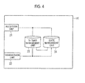
- the mobile station UE includes a reception unit 21, a transmission unit 22, a TA timer management unit 23, and a state management unit 24.
- the reception unit 21 is configured to receive a "UL grant”, a "Sync Request MAC CE”, and a "Timing Advance MAC CE", from the radio base station eNB., via PDCCH and PDSCH.
- the TA timer management unit 23 is configured to manage the TA timer corresponding to each CC used in the mobile station UE.
- the TA timer management unit 23 is configured to start the TA timer corresponding to each CC, when each CC is in a synchronous state.
- the TA timer management unit 23 is configured to start the TA timer corresponding to CC upon receiving the TA ("TA Command") corresponding to each CC from the radio base station eNB.
- the TA timer management unit 23 is configured to assign the TA that must be applied to each CC used in the mobile station UE, and manage the TA timer.
- the state management unit 24 is configured to manage the state (synchronous state or asynchronous state) of each CC used in the mobile station UE.
- the state management unit 24 is configured to set the state of the "Component Carrier", whose TA timer has expired, to the asynchronous state.
- the transmission unit 22 is configured to transmit an uplink data signal or an uplink control signal to the radio base station eNB, via PUSCH or PUCCH in a plurality of "Components Carriers" having different carrier frequencies.
- the transmission unit 22 may be configured to enable the transmission of an uplink data signal or an uplink control signal, via PUSCH or PUCCH in a "Component Carrier” in a synchronous state included in the plurality of "Component Carriers".
- the transmission unit 22 may be configured to transmit an uplink data signal, via PUSCH in the "Component Carrier".
- the transmission unit 22 may be configured to transmit "RACE Preamble", via PEACH (Physical Random Access Channel) in the "Component Carrier".
- the transmission unit 22 may be configured to transmit an "RACH Preamble” via PRACH in all "Component Carriers” that are in an asynchronous state.
- the transmission unit 22 may be configured to transmit an "RACH Preamble", via PRACH in the "Component Carrier” designated by the identification information "Carrier Indicator Field (CIF)" specified by the "Sync Request MAC CE” received from the radio base station eNB.
- RACH Preamble via PRACH in the "Component Carrier” designated by the identification information "Carrier Indicator Field (CIF)” specified by the "Sync Request MAC CE” received from the radio base station eNB.
- CIF Carrier Indicator Field
- the transmission unit 22 is configured to adjust the transmission timing of the uplink signal in each of the plurality of "Component Carriers", based on the TA received by the reception unit 21.
- the transmission unit 22 may adjust the transmission timing of the uplink signal in each of the plurality of "Component Carriers" processed by the same receiver (IFFT) within the mobile station UE, such that the transmission timing becomes the same.
- the transmission unit 22 may adjust the transmission timing of the uplink signal in each of the plurality of "Component Carriers", such that the transmission timing becomes the same.
- the transmission unit 22 may adjust the transmission timing of the uplink signal in each of the plurality of "Component Carriers" processed by different receivers (IFFT) within the mobile station UE, such that the transmission timing is different.
- IFFT receivers
- the transmission unit 22 may adjust the transmission timing of the uplink signal in each of the plurality of "Component Carriers", such that the transmission timing is different.
- the transmission unit 22 may adjust the transmission timing of the uplink signal in each group of the "Component Carrier" specified by the radio base station eNB.
- the reception timing of an uplink data signal in a radio base station eNB can be maintained within a constant range even when CA is performed.
- a first characteristic of the present embodiment is summarized as a mobile communication system having a mobile station UE, in which CA is performed, configured to transmit an uplink data signal to a radio base station eNB, by using a plurality of "Component Carriers (for example, CC #1, CC #2, CC #3, CC #11, CC #12, CC #21, CC #31, and CC #32)" having different carrier frequencies, and the mobile communication system includes TA timer management units 13 and 23 configured to manage the TA timer corresponding to the plurality of "Component Carriers", and state management units 14 and 24 configured to manage the state of the plurality of "Component Carriers", and the state management units 14 and 24 are configured to set the state of a "Component Carrier", whose TA timer has expired, to an asynchronous state.
- Component Carriers for example, CC #1, CC #2, CC #3, CC #11, CC #12, CC #21, CC #31, and CC #32
- the mobile station UE in which CA is performed, may be configured to enable the transmission of an uplink data signal using a "Component Carrier” in a synchronous state included in the plurality of "Component Carriers".
- the mobile station UE when the "Component Carrier" specified by the "UL Grant (scheduling signal)" or a synchronization request signal received from the radio base station eNB is in an asynchronous state, the mobile station UE, in which CA is performed, may be configured to transmit an "RANCH Preamble (random access signal)" in the "Component Carrier".
- RANCH Preamble random access signal
- the mobile station UE when a "Sync Request MAC CE (a predetermined signal)" is received from the radio base station eNB, the mobile station UE, in which CA is performed, may be configured to transmit an "RACH Preamble” in all “Component Carriers” that are in the asynchronous state.
- a second characteristic of the present embodiment is summarized as a radio base station eNB configured to receive an uplink data signal from a mobile station UE by using a plurality of "Component Carriers" of different frequency bands, and the radio base station eNB includes a TA timer management unit 13 configured to manage the TA timer corresponding to the plurality of "Component Carriers", and a state management unit 14 configured to manage the state of the plurality of "Component Carriers", and the state management unit 14 is configured to set the state of a "Component Carrier", whose TA timer has expired, to an asynchronous state.
- a third characteristic of the present embodiment is summarized as a mobile station UE configured to transmit an uplink data signal to a radio base station eNB by using a plurality of "Component Carriers" of different frequency bands, and the mobile station UE includes a TA timer management unit 23 configured to manage the TA timer corresponding to the plurality of "Component Carriers", and a state management unit 24 configured to manage the state of the plurality of "Component Carriers", and the state management unit 24 is configured to set the state of a "Component Carrier", whose TA timer has expired, to an asynchronous state.
- a transmission unit 22 configured to enable the transmission of an uplink data signal by using a "Component Carrier” in a synchronous state included in the plurality of "Component Carriers” may be included.
- a transmission unit 22 configured to transmit an "RACH Preamble" in the "Component Carrier” may be included.
- a transmission unit 22 configured to transmit an "RANCH Preamble” in all "Component Carriers” that are in the asynchronous state may be included.
- a group including one or more "Component Carriers" may be set, and a different TA timer may be set in each group.
- the operation of the above-described the radio base station eNB or the mobile station UE may be implemented by a hardware, may also be implemented by a software module executed by a processor, and may further be implemented by the combination of the both.
- the software module may be arranged in a storage medium of an arbitrary format such as RAM(Random Access Memory), a flash memory, ROM (Read Only Memory), EPROM (Erasable Programmable ROM), EEPROM (Electronically Erasable and Programmable ROM), a register, a hard disk, a removable disk, and CD-ROM.
- RAM Random Access Memory
- flash memory ROM (Read Only Memory)
- EPROM Erasable Programmable ROM
- EEPROM Electrical Erasable and Programmable ROM
- register a hard disk, a removable disk, and CD-ROM.
- the storage medium is connected to the processor so that the processor can write and read information into and from the storage medium.
- a storage medium may also be accumulated in the processor.
- the storage medium and processor may be arranged in ASIC.
- Such the ASIC may be arranged in the radio base station eNB or the mobile station UE. Further, such a storage medium or a processor may be arranged, as a discrete component, in the radio base station eNB or the mobile station UE.
Landscapes
- Engineering & Computer Science (AREA)
- Signal Processing (AREA)
- Computer Networks & Wireless Communication (AREA)
- Mobile Radio Communication Systems (AREA)
Abstract
Description
- The present invention relates to a mobile communication system, a radio base station, and a mobile station.
- In the LTE (Long Tern Evolution)-Advanced scheme for which the 3GPP is developing its use, "CA (Carrier Aggregation)" is under examination.
- When the CA is performed in a mobile station UE, the mobile station UE is configured to transmit an uplink signal by using a plurality of "Component Carriers (CCs)" of different frequency bands, to a radio base station eNB.
-
- [NPL 1] 3GPP TR36.814 v1.5.0
- [NPL 2] 3GPP TS36.321 v9.1.0
- However, a problem was that as shown in
Fig. 1 , when CA is performed in a mobile station UE by using "Component Carriers (for example,CC # 1 and CC #11)" in cells having a different coverage (for example, acell # 1 and a cell #11), and as shown inFig. 2 , when CA is performed in a mobile station UE by using a "Component Carrier (for example, CC #1)" in acell # 1 in which a repeater is not used, and a "Component Carrier (for example, CC #2)" in acell # 2 in which arepeater # 2 is used, the reception timing of an uplink signal in the radio base station eNB varies immensely in each "Component Carrier". - Therefore, the present invention has been achieved in view of the above problem, and an object thereof is to provide a mobile communication system, a radio base station, and a mobile station by which the reception timing of an uplink signal in a radio base station eNB can be maintained within a constant range even when CA is performed.
- A first characteristic of the present embodiment is summarized in that a mobile communication system having a mobile station configured to transmit an uplink signal to a radio base station by using a plurality of carriers having different carrier frequencies, comprising, a timer management unit configured to manage the timer corresponding to the plurality of carriers, and a state management unit configured to manage the state of the plurality of carriers, in which the state management unit is configured to set the state of a carrier, whose timer has expired, to an asynchronous state.
- A second characteristic of the present embodiment is summarized in that a radio base station configured to receive an uplink signal from a mobile station by using a plurality of carriers having different carrier frequencies, comprising, a timer management unit configured to manage the timer corresponding to the plurality of carriers, and a state management unit configured to manage the state of the plurality of carriers, in which the state management unit is configured to set the state of a carrier, whose timer has expired, to an asynchronous state.
- A third characteristic of the present embodiment is summarized in that a mobile station configured to transmit an uplink signal to a radio base station by using a plurality of carriers having different carrier frequencies, comprising, a timer management unit configured to manage the timer corresponding to the plurality of carriers, and a state management unit configured to manage the state of the plurality of carriers, in which the state management unit is configured to set the state of a carrier, whose timer has expired, to an asynchronous state.
- As described above, according to the present invention, it is possible to provide a mobile communication system, a radio base station, and a mobile station by which the reception timing of an uplink signal in a radio base station eNB can be maintained within a constant range even when CA is performed.
-
- [
Fig. 1] Fig. 1 is a diagram showing the entire configuration of a mobile communication system according to a first embodiment of the present invention. - [
Fig. 2] Fig. 2 is a diagram showing the entire configuration of the mobile communication system according to the first embodiment of the present invention. - [
Fig. 3] Fig. 3 is a functional block diagram of a radio base station according to the first embodiment of the present invention. - [
Fig. 4] Fig. 4 is a functional block diagram of a mobile station according to the first embodiment of the present invention. - With reference to
Fig. 1 to Fig. 4 , the configuration of a mobile communication system according to a first embodiment of the present invention will be described. - The mobile communication system according to the present embodiment is a mobile communication system of the LTE-Advanced scheme, and is configured to enable CA by a mobile station UE.
- For example, the mobile communication system according to the present embodiment may have a configuration as shown in
Fig. 1 , or a configuration as shown inFig. 2 , or any other configuration. - In the configuration shown in
Fig. 1 , acell # 1, acell # 2, and acell # 3 are provided as macro cells, and acell # 11, acell # 12, acell # 21, acell # 31, and acell # 32 are provided as flared cells subordinate to a radio base station eNB. - In this case, the
cell # 11 and thecell # 12 are provided within the coverage of thecell # 1, thecell # 21 is provided within the coverage of thecell # 2, and thecell # 31 and thecell # 32 are provided within the coverage of thecell # 3. - Furthermore, CC (Component Carrier) #1 is used in the
cell # 1,CC # 2 is used in thecell # 2,CC # 3 is used in thecell # 3,CC # 11 is used in thecell # 11,CC # 12 is used in thecell # 12,CC # 21 is used in thecell # 21,CC # 31 is used in thecell # 31, andCC # 32 is used in thecell # 32. - For example, the
CC # 1, theCC# 2, and theCC # 3 are "Component Carriers" having a carrier frequency in the 2-GHz band, and theCC# 11, theCC # 12, theCC # 21, theCC # 31, and theCC # 32 may be "Component Carriers" having a carrier frequency in the 3.5-GHz band. - For example, the bandwidth of the "Component Carriers" may be any one of 6 RB (Resource Blocks), 1.5 RB, 25 RB, 50 RB, 75 RB, or 100 RB. Note that 1 RB equals 180 kHz.
- Furthermore, in the configuration illustrated in
Fig. 2 , acell # 1 and acell # 2 are provided as macro cells subordinate to the radio base station eNB. TheCC # 1 is used in thecell # 1, and theCC # 2 is used in thecell # 2. - For example, both the
CC # 1 and theCC # 2, may be "Component Carriers" having a carrier frequency in the 2-GHz band (or 3.5-GHz band). Alternatively, theCC # 1 may be a "Component Carrier" having a carrier frequency in the 2-GHz band (or 3.5-GHz band), and theCC # 2 may be a "Component Carrier" having a carrier frequency in the 3.5-GHz band (or 2-GHz band). - In this case, a repeater (that is, booster) is not installed in the
cell # 1, and arepeater # 2 is installed in thecell # 2. - As illustrated in
Fig. 3 , the radio base station eNB includes areception unit 11, atransmission unit 12, a TAtimer management unit 13, and astate management unit 14. - The
reception unit 11 is configured to receive an uplink data signal or an uplink control signal transmitted from a mobile station UE by using PUSCH (Physical Uplink Shared Channel) or PUSSCH (Physical Uplink Control Channel) in a plurality of "Components Carriers" having different carrier frequencies. - The TA
timer management unit 13 is configured to manage a TA (Timing Advande, transmission timing adjustment information) timer corresponding to each CC used in each mobile station UE in which CA is performed. - In this case, the TA
timer management unit 13 is configured to start the TA timer corresponding to each CC, when each CC is in a synchronous state. - Alternatively, the TA.
timer management unit 13 is configured to start the TA timer corresponding to CC upon receiving the TA ("TA Command") corresponding to each CC from the radio base station eNB. - Furthermore, the TA
timer management unit 13 is configured to assign and manage the TA that must be applied to each CC used in each mobile station UE in which CA is performed. - In this case, the TA
timer management unit 13 may be configured to assign the same TA to a plurality of "Component Carriers" processed by the same receiver (IFFT: Inverse Fast Fourier Transform; inverse Fourier transformer) within each mobile station UE in which CA is performed. - That is, the TA
timer management unit 13 may be configured to assign only a single TA to a mobile station UE in which only "contiguous CA" is performed. In this case, the "contiguous CA" is CA processed by a single receiver (IFFT). - In "Component Carriers" processed by the same receiver (IFFT), if separate TAs are used, the orthogonality among the OFDM subcarriers spanning the "Component Carriers" is no longer maintained, and therefore, the same TA must be used. Therefore, the above configuration is achieved.
- On the other hand, the TA
timer management unit 13 may be configured to assign different TAs to a plurality of "Component Carriers" processed by different receivers (IFFT) within each mobile station UE in which CA is performed. - That is, the TA
timer management unit 13 is configured to independently assign TA to each of the plurality of "Component Carriers" for which a "non-contiguous CA" is to be performed, in a mobile station UE in which the "non-contiguous CA" is performed. In this case, the "non-contiguous CA" is CA processed by a plurality of receivers (IFFT). - Furthermore, the TA
timer management unit 13 may be configured to assign different TAs to each group of "Component Carriers" specified by the radio base station eNB. - The
state management unit 14 is configured to manage the state (synchronous state or asynchronous state) of each CC used in each mobile station UE in which CA is performed. - In this case, the
state management unit 14 is configured to set the state of the "Component Carrier", whose TA timer has expired, to the asynchronous state. - The
transmission unit 12 is configured to transmit a "UL grant" and a "Sync Request MAC (Media Access Control) CE (Control Element)" to the mobile station UE in which CA is performed, via PDCCH (Physical Downlink Control Channel) and PDSCH (Physical Downlink Shared Channel). - Furthermore, the
transmission unit 12 is configured to transmit the TA assigned to each of the plurality of "Component Carriers", to the mobile station UE in which CA is performed. - Furthermore, the
transmission unit 12 may be configured to transmit the aforementioned TA to the mobile station UE in which CA is performed, with the help of a "Timing Advance MAC CE". - The "Timing Advance MAC CE" specifies the value of the TA that must be applied, as well as the identifier of the "Component Carrier" or the group thereof to which the TA must be applied.
- The
transmission unit 12 may be configured to transmit the aforementioned TA to the mobile station UE in which CA is performed, via an "Anchor Carriers". - In this case, an Anchor Carrier may be defined as a carrier, from among a plurality of "Component Carriers", to which a PDCCH (Physical Downlink Control Channel) signal is transmitted, or a carrier to which a PHICH (Physical HARQ Indicator Channel) signal is transmitted, or a carrier to which a downlink signal, in which a "Semi-persistent Scheduling" has been applied, is transmitted, or a carrier to which a PHICH signal corresponding to a PUSCH signal (uplink data signal), in which a "Semi-persistent Scheduling" has been applied, is transmitted, or a carrier to which a paging signal is transmitted, or a carrier to which a DCCH (Dedicated Control Channel) signal is transmitted, or else a carrier for which measurement (measurement) is performed. Alternatively, the Anchor Carrier may be defined by a combination of the aforementioned definitions.
- The aforementioned DCCH signal may include a "Measurement Report (measurement report)", a "Handover Command (handover command signal)", or a "Handover Complete (handover complete signal)".
- Furthermore, the "Anchor Carrier" may be called the "Main Carrier".
- The
transmission unit 12 may be configured to transmit the aforementioned TA to the mobile station UE in which CA is performed, via any carrier other than the Anchor Carrier. - Furthermore, the
transmission unit 12 may be configured to specify a carrier for transmitting the aforementioned TA, by an individual control signal or a broadcast signal. - As illustrated in
Fig. 4 , the mobile station UE includes areception unit 21, atransmission unit 22, a TAtimer management unit 23, and astate management unit 24. - The
reception unit 21 is configured to receive a "UL grant", a "Sync Request MAC CE", and a "Timing Advance MAC CE", from the radio base station eNB., via PDCCH and PDSCH. - When CA is performed in the mobile station UE, the TA
timer management unit 23 is configured to manage the TA timer corresponding to each CC used in the mobile station UE. - In this case, the TA
timer management unit 23 is configured to start the TA timer corresponding to each CC, when each CC is in a synchronous state. - Alternatively, the TA
timer management unit 23 is configured to start the TA timer corresponding to CC upon receiving the TA ("TA Command") corresponding to each CC from the radio base station eNB. - Furthermore, the TA
timer management unit 23 is configured to assign the TA that must be applied to each CC used in the mobile station UE, and manage the TA timer. - When CA is performed in the mobile station UE, the
state management unit 24 is configured to manage the state (synchronous state or asynchronous state) of each CC used in the mobile station UE. - In this case, the
state management unit 24 is configured to set the state of the "Component Carrier", whose TA timer has expired, to the asynchronous state. - When CA is performed in the mobile station UE, the
transmission unit 22 is configured to transmit an uplink data signal or an uplink control signal to the radio base station eNB, via PUSCH or PUCCH in a plurality of "Components Carriers" having different carrier frequencies. - Even when the plurality of "Component Carriers" include a "Component Carrier" in an asynchronous state, the
transmission unit 22 may be configured to enable the transmission of an uplink data signal or an uplink control signal, via PUSCH or PUCCH in a "Component Carrier" in a synchronous state included in the plurality of "Component Carriers". - Furthermore, when the "Component Carrier" designated by the identification information "Carrier Indicator Field (CIF)" specified by a "UL grant" is in a synchronous state, the
transmission unit 22 may be configured to transmit an uplink data signal, via PUSCH in the "Component Carrier". - On the other hand, when the "Component Carrier" designated by the identification information "Carrier Indicator Field (CIF)" specified by a "UL grant" is in an asynchronous state, the
transmission unit 22 may be configured to transmit "RACE Preamble", via PEACH (Physical Random Access Channel) in the "Component Carrier". - Furthermore, when a "Sync Request MAC CE" is received from the radio base station eNB, the
transmission unit 22 may be configured to transmit an "RACH Preamble" via PRACH in all "Component Carriers" that are in an asynchronous state. - Alternatively, the
transmission unit 22 may be configured to transmit an "RACH Preamble", via PRACH in the "Component Carrier" designated by the identification information "Carrier Indicator Field (CIF)" specified by the "Sync Request MAC CE" received from the radio base station eNB. - Furthermore, the
transmission unit 22 is configured to adjust the transmission timing of the uplink signal in each of the plurality of "Component Carriers", based on the TA received by thereception unit 21. - The
transmission unit 22 may adjust the transmission timing of the uplink signal in each of the plurality of "Component Carriers" processed by the same receiver (IFFT) within the mobile station UE, such that the transmission timing becomes the same. - That is, when the "contiguous CA" is performed in the mobile station UE, the
transmission unit 22 may adjust the transmission timing of the uplink signal in each of the plurality of "Component Carriers", such that the transmission timing becomes the same. - On the other hand, the
transmission unit 22 may adjust the transmission timing of the uplink signal in each of the plurality of "Component Carriers" processed by different receivers (IFFT) within the mobile station UE, such that the transmission timing is different. - That is, when a "non-Contiguous CA" is performed in the mobile station UE, the
transmission unit 22 may adjust the transmission timing of the uplink signal in each of the plurality of "Component Carriers", such that the transmission timing is different. - Furthermore, the
transmission unit 22 may adjust the transmission timing of the uplink signal in each group of the "Component Carrier" specified by the radio base station eNB. - According to the mobile communication system of the first embodiment of the present invention, because TA can be assigned to each CC used in a mobile station UE in which CA is performed, the reception timing of an uplink data signal in a radio base station eNB can be maintained within a constant range even when CA is performed.
- Furthermore, according to the mobile communication system of the first embodiment of the present invention, because the synchronization process can be performed again for a component Carrier" whose timer has expired, accurate synchronization can be achieved between the mobile station UE and the radio base station eNB, in each "Component Carrier".
- The characteristics of the present embodiment as described above may be expressed as follows.
- A first characteristic of the present embodiment is summarized as a mobile communication system having a mobile station UE, in which CA is performed, configured to transmit an uplink data signal to a radio base station eNB, by using a plurality of "Component Carriers (for example,
CC # 1,CC # 2,CC # 3,CC # 11,CC # 12,CC # 21,CC # 31, and CC #32)" having different carrier frequencies, and the mobile communication system includes TAtimer management units state management units state management units - In the first characteristic of the present embodiment, even when the plurality of "Component Carriers" include a "Component Carrier" in an asynchronous state, the mobile station UE, in which CA is performed, may be configured to enable the transmission of an uplink data signal using a "Component Carrier" in a synchronous state included in the plurality of "Component Carriers".
- In the first characteristic of the present embodiment, when the "Component Carrier" specified by the "UL Grant (scheduling signal)" or a synchronization request signal received from the radio base station eNB is in an asynchronous state, the mobile station UE, in which CA is performed, may be configured to transmit an "RANCH Preamble (random access signal)" in the "Component Carrier".
- In the first characteristic of the present embodiment, when a "Sync Request MAC CE (a predetermined signal)" is received from the radio base station eNB, the mobile station UE, in which CA is performed, may be configured to transmit an "RACH Preamble" in all "Component Carriers" that are in the asynchronous state.
- A second characteristic of the present embodiment is summarized as a radio base station eNB configured to receive an uplink data signal from a mobile station UE by using a plurality of "Component Carriers" of different frequency bands, and the radio base station eNB includes a TA
timer management unit 13 configured to manage the TA timer corresponding to the plurality of "Component Carriers", and astate management unit 14 configured to manage the state of the plurality of "Component Carriers", and thestate management unit 14 is configured to set the state of a "Component Carrier", whose TA timer has expired, to an asynchronous state. - A third characteristic of the present embodiment is summarized as a mobile station UE configured to transmit an uplink data signal to a radio base station eNB by using a plurality of "Component Carriers" of different frequency bands, and the mobile station UE includes a TA
timer management unit 23 configured to manage the TA timer corresponding to the plurality of "Component Carriers", and astate management unit 24 configured to manage the state of the plurality of "Component Carriers", and thestate management unit 24 is configured to set the state of a "Component Carrier", whose TA timer has expired, to an asynchronous state. - In the third characteristic of the present embodiment, even when the plurality of "Component Carriers" include a "Component Carrier" in, an asynchronous state, a
transmission unit 22 configured to enable the transmission of an uplink data signal by using a "Component Carrier" in a synchronous state included in the plurality of "Component Carriers" may be included. - In the third characteristic of the present embodiment, when the "Component Carrier" specified by the "UL Grant" or a synchronization request signal received from the radio base station eNB is in an asynchronous state, a
transmission unit 22 configured to transmit an "RACH Preamble" in the "Component Carrier" may be included. - In the third characteristic of the present embodiment, when a "Sync Request MAC CE" is received from the radio base station eNB, a
transmission unit 22 configured to transmit an "RANCH Preamble" in all "Component Carriers" that are in the asynchronous state may be included. - According to a fourth characteristic of the present embodiment, a group including one or more "Component Carriers" may be set, and a different TA timer may be set in each group.
- It is noted that the operation of the above-described the radio base station eNB or the mobile station UE may be implemented by a hardware, may also be implemented by a software module executed by a processor, and may further be implemented by the combination of the both.
- The software module may be arranged in a storage medium of an arbitrary format such as RAM(Random Access Memory), a flash memory, ROM (Read Only Memory), EPROM (Erasable Programmable ROM), EEPROM (Electronically Erasable and Programmable ROM), a register, a hard disk, a removable disk, and CD-ROM.
- The storage medium is connected to the processor so that the processor can write and read information into and from the storage medium. Such a storage medium may also be accumulated in the processor. The storage medium and processor may be arranged in ASIC. Such the ASIC may be arranged in the radio base station eNB or the mobile station UE. Further, such a storage medium or a processor may be arranged, as a discrete component, in the radio base station eNB or the mobile station UE.
- Thus, the present invention has been explained in detail by using the above-described embodiments; however, it is obvious that for persons skilled in the art, the present invention is not limited to the embodiments explained herein. The present invention can be implemented as a corrected and modified mode without departing from the gist and the scope of the present invention defined by the claims. Therefore, the description of the specification is intended for explaining the example only and does not impose any limited meaning to the present invention.
Claims (9)
- A mobile communication system having a mobile station configured to transmit an uplink signal to a radio base station by using a plurality of carriers having different carrier frequencies, comprising:a timer management unit configured to manage the timer corresponding to the plurality of carriers; anda state management unit configured to manage the state of the plurality of carriers, whereinthe state management unit is configured to set the state of a carrier, whose timer has expired, to an asynchronous state.
- The mobile communication system according to claim 1, wherein even when the plurality of carriers include a carrier in an asynchronous state, the mobile station is configured to enable the transmission of an uplink signal using a carrier in a synchronous state included in the plurality of carriers.
- The mobile communication system according to claim 1, wherein when the carrier specified by a scheduling signal or a synchronization request signal received from the radio base station is in an asynchronous state, the mobile station is configured to transmit a random access signal in the carrier.
- The mobile communication system according to claim 1, wherein when a predetermined signal is received from the radio base station, the mobile station is configured to transmit a random access signal in all carriers that are in the asynchronous state.
- A radio base station configured to receive an uplink signal from a mobile station by using a plurality of carriers having different carrier frequencies, comprising:a timer management unit configured to manage the timer corresponding to the plurality of carriers; anda state management unit configured to manage the state of the plurality of carriers, whereinthe state management unit is configured to set the state of a carrier, whose timer has expired, to an asynchronous state.
- A mobile station configured to transmit an uplink signal to a radio base station by using a plurality of carriers having different carrier frequencies, comprising:a timer management unit configured to manage the timer corresponding to the plurality of carriers; anda state management unit configured to manage the state of the plurality of carriers, whereinthe state management unit is configured to set the state of a carrier, whose timer has expired, to an asynchronous state.
- The mobile station according to claim 6, comprising, a transmission unit configured to enable the transmission of an uplink signal using a carrier of a synchronous state included in the plurality of carriers even when the plurality of carriers include a carrier of an asynchronous state.
- The mobile station according to claim 6, comprising a transmission unit configured to transmit a random access signal in the carrier, when the carrier specified by a scheduling signal or a synchronization request signal received from the radio base station is in an asynchronous state.
- The mobile station according to claim 6, comprising a transmission unit configured to transmit a random access signal in all carriers that are in the asynchronous state, when a predetermined signal is received from the radio base station.
Priority Applications (2)
| Application Number | Priority Date | Filing Date | Title |
|---|---|---|---|
| PL19179096T PL3557928T3 (en) | 2010-01-08 | 2011-01-07 | MOBILE STATION FOR MULTIPLE COMMUNICATION CARRIERS |
| EP19179096.3A EP3557928B1 (en) | 2010-01-08 | 2011-01-07 | A mobile station for a plurality of communication carriers |
Applications Claiming Priority (2)
| Application Number | Priority Date | Filing Date | Title |
|---|---|---|---|
| JP2010003378 | 2010-01-08 | ||
| PCT/JP2011/050216 WO2011083865A1 (en) | 2010-01-08 | 2011-01-07 | Mobile communication system, radio base station and mobile station |
Related Child Applications (2)
| Application Number | Title | Priority Date | Filing Date |
|---|---|---|---|
| EP19179096.3A Division EP3557928B1 (en) | 2010-01-08 | 2011-01-07 | A mobile station for a plurality of communication carriers |
| EP19179096.3A Division-Into EP3557928B1 (en) | 2010-01-08 | 2011-01-07 | A mobile station for a plurality of communication carriers |
Publications (3)
| Publication Number | Publication Date |
|---|---|
| EP2523512A1 true EP2523512A1 (en) | 2012-11-14 |
| EP2523512A4 EP2523512A4 (en) | 2016-08-24 |
| EP2523512B1 EP2523512B1 (en) | 2019-07-24 |
Family
ID=44305600
Family Applications (2)
| Application Number | Title | Priority Date | Filing Date |
|---|---|---|---|
| EP19179096.3A Active EP3557928B1 (en) | 2010-01-08 | 2011-01-07 | A mobile station for a plurality of communication carriers |
| EP11731863.4A Active EP2523512B1 (en) | 2010-01-08 | 2011-01-07 | Mobile communication system, radio base station and mobile station |
Family Applications Before (1)
| Application Number | Title | Priority Date | Filing Date |
|---|---|---|---|
| EP19179096.3A Active EP3557928B1 (en) | 2010-01-08 | 2011-01-07 | A mobile station for a plurality of communication carriers |
Country Status (11)
| Country | Link |
|---|---|
| US (1) | US9520969B2 (en) |
| EP (2) | EP3557928B1 (en) |
| JP (1) | JP5199488B2 (en) |
| KR (1) | KR101439939B1 (en) |
| CN (1) | CN102763468B (en) |
| AU (1) | AU2011204138B2 (en) |
| BR (1) | BR112012016889A2 (en) |
| PH (1) | PH12012501384A1 (en) |
| PL (1) | PL3557928T3 (en) |
| RU (1) | RU2523261C2 (en) |
| WO (1) | WO2011083865A1 (en) |
Cited By (1)
| Publication number | Priority date | Publication date | Assignee | Title |
|---|---|---|---|---|
| EP2941031A4 (en) * | 2012-12-28 | 2016-12-14 | Ntt Docomo Inc | Mobile station and wireless base station |
Families Citing this family (5)
| Publication number | Priority date | Publication date | Assignee | Title |
|---|---|---|---|---|
| JP5778539B2 (en) * | 2011-09-22 | 2015-09-16 | 株式会社Nttドコモ | Base station and communication control method |
| WO2014101229A1 (en) | 2012-12-31 | 2014-07-03 | 华为技术有限公司 | Data transmission method and base station |
| US20180049079A1 (en) * | 2016-08-12 | 2018-02-15 | Qualcomm Incorporated | Handover in wireless communications |
| US11304164B2 (en) * | 2016-11-18 | 2022-04-12 | Qualcomm Incorporated | Asynchronous CA handling |
| CN110831145B (en) | 2018-08-09 | 2021-05-18 | 华为技术有限公司 | Method and apparatus for wireless communication |
Family Cites Families (15)
| Publication number | Priority date | Publication date | Assignee | Title |
|---|---|---|---|---|
| JP4652846B2 (en) * | 2004-03-11 | 2011-03-16 | パナソニック株式会社 | Communication terminal device and communication relay method |
| EP2016689B1 (en) * | 2006-05-01 | 2017-06-21 | Nokia Technologies Oy | Apparatus, method and computer program product providing uplink synchronization through use of dedicated uplink resource assignment |
| EA016365B1 (en) * | 2007-08-08 | 2012-04-30 | Шарп Кабусики Кайся | RADIO COMMUNICATION SYSTEM AND MOBILE STATION DEVICE |
| US20090046641A1 (en) * | 2007-08-13 | 2009-02-19 | Interdigital Patent Holdings, Inc. | Long term evolution medium access control procedures |
| US8681711B2 (en) | 2007-10-05 | 2014-03-25 | Qualcomm Incorporated | Inactivity-based multi-carrier allocation in wireless networks |
| WO2009084998A1 (en) * | 2008-01-03 | 2009-07-09 | Telefonaktiebolaget Lm Ericsson (Publ) | Fast radio link recovery after handover failure |
| AR073832A1 (en) * | 2008-10-20 | 2010-12-01 | Interdigital Patent Holdings | SIGNALING AND ACQUISITION OF CONTROL CHANNEL TO ADD CARRIER WAVE |
| WO2010078365A1 (en) * | 2008-12-30 | 2010-07-08 | Interdigital Patent Holdings, Inc. | Discontinuous reception for carrier aggregation |
| KR20110126651A (en) * | 2009-02-04 | 2011-11-23 | 텔레폰악티에볼라겟엘엠에릭슨(펍) | Anchor Carrier Selection Technology in Telecommunication Systems |
| WO2010099105A1 (en) * | 2009-02-27 | 2010-09-02 | Interdigital Patent Holdings, Inc. | Anchor carrier reselection and cell reselection in long term evolution-advanced |
| US9125090B2 (en) * | 2009-02-27 | 2015-09-01 | At&T Mobility Ii Llc | Staggered channelization code allocation for multi-carrier networks |
| CN101510867A (en) * | 2009-03-17 | 2009-08-19 | 中兴通讯股份有限公司 | Method and apparatus for sending synchronization signal |
| CN101588629B (en) * | 2009-06-16 | 2015-08-12 | 中兴通讯股份有限公司 | The determination method and apparatus of DL synchronization component carrier wave in a kind of carrier aggregation system |
| US9042840B2 (en) * | 2009-11-02 | 2015-05-26 | Qualcomm Incorporated | Cross-carrier/cross-subframe indication in a multi-carrier wireless network |
| CN104980264B (en) * | 2010-07-27 | 2019-06-14 | 索尼公司 | Electronic device, method for terminal device and base station, and storage device |
-
2011
- 2011-01-07 CN CN201180005634.0A patent/CN102763468B/en active Active
- 2011-01-07 US US13/521,074 patent/US9520969B2/en active Active
- 2011-01-07 JP JP2011549041A patent/JP5199488B2/en active Active
- 2011-01-07 KR KR1020127017891A patent/KR101439939B1/en not_active Expired - Fee Related
- 2011-01-07 WO PCT/JP2011/050216 patent/WO2011083865A1/en not_active Ceased
- 2011-01-07 PH PH1/2012/501384A patent/PH12012501384A1/en unknown
- 2011-01-07 EP EP19179096.3A patent/EP3557928B1/en active Active
- 2011-01-07 BR BR112012016889A patent/BR112012016889A2/en not_active IP Right Cessation
- 2011-01-07 RU RU2012133084/07A patent/RU2523261C2/en not_active IP Right Cessation
- 2011-01-07 PL PL19179096T patent/PL3557928T3/en unknown
- 2011-01-07 AU AU2011204138A patent/AU2011204138B2/en not_active Ceased
- 2011-01-07 EP EP11731863.4A patent/EP2523512B1/en active Active
Non-Patent Citations (1)
| Title |
|---|
| See references of WO2011083865A1 * |
Cited By (2)
| Publication number | Priority date | Publication date | Assignee | Title |
|---|---|---|---|---|
| EP2941031A4 (en) * | 2012-12-28 | 2016-12-14 | Ntt Docomo Inc | Mobile station and wireless base station |
| US9788191B2 (en) | 2012-12-28 | 2017-10-10 | Ntt Docomo, Inc | Mobile station and radio base station |
Also Published As
| Publication number | Publication date |
|---|---|
| PL3557928T3 (en) | 2022-05-23 |
| CN102763468A (en) | 2012-10-31 |
| KR20120102766A (en) | 2012-09-18 |
| BR112012016889A2 (en) | 2019-09-24 |
| US9520969B2 (en) | 2016-12-13 |
| AU2011204138A1 (en) | 2012-08-09 |
| AU2011204138B2 (en) | 2014-04-03 |
| EP3557928A1 (en) | 2019-10-23 |
| EP2523512B1 (en) | 2019-07-24 |
| JPWO2011083865A1 (en) | 2013-05-16 |
| RU2523261C2 (en) | 2014-07-20 |
| WO2011083865A1 (en) | 2011-07-14 |
| PH12012501384A1 (en) | 2015-02-27 |
| RU2012133084A (en) | 2014-02-20 |
| EP3557928B1 (en) | 2022-03-16 |
| JP5199488B2 (en) | 2013-05-15 |
| US20120327924A1 (en) | 2012-12-27 |
| KR101439939B1 (en) | 2014-09-15 |
| EP2523512A4 (en) | 2016-08-24 |
| CN102763468B (en) | 2016-08-24 |
Similar Documents
| Publication | Publication Date | Title |
|---|---|---|
| US11729814B2 (en) | Channel access configuration | |
| US10728077B2 (en) | Method and apparatus for performing random access procedure in NB-IoT carrier in wireless communication system | |
| US8755298B2 (en) | Method and apparatus for random access in a wireless communication system | |
| CN102325382B (en) | Accidental access method and equipment | |
| US11076357B2 (en) | Uplink power control on unlicensed carriers | |
| US20140112308A1 (en) | Apparatus and method for performing uplink synchronization in multi-component carrier system | |
| US20190313450A1 (en) | Timing advance in lbt systems | |
| CN107926035B (en) | A first communication device and method thereof for sending one or more control signals to a second communication device | |
| US9520969B2 (en) | Mobile communication system, radio base station, and mobile station | |
| US8923200B2 (en) | Mobile communication method, radio base station, and mobile station | |
| WO2019215670A1 (en) | Physical random access channel arrangement for new radio unlicensed | |
| HK1252525B (en) | First communication device and methods therein, for sending one or more control signals to a second communication device |
Legal Events
| Date | Code | Title | Description |
|---|---|---|---|
| PUAI | Public reference made under article 153(3) epc to a published international application that has entered the european phase |
Free format text: ORIGINAL CODE: 0009012 |
|
| 17P | Request for examination filed |
Effective date: 20120807 |
|
| AK | Designated contracting states |
Kind code of ref document: A1 Designated state(s): AL AT BE BG CH CY CZ DE DK EE ES FI FR GB GR HR HU IE IS IT LI LT LU LV MC MK MT NL NO PL PT RO RS SE SI SK SM TR |
|
| DAX | Request for extension of the european patent (deleted) | ||
| RA4 | Supplementary search report drawn up and despatched (corrected) |
Effective date: 20160725 |
|
| RIC1 | Information provided on ipc code assigned before grant |
Ipc: H04W 56/00 20090101AFI20160719BHEP Ipc: H04W 76/06 20090101ALI20160719BHEP Ipc: H04W 74/08 20090101ALI20160719BHEP Ipc: H04W 72/00 20090101ALI20160719BHEP |
|
| STAA | Information on the status of an ep patent application or granted ep patent |
Free format text: STATUS: EXAMINATION IS IN PROGRESS |
|
| 17Q | First examination report despatched |
Effective date: 20170622 |
|
| REG | Reference to a national code |
Ref country code: DE Ref legal event code: R079 Ref document number: 602011060665 Country of ref document: DE Free format text: PREVIOUS MAIN CLASS: H04W0056000000 Ipc: H04W0072000000 |
|
| GRAP | Despatch of communication of intention to grant a patent |
Free format text: ORIGINAL CODE: EPIDOSNIGR1 |
|
| STAA | Information on the status of an ep patent application or granted ep patent |
Free format text: STATUS: GRANT OF PATENT IS INTENDED |
|
| RIC1 | Information provided on ipc code assigned before grant |
Ipc: H04L 5/00 20060101ALI20190117BHEP Ipc: H04W 56/00 20090101ALI20190117BHEP Ipc: H04W 72/00 20090101AFI20190117BHEP |
|
| INTG | Intention to grant announced |
Effective date: 20190218 |
|
| GRAS | Grant fee paid |
Free format text: ORIGINAL CODE: EPIDOSNIGR3 |
|
| GRAA | (expected) grant |
Free format text: ORIGINAL CODE: 0009210 |
|
| STAA | Information on the status of an ep patent application or granted ep patent |
Free format text: STATUS: THE PATENT HAS BEEN GRANTED |
|
| RAP1 | Party data changed (applicant data changed or rights of an application transferred) |
Owner name: NTT DOCOMO, INC. |
|
| AK | Designated contracting states |
Kind code of ref document: B1 Designated state(s): AL AT BE BG CH CY CZ DE DK EE ES FI FR GB GR HR HU IE IS IT LI LT LU LV MC MK MT NL NO PL PT RO RS SE SI SK SM TR |
|
| REG | Reference to a national code |
Ref country code: GB Ref legal event code: FG4D |
|
| REG | Reference to a national code |
Ref country code: CH Ref legal event code: EP |
|
| REG | Reference to a national code |
Ref country code: DE Ref legal event code: R096 Ref document number: 602011060665 Country of ref document: DE |
|
| REG | Reference to a national code |
Ref country code: AT Ref legal event code: REF Ref document number: 1159825 Country of ref document: AT Kind code of ref document: T Effective date: 20190815 |
|
| REG | Reference to a national code |
Ref country code: IE Ref legal event code: FG4D |
|
| REG | Reference to a national code |
Ref country code: NL Ref legal event code: MP Effective date: 20190724 |
|
| REG | Reference to a national code |
Ref country code: LT Ref legal event code: MG4D |
|
| REG | Reference to a national code |
Ref country code: AT Ref legal event code: MK05 Ref document number: 1159825 Country of ref document: AT Kind code of ref document: T Effective date: 20190724 |
|
| PG25 | Lapsed in a contracting state [announced via postgrant information from national office to epo] |
Ref country code: FI Free format text: LAPSE BECAUSE OF FAILURE TO SUBMIT A TRANSLATION OF THE DESCRIPTION OR TO PAY THE FEE WITHIN THE PRESCRIBED TIME-LIMIT Effective date: 20190724 Ref country code: SE Free format text: LAPSE BECAUSE OF FAILURE TO SUBMIT A TRANSLATION OF THE DESCRIPTION OR TO PAY THE FEE WITHIN THE PRESCRIBED TIME-LIMIT Effective date: 20190724 Ref country code: NO Free format text: LAPSE BECAUSE OF FAILURE TO SUBMIT A TRANSLATION OF THE DESCRIPTION OR TO PAY THE FEE WITHIN THE PRESCRIBED TIME-LIMIT Effective date: 20191024 Ref country code: BG Free format text: LAPSE BECAUSE OF FAILURE TO SUBMIT A TRANSLATION OF THE DESCRIPTION OR TO PAY THE FEE WITHIN THE PRESCRIBED TIME-LIMIT Effective date: 20191024 Ref country code: AT Free format text: LAPSE BECAUSE OF FAILURE TO SUBMIT A TRANSLATION OF THE DESCRIPTION OR TO PAY THE FEE WITHIN THE PRESCRIBED TIME-LIMIT Effective date: 20190724 Ref country code: HR Free format text: LAPSE BECAUSE OF FAILURE TO SUBMIT A TRANSLATION OF THE DESCRIPTION OR TO PAY THE FEE WITHIN THE PRESCRIBED TIME-LIMIT Effective date: 20190724 Ref country code: PT Free format text: LAPSE BECAUSE OF FAILURE TO SUBMIT A TRANSLATION OF THE DESCRIPTION OR TO PAY THE FEE WITHIN THE PRESCRIBED TIME-LIMIT Effective date: 20191125 Ref country code: NL Free format text: LAPSE BECAUSE OF FAILURE TO SUBMIT A TRANSLATION OF THE DESCRIPTION OR TO PAY THE FEE WITHIN THE PRESCRIBED TIME-LIMIT Effective date: 20190724 Ref country code: LT Free format text: LAPSE BECAUSE OF FAILURE TO SUBMIT A TRANSLATION OF THE DESCRIPTION OR TO PAY THE FEE WITHIN THE PRESCRIBED TIME-LIMIT Effective date: 20190724 |
|
| PG25 | Lapsed in a contracting state [announced via postgrant information from national office to epo] |
Ref country code: AL Free format text: LAPSE BECAUSE OF FAILURE TO SUBMIT A TRANSLATION OF THE DESCRIPTION OR TO PAY THE FEE WITHIN THE PRESCRIBED TIME-LIMIT Effective date: 20190724 Ref country code: LV Free format text: LAPSE BECAUSE OF FAILURE TO SUBMIT A TRANSLATION OF THE DESCRIPTION OR TO PAY THE FEE WITHIN THE PRESCRIBED TIME-LIMIT Effective date: 20190724 Ref country code: GR Free format text: LAPSE BECAUSE OF FAILURE TO SUBMIT A TRANSLATION OF THE DESCRIPTION OR TO PAY THE FEE WITHIN THE PRESCRIBED TIME-LIMIT Effective date: 20191025 Ref country code: ES Free format text: LAPSE BECAUSE OF FAILURE TO SUBMIT A TRANSLATION OF THE DESCRIPTION OR TO PAY THE FEE WITHIN THE PRESCRIBED TIME-LIMIT Effective date: 20190724 Ref country code: RS Free format text: LAPSE BECAUSE OF FAILURE TO SUBMIT A TRANSLATION OF THE DESCRIPTION OR TO PAY THE FEE WITHIN THE PRESCRIBED TIME-LIMIT Effective date: 20190724 Ref country code: IS Free format text: LAPSE BECAUSE OF FAILURE TO SUBMIT A TRANSLATION OF THE DESCRIPTION OR TO PAY THE FEE WITHIN THE PRESCRIBED TIME-LIMIT Effective date: 20191124 |
|
| PG25 | Lapsed in a contracting state [announced via postgrant information from national office to epo] |
Ref country code: TR Free format text: LAPSE BECAUSE OF FAILURE TO SUBMIT A TRANSLATION OF THE DESCRIPTION OR TO PAY THE FEE WITHIN THE PRESCRIBED TIME-LIMIT Effective date: 20190724 |
|
| PG25 | Lapsed in a contracting state [announced via postgrant information from national office to epo] |
Ref country code: RO Free format text: LAPSE BECAUSE OF FAILURE TO SUBMIT A TRANSLATION OF THE DESCRIPTION OR TO PAY THE FEE WITHIN THE PRESCRIBED TIME-LIMIT Effective date: 20190724 Ref country code: PL Free format text: LAPSE BECAUSE OF FAILURE TO SUBMIT A TRANSLATION OF THE DESCRIPTION OR TO PAY THE FEE WITHIN THE PRESCRIBED TIME-LIMIT Effective date: 20190724 Ref country code: DK Free format text: LAPSE BECAUSE OF FAILURE TO SUBMIT A TRANSLATION OF THE DESCRIPTION OR TO PAY THE FEE WITHIN THE PRESCRIBED TIME-LIMIT Effective date: 20190724 Ref country code: IT Free format text: LAPSE BECAUSE OF FAILURE TO SUBMIT A TRANSLATION OF THE DESCRIPTION OR TO PAY THE FEE WITHIN THE PRESCRIBED TIME-LIMIT Effective date: 20190724 Ref country code: EE Free format text: LAPSE BECAUSE OF FAILURE TO SUBMIT A TRANSLATION OF THE DESCRIPTION OR TO PAY THE FEE WITHIN THE PRESCRIBED TIME-LIMIT Effective date: 20190724 |
|
| PG25 | Lapsed in a contracting state [announced via postgrant information from national office to epo] |
Ref country code: SK Free format text: LAPSE BECAUSE OF FAILURE TO SUBMIT A TRANSLATION OF THE DESCRIPTION OR TO PAY THE FEE WITHIN THE PRESCRIBED TIME-LIMIT Effective date: 20190724 Ref country code: SM Free format text: LAPSE BECAUSE OF FAILURE TO SUBMIT A TRANSLATION OF THE DESCRIPTION OR TO PAY THE FEE WITHIN THE PRESCRIBED TIME-LIMIT Effective date: 20190724 Ref country code: CZ Free format text: LAPSE BECAUSE OF FAILURE TO SUBMIT A TRANSLATION OF THE DESCRIPTION OR TO PAY THE FEE WITHIN THE PRESCRIBED TIME-LIMIT Effective date: 20190724 Ref country code: IS Free format text: LAPSE BECAUSE OF FAILURE TO SUBMIT A TRANSLATION OF THE DESCRIPTION OR TO PAY THE FEE WITHIN THE PRESCRIBED TIME-LIMIT Effective date: 20200224 |
|
| REG | Reference to a national code |
Ref country code: DE Ref legal event code: R097 Ref document number: 602011060665 Country of ref document: DE |
|
| PLBE | No opposition filed within time limit |
Free format text: ORIGINAL CODE: 0009261 |
|
| STAA | Information on the status of an ep patent application or granted ep patent |
Free format text: STATUS: NO OPPOSITION FILED WITHIN TIME LIMIT |
|
| PG2D | Information on lapse in contracting state deleted |
Ref country code: IS |
|
| 26N | No opposition filed |
Effective date: 20200603 |
|
| PG25 | Lapsed in a contracting state [announced via postgrant information from national office to epo] |
Ref country code: MC Free format text: LAPSE BECAUSE OF FAILURE TO SUBMIT A TRANSLATION OF THE DESCRIPTION OR TO PAY THE FEE WITHIN THE PRESCRIBED TIME-LIMIT Effective date: 20190724 Ref country code: SI Free format text: LAPSE BECAUSE OF FAILURE TO SUBMIT A TRANSLATION OF THE DESCRIPTION OR TO PAY THE FEE WITHIN THE PRESCRIBED TIME-LIMIT Effective date: 20190724 |
|
| REG | Reference to a national code |
Ref country code: CH Ref legal event code: PL |
|
| GBPC | Gb: european patent ceased through non-payment of renewal fee |
Effective date: 20200107 |
|
| REG | Reference to a national code |
Ref country code: BE Ref legal event code: MM Effective date: 20200131 |
|
| PG25 | Lapsed in a contracting state [announced via postgrant information from national office to epo] |
Ref country code: LU Free format text: LAPSE BECAUSE OF NON-PAYMENT OF DUE FEES Effective date: 20200107 Ref country code: GB Free format text: LAPSE BECAUSE OF NON-PAYMENT OF DUE FEES Effective date: 20200107 Ref country code: FR Free format text: LAPSE BECAUSE OF NON-PAYMENT OF DUE FEES Effective date: 20200131 |
|
| PG25 | Lapsed in a contracting state [announced via postgrant information from national office to epo] |
Ref country code: LI Free format text: LAPSE BECAUSE OF NON-PAYMENT OF DUE FEES Effective date: 20200131 Ref country code: BE Free format text: LAPSE BECAUSE OF NON-PAYMENT OF DUE FEES Effective date: 20200131 Ref country code: CH Free format text: LAPSE BECAUSE OF NON-PAYMENT OF DUE FEES Effective date: 20200131 |
|
| PG25 | Lapsed in a contracting state [announced via postgrant information from national office to epo] |
Ref country code: IE Free format text: LAPSE BECAUSE OF NON-PAYMENT OF DUE FEES Effective date: 20200107 |
|
| PG25 | Lapsed in a contracting state [announced via postgrant information from national office to epo] |
Ref country code: MT Free format text: LAPSE BECAUSE OF FAILURE TO SUBMIT A TRANSLATION OF THE DESCRIPTION OR TO PAY THE FEE WITHIN THE PRESCRIBED TIME-LIMIT Effective date: 20190724 Ref country code: CY Free format text: LAPSE BECAUSE OF FAILURE TO SUBMIT A TRANSLATION OF THE DESCRIPTION OR TO PAY THE FEE WITHIN THE PRESCRIBED TIME-LIMIT Effective date: 20190724 |
|
| PG25 | Lapsed in a contracting state [announced via postgrant information from national office to epo] |
Ref country code: MK Free format text: LAPSE BECAUSE OF FAILURE TO SUBMIT A TRANSLATION OF THE DESCRIPTION OR TO PAY THE FEE WITHIN THE PRESCRIBED TIME-LIMIT Effective date: 20190724 |
|
| P01 | Opt-out of the competence of the unified patent court (upc) registered |
Effective date: 20230510 |
|
| PGFP | Annual fee paid to national office [announced via postgrant information from national office to epo] |
Ref country code: DE Payment date: 20260121 Year of fee payment: 16 |