EP2523246A1 - Modular battery for electric or hybrid vehicles - Google Patents
Modular battery for electric or hybrid vehicles Download PDFInfo
- Publication number
- EP2523246A1 EP2523246A1 EP11425132A EP11425132A EP2523246A1 EP 2523246 A1 EP2523246 A1 EP 2523246A1 EP 11425132 A EP11425132 A EP 11425132A EP 11425132 A EP11425132 A EP 11425132A EP 2523246 A1 EP2523246 A1 EP 2523246A1
- Authority
- EP
- European Patent Office
- Prior art keywords
- battery
- battery module
- module
- modular
- cells
- Prior art date
- Legal status (The legal status is an assumption and is not a legal conclusion. Google has not performed a legal analysis and makes no representation as to the accuracy of the status listed.)
- Granted
Links
Images




Classifications
-
- H—ELECTRICITY
- H01—ELECTRIC ELEMENTS
- H01M—PROCESSES OR MEANS, e.g. BATTERIES, FOR THE DIRECT CONVERSION OF CHEMICAL ENERGY INTO ELECTRICAL ENERGY
- H01M50/00—Constructional details or processes of manufacture of the non-active parts of electrochemical cells other than fuel cells, e.g. hybrid cells
- H01M50/20—Mountings; Secondary casings or frames; Racks, modules or packs; Suspension devices; Shock absorbers; Transport or carrying devices; Holders
- H01M50/249—Mountings; Secondary casings or frames; Racks, modules or packs; Suspension devices; Shock absorbers; Transport or carrying devices; Holders specially adapted for aircraft or vehicles, e.g. cars or trains
-
- H—ELECTRICITY
- H01—ELECTRIC ELEMENTS
- H01M—PROCESSES OR MEANS, e.g. BATTERIES, FOR THE DIRECT CONVERSION OF CHEMICAL ENERGY INTO ELECTRICAL ENERGY
- H01M10/00—Secondary cells; Manufacture thereof
- H01M10/42—Methods or arrangements for servicing or maintenance of secondary cells or secondary half-cells
- H01M10/48—Accumulators combined with arrangements for measuring, testing or indicating the condition of cells, e.g. the level or density of the electrolyte
- H01M10/482—Accumulators combined with arrangements for measuring, testing or indicating the condition of cells, e.g. the level or density of the electrolyte for several batteries or cells simultaneously or sequentially
-
- H—ELECTRICITY
- H01—ELECTRIC ELEMENTS
- H01M—PROCESSES OR MEANS, e.g. BATTERIES, FOR THE DIRECT CONVERSION OF CHEMICAL ENERGY INTO ELECTRICAL ENERGY
- H01M10/00—Secondary cells; Manufacture thereof
- H01M10/42—Methods or arrangements for servicing or maintenance of secondary cells or secondary half-cells
- H01M10/48—Accumulators combined with arrangements for measuring, testing or indicating the condition of cells, e.g. the level or density of the electrolyte
- H01M10/486—Accumulators combined with arrangements for measuring, testing or indicating the condition of cells, e.g. the level or density of the electrolyte for measuring temperature
-
- H—ELECTRICITY
- H01—ELECTRIC ELEMENTS
- H01M—PROCESSES OR MEANS, e.g. BATTERIES, FOR THE DIRECT CONVERSION OF CHEMICAL ENERGY INTO ELECTRICAL ENERGY
- H01M50/00—Constructional details or processes of manufacture of the non-active parts of electrochemical cells other than fuel cells, e.g. hybrid cells
- H01M50/20—Mountings; Secondary casings or frames; Racks, modules or packs; Suspension devices; Shock absorbers; Transport or carrying devices; Holders
- H01M50/204—Racks, modules or packs for multiple batteries or multiple cells
- H01M50/207—Racks, modules or packs for multiple batteries or multiple cells characterised by their shape
- H01M50/213—Racks, modules or packs for multiple batteries or multiple cells characterised by their shape adapted for cells having curved cross-section, e.g. round or elliptic
-
- H—ELECTRICITY
- H01—ELECTRIC ELEMENTS
- H01M—PROCESSES OR MEANS, e.g. BATTERIES, FOR THE DIRECT CONVERSION OF CHEMICAL ENERGY INTO ELECTRICAL ENERGY
- H01M50/00—Constructional details or processes of manufacture of the non-active parts of electrochemical cells other than fuel cells, e.g. hybrid cells
- H01M50/20—Mountings; Secondary casings or frames; Racks, modules or packs; Suspension devices; Shock absorbers; Transport or carrying devices; Holders
- H01M50/258—Modular batteries; Casings provided with means for assembling
-
- H—ELECTRICITY
- H01—ELECTRIC ELEMENTS
- H01M—PROCESSES OR MEANS, e.g. BATTERIES, FOR THE DIRECT CONVERSION OF CHEMICAL ENERGY INTO ELECTRICAL ENERGY
- H01M50/00—Constructional details or processes of manufacture of the non-active parts of electrochemical cells other than fuel cells, e.g. hybrid cells
- H01M50/50—Current conducting connections for cells or batteries
- H01M50/502—Interconnectors for connecting terminals of adjacent batteries; Interconnectors for connecting cells outside a battery casing
- H01M50/509—Interconnectors for connecting terminals of adjacent batteries; Interconnectors for connecting cells outside a battery casing characterised by the type of connection, e.g. mixed connections
-
- H—ELECTRICITY
- H01—ELECTRIC ELEMENTS
- H01M—PROCESSES OR MEANS, e.g. BATTERIES, FOR THE DIRECT CONVERSION OF CHEMICAL ENERGY INTO ELECTRICAL ENERGY
- H01M10/00—Secondary cells; Manufacture thereof
- H01M10/05—Accumulators with non-aqueous electrolyte
- H01M10/052—Li-accumulators
- H01M10/0525—Rocking-chair batteries, i.e. batteries with lithium insertion or intercalation in both electrodes; Lithium-ion batteries
-
- H—ELECTRICITY
- H01—ELECTRIC ELEMENTS
- H01M—PROCESSES OR MEANS, e.g. BATTERIES, FOR THE DIRECT CONVERSION OF CHEMICAL ENERGY INTO ELECTRICAL ENERGY
- H01M10/00—Secondary cells; Manufacture thereof
- H01M10/34—Gastight accumulators
- H01M10/345—Gastight metal hydride accumulators
-
- Y—GENERAL TAGGING OF NEW TECHNOLOGICAL DEVELOPMENTS; GENERAL TAGGING OF CROSS-SECTIONAL TECHNOLOGIES SPANNING OVER SEVERAL SECTIONS OF THE IPC; TECHNICAL SUBJECTS COVERED BY FORMER USPC CROSS-REFERENCE ART COLLECTIONS [XRACs] AND DIGESTS
- Y02—TECHNOLOGIES OR APPLICATIONS FOR MITIGATION OR ADAPTATION AGAINST CLIMATE CHANGE
- Y02E—REDUCTION OF GREENHOUSE GAS [GHG] EMISSIONS, RELATED TO ENERGY GENERATION, TRANSMISSION OR DISTRIBUTION
- Y02E60/00—Enabling technologies; Technologies with a potential or indirect contribution to GHG emissions mitigation
- Y02E60/10—Energy storage using batteries
Definitions
- the present invention relates to a modular battery for electric or hybrid vehicles.
- a type of battery to which the market is moving is the modular battery, i.e. batteries formed by a plurality of battery modules connected in parallel with each other and each including a plurality of cylindrical cells or batteries connected in series.
- This type of battery makes different assembly solutions possible, as they are adaptable, in a relatively inexpensive and easy way, to different needs of energy supply and space.
- these types of batteries have not yet fully reached their full development, yet they suffer, in general, of the inconvenience of being expensive and not highly reliable due to their complexity both in terms of its actual structure, and of its wiring.
- the aim of this invention is to present a modular battery for electric or hybrid vehicles, which represents a further development of the modular battery of a known type.
- a modular battery is made for electric or hybrid vehicles according to the appended claims.
- the modular battery 1 comprises a plurality of battery modules 2 electrically connected in parallel with each other via an electrical battery connector 3, which also serves as a support body 2 of the battery modules themselves.
- each battery module 2 comprises n battery stacks or cells 4 electrically connected in series between them and grouped into k equal groups 5, which are housed in respective casings 6 defined by cylindrical tubes arranged side by side in a compact configuration.
- the cells 4 are cylindrical cells, preferably lithium-ion or nickel-cadmium batteries, and each battery module 2 comprises thirty-six cells 4 grouped into four equal groups 5 housed in as many casings 6, which are parallel to one another and sided two by two in order to give to the battery module 2, a generally parallelepiped and compact shape.
- the casings 6 are arranged at a distance from each other to ensure, in use, effective heat dissipation from the cells 4.
- each battery module 2 is locked in their positions by two retaining elements arranged in correspondence with respective ends of the battery module 2 and defined by two caps 7 placed to close the open axial ends of the casings 6 and connected to each other by the interposition of one or more tension rods (not shown).
- the two caps 7 are equal to each other and are each provided, on the side facing the casings 6, of a cavity 8 presenting four lobes, each of which is engaged in a removable way, by an end portion of a respective casing 6.
- each cap 7 Centrally to the cavity 8, each cap 7 also presents an H-shaped through opening 9, the function of which will be clarified below.
- the four groups 5 are connected in series with each other by way of three metal plates, of which two plates 10a are located inside the cavity 8 of one of the two caps 7, indicated below with 7a, and are oriented so that each plate 10a electrically connects together a respective pair of cells 4 with poles of opposite signs; a third plate 10b is arranged, instead, in the cavity 8 of the other cap 7, indicated below with 7b, and is oriented in such a way to electrically connect with each one of the two pairs of cells 4 with poles of opposite signs.
- the pair of cells 4 not engaged with the plate 10b defines the positive and negative poles of the battery module 2.
- each battery module 2 comprises a respective module electronic control unit 11, which has the function of monitoring and managing the operation of the respective battery module 2 independently from the other battery modules 2. All electronic units 11 of the modular battery 1 are electrically connected to a battery central electronic control unit (not shown), in turn connected to a electronic control unit of the vehicle (not shown).
- each electronic unit 11 is able to monitor the operation and charge state of the respective battery module 2 by measuring the temperature of the battery module 2 itself, the voltage at the heads of each respective thirty-six cells 4, and the current generated from the cells 4 themselves.
- each unit 11 comprises a control card 12, which engages the opening 9 of the cap 7b of the respective battery module 2 and is electrically connected to the pair of cells 4 not engaged by the plate 10b by two springs 13 compressed between the control card 12 and the cells 4 themselves.
- the cell voltage signals are relayed to the control card 12 by four flat cables 14, of which only one is illustrated in the attached figures, each of which is associated with a respective group 5, inserted inside the respective casing 6 and is provided with a plurality of terminals 15 adapted to detect the voltage at the heads of each cell 4 of the group 5 itself.
- Each flat cable 14 is electrically connected to the control card 12 by way of a respective externally protruding free-end portion of the respective casing 6 towards the cap 7b and firmly connected, for example by welding or a suitable connector, to the control card 12 itself.
- the control card 12 Based on the measurement of the voltage of each cell 4, the control card 12 is configured to produce, where applicable, a passive balance of tension of the individual cells 4.
- Each battery module 2 further comprises a current sensor (not shown), which is integrated in the control card 12 to measure the electrical current supplied by the respective battery module 2, thereby permitting the monitoring of charge of the battery module 2 itself, and a temperature sensor, which is also built into the control card 12 to measure the operative temperature of the battery module 2 and therefore allow to verify, in use, that the temperature of the battery module 2 remains within predetermined operative values.
- a current sensor not shown
- a temperature sensor which is also built into the control card 12 to measure the operative temperature of the battery module 2 and therefore allow to verify, in use, that the temperature of the battery module 2 remains within predetermined operative values.
- the temperature measurement is made at the level of the individual cells rather than at the level of the battery module, which are for this purpose provided with respective temperature sensors electrically connected to the control card 12 via a flat cable similar to the flat cable 14.
- Each electronic unit 11 finally comprises a respective MEMS inertia switch, which is provided with an accelerometer, integrated into the control card 12 and allowing disconnection of the respective battery module 2 in an automatic and independent way from the other battery modules 2 in the case where the modular battery 1 is subjected, in use, to mechanical stress of a determined value.
- a respective MEMS inertia switch which is provided with an accelerometer, integrated into the control card 12 and allowing disconnection of the respective battery module 2 in an automatic and independent way from the other battery modules 2 in the case where the modular battery 1 is subjected, in use, to mechanical stress of a determined value.
- each battery module 2 is provided with a module electrical connector 16 carried by the respective control card 12 and provided with two power terminals connected to the positive and negative poles of the respective battery module 2, and signal terminals on which voltage, current and temperature signals of the respective battery module 2 are present or electrical signals obtained from these.
- Each module connector 16 extends externally of the respective cap 7b through a hole 17 obtained in a cover 18, which is attached, sealed in a non removable way to the respective cap 7b functioning as protection for the control card 12.
- the battery connector 3 comprises a parallelepipedal body 19, which is defined by a flat rectangular wall 20 and by a side edge 21 defining, with the wall 20, a cavity 22, within which are inserted, one alongside the other, the covers 18 of the battery modules 2.
- the wall 20 holds, in addition, a plurality of electrical connectors 23, which are aligned and spaced one from the other so as to be each engaged with a respective module connector 16 for connecting in parallel between them and to an output power connector 24 arranged on the side edge 21, by appropriate electrical tracks, the power terminals of the module connectors 16 of the battery modules 2.
- the body 19 carries in a non removable way, a hollow longitudinal appendage 25, which is part of the battery connector 3 and houses a flat electrical cable 26 adapted to electrically connect each module connector 16 to an output signal connector 27 provided at one end of the appendix 25 from the same side of the output power connector 24.
- the flat cable 26 is provided with a plurality of terminals, each of which protrudes from the appendix 25 and extends through a respective opening cut in the wall 20, up to a corresponding electrical connector 23 to electrically connect with the appropriate module connector 16.
- the number of battery modules 2, of groups 5 and cells 4 of modular battery 1 in Figure 1 are only by way of example and may differ depending on the available space and/or the requested characteristics of the modular battery 1 in terms of electrical power and available space.
- the battery module 28, which is the module that is connected to the battery connector 3, is obtained by a battery module 2 simply eliminating, within the respective cap 7a, the serial connection plates 10a of the cells 4, and the battery module 29 is obtained by a battery module 2 eliminating, within the cap 7b, the serial connection plate 10b of the cells 4; the cells 4 of the battery module 28 are connected in series to the cell 4 of the battery module 29 by electrical connectors, such as springs (not shown), placed through the cap 7a of the battery module 28 and the cap 7b of the battery module 29, which caps 7a and 7b are firmly connected together in removable way so as to confer stiffness to the battery module 2a.
- electrical connectors such as springs (not shown)
- Figure 6 shows a modular battery 1a obtained by connecting in parallel two battery modules of a type shown in Figure 1 so as to duplicate the suppliable electrical power.
- the two modular batteries 1 are rigidly connected, in a removable way, in correspondence to the respective appendages 25 so that all battery modules 2 of the modular battery 1a are coplanar and confer, in this way, a compact shape and a relatively small encumbrance to the modular battery 1a itself.
- FIG. 7 is shown a modular battery 1b, which differs from the modular battery 1 of figure 1 for the number and arrangement of the battery modules 2, which, in this case, are four and are sided in pairs. Consequently, the wall 20 and the appendix 25 of the body 19 of the battery connector 3 present a generally square shape; and finally, in this case, the output power and the output signal from the battery module 2 are combined into a single output connector 30 carried by the appendix 25.
- the modular battery 1, 1a or 1b offers many recognizable advantages both at the structural level, in terms of compactness and simplicity, and in terms of operational safety and efficiency.
- the presence of a local electronic unit 11 for each battery module 2 achieves a control of modular battery 1 at the module level with the advantage of considerably simplifying the wiring and the control unit of the modular battery 1, of a better accuracy in determining the charge state and functioning of the battery modules 2 and of the entire modular battery 1, and greater system reliability due also to the fact of being able to deactivate, if necessary, one or more battery modules 2 in a totally independent way one from the other and without affecting the operation of the remaining battery modules 2.
Landscapes
- Chemical & Material Sciences (AREA)
- Chemical Kinetics & Catalysis (AREA)
- Electrochemistry (AREA)
- General Chemical & Material Sciences (AREA)
- Engineering & Computer Science (AREA)
- Manufacturing & Machinery (AREA)
- Aviation & Aerospace Engineering (AREA)
- Battery Mounting, Suspending (AREA)
- Secondary Cells (AREA)
Abstract
Description
- The present invention relates to a modular battery for electric or hybrid vehicles.
- As known, in recent decades the automotive industry has devoted enormous efforts and investments in the development of electric or hybrid vehicles.
- One of the major problems that researchers have come across and that, to date, has prevented the mass distribution of electric or hybrid vehicles is the difficulty to produce a battery that is able to provide satisfactory energy performance in terms of power and duration, and at the same time, is compact, lightweight, and involves relatively low production and maintenance costs.
- In particular, a type of battery to which the market is moving is the modular battery, i.e. batteries formed by a plurality of battery modules connected in parallel with each other and each including a plurality of cylindrical cells or batteries connected in series. This type of battery, in fact, makes different assembly solutions possible, as they are adaptable, in a relatively inexpensive and easy way, to different needs of energy supply and space. However, to date, these types of batteries have not yet fully reached their full development, yet they suffer, in general, of the inconvenience of being expensive and not highly reliable due to their complexity both in terms of its actual structure, and of its wiring.
- The aim of this invention is to present a modular battery for electric or hybrid vehicles, which represents a further development of the modular battery of a known type.
- According to the present invention a modular battery is made for electric or hybrid vehicles according to the appended claims.
- The invention will now be described with reference to the annexed drawings, which illustrate some examples of a nonlimiting embodiment, in which:
-
Figure 1 shows, with parts removed for clarity, a first preferred embodiment of the modular battery of the present invention; -
Figure 2 is an exploded view of the modular battery ofFigure 1 ; -
Figure 3 shows, on an enlarged scale, a module forming part of the battery ofFigure 1 ; -
Figure 4 is an exploded view of the module ofFigure 3 ; -
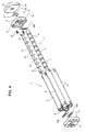
Figure 5 illustrates a variant of the module ofFigure 3 ; -
Figure 6 illustrates a second embodiment of the modular battery of the present invention, and -
Figure 7 illustrates a third embodiment of the modular battery of the present invention. - In
Figures 1 and2 , with 1 is indicated, as a whole, a modular battery capable of being installed on an electric or hybrid vehicle (not shown). - The modular battery 1 comprises a plurality of
battery modules 2 electrically connected in parallel with each other via anelectrical battery connector 3, which also serves as asupport body 2 of the battery modules themselves. - In particular, as illustrated in
Figures 3 and4 , eachbattery module 2 comprises n battery stacks orcells 4 electrically connected in series between them and grouped into k equal groups 5, which are housed inrespective casings 6 defined by cylindrical tubes arranged side by side in a compact configuration. - In the case of the example illustrated, the
cells 4 are cylindrical cells, preferably lithium-ion or nickel-cadmium batteries, and eachbattery module 2 comprises thirty-sixcells 4 grouped into four equal groups 5 housed in asmany casings 6, which are parallel to one another and sided two by two in order to give to thebattery module 2, a generally parallelepiped and compact shape. Thecasings 6 are arranged at a distance from each other to ensure, in use, effective heat dissipation from thecells 4. - With reference to
Figure 4 , thecasings 6 of eachbattery module 2 are locked in their positions by two retaining elements arranged in correspondence with respective ends of thebattery module 2 and defined by two caps 7 placed to close the open axial ends of thecasings 6 and connected to each other by the interposition of one or more tension rods (not shown). - Preferably, in order to facilitate the interchangeability of components and contain, therefore, production costs, the two caps 7 are equal to each other and are each provided, on the side facing the
casings 6, of a cavity 8 presenting four lobes, each of which is engaged in a removable way, by an end portion of arespective casing 6. - Centrally to the cavity 8, each cap 7 also presents an H-shaped through
opening 9, the function of which will be clarified below. - The four groups 5 are connected in series with each other by way of three metal plates, of which two
plates 10a are located inside the cavity 8 of one of the two caps 7, indicated below with 7a, and are oriented so that eachplate 10a electrically connects together a respective pair ofcells 4 with poles of opposite signs; athird plate 10b is arranged, instead, in the cavity 8 of the other cap 7, indicated below with 7b, and is oriented in such a way to electrically connect with each one of the two pairs ofcells 4 with poles of opposite signs. The pair ofcells 4 not engaged with theplate 10b defines the positive and negative poles of thebattery module 2. - As shown in
Figures 2 and4 , eachbattery module 2 comprises a respective moduleelectronic control unit 11, which has the function of monitoring and managing the operation of therespective battery module 2 independently from theother battery modules 2. Allelectronic units 11 of the modular battery 1 are electrically connected to a battery central electronic control unit (not shown), in turn connected to a electronic control unit of the vehicle (not shown). - In particular, each
electronic unit 11 is able to monitor the operation and charge state of therespective battery module 2 by measuring the temperature of thebattery module 2 itself, the voltage at the heads of each respective thirty-sixcells 4, and the current generated from thecells 4 themselves. - For this purpose, each
unit 11 comprises acontrol card 12, which engages theopening 9 of thecap 7b of therespective battery module 2 and is electrically connected to the pair ofcells 4 not engaged by theplate 10b by twosprings 13 compressed between thecontrol card 12 and thecells 4 themselves. - The cell voltage signals are relayed to the
control card 12 by fourflat cables 14, of which only one is illustrated in the attached figures, each of which is associated with a respective group 5, inserted inside therespective casing 6 and is provided with a plurality ofterminals 15 adapted to detect the voltage at the heads of eachcell 4 of the group 5 itself. Eachflat cable 14 is electrically connected to thecontrol card 12 by way of a respective externally protruding free-end portion of therespective casing 6 towards thecap 7b and firmly connected, for example by welding or a suitable connector, to thecontrol card 12 itself. Based on the measurement of the voltage of eachcell 4, thecontrol card 12 is configured to produce, where applicable, a passive balance of tension of theindividual cells 4. - Each
battery module 2 further comprises a current sensor (not shown), which is integrated in thecontrol card 12 to measure the electrical current supplied by therespective battery module 2, thereby permitting the monitoring of charge of thebattery module 2 itself, and a temperature sensor, which is also built into thecontrol card 12 to measure the operative temperature of thebattery module 2 and therefore allow to verify, in use, that the temperature of thebattery module 2 remains within predetermined operative values. - According to a variant, the temperature measurement is made at the level of the individual cells rather than at the level of the battery module, which are for this purpose provided with respective temperature sensors electrically connected to the
control card 12 via a flat cable similar to theflat cable 14. - Each
electronic unit 11 finally comprises a respective MEMS inertia switch, which is provided with an accelerometer, integrated into thecontrol card 12 and allowing disconnection of therespective battery module 2 in an automatic and independent way from theother battery modules 2 in the case where the modular battery 1 is subjected, in use, to mechanical stress of a determined value. - As shown in
Figures 1 ,2 and4 , eachbattery module 2 is provided with a moduleelectrical connector 16 carried by therespective control card 12 and provided with two power terminals connected to the positive and negative poles of therespective battery module 2, and signal terminals on which voltage, current and temperature signals of therespective battery module 2 are present or electrical signals obtained from these. Eachmodule connector 16 extends externally of therespective cap 7b through ahole 17 obtained in acover 18, which is attached, sealed in a non removable way to therespective cap 7b functioning as protection for thecontrol card 12. - As shown in
Figure 1 , thebattery connector 3 comprises aparallelepipedal body 19, which is defined by a flatrectangular wall 20 and by aside edge 21 defining, with thewall 20, acavity 22, within which are inserted, one alongside the other, the covers 18 of thebattery modules 2. - Inside the
cavity 22, thewall 20 holds, in addition, a plurality ofelectrical connectors 23, which are aligned and spaced one from the other so as to be each engaged with arespective module connector 16 for connecting in parallel between them and to anoutput power connector 24 arranged on theside edge 21, by appropriate electrical tracks, the power terminals of themodule connectors 16 of thebattery modules 2. - From the opposite side with respect to the
cavity 22, thebody 19 carries in a non removable way, a hollowlongitudinal appendage 25, which is part of thebattery connector 3 and houses a flatelectrical cable 26 adapted to electrically connect eachmodule connector 16 to anoutput signal connector 27 provided at one end of theappendix 25 from the same side of theoutput power connector 24. For this purpose, theflat cable 26 is provided with a plurality of terminals, each of which protrudes from theappendix 25 and extends through a respective opening cut in thewall 20, up to a correspondingelectrical connector 23 to electrically connect with theappropriate module connector 16. - Upon completion of that stated above, it should be noted that the number of
battery modules 2, of groups 5 andcells 4 of modular battery 1 inFigure 1 are only by way of example and may differ depending on the available space and/or the requested characteristics of the modular battery 1 in terms of electrical power and available space. - For example, to increase the module voltage it is necessary to increase the number of
cells 4 in series in eachbattery module 2, for example by increasing the number ofcells 4 of each of the four groups 5 and/or the number of groups 5, at the same number of cells per group. - As shown in
Figure 5 , the same result can be obtained by connecting in series twobattery modules battery modules 2 from the above example in order to get a doublelength battery module 2a. - In particular, the
battery module 28, which is the module that is connected to thebattery connector 3, is obtained by abattery module 2 simply eliminating, within therespective cap 7a, theserial connection plates 10a of thecells 4, and thebattery module 29 is obtained by abattery module 2 eliminating, within thecap 7b, theserial connection plate 10b of thecells 4; thecells 4 of thebattery module 28 are connected in series to thecell 4 of thebattery module 29 by electrical connectors, such as springs (not shown), placed through thecap 7a of thebattery module 28 and thecap 7b of thebattery module 29, whichcaps battery module 2a. -
Figure 6 shows amodular battery 1a obtained by connecting in parallel two battery modules of a type shown inFigure 1 so as to duplicate the suppliable electrical power. The two modular batteries 1 are rigidly connected, in a removable way, in correspondence to therespective appendages 25 so that allbattery modules 2 of themodular battery 1a are coplanar and confer, in this way, a compact shape and a relatively small encumbrance to themodular battery 1a itself. - Finally, in
Figure 7 is shown amodular battery 1b, which differs from the modular battery 1 offigure 1 for the number and arrangement of thebattery modules 2, which, in this case, are four and are sided in pairs. Consequently, thewall 20 and theappendix 25 of thebody 19 of thebattery connector 3 present a generally square shape; and finally, in this case, the output power and the output signal from thebattery module 2 are combined into asingle output connector 30 carried by theappendix 25. - From the foregoing, it is clear that the
modular battery - From the structural point of view, in fact, we saw how the architecture of the
battery module 2 and, especially, the presence of interchangeable and interfaceable components, such ascaps casings 6 in therespective battery modules 2 and ofbattery modules 2 in the modular battery 1 allows effective dissipation of heat produced by thecells 4, thereby increasing efficiency compared to conventional batteries. - From a managing perspective, it should be noted that the presence of a local
electronic unit 11 for eachbattery module 2 achieves a control of modular battery 1 at the module level with the advantage of considerably simplifying the wiring and the control unit of the modular battery 1, of a better accuracy in determining the charge state and functioning of thebattery modules 2 and of the entire modular battery 1, and greater system reliability due also to the fact of being able to deactivate, if necessary, one ormore battery modules 2 in a totally independent way one from the other and without affecting the operation of theremaining battery modules 2.
Claims (11)
- A modular battery (1; 1°; 1b) comprising a plurality of battery modules (2; 2a) and a battery electrical connector (3) for electrically connecting in parallel the battery modules (2; 2a); each battery module (2; 2a) comprising n battery stacks or cells (4) connected in series and being characterized by further comprising a module electronic unit (11) configured to control and manage the respective battery module (2; 2a) independently from the other battery modules (2; 2a).
- The modular battery according to claim 1, wherein the cells (4) in each battery module (2; 2a) are grouped into k equal groups (5); the battery module (2; 2a) comprising k casings (6), each of which houses a respective one of said groups (5), and two retaining elements (7) arranged at respective ends of the battery module (2; 2a) to mutually retain the casings (6).
- The modular battery according to claim 2, wherein said casings (6) are cylindrical tubes arranged parallel to each other, and said retaining elements (7) are defined by two caps (7a, 7b), each of which is arranged to close open axial ends of the casings (6) at a respective end of the battery module (2; 2a).
- The modular battery according to claim 3, comprising, for each battery module (2; 2a), electrical connection means (10a, 10b, 13) to electrically connect the cells (4) in series and to the respective electronic module unit (11); said electrical connection means (10a, 10b, 13) being adapted to be arranged between the caps (7a, 7b) and the battery cells (4) facing the caps (7a, 7b).
- The modular battery according to claim 3 or 4, in which each electronic unit (11) comprises a management board (12) arranged close to one (7b) of the two caps (7a, 7b) of the respective battery module (2; 2a) and provided with an inertial switch operable to disconnect the respective battery module (2; 2a) autonomously and independently from the other battery modules (2; 2a).
- The modular battery according to claim 5, in which the other (7b) of the two caps (7a, 7b) in each battery module (2, 2a) is configured to allow the battery module (2; 2a) to be electrically connected in series to another battery module (2; 2a).
- The modular battery according to any of the preceding claims, in which each battery module (2; 2a) comprises voltage sensing means (15) operable to measure a voltage across each battery cell (4) of the battery module (2; 2a).
- The modular battery according to any of the preceding claims, in which each battery module (2; 2a) comprises temperature sensing means operable to measure an operating temperature of either the battery module (2; 2a) or the individual battery cells (4) in the battery module (2; 2a).
- The modular battery according to any of the preceding claims, in which each battery module (2; 2a) comprises current sensing means to measure the electrical current supplied from the battery module (2; 2a).
- The modular battery according to one of claims from 5 to 9, in which each battery module (2; 2a) is provided with a respective module electrical connector (16) carried by the management board (12) to electrically connect the battery module (2; 2a) to said battery electrical connector (3).
- The modular battery according to claim 10, wherein the battery electrical connector (3) is further configured to rigidly support the battery modules (2; 2a).
Priority Applications (1)
| Application Number | Priority Date | Filing Date | Title |
|---|---|---|---|
| EP11425132.5A EP2523246B1 (en) | 2011-05-11 | 2011-05-11 | Modular battery for electric or hybrid vehicles |
Applications Claiming Priority (1)
| Application Number | Priority Date | Filing Date | Title |
|---|---|---|---|
| EP11425132.5A EP2523246B1 (en) | 2011-05-11 | 2011-05-11 | Modular battery for electric or hybrid vehicles |
Publications (2)
| Publication Number | Publication Date |
|---|---|
| EP2523246A1 true EP2523246A1 (en) | 2012-11-14 |
| EP2523246B1 EP2523246B1 (en) | 2017-03-08 |
Family
ID=44503663
Family Applications (1)
| Application Number | Title | Priority Date | Filing Date |
|---|---|---|---|
| EP11425132.5A Not-in-force EP2523246B1 (en) | 2011-05-11 | 2011-05-11 | Modular battery for electric or hybrid vehicles |
Country Status (1)
| Country | Link |
|---|---|
| EP (1) | EP2523246B1 (en) |
Cited By (12)
| Publication number | Priority date | Publication date | Assignee | Title |
|---|---|---|---|---|
| WO2015075460A1 (en) * | 2013-11-20 | 2015-05-28 | Vantage Power Limited | Battery pack |
| DE102014101335A1 (en) | 2014-02-04 | 2015-08-06 | Dr. Ing. H.C. F. Porsche Aktiengesellschaft | Battery unit comprising at least a first battery module and at least a second battery module in a battery housing |
| US9960396B2 (en) | 2013-09-24 | 2018-05-01 | Artisan Vehicle Systems Inc. | Module backbone system |
| US10063069B1 (en) | 2014-05-23 | 2018-08-28 | Artisan Vehicle Systems Inc. | Module maintenance system |
| US10457148B2 (en) | 2017-02-24 | 2019-10-29 | Epic Battery Inc. | Solar car |
| CN110571399A (en) * | 2018-06-06 | 2019-12-13 | 罗伯特·博世有限公司 | Battery module |
| US10587221B2 (en) | 2017-04-03 | 2020-03-10 | Epic Battery Inc. | Modular solar battery |
| US20200168861A1 (en) * | 2018-11-05 | 2020-05-28 | Green Light Innovations | Housing assembly for use with energy storage systems |
| EP3896775A4 (en) * | 2019-07-03 | 2022-03-30 | LG Energy Solution, Ltd. | BATTERY PACK AND ENERGY STORAGE DEVICE COMPRISING THE SAME |
| US11302980B2 (en) | 2018-02-16 | 2022-04-12 | Toyota Material Handling Manufacturing Sweden Ab | Arrangement for assembling rechargeable batteries into a battery module and a battery module |
| US11489082B2 (en) | 2019-07-30 | 2022-11-01 | Epic Battery Inc. | Durable solar panels |
| WO2023071757A1 (en) * | 2021-10-29 | 2023-05-04 | 比亚迪股份有限公司 | Sampling apparatus, battery management system, and vehicle |
Families Citing this family (1)
| Publication number | Priority date | Publication date | Assignee | Title |
|---|---|---|---|---|
| EP4607669A1 (en) * | 2024-02-26 | 2025-08-27 | Fachhochschule Dortmund, Körperschaft des öffentlichen Rechts | Electrical energy store |
Citations (4)
| Publication number | Priority date | Publication date | Assignee | Title |
|---|---|---|---|---|
| US20080118819A1 (en) * | 2006-11-17 | 2008-05-22 | Paul Gamboa | Modular battery system |
| US20100141208A1 (en) * | 2008-02-12 | 2010-06-10 | Deal Larry L | Energy Storage Module |
| EP2207221A1 (en) * | 2009-01-09 | 2010-07-14 | Electrochem Solutions, Inc. | Modular battery pack |
| WO2011008736A2 (en) * | 2009-07-14 | 2011-01-20 | Parker-Hannifan Corporation | Integrated battery packaging, interconnect, and charge management system |
-
2011
- 2011-05-11 EP EP11425132.5A patent/EP2523246B1/en not_active Not-in-force
Patent Citations (4)
| Publication number | Priority date | Publication date | Assignee | Title |
|---|---|---|---|---|
| US20080118819A1 (en) * | 2006-11-17 | 2008-05-22 | Paul Gamboa | Modular battery system |
| US20100141208A1 (en) * | 2008-02-12 | 2010-06-10 | Deal Larry L | Energy Storage Module |
| EP2207221A1 (en) * | 2009-01-09 | 2010-07-14 | Electrochem Solutions, Inc. | Modular battery pack |
| WO2011008736A2 (en) * | 2009-07-14 | 2011-01-20 | Parker-Hannifan Corporation | Integrated battery packaging, interconnect, and charge management system |
Cited By (18)
| Publication number | Priority date | Publication date | Assignee | Title |
|---|---|---|---|---|
| US11025073B2 (en) | 2013-09-24 | 2021-06-01 | Artisan Vehicle Systems, Inc. | Module maintenance system |
| US9960396B2 (en) | 2013-09-24 | 2018-05-01 | Artisan Vehicle Systems Inc. | Module backbone system |
| US11342624B2 (en) | 2013-09-24 | 2022-05-24 | Artisan Vehicle Systems Inc. | Module backbone system |
| US10593919B2 (en) | 2013-09-24 | 2020-03-17 | Artisan Vehicle Systems Inc. | Module backbone system |
| GB2520929A (en) * | 2013-11-20 | 2015-06-10 | Vantage Power Ltd | Battery Pack |
| WO2015075460A1 (en) * | 2013-11-20 | 2015-05-28 | Vantage Power Limited | Battery pack |
| DE102014101335A1 (en) | 2014-02-04 | 2015-08-06 | Dr. Ing. H.C. F. Porsche Aktiengesellschaft | Battery unit comprising at least a first battery module and at least a second battery module in a battery housing |
| US9831478B2 (en) | 2014-02-04 | 2017-11-28 | Dr. Ing. H.C.F. Porsche Aktiengesellschaft | Battery unit having at least one first battery module and at least one second battery module in a battery housing |
| US10063069B1 (en) | 2014-05-23 | 2018-08-28 | Artisan Vehicle Systems Inc. | Module maintenance system |
| US10457148B2 (en) | 2017-02-24 | 2019-10-29 | Epic Battery Inc. | Solar car |
| US10587221B2 (en) | 2017-04-03 | 2020-03-10 | Epic Battery Inc. | Modular solar battery |
| US11302980B2 (en) | 2018-02-16 | 2022-04-12 | Toyota Material Handling Manufacturing Sweden Ab | Arrangement for assembling rechargeable batteries into a battery module and a battery module |
| CN110571399A (en) * | 2018-06-06 | 2019-12-13 | 罗伯特·博世有限公司 | Battery module |
| US20200168861A1 (en) * | 2018-11-05 | 2020-05-28 | Green Light Innovations | Housing assembly for use with energy storage systems |
| EP3896775A4 (en) * | 2019-07-03 | 2022-03-30 | LG Energy Solution, Ltd. | BATTERY PACK AND ENERGY STORAGE DEVICE COMPRISING THE SAME |
| AU2020300329B2 (en) * | 2019-07-03 | 2025-09-04 | Lg Energy Solution, Ltd. | Battery pack and power storage device comprising same |
| US11489082B2 (en) | 2019-07-30 | 2022-11-01 | Epic Battery Inc. | Durable solar panels |
| WO2023071757A1 (en) * | 2021-10-29 | 2023-05-04 | 比亚迪股份有限公司 | Sampling apparatus, battery management system, and vehicle |
Also Published As
| Publication number | Publication date |
|---|---|
| EP2523246B1 (en) | 2017-03-08 |
Similar Documents
| Publication | Publication Date | Title |
|---|---|---|
| EP2523246B1 (en) | Modular battery for electric or hybrid vehicles | |
| US11539087B2 (en) | Vehicle energy-storage systems | |
| CN103698580B (en) | Cell voltage, temperature acquisition system | |
| CN102640321A (en) | Battery module and battery system | |
| CN100511824C (en) | Component for measuring cell voltage and temperature in battery pack | |
| US20150023392A1 (en) | Battery pack | |
| US12300792B2 (en) | Battery module having improved assemblability and battery pack including the same | |
| KR20110112900A (en) | Battery module including a sensing member of a novel structure | |
| KR101561123B1 (en) | Battery Module Having Assemblable Bus Bar for Voltage Sensing | |
| CN102306717A (en) | Lithium ion power battery pack for electric automobile and manufacturing method of lithium ion power battery pack | |
| WO2023078035A1 (en) | Battery pack and vehicle | |
| KR102879273B1 (en) | Batteries and electrical devices | |
| US20100141208A1 (en) | Energy Storage Module | |
| US20120189887A1 (en) | Electrical energy storage device made of flat cells and frame elements with a supply channel | |
| US9741991B2 (en) | Integrated voltage sense and bus bar system and method for vehicles having a traction battery | |
| CN113258157B (en) | Battery and electric device | |
| JP2010097723A (en) | Battery pack | |
| EP2953185A1 (en) | Multifunctional battery cover and power battery pack thereof | |
| KR20210112650A (en) | Battery module and battery pack including the same | |
| KR20120120675A (en) | Battery having Sensing Assembly Structure for Processing Signal of Cell | |
| JP5915460B2 (en) | Temperature sensor mounting structure and wiring module manufacturing method | |
| CN217589299U (en) | Wire harness board assembly and battery device | |
| CN117458076B (en) | Bracket and electric connection assembly | |
| CN218677504U (en) | Signal sampling assembly for battery module and battery module | |
| CN220628126U (en) | Cell components, battery modules and battery packs |
Legal Events
| Date | Code | Title | Description |
|---|---|---|---|
| PUAI | Public reference made under article 153(3) epc to a published international application that has entered the european phase |
Free format text: ORIGINAL CODE: 0009012 |
|
| AK | Designated contracting states |
Kind code of ref document: A1 Designated state(s): AL AT BE BG CH CY CZ DE DK EE ES FI FR GB GR HR HU IE IS IT LI LT LU LV MC MK MT NL NO PL PT RO RS SE SI SK SM TR |
|
| AX | Request for extension of the european patent |
Extension state: BA ME |
|
| 17P | Request for examination filed |
Effective date: 20130430 |
|
| REG | Reference to a national code |
Ref country code: DE Ref legal event code: R079 Ref document number: 602011035665 Country of ref document: DE Free format text: PREVIOUS MAIN CLASS: H01M0010052500 Ipc: H01M0002020000 |
|
| GRAP | Despatch of communication of intention to grant a patent |
Free format text: ORIGINAL CODE: EPIDOSNIGR1 |
|
| INTG | Intention to grant announced |
Effective date: 20160930 |
|
| RIC1 | Information provided on ipc code assigned before grant |
Ipc: H01M 10/48 20060101ALI20160919BHEP Ipc: H01M 2/10 20060101ALI20160919BHEP Ipc: H01M 10/34 20060101ALN20160919BHEP Ipc: H01M 10/0525 20100101ALN20160919BHEP Ipc: H01M 2/02 20060101AFI20160919BHEP Ipc: H01M 2/20 20060101ALI20160919BHEP |
|
| GRAS | Grant fee paid |
Free format text: ORIGINAL CODE: EPIDOSNIGR3 |
|
| GRAA | (expected) grant |
Free format text: ORIGINAL CODE: 0009210 |
|
| AK | Designated contracting states |
Kind code of ref document: B1 Designated state(s): AL AT BE BG CH CY CZ DE DK EE ES FI FR GB GR HR HU IE IS IT LI LT LU LV MC MK MT NL NO PL PT RO RS SE SI SK SM TR |
|
| REG | Reference to a national code |
Ref country code: GB Ref legal event code: FG4D |
|
| REG | Reference to a national code |
Ref country code: CH Ref legal event code: EP Ref country code: AT Ref legal event code: REF Ref document number: 874260 Country of ref document: AT Kind code of ref document: T Effective date: 20170315 |
|
| REG | Reference to a national code |
Ref country code: IE Ref legal event code: FG4D |
|
| REG | Reference to a national code |
Ref country code: DE Ref legal event code: R096 Ref document number: 602011035665 Country of ref document: DE |
|
| REG | Reference to a national code |
Ref country code: FR Ref legal event code: PLFP Year of fee payment: 7 |
|
| REG | Reference to a national code |
Ref country code: LT Ref legal event code: MG4D |
|
| REG | Reference to a national code |
Ref country code: NL Ref legal event code: MP Effective date: 20170308 |
|
| PG25 | Lapsed in a contracting state [announced via postgrant information from national office to epo] |
Ref country code: GR Free format text: LAPSE BECAUSE OF FAILURE TO SUBMIT A TRANSLATION OF THE DESCRIPTION OR TO PAY THE FEE WITHIN THE PRESCRIBED TIME-LIMIT Effective date: 20170609 Ref country code: FI Free format text: LAPSE BECAUSE OF FAILURE TO SUBMIT A TRANSLATION OF THE DESCRIPTION OR TO PAY THE FEE WITHIN THE PRESCRIBED TIME-LIMIT Effective date: 20170308 Ref country code: HR Free format text: LAPSE BECAUSE OF FAILURE TO SUBMIT A TRANSLATION OF THE DESCRIPTION OR TO PAY THE FEE WITHIN THE PRESCRIBED TIME-LIMIT Effective date: 20170308 Ref country code: NO Free format text: LAPSE BECAUSE OF FAILURE TO SUBMIT A TRANSLATION OF THE DESCRIPTION OR TO PAY THE FEE WITHIN THE PRESCRIBED TIME-LIMIT Effective date: 20170608 Ref country code: LT Free format text: LAPSE BECAUSE OF FAILURE TO SUBMIT A TRANSLATION OF THE DESCRIPTION OR TO PAY THE FEE WITHIN THE PRESCRIBED TIME-LIMIT Effective date: 20170308 |
|
| REG | Reference to a national code |
Ref country code: AT Ref legal event code: MK05 Ref document number: 874260 Country of ref document: AT Kind code of ref document: T Effective date: 20170308 |
|
| PG25 | Lapsed in a contracting state [announced via postgrant information from national office to epo] |
Ref country code: SE Free format text: LAPSE BECAUSE OF FAILURE TO SUBMIT A TRANSLATION OF THE DESCRIPTION OR TO PAY THE FEE WITHIN THE PRESCRIBED TIME-LIMIT Effective date: 20170308 Ref country code: ES Free format text: LAPSE BECAUSE OF FAILURE TO SUBMIT A TRANSLATION OF THE DESCRIPTION OR TO PAY THE FEE WITHIN THE PRESCRIBED TIME-LIMIT Effective date: 20170308 Ref country code: BG Free format text: LAPSE BECAUSE OF FAILURE TO SUBMIT A TRANSLATION OF THE DESCRIPTION OR TO PAY THE FEE WITHIN THE PRESCRIBED TIME-LIMIT Effective date: 20170608 Ref country code: LV Free format text: LAPSE BECAUSE OF FAILURE TO SUBMIT A TRANSLATION OF THE DESCRIPTION OR TO PAY THE FEE WITHIN THE PRESCRIBED TIME-LIMIT Effective date: 20170308 Ref country code: RS Free format text: LAPSE BECAUSE OF FAILURE TO SUBMIT A TRANSLATION OF THE DESCRIPTION OR TO PAY THE FEE WITHIN THE PRESCRIBED TIME-LIMIT Effective date: 20170308 Ref country code: LU Free format text: LAPSE BECAUSE OF NON-PAYMENT OF DUE FEES Effective date: 20170531 |
|
| PG25 | Lapsed in a contracting state [announced via postgrant information from national office to epo] |
Ref country code: NL Free format text: LAPSE BECAUSE OF FAILURE TO SUBMIT A TRANSLATION OF THE DESCRIPTION OR TO PAY THE FEE WITHIN THE PRESCRIBED TIME-LIMIT Effective date: 20170308 |
|
| PG25 | Lapsed in a contracting state [announced via postgrant information from national office to epo] |
Ref country code: EE Free format text: LAPSE BECAUSE OF FAILURE TO SUBMIT A TRANSLATION OF THE DESCRIPTION OR TO PAY THE FEE WITHIN THE PRESCRIBED TIME-LIMIT Effective date: 20170308 Ref country code: CZ Free format text: LAPSE BECAUSE OF FAILURE TO SUBMIT A TRANSLATION OF THE DESCRIPTION OR TO PAY THE FEE WITHIN THE PRESCRIBED TIME-LIMIT Effective date: 20170308 Ref country code: SK Free format text: LAPSE BECAUSE OF FAILURE TO SUBMIT A TRANSLATION OF THE DESCRIPTION OR TO PAY THE FEE WITHIN THE PRESCRIBED TIME-LIMIT Effective date: 20170308 Ref country code: RO Free format text: LAPSE BECAUSE OF FAILURE TO SUBMIT A TRANSLATION OF THE DESCRIPTION OR TO PAY THE FEE WITHIN THE PRESCRIBED TIME-LIMIT Effective date: 20170308 Ref country code: AT Free format text: LAPSE BECAUSE OF FAILURE TO SUBMIT A TRANSLATION OF THE DESCRIPTION OR TO PAY THE FEE WITHIN THE PRESCRIBED TIME-LIMIT Effective date: 20170308 |
|
| PG25 | Lapsed in a contracting state [announced via postgrant information from national office to epo] |
Ref country code: SM Free format text: LAPSE BECAUSE OF FAILURE TO SUBMIT A TRANSLATION OF THE DESCRIPTION OR TO PAY THE FEE WITHIN THE PRESCRIBED TIME-LIMIT Effective date: 20170308 Ref country code: PL Free format text: LAPSE BECAUSE OF FAILURE TO SUBMIT A TRANSLATION OF THE DESCRIPTION OR TO PAY THE FEE WITHIN THE PRESCRIBED TIME-LIMIT Effective date: 20170308 Ref country code: PT Free format text: LAPSE BECAUSE OF FAILURE TO SUBMIT A TRANSLATION OF THE DESCRIPTION OR TO PAY THE FEE WITHIN THE PRESCRIBED TIME-LIMIT Effective date: 20170710 Ref country code: IS Free format text: LAPSE BECAUSE OF FAILURE TO SUBMIT A TRANSLATION OF THE DESCRIPTION OR TO PAY THE FEE WITHIN THE PRESCRIBED TIME-LIMIT Effective date: 20170708 |
|
| REG | Reference to a national code |
Ref country code: DE Ref legal event code: R097 Ref document number: 602011035665 Country of ref document: DE |
|
| REG | Reference to a national code |
Ref country code: CH Ref legal event code: PL |
|
| PLBE | No opposition filed within time limit |
Free format text: ORIGINAL CODE: 0009261 |
|
| STAA | Information on the status of an ep patent application or granted ep patent |
Free format text: STATUS: NO OPPOSITION FILED WITHIN TIME LIMIT |
|
| PG25 | Lapsed in a contracting state [announced via postgrant information from national office to epo] |
Ref country code: MC Free format text: LAPSE BECAUSE OF FAILURE TO SUBMIT A TRANSLATION OF THE DESCRIPTION OR TO PAY THE FEE WITHIN THE PRESCRIBED TIME-LIMIT Effective date: 20170308 Ref country code: DK Free format text: LAPSE BECAUSE OF FAILURE TO SUBMIT A TRANSLATION OF THE DESCRIPTION OR TO PAY THE FEE WITHIN THE PRESCRIBED TIME-LIMIT Effective date: 20170308 |
|
| 26N | No opposition filed |
Effective date: 20171211 |
|
| REG | Reference to a national code |
Ref country code: IE Ref legal event code: MM4A |
|
| GBPC | Gb: european patent ceased through non-payment of renewal fee |
Effective date: 20170608 |
|
| PG25 | Lapsed in a contracting state [announced via postgrant information from national office to epo] |
Ref country code: LI Free format text: LAPSE BECAUSE OF NON-PAYMENT OF DUE FEES Effective date: 20170531 Ref country code: SI Free format text: LAPSE BECAUSE OF FAILURE TO SUBMIT A TRANSLATION OF THE DESCRIPTION OR TO PAY THE FEE WITHIN THE PRESCRIBED TIME-LIMIT Effective date: 20170308 Ref country code: CH Free format text: LAPSE BECAUSE OF NON-PAYMENT OF DUE FEES Effective date: 20170531 |
|
| PG25 | Lapsed in a contracting state [announced via postgrant information from national office to epo] |
Ref country code: LU Free format text: LAPSE BECAUSE OF NON-PAYMENT OF DUE FEES Effective date: 20170511 |
|
| REG | Reference to a national code |
Ref country code: BE Ref legal event code: MM Effective date: 20170531 |
|
| PG25 | Lapsed in a contracting state [announced via postgrant information from national office to epo] |
Ref country code: IE Free format text: LAPSE BECAUSE OF NON-PAYMENT OF DUE FEES Effective date: 20170511 Ref country code: GB Free format text: LAPSE BECAUSE OF NON-PAYMENT OF DUE FEES Effective date: 20170608 |
|
| REG | Reference to a national code |
Ref country code: FR Ref legal event code: PLFP Year of fee payment: 8 |
|
| PG25 | Lapsed in a contracting state [announced via postgrant information from national office to epo] |
Ref country code: BE Free format text: LAPSE BECAUSE OF NON-PAYMENT OF DUE FEES Effective date: 20170531 |
|
| PG25 | Lapsed in a contracting state [announced via postgrant information from national office to epo] |
Ref country code: MT Free format text: LAPSE BECAUSE OF NON-PAYMENT OF DUE FEES Effective date: 20170511 |
|
| PG25 | Lapsed in a contracting state [announced via postgrant information from national office to epo] |
Ref country code: HU Free format text: LAPSE BECAUSE OF FAILURE TO SUBMIT A TRANSLATION OF THE DESCRIPTION OR TO PAY THE FEE WITHIN THE PRESCRIBED TIME-LIMIT; INVALID AB INITIO Effective date: 20110511 |
|
| PG25 | Lapsed in a contracting state [announced via postgrant information from national office to epo] |
Ref country code: CY Free format text: LAPSE BECAUSE OF NON-PAYMENT OF DUE FEES Effective date: 20170308 |
|
| PG25 | Lapsed in a contracting state [announced via postgrant information from national office to epo] |
Ref country code: MK Free format text: LAPSE BECAUSE OF FAILURE TO SUBMIT A TRANSLATION OF THE DESCRIPTION OR TO PAY THE FEE WITHIN THE PRESCRIBED TIME-LIMIT Effective date: 20170308 |
|
| PG25 | Lapsed in a contracting state [announced via postgrant information from national office to epo] |
Ref country code: TR Free format text: LAPSE BECAUSE OF FAILURE TO SUBMIT A TRANSLATION OF THE DESCRIPTION OR TO PAY THE FEE WITHIN THE PRESCRIBED TIME-LIMIT Effective date: 20170308 |
|
| PG25 | Lapsed in a contracting state [announced via postgrant information from national office to epo] |
Ref country code: AL Free format text: LAPSE BECAUSE OF FAILURE TO SUBMIT A TRANSLATION OF THE DESCRIPTION OR TO PAY THE FEE WITHIN THE PRESCRIBED TIME-LIMIT Effective date: 20170308 |
|
| REG | Reference to a national code |
Ref country code: DE Ref legal event code: R079 Ref document number: 602011035665 Country of ref document: DE Free format text: PREVIOUS MAIN CLASS: H01M0002020000 Ipc: H01M0050100000 |
|
| PGFP | Annual fee paid to national office [announced via postgrant information from national office to epo] |
Ref country code: DE Payment date: 20240418 Year of fee payment: 14 |
|
| PGFP | Annual fee paid to national office [announced via postgrant information from national office to epo] |
Ref country code: IT Payment date: 20240418 Year of fee payment: 14 Ref country code: FR Payment date: 20240418 Year of fee payment: 14 |
|
| REG | Reference to a national code |
Ref country code: DE Ref legal event code: R119 Ref document number: 602011035665 Country of ref document: DE |
|
| PG25 | Lapsed in a contracting state [announced via postgrant information from national office to epo] |
Ref country code: DE Free format text: LAPSE BECAUSE OF NON-PAYMENT OF DUE FEES Effective date: 20251202 |
|
| PG25 | Lapsed in a contracting state [announced via postgrant information from national office to epo] |
Ref country code: IT Free format text: LAPSE BECAUSE OF NON-PAYMENT OF DUE FEES Effective date: 20250511 |
|
| PG25 | Lapsed in a contracting state [announced via postgrant information from national office to epo] |
Ref country code: FR Free format text: LAPSE BECAUSE OF NON-PAYMENT OF DUE FEES Effective date: 20250531 |