EP2523167A1 - Methods and devices for displaying three-dimensional landscapes - Google Patents
Methods and devices for displaying three-dimensional landscapes Download PDFInfo
- Publication number
- EP2523167A1 EP2523167A1 EP11165443A EP11165443A EP2523167A1 EP 2523167 A1 EP2523167 A1 EP 2523167A1 EP 11165443 A EP11165443 A EP 11165443A EP 11165443 A EP11165443 A EP 11165443A EP 2523167 A1 EP2523167 A1 EP 2523167A1
- Authority
- EP
- European Patent Office
- Prior art keywords
- river
- landscape
- representation
- vertices
- altitude
- Prior art date
- Legal status (The legal status is an assumption and is not a legal conclusion. Google has not performed a legal analysis and makes no representation as to the accuracy of the status listed.)
- Granted
Links
Images







Classifications
-
- G—PHYSICS
- G06—COMPUTING OR CALCULATING; COUNTING
- G06T—IMAGE DATA PROCESSING OR GENERATION, IN GENERAL
- G06T17/00—Three-dimensional [3D] modelling for computer graphics
- G06T17/05—Geographic models
-
- G—PHYSICS
- G01—MEASURING; TESTING
- G01C—MEASURING DISTANCES, LEVELS OR BEARINGS; SURVEYING; NAVIGATION; GYROSCOPIC INSTRUMENTS; PHOTOGRAMMETRY OR VIDEOGRAMMETRY
- G01C21/00—Navigation; Navigational instruments not provided for in groups G01C1/00 - G01C19/00
- G01C21/26—Navigation; Navigational instruments not provided for in groups G01C1/00 - G01C19/00 specially adapted for navigation in a road network
- G01C21/34—Route searching; Route guidance
- G01C21/36—Input/output arrangements for on-board computers
- G01C21/3626—Details of the output of route guidance instructions
- G01C21/3635—Guidance using 3D or perspective road maps
- G01C21/3638—Guidance using 3D or perspective road maps including 3D objects and buildings
-
- G—PHYSICS
- G06—COMPUTING OR CALCULATING; COUNTING
- G06T—IMAGE DATA PROCESSING OR GENERATION, IN GENERAL
- G06T17/00—Three-dimensional [3D] modelling for computer graphics
- G06T17/20—Finite element generation, e.g. wire-frame surface description, tesselation
Definitions
- This invention relates to methods and devices for displaying three-dimensional landscapes, for example on displays of navigation devices.
- Navigation devices are nowadays used to guide a user to a destination.
- the position of the navigation device is shown with its surroundings. This may be done by showing the position on a map.
- a three-dimensional perspective is used, i.e. the landscape surrounding the navigation device is displayed in a three-dimensional manner.
- a triangulated irregular network is a digital data structure used for the representation of a three-dimensional surface and is made up of irregular distributed vertices, also referred to as nodes or mass points, and lines with three-dimensional coordinates, for example x, y, z, that are arranged in a network of non-overlapping triangles.
- TINs may for example be derived from altitude data of a rasterized digital altitude model.
- a TIN therefore comprises a triangular network of vertices with associated coordinates in three dimensions as mentioned above which are connected by edges to form a triangular tessellation. Three-dimensional visualisations can then be created by rendering of the triangular facets. In regions where there is little variation in surface height, i.e. altitude, the vertices may be widely spaced, whereas in areas of more intense variation of the altitude the vertices' density may be increased.
- the altitude is interpolated, usually in a linear manner (for example, joining vertices by edges as described above constitutes such a linear interpolation).
- this may lead to unnatural looking results. For example, if a river runs between two vertices, the river may be displayed with a slope in a direction perpendicular to its flowing direction, which does not exist for real rivers. Similar problems may occur with other landscape elements.
- a method for displaying three-dimensional landscapes comprising:
- the predetermined landscape elements may for example comprise rivers, lakes, oceans and/or buildings.
- the river may for example be represented by a polygon.
- the river may be divided into frames, and the altitude of each frame may be limited to the altitude of the previous frame. In this way, it may be ensured that the river runs downwards.
- bisecting lines may be determined and their intersections with the polygon may be used as vertices for determining the altitudes of the polygon by interpolating between the vertices. In this way, it may be prevented that a river exhibits a slope in a direction not parallel to the flowing direction of the river.
- a line representation of the river may be provided, for example a line representation running along a middle line of the river.
- the vector may run in the middle of the aforementioned frames in a flowing direction of the river.
- Direction changes may be identified, and endpoints/starting points of lines at such direction changes may be split, and a triangle or other plateau may be inserted at the direction change.
- an altitude of an area covered by the ocean may be set to sea level.
- an average level of the lake is provided.
- a weighted average may be provided, where a center of the lake may have a higher weight than a boarder of the lake.
- the altitude of the lake may then be set to the determined average level.
- the identified landscape element may be a building, and the ground for the building may be levelled, for example to a lowest altitude according to the altitude data.
- additional vertices and therefore e.g. additional triangles may be inserted as border areas between the individually calculated representation and the remaining altitude data.
- a device comprising a storage storing altitude data comprising a plurality of vertices, and a processor which is configured to identify predetermined landscape elements in the landscape to be displayed and to individually calculate a representation of the identified at least one predetermined landscape element.
- the device comprises a display, and the processor is further configured to cause the display to display a landscape based on the altitude data and the individually calculated representation of the at least one predetermined landscape element.
- the device may be configured to implement any of the methods described above, for example by programming the processor accordingly.
- the device may be a navigation device.
- Navigation device 10 comprises a display 11, a processor 12, a GPS (Global Positioning System) unit 13 and a storage 14.
- Processor 12 may be any suitable programmable microprocessor or any other device with processing capabilities, or may also comprise a plurality of sub-processors.
- Processor 12 executes programs for example stored in storage 14 to provide functionalities of navigation device 10. Any conventional functionality of navigation devices may be provided, in particular calculating routes to a desired destination and displaying a current position on display 11, wherein the current position may for example be obtained via GPS unit 13.
- storage 14 may comprise any necessary map data 16 for navigation, similar to conventional navigation devices.
- Map data 16 may for example give geographical information about the landscape to be displayed, for example the position of elements like streets, buildings, rivers, forests, etc.
- Navigation device 10 in particular is capable of showing the surroundings of the navigation device and therefore of a user of a navigation device, for example the surroundings of a car incorporating the navigation device, or also other scenery, for example a representation of a landscape around a destination of a route, in a three-dimensional manner on display 11.
- triangulated irregular network (TIN) data 15 comprises a plurality of vertices is shown.
- the coordinates of a plurality of vertices are stored including their altitude (height) coordinate, and these vertices may then be joint by edges to form triangles which then may be rendered.
- TIN data 15 also other altitude data comprising a plurality of vertices, for example a regular triangulated network where the vertices are equidistantly spaced, may be provided.
- Fig. 1 shows only some possible components of a navigation device, and other components like a user interface or an audio output are also possible.
- the application of the present invention is not restricted to navigation devices, but may also be employed in other cases, where three-dimensional landscapes are to be displayed on a display.
- Various implementations of the above-mentioned identifying and displaying of predetermined landscape types will be explained in the following with reference to Figs. 2 to 11 .
- FIG. 2 a flow chart representing a method according to an embodiment is shown.
- the methods of Fig. 2 may be implemented in the device of Fig. 1 , for example by programming processor 12 accordingly, but may also be implemented independently therefrom.
- TIN data is provided, for example by providing TIN data in a storage like storage 14. Furthermore, at 20 map data like map data 16 of Fig. 1 is provided.
- predetermined landscape types in a landscape to be displayed are identified, for example based on the map data.
- Predetermined landscape types may be types which, when displayed on TIN data alone, lead potentially to unrealistic results.
- Such landscape types may for example comprise rivers, lakes, oceans or buildings.
- 3D representations of the identified landscape types are calculated which may deviate from a representation based on the triangulated irregular network and may lead to a more realistic representation.
- the actions described with reference to 21 and 22 may for example be performed by processor 12 of Fig. 1 .
- the landscape is displayed based on the TIN data and based on the calculated representation of the identified landscape types.
- the calculated representation is used, whereas for the remaining landscape the TIN data is used for displaying.
- a method for handling a river in some embodiments of the present invention will be described.
- the method may for example be implemented in the navigation device of Fig. 1 and is an example for the implementation of the actions described with reference to 21 and 22 in Fig. 2 in case the predetermined landscape type is a river.
- the embodiment of Fig. 3 may also be implemented independently from the embodiments of Figs. 1 and 2 .
- FIG. 3 a flow chart representing a method according to an embodiment is shown.
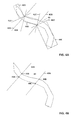
- Figs. 4A and 4B illustrative, non-limiting diagrams illustrating the method of Fig. 3 further are shown.
- a river is identified in a landscape to be displayed.
- the river for example in a map database, may for example be represented by a polygon approximating the outline of the river.
- a polygon 43 is shown representing a river.
- the river is then divided into oriented frames, which in particular may be rectangles oriented according to a (main) direction of the river in the area covered by the frames.
- oriented frames which in particular may be rectangles oriented according to a (main) direction of the river in the area covered by the frames.
- FIGs. 4A frames 40A, 40B and 40C are shown.
- a criterion whether a given frame is to be further subdivided into two or more frames may be based on a maximum altitude difference of the vertices of the triangular irregular network or other altitude data in the area covered by the frames. For example, if the maximum altitude difference is below a predetermined threshold value, no further subdivision is made.
- a minimum altitude (height) of the vertices in the area covered by the respective frame may be associated.
- this minimum altitude as associated altitude for the frame, in some embodiments it may be achieved that the river is represented nowhere higher than the river bank.
- the altitude of each frame is limited to the height of the previous frame in an orographic direction, i.e. the direction the river flows. In this way, it is ensured in the presently discussed embodiment that the river in the final 3D representation always runs downward. For example, if a frame has an associated altitude greater than the altitude of the previous frame, the altitude of this frame is set to the altitude of the previous frame.
- bisecting lines between adjacent frames are determined.
- a bisecting line 42A between frames 40A and 40B and a bisecting line 42B between frames 40B and 40C is shown.
- auxiliary lines 41A to 41D are depicted in Fig. 4A which run along frame borders as shown.
- Bisecting line 42A bisects and angle formed by auxiliary lines 41A and 41B
- bisecting line 42B bisects an angle formed by auxiliary lines 41C and 41D.
- intersections of the bisecting lines determined at 33 with the polygon describing the river are determined.
- intersection points 44A and 44B where bisecting line 42A intersects the polygon 43 and intersection points 44C and 44D where bisecting line 42B intersects polygon 43 are shown as examples.
- intersection points determined at 34 associated with the same bisecting line for example intersection points 44A and 44B or intersection points 44C and 44B in the example of Fig.
- the river point polygon may for example be replaced by triangles, for example in Fig. 4B the section between intersecting line 42A and bisecting line 42B may be represented by a first triangle with the vertices 44B, 44C and 44D and a second triangle with the vertices 44A, 44B and 44C.
- FIG. 5 shows a flow chart representing an embodiment of a method according to the present invention
- Figs. 6 and 7 show illustrative diagrams for explaining some features of the embodiment of Fig. 5 .
- Fig. 5 may be implemented as an alternative to the method of Fig. 3 .
- features from the embodiment of Figs. 3 and 5 may also be mixed to form further embodiments.
- a single device like navigation device 10 of Fig. 1 may implement both methods.
- a river is identified in a landscape to be displayed, for example based on map data.
- a line representation for example a vector representation, of the river is provided.
- the line representation may for example represent a middle line of the river.
- a general example for a line representation is shown in Fig. 7 bearing reference numeral 74.
- the line representation may consist of a plurality of vertices arranged in the middle line of a river, i.e. a connection of the vertices corresponding to the middle line of the river, the vertices representing direction changes.
- the connections between the vertices may also be seen as vectors, a direction of the vector indicating the flowing direction of the river.
- the vertices of the line representation may for example be obtained based on a polygon representing the river like polygon 43 of Fig. 4 and may correspond to a middle line of the polygon.
- the vertices of the line representation may correspond to middle point between the intersection points of the bisecting lines, for example a middle point between points 44A and 44B in Fig. 4B and a middle point between points 44C and 44D in Fig. 4 .
- the altitude of the vertices may be determined as has been described for the determination of the altitude of the intersection points with reference to Fig.2 , i.e. based on oriented frames with which a height is associated.
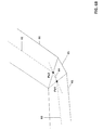
- Fig. 6A shows a vertex Px at an intersection between frames 60 and 61, as well as middle lines 62 and 63 corresponding to the above-mentioned line representation.
- direction changes of the river in particular vertices where the river changes its direction, are identified.
- vertices of the line representation 51 may only be provided at direction changes of the river, such that in those cases the separate identifying of direction changes may be omitted.
- Px is a vertex at a direction change.
- frames 60 and 61 overlap, creating an area 612 which belongs to both frames.
- an area 613 exist which is part of the river, but does not belong to any of frames 60, 61.
- frames 60 and 61 are used for representing the river, this may lead to an unrealistic representation.
- vertex Px in this case vertex Px, is split into two or more vertices, which is shown in Figs. 6B and 6C .
- Px is split into Px1 and Px2, adding an additional line 64 and a triangle 65. In this way, no overlapping zones between frame 60 and 61 and no zone like zone 613 exist.
- FIG. 6C a further example is shown with frames 66, 69 essentially representing the flow of a river which has an outline 68.
- a vertex Px at a direction change is split into two vertices Px1 and Px2 and in this case instead of a triangle a square 611 is inserted (which may also be represented with two triangles).
- Fig. 6C also the construction of vertices Px1, Px2 from vertex Px can be seen. While Px is at an intersection of middle lines 67, 610, Px1 and Px2 are at intersections between lines 610 and 67, respectively, with lines perpendicular to lines 67, 610 starting at an intersection point 614 between frame 66 and frame 69.
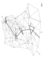
- FIG. 7 an example for a representation of a river 71 in a three-dimensional landscape is shown, wherein the remaining landscape (i.e. the landscape not pertaining to river 71) is represented as a triangulated irregular network 70.
- the remaining landscape i.e. the landscape not pertaining to river 71
- 73A to 73D are triangles which have been inserted by splitting vertices as explained with reference to Figs. 6A and 6B .
- the height of the boundary lines of river 71 i.e. of a polygon representing the river, may be made essentially as already explained with reference to Figs. 3 and 4 , i.e. by an interpolation between the two adjacent vertices.
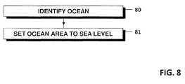
- FIG. 8 a flow chart representing a method according to an embodiment is shown where the predetermined landscape is an ocean.
- the method shown in Fig. 8 may be implemented in the navigation device of Fig. 1 and is an example for an implementation of the actions described with reference to 21 and 22 in Fig. 2 .
- an ocean is identified.
- the area of the ocean for example all vertices defining triangles in a triangulated irregular network which are at least partly covered by the ocean, are set to sea level, i.e. zero meters above sea level. In this way, it is ensured that the ocean is flat and at sea level.
- FIG. 9 shows a flow chart representing an embodiment of a method for handling lakes.
- the method of Fig. 9 may be implemented in the device of Fig. 1 and is an example for the implementation of the actions described with reference to 21 and 22 in Fig. 2 .
- a lake Like an ocean, a lake has an essentially flat surface. However, while an ocean is at or near sea level, a lake may be essentially at any altitude.
- a lake is identified in a landscape to be displayed.
- an average level of altitude of the lake is determined. For example, an average of all vertices contributing to triangles at least partly covered by the lake of a triangulated network may be used, or the average altitude of all vertices covered by the area of the lake may be used.
- a weighted average is determined, wherein for example the weight decreases from a middle of the lake to a shore of the lake. Through such a weighting, the height of influence of the altitude of shore areas is reduced.
- the altitude of the lake is set to the determined average level. For example, the altitude of all vertices defining triangles in the area covered by the lake may be set to the determined level.
- an average level of the lake shore may be determined at 91.
- buildings are stored in a so-called 2,5D-format by storing a circumferential polygon defining the outline of the building, for example in a ground plane thereof, and an general height of the building.
- Fig. 10 a flow chart illustrating a method according to a further embodiment is shown.
- the method of Fig. 10 may be implemented in the navigation device of Fig. 1 and is an example for the actions described with reference to 21 and 22 in Fig. 2 .
- a building is identified in a landscape to be displayed.
- the ground for the building is levelled, i.e. set to a single height. This levelling of the ground can be performed by actually changing vertices defining the ground to obtain a level surface for the building or may be performed "virtually" such that the building is set on a level ground which is different from the grounds that would be defined by vertices for example of a triangulated irregular network.
- Non limitative illustrative examples for the levelling of the ground for a building at 101 will now be explained with reference to Figs. 11A to 11C .
- Fig. 11A a side view of a landscape defined by vertices 111 to 115 together with a building 116 without the application of the method of Fig. 10 are shown.
- the building has a slanted topside, although it, in this simple example, is intended to have equal height on all sides and therefore a levelled top surface.
- the building is positioned directly on vertices 112 and 114. In other situations, the walls of the buildings may be situated between vertices.
- Fig. 11B an actual levelling of the ground is shown.
- vertices 113 is moved to the altitude of vertex 112 to become vertex 113A
- vertex 114 is also moved to the level of vertex 112 to become vertex 114A, such that the building now rests on levelled ground and stands as intended as building 116A. It should be noted that while in the example of Fig.
- the ground is levelled to the altitude of vertex 112, the ground may also be levelled to any other altitudes, for example the altitude of vertex 113 or 114 or also to an altitude being an average of the altitude of the involved vertices or being dependent on the height of the building to be represented, for example the ground may be levelled to an average height of the building or a fraction thereof, for example of the average height.
- Fig. 11C an example for a "virtual" level ground is shown.
- vertices 111 to 115 rest at their place, and a virtual ground 117 on the altitude of vertex 112 is used upon which building 116B rests.
- the height of the building appears smaller at vertex 114 than at vertex 112.
- the altitude of the virtual ground can be set to any desired level, for example -as in Fig. 11C - to the altitude of the lowest vertex involved to an altitude based on an average of the vertices involved or to another desired altitude.
- a more realistic representation of the respective landscape type may be obtained.
- additional vertices or edges may be introduced between the identified landscape type and the surrounding landscape as for example represented by a TIN network.
- a transition function is defined, for example with values from zero to 1, which may be used to fuse adjacent areas, which for example may be represented by adjacent polygons like the above-mentioned river polygon and the triangles defined by the TIN data.
- polygons defining the identified landscape type which has been individually calculated may be left unchanged, and only the surrounding landscape may be adapted.
- some embodiments may employ all the above described embodiments for different landscape types, i.e. may identify rivers, lakes, oceans and buildings and handle them accordingly, whereas other embodiments may only be implemented to handle 1, 2 or 3 of these types. Still other embodiments may be configured to handle other predetermined landscape types than the ones described above in detail. Therefore, it is apparent that the scope of the present invention is not to be construed as being limited to the described embodiments.
Landscapes
- Engineering & Computer Science (AREA)
- Physics & Mathematics (AREA)
- Remote Sensing (AREA)
- Radar, Positioning & Navigation (AREA)
- Geometry (AREA)
- Software Systems (AREA)
- General Physics & Mathematics (AREA)
- Computer Graphics (AREA)
- Theoretical Computer Science (AREA)
- Automation & Control Theory (AREA)
- Processing Or Creating Images (AREA)
- Instructional Devices (AREA)
- Navigation (AREA)
Abstract
Description
- This invention relates to methods and devices for displaying three-dimensional landscapes, for example on displays of navigation devices.
- Navigation devices are nowadays used to guide a user to a destination. Usually, on a display of the navigation device the position of the navigation device is shown with its surroundings. This may be done by showing the position on a map. However, often a three-dimensional perspective is used, i.e. the landscape surrounding the navigation device is displayed in a three-dimensional manner.
- One method for displaying such three-dimensional landscapes are so-called triangulated irregular networks. A triangulated irregular network (TIN) is a digital data structure used for the representation of a three-dimensional surface and is made up of irregular distributed vertices, also referred to as nodes or mass points, and lines with three-dimensional coordinates, for example x, y, z, that are arranged in a network of non-overlapping triangles. TINs may for example be derived from altitude data of a rasterized digital altitude model.
- A TIN therefore comprises a triangular network of vertices with associated coordinates in three dimensions as mentioned above which are connected by edges to form a triangular tessellation. Three-dimensional visualisations can then be created by rendering of the triangular facets. In regions where there is little variation in surface height, i.e. altitude, the vertices may be widely spaced, whereas in areas of more intense variation of the altitude the vertices' density may be increased.
- As explained above, between the vertices the altitude is interpolated, usually in a linear manner (for example, joining vertices by edges as described above constitutes such a linear interpolation). In some cases, this may lead to unnatural looking results. For example, if a river runs between two vertices, the river may be displayed with a slope in a direction perpendicular to its flowing direction, which does not exist for real rivers. Similar problems may occur with other landscape elements.
- Therefore, a need exists for methods and devices capable of displaying three-dimensional landscapes in a more realistic manner.
- This need is met by a method and a device as defined in the independent claims. The dependent claims define further embodiments.
- According to a first aspect of the invention, a method for displaying three-dimensional landscapes is provided, comprising:
- Providing altitude data, e.g. triangulated network data, describing an altitude of a landscape and comprising a plurality of vertices,
- identifying at least one predetermined landscape elements in the landscape to be displayed,
- individually calculating a representation of the at least one predetermined landscape element, and
- displaying the landscape based on the altitude data and the individually calculated representation.
- By identifying elements and individually calculating representations for the identified landscape elements, a misrepresentation of such landscapes elements may be avoided. The predetermined landscape elements may for example comprise rivers, lakes, oceans and/or buildings.
- In case the landscape element is a river, the river may for example be represented by a polygon. In an embodiment, the river may be divided into frames, and the altitude of each frame may be limited to the altitude of the previous frame. In this way, it may be ensured that the river runs downwards.
- Between the frames, bisecting lines may be determined and their intersections with the polygon may be used as vertices for determining the altitudes of the polygon by interpolating between the vertices. In this way, it may be prevented that a river exhibits a slope in a direction not parallel to the flowing direction of the river.
- In another embodiment, a line representation of the river may be provided, for example a line representation running along a middle line of the river. For example, the vector may run in the middle of the aforementioned frames in a flowing direction of the river.
- Direction changes may be identified, and endpoints/starting points of lines at such direction changes may be split, and a triangle or other plateau may be inserted at the direction change.
- In case the predetermined landscape element is an ocean, an altitude of an area covered by the ocean may be set to sea level.
- In case the predetermined landscape element identified is a lake, in an embodiment an average level of the lake is provided. For example, a weighted average may be provided, where a center of the lake may have a higher weight than a boarder of the lake. The altitude of the lake may then be set to the determined average level.
- In a further embodiment, the identified landscape element may be a building, and the ground for the building may be levelled, for example to a lowest altitude according to the altitude data.
- In an embodiment, additional vertices and therefore e.g. additional triangles may be inserted as border areas between the individually calculated representation and the remaining altitude data.
- According to a second aspect of the invention, a device is comprised provided, comprising
a storage storing altitude data comprising a plurality of vertices, and
a processor which is configured to identify predetermined landscape elements in the landscape to be displayed and to individually calculate a representation of the identified at least one predetermined landscape element. Furthermore, the device comprises a display, and the processor is further configured to cause the display to display a landscape based on the altitude data and the individually calculated representation of the at least one predetermined landscape element. The device may be configured to implement any of the methods described above, for example by programming the processor accordingly. - The device may be a navigation device.
- Features of the above described embodiments can be combined with each other, unless specifically noted otherwise.
- Further features and embodiments of the invention will be come apparent from the following detailed description of embodiments with reference to the figures, wherein:
-
Fig. 1 is a block diagram illustrating a device according to an embodiment, -
Fig. 2 is a flow chart representing a method according to an embodiment, -
Fig. 3 is a flow chart representing a method according to a further embodiment, -
Figs. 4A and 4B are explanatory diagrams for illustrating the method ofFig. 3 , -
Fig. 5 is a flow chart of a method according to a further embodiment, -
Figs. 6A to 6C andFig. 7 are explanatory figures illustrating the embodiment ofFig. 5 , -
Fig. 8 is a flow chart of a method according to a further embodiment, -
Fig. 9 is a flow chart of a method according to another embodiment, -
Fig. 10 is a flow chart of a method according to a further embodiment, and -
Figs. 11A to 11C are explanatory diagrams illustrating the method ofFig. 10 . - In the following, embodiments will be described with reference to the figures. It should be noted that these embodiments serve only for illustrating the present invention and are not to be construed as limiting. It should further be noted that features of the embodiments described below may be combined with each other, unless specifically noted otherwise. On the other hand, describing an embodiment with a plurality of features is not to be construed as indicating that all those features are necessary for practicing the present invention, as other embodiments may comprise less features or alternative features.
- In
Fig. 1 , anavigation device 10 according to an embodiment is shown.Navigation device 10 comprises adisplay 11, aprocessor 12, a GPS (Global Positioning System)unit 13 and astorage 14.Processor 12 may be any suitable programmable microprocessor or any other device with processing capabilities, or may also comprise a plurality of sub-processors.Processor 12 executes programs for example stored instorage 14 to provide functionalities ofnavigation device 10. Any conventional functionality of navigation devices may be provided, in particular calculating routes to a desired destination and displaying a current position ondisplay 11, wherein the current position may for example be obtained viaGPS unit 13. - To this end,
storage 14 may comprise anynecessary map data 16 for navigation, similar to conventional navigation devices.Map data 16 may for example give geographical information about the landscape to be displayed, for example the position of elements like streets, buildings, rivers, forests, etc. -
Navigation device 10 in particular is capable of showing the surroundings of the navigation device and therefore of a user of a navigation device, for example the surroundings of a car incorporating the navigation device, or also other scenery, for example a representation of a landscape around a destination of a route, in a three-dimensional manner ondisplay 11. - For this three-dimensional displaying, in
storage 14 triangulated irregular network (TIN)data 15 comprises a plurality of vertices is shown. In other words, the coordinates of a plurality of vertices are stored including their altitude (height) coordinate, and these vertices may then be joint by edges to form triangles which then may be rendered. It should be noted that in other embodiments, instead ofTIN data 15 also other altitude data comprising a plurality of vertices, for example a regular triangulated network where the vertices are equidistantly spaced, may be provided. - It should be noted that the terms "altitude", "height" and "elevation" with respect to vertices are used interchangeably and the context of this application to refer to a height of the vertex above a given reference plane, for example sea level or any other horizontal reference plane.
- In the
navigation device 10 ofFig. 1 , when displaying a three-dimensional landscape ondisplay 11 predetermined landscape types are identified, and the displaying of these predetermined landscape type deviates from the displaying of the remaining landscape, which is conventionally then based onTIN data 15. - It should be noted that
Fig. 1 shows only some possible components of a navigation device, and other components like a user interface or an audio output are also possible. On the other hand, the application of the present invention is not restricted to navigation devices, but may also be employed in other cases, where three-dimensional landscapes are to be displayed on a display. Various implementations of the above-mentioned identifying and displaying of predetermined landscape types will be explained in the following with reference toFigs. 2 to 11 . - In
Fig. 2 , a flow chart representing a method according to an embodiment is shown. The methods ofFig. 2 may be implemented in the device ofFig. 1 , for example by programmingprocessor 12 accordingly, but may also be implemented independently therefrom. - At 20, TIN data is provided, for example by providing TIN data in a storage like
storage 14. Furthermore, at 20 map data likemap data 16 ofFig. 1 is provided. - At 21, predetermined landscape types in a landscape to be displayed are identified, for example based on the map data. Predetermined landscape types may be types which, when displayed on TIN data alone, lead potentially to unrealistic results. Such landscape types may for example comprise rivers, lakes, oceans or buildings.
- At 22, 3D representations of the identified landscape types are calculated which may deviate from a representation based on the triangulated irregular network and may lead to a more realistic representation. The actions described with reference to 21 and 22 may for example be performed by
processor 12 ofFig. 1 . - At 23, the landscape is displayed based on the TIN data and based on the calculated representation of the identified landscape types. In other words, in an embodiment for the identified landscape types the calculated representation is used, whereas for the remaining landscape the TIN data is used for displaying.
- Examples for the calculation of representations of identified landscape types according to some embodiments will next be explained.
- First, with reference to
Figs. 3 and4 a method for handling a river in some embodiments of the present invention will be described. The method may for example be implemented in the navigation device ofFig. 1 and is an example for the implementation of the actions described with reference to 21 and 22 inFig. 2 in case the predetermined landscape type is a river. However, it is to be noted that the embodiment ofFig. 3 may also be implemented independently from the embodiments ofFigs. 1 and2 . - In
Fig. 3 a flow chart representing a method according to an embodiment is shown. InFigs. 4A and 4B , illustrative, non-limiting diagrams illustrating the method ofFig. 3 further are shown. - At 30 in
Fig. 3 , a river is identified in a landscape to be displayed. The river, for example in a map database, may for example be represented by a polygon approximating the outline of the river. For example, inFigs. 4A and 4B apolygon 43 is shown representing a river. - At 31, the river is then divided into oriented frames, which in particular may be rectangles oriented according to a (main) direction of the river in the area covered by the frames. For example, in
Figs. 4A frames 40A, 40B and 40C are shown. A criterion whether a given frame is to be further subdivided into two or more frames may be based on a maximum altitude difference of the vertices of the triangular irregular network or other altitude data in the area covered by the frames. For example, if the maximum altitude difference is below a predetermined threshold value, no further subdivision is made. - With each frame, a minimum altitude (height) of the vertices in the area covered by the respective frame may be associated. By using this minimum altitude as associated altitude for the frame, in some embodiments it may be achieved that the river is represented nowhere higher than the river bank.
- At 32, the altitude of each frame is limited to the height of the previous frame in an orographic direction, i.e. the direction the river flows. In this way, it is ensured in the presently discussed embodiment that the river in the final 3D representation always runs downward. For example, if a frame has an associated altitude greater than the altitude of the previous frame, the altitude of this frame is set to the altitude of the previous frame.
- At 33, bisecting lines between adjacent frames are determined. For example, in
Figs. 4 abisecting line 42A betweenframes bisecting line 42B betweenframes auxiliary lines 41A to 41D are depicted inFig. 4A which run along frame borders as shown.Bisecting line 42A bisects and angle formed byauxiliary lines line 42B bisects an angle formed byauxiliary lines - At 34 in
Fig. 3 , intersections of the bisecting lines determined at 33 with the polygon describing the river are determined. In the example ofFig. 4 , inFig. 4B intersection points 44A and 44B where bisectingline 42A intersects thepolygon 43 andintersection points line 42B intersectspolygon 43 are shown as examples. At 35, the altitudes for the river polygon are set. To this end, intersection points determined at 34 associated with the same bisecting line, for example intersection points 44A and 44B orintersection points Fig. 4B , are set to the same altitude, which may be the average altitude associated with the two frames adjacent to the respective bisecting lines, forexample frames line 42 A and frames 40B and 40C for bisectingline 42B. The altitudes of the remaining points of the river polygon may be linearly interpolated between the intersection points. In another embodiment, the river point polygon may for example be replaced by triangles, for example inFig. 4B the section between intersectingline 42A and bisectingline 42B may be represented by a first triangle with thevertices vertices - A further method for handling a river which may be implemented in the device of
Fig. 1 and which is an example for an implementation of the actions described with reference to 21 and 22 inFig. 2 will next be explained with reference toFigs. 5 to 7 .Fig. 5 shows a flow chart representing an embodiment of a method according to the present invention, andFigs. 6 and7 show illustrative diagrams for explaining some features of the embodiment ofFig. 5 . - The method of
Fig. 5 may be implemented as an alternative to the method ofFig. 3 . However, it should be noted that features from the embodiment ofFigs. 3 and5 may also be mixed to form further embodiments. Furthermore, a single device likenavigation device 10 ofFig. 1 may implement both methods. - At 50, a river is identified in a landscape to be displayed, for example based on map data. At 51, a line representation, for example a vector representation, of the river is provided. The line representation may for example represent a middle line of the river. A general example for a line representation is shown in
Fig. 7 bearing reference numeral 74. In particular, the line representation may consist of a plurality of vertices arranged in the middle line of a river, i.e. a connection of the vertices corresponding to the middle line of the river, the vertices representing direction changes. The connections between the vertices may also be seen as vectors, a direction of the vector indicating the flowing direction of the river. - The vertices of the line representation may for example be obtained based on a polygon representing the river like
polygon 43 ofFig. 4 and may correspond to a middle line of the polygon. In an embodiment, the vertices of the line representation may correspond to middle point between the intersection points of the bisecting lines, for example a middle point betweenpoints Fig. 4B and a middle point betweenpoints Fig. 4 . In this case, the altitude of the vertices may be determined as has been described for the determination of the altitude of the intersection points with reference toFig.2 , i.e. based on oriented frames with which a height is associated. - For example,
Fig. 6A shows a vertex Px at an intersection betweenframes middle lines - At 52, direction changes of the river, in particular vertices where the river changes its direction, are identified. In some embodiments, vertices of the
line representation 51 may only be provided at direction changes of the river, such that in those cases the separate identifying of direction changes may be omitted. - At 53 in
Fig. 5 , the vertices are split at direction changes. This will be explained using an illustrative example with reference toFigs. 6A to 6C . - In the already explained
Fig. 6A , Px is a vertex at a direction change. As can be seen inFig. 6A , frames 60 and 61 overlap, creating anarea 612 which belongs to both frames. On the other hand, anarea 613 exist which is part of the river, but does not belong to any offrames - Therefore, in the currently discussed embodiment at such a direction change the vertex, in this case vertex Px, is split into two or more vertices, which is shown in
Figs. 6B and6C . InFig. 6B Px is split into Px1 and Px2, adding anadditional line 64 and atriangle 65. In this way, no overlapping zones betweenframe zone 613 exist. - In
Fig. 6C , a further example is shown withframes outline 68. A vertex Px at a direction change is split into two vertices Px1 and Px2 and in this case instead of a triangle a square 611 is inserted (which may also be represented with two triangles). InFig. 6C , also the construction of vertices Px1, Px2 from vertex Px can be seen. While Px is at an intersection ofmiddle lines lines lines intersection point 614 betweenframe 66 andframe 69. - In
Fig. 7 , an example for a representation of ariver 71 in a three-dimensional landscape is shown, wherein the remaining landscape (i.e. the landscape not pertaining to river 71) is represented as a triangulatedirregular network 70. With 74 as already mentioned a line representation ofriver 71 is designated, and 73A to 73D are triangles which have been inserted by splitting vertices as explained with reference toFigs. 6A and6B . - As already explained, instead of triangles in some case also squares, which may be seen as a combination of triangles may be used. Moreover, the height of the boundary lines of
river 71, i.e. of a polygon representing the river, may be made essentially as already explained with reference toFigs. 3 and4 , i.e. by an interpolation between the two adjacent vertices. - As already mentioned, besides rivers other predetermined landscape types may be identified in embodiments of the present invention. In
Fig. 8 , a flow chart representing a method according to an embodiment is shown where the predetermined landscape is an ocean. The method shown inFig. 8 may be implemented in the navigation device ofFig. 1 and is an example for an implementation of the actions described with reference to 21 and 22 inFig. 2 . - At 80 in
Fig. 8 , an ocean is identified. At 81, the area of the ocean, for example all vertices defining triangles in a triangulated irregular network which are at least partly covered by the ocean, are set to sea level, i.e. zero meters above sea level. In this way, it is ensured that the ocean is flat and at sea level. - Another possible predetermined landscape is a lake, which is somewhat similar to an ocean.
Fig. 9 shows a flow chart representing an embodiment of a method for handling lakes. The method ofFig. 9 may be implemented in the device ofFig. 1 and is an example for the implementation of the actions described with reference to 21 and 22 inFig. 2 . - Like an ocean, a lake has an essentially flat surface. However, while an ocean is at or near sea level, a lake may be essentially at any altitude.
- At 90, a lake is identified in a landscape to be displayed. At 91, an average level of altitude of the lake is determined. For example, an average of all vertices contributing to triangles at least partly covered by the lake of a triangulated network may be used, or the average altitude of all vertices covered by the area of the lake may be used. In an embodiment, a weighted average is determined, wherein for example the weight decreases from a middle of the lake to a shore of the lake. Through such a weighting, the height of influence of the altitude of shore areas is reduced.
- At 92, the altitude of the lake is set to the determined average level. For example, the altitude of all vertices defining triangles in the area covered by the lake may be set to the determined level.
- In other embodiments, for example an average level of the lake shore may be determined at 91.
- A further type of landscape, which may for example be identified at 21 of
Fig. 2 are buildings. In some embodiments, buildings are stored in a so-called 2,5D-format by storing a circumferential polygon defining the outline of the building, for example in a ground plane thereof, and an general height of the building. - In
Fig. 10 , a flow chart illustrating a method according to a further embodiment is shown. The method ofFig. 10 may be implemented in the navigation device ofFig. 1 and is an example for the actions described with reference to 21 and 22 inFig. 2 . - At 100, a building is identified in a landscape to be displayed. At 101, the ground for the building is levelled, i.e. set to a single height. This levelling of the ground can be performed by actually changing vertices defining the ground to obtain a level surface for the building or may be performed "virtually" such that the building is set on a level ground which is different from the grounds that would be defined by vertices for example of a triangulated irregular network.
- Non limitative illustrative examples for the levelling of the ground for a building at 101 will now be explained with reference to
Figs. 11A to 11C . - In
Fig. 11A , a side view of a landscape defined byvertices 111 to 115 together with abuilding 116 without the application of the method ofFig. 10 are shown. As inparticular vertices vertices - In
Fig. 11B , an actual levelling of the ground is shown. In the example ofFigs. 11B ,vertices 113 is moved to the altitude ofvertex 112 to become vertex 113A, andvertex 114 is also moved to the level ofvertex 112 to becomevertex 114A, such that the building now rests on levelled ground and stands as intended as building 116A. It should be noted that while in the example ofFig. 11B the ground is levelled to the altitude ofvertex 112, the ground may also be levelled to any other altitudes, for example the altitude ofvertex - In
Fig. 11C , an example for a "virtual" level ground is shown. In the example ofFig. 11C ,vertices 111 to 115 rest at their place, and avirtual ground 117 on the altitude ofvertex 112 is used upon whichbuilding 116B rests. In this case, the height of the building appears smaller atvertex 114 than atvertex 112. Also in the case of a virtual ground, the altitude of the virtual ground can be set to any desired level, for example -as inFig. 11C - to the altitude of the lowest vertex involved to an altitude based on an average of the vertices involved or to another desired altitude. - In the embodiments described above, through the individual calculation of a representation of the identified predetermined landscape a more realistic representation of the respective landscape type may be obtained. It should be noted that in some embodiments additional vertices or edges may be introduced between the identified landscape type and the surrounding landscape as for example represented by a TIN network. In some examples, a transition function is defined, for example with values from zero to 1, which may be used to fuse adjacent areas, which for example may be represented by adjacent polygons like the above-mentioned river polygon and the triangles defined by the TIN data. For such a fusing or blending of adjacent polygons, polygons defining the identified landscape type which has been individually calculated may be left unchanged, and only the surrounding landscape may be adapted.
- It should be noted that the various actions and operations described for the above-mentioned methods need not necessarily be performed in the indicated order. For example, in the embodiment of
Fig. 3 , first the bisecting lines and the intersecting lines may be determined (33 and 34), and then the elevation of a frame may be limited to the elevation of a previous frame (32). - Furthermore, some embodiments may employ all the above described embodiments for different landscape types, i.e. may identify rivers, lakes, oceans and buildings and handle them accordingly, whereas other embodiments may only be implemented to handle 1, 2 or 3 of these types. Still other embodiments may be configured to handle other predetermined landscape types than the ones described above in detail. Therefore, it is apparent that the scope of the present invention is not to be construed as being limited to the described embodiments.
Claims (15)
- A method for displaying a three-dimensional landscape, comprising:- providing altitude data (15) describing an altitude of a landscape and comprising a plurality of vertices,- identifying at least one predetermined landscape element (71; 116) in the landscape,- individually calculating a representation of the at least one predetermined landscape element (71; 116), and- displaying the landscape based on the plurality of vertices and the individually calculated representation of the at least one landscape element (71; 116).
- The method of claim 1, wherein the altitude data (15) comprises triangulated irregular network data.
- The method of claim 1 or claim 2, wherein the at least one predetermined landscape element comprises at least one element from the group consisting of a river (71), a lake, an ocean and a building (116).
- The method of any one of claims 1-3, wherein the at least one predetermined landscape element comprises a river, and wherein the individually calculating a representation of the river comprises:- dividing the river into oriented frames (40A, 40B, 40C), and- limiting an altitude of each frame (40A, 40B, 40C) to an altitude to a previous frame.
- The method of claim 4, wherein individually calculating the representation of the river further comprises assigning each frame of the oriented frames (40A, 40B, 40C) an altitude based on the altitudes of vertices in an area covered by the frame.
- The method of claim 4 or 5, wherein individually calculating the representation of the river further comprises:- determining bisecting lines (42A, 42B) between adjacent ones of the oriented frames (40A, 40B, 40C),- determining intersections (44A-44D) of the bisecting lines (42A, 42B) with a polygon (43) representing the river, and- setting altitudes of the polygon (43) based on altitudes of the intersections (44A-44D).
- The method of any one of claims 1-6, wherein the at least one predetermined landscape element comprises a river (71), wherein individually calculating a representation of the river comprises:- providing a line representation of the river (71), the line representation comprising line running between a series of river vertices (Px),- identifying direction changes of the line representation, and- splitting at least one river vertex (Px) at a direction change into at least two further river vertices (Px1, Px2).
- The method of claim 7, further comprising inserting a plateau, wherein a border of the plateau runs through the further river vertices (Px1, Px2).
- The method of claim 8, wherein the plateau is selected from the group consisting of a triangle (65, 73A-73D) and a square (611).
- The method of any one of claims 1-9,
wherein the at least one predetermined landscape element comprises an ocean,
wherein individually calculating a representation of the ocean comprises setting an altitude of an area covered by the ocean to sea level. - The method of any one of claims 1-10,
wherein the at least one predetermined landscape element comprises a lake,
wherein individually calculating a representation of the lake comprises determining a lake level based on altitudes of vertices in the area covered by the lake, and
setting the altitude of the lake to the lake level. - The method of claim 11, wherein determining the lake level comprises calculating a weighted average of the altitudes of the vertices in the lake area.
- The method of any one of claims 1-12, wherein the at least one predetermined landscape element comprises a building (116),
wherein individually calculating a representation of the building comprises levelling a ground for the building. - The method of claim 13, wherein levelling the ground comprises one of setting vertices (112-114) in the area covered by the building to a common ground level and providing a virtual ground level (117).
- A device, comprising:- a processor (12),- a storage (14) configured to store altitude data of a landscape and map data (16) of a landscape, and- a display (11),
wherein the processor (12) is configured to identify at least one predetermined landscape element (71; 116) in a landscape to be displayed, to individually calculate a representation of the at least one predetermined landscape element, and cause the display (11) to display the landscape based on the individually calculated representation of the at least one predetermined landscape element (71; 116) and the altitude data.
Priority Applications (2)
| Application Number | Priority Date | Filing Date | Title |
|---|---|---|---|
| EP11165443.0A EP2523167B1 (en) | 2011-05-10 | 2011-05-10 | Methods and devices for displaying three-dimensional landscapes |
| US13/468,375 US9501867B2 (en) | 2011-05-10 | 2012-05-10 | System for displaying three-dimensional landscapes |
Applications Claiming Priority (1)
| Application Number | Priority Date | Filing Date | Title |
|---|---|---|---|
| EP11165443.0A EP2523167B1 (en) | 2011-05-10 | 2011-05-10 | Methods and devices for displaying three-dimensional landscapes |
Publications (2)
| Publication Number | Publication Date |
|---|---|
| EP2523167A1 true EP2523167A1 (en) | 2012-11-14 |
| EP2523167B1 EP2523167B1 (en) | 2016-03-23 |
Family
ID=44117723
Family Applications (1)
| Application Number | Title | Priority Date | Filing Date |
|---|---|---|---|
| EP11165443.0A Active EP2523167B1 (en) | 2011-05-10 | 2011-05-10 | Methods and devices for displaying three-dimensional landscapes |
Country Status (2)
| Country | Link |
|---|---|
| US (1) | US9501867B2 (en) |
| EP (1) | EP2523167B1 (en) |
Citations (1)
| Publication number | Priority date | Publication date | Assignee | Title |
|---|---|---|---|---|
| US20090074254A1 (en) * | 2007-07-13 | 2009-03-19 | Todd Jamison | System and methods for dynamically generating earth position data for overhead images and derived information |
Family Cites Families (2)
| Publication number | Priority date | Publication date | Assignee | Title |
|---|---|---|---|---|
| US20050107946A1 (en) * | 2003-11-13 | 2005-05-19 | Takanori Shimizu | Vehicle navigation apparatus |
| EP2569659A4 (en) * | 2010-05-10 | 2017-11-08 | Groundswell Technologies, Inc. | Method and apparatus for groundwater basin storage tracking, remediation performance monitoring and optimization |
-
2011
- 2011-05-10 EP EP11165443.0A patent/EP2523167B1/en active Active
-
2012
- 2012-05-10 US US13/468,375 patent/US9501867B2/en active Active
Patent Citations (1)
| Publication number | Priority date | Publication date | Assignee | Title |
|---|---|---|---|---|
| US20090074254A1 (en) * | 2007-07-13 | 2009-03-19 | Todd Jamison | System and methods for dynamically generating earth position data for overhead images and derived information |
Non-Patent Citations (6)
| Title |
|---|
| DOUGLAS D H: "Experiments with a ridge and channel digital elevation model", PROCEEDINGS / GRAPHICS INTERFACE '84, 28 MAY - 1 JUNE, 1984, OTTAWA, ONTARIO = COMPTES RENDUS INTERFACE GRAPHIQUE '84 / [SPONSORED BY THE CANADIAN MAN-], COMPUTER COMMUNICATIONS SOCIETY AND THE NATIONAL COMPUTER GRAPHICS ASSOCIATION OF CANADA, CA, 28 May 1984 (1984-05-28), pages 235 - 237, XP008144673 * |
| ENRIQUE R VIVONI ET AL: "Generation of Triangulated Irregular Networks Based on Hydrological Similarity", JOURNAL OF HYDROLOGIC ENGINEERING, vol. 9, no. 4, 1 January 2004 (2004-01-01), THE SOCIETY, NEW YORK, NY, US, pages 288 - 302, XP008149547, ISSN: 1084-0699, DOI: 10.1061/(ASCE)1084-0699(2004)9:4(288) * |
| F PENNINGA: "Towards 3D Topography using a Feature-based Integrated TIN/TEN Model", 2005, XP002662476, Retrieved from the Internet <URL:ftp://ftp.ecn.purdue.edu/jshan/proceedings/topology_ucl2005/Integrated_TIN_TEN.pdf> [retrieved on 20111031] * |
| JAMES NELSON E ET AL: "Adaptive Tessellation Method for Creating TINS from GIS Data", JOURNAL OF HYDROLOGIC ENGINEERING, vol. 4, no. 1, 1 January 1999 (1999-01-01), THE SOCIETY, NEW YORK, NY, US, pages 1 - 8, XP008149540, ISSN: 1084-0699, DOI: 10.1061/(ASCE)1084-0699(1999)4:1(2) * |
| NELSON JAMES ET AL: "Algorithm for precise drainage-basin delineation", JOURNAL OF HYDRAULIC ENGINEERING, vol. 120, no. 3, 1 March 1994 (1994-03-01), AMERICAN SOCIETY OF CIVIL ENGINEERS, NEW YORK, NY, US, pages 298 - 312, XP008149541, ISSN: 0733-9429 * |
| R. I. SILVEIRA: ""Optimization of polyhedral terrains"", 1 January 2009 (2009-01-01), UTRECHT UNIVERSITY, pages 157PP, XP002671155, Retrieved from the Internet <URL:http://www-ma2.upc.edu/rsilveira/pubs/PhDThesis.pdf> [retrieved on 20120309] * |
Also Published As
| Publication number | Publication date |
|---|---|
| US20150042639A1 (en) | 2015-02-12 |
| EP2523167B1 (en) | 2016-03-23 |
| US9501867B2 (en) | 2016-11-22 |
Similar Documents
| Publication | Publication Date | Title |
|---|---|---|
| CN112710325A (en) | Navigation guidance and live-action three-dimensional model establishing method, device, equipment and medium | |
| EP2725323B1 (en) | Map viewer and method | |
| EP2546821A1 (en) | Three-dimensional map drawing system | |
| US8532924B2 (en) | Method and apparatus for displaying three-dimensional terrain and route guidance | |
| CN102538754B (en) | Method and equipment for calculating road gradient information | |
| JP5997640B2 (en) | 3D image output apparatus and background image generation apparatus | |
| JP5883818B2 (en) | 3D map display system | |
| US20130169685A1 (en) | Path side image on map overlay | |
| JP6205183B2 (en) | Map data generation system, map output system | |
| US9549169B2 (en) | Stereoscopic map display system | |
| JP5964771B2 (en) | 3D map display device, 3D map display method, and computer program | |
| WO2014199873A1 (en) | Map-data generation system and map output system | |
| CN105474269A (en) | Three-dimensional-map display system | |
| JP6022386B2 (en) | 3D map display device, 3D map display method, and computer program | |
| US20160239996A1 (en) | 3d map display system | |
| Koch et al. | Semantically correct 2.5 D GIS data—The integration of a DTM and topographic vector data | |
| US9501867B2 (en) | System for displaying three-dimensional landscapes | |
| CN108376423A (en) | A kind of safety in production VR real training guidance path dynamic programming methods and system | |
| JP4543820B2 (en) | Three-dimensional data processing apparatus and program | |
| CN101163943B (en) | Method for displaying digital road map in three dimensions | |
| KR100981661B1 (en) | Apparatus and method for displaying 3d path | |
| KR100545359B1 (en) | 3D terrain representation device and its method using digital drawing data | |
| JP6161348B2 (en) | Stereoscopic image data generation device | |
| JP5232380B2 (en) | Map display device | |
| JP2007041692A (en) | 3D terrain data control device and 3D terrain data control method |
Legal Events
| Date | Code | Title | Description |
|---|---|---|---|
| PUAI | Public reference made under article 153(3) epc to a published international application that has entered the european phase |
Free format text: ORIGINAL CODE: 0009012 |
|
| AK | Designated contracting states |
Kind code of ref document: A1 Designated state(s): AL AT BE BG CH CY CZ DE DK EE ES FI FR GB GR HR HU IE IS IT LI LT LU LV MC MK MT NL NO PL PT RO RS SE SI SK SM TR |
|
| AX | Request for extension of the european patent |
Extension state: BA ME |
|
| 17P | Request for examination filed |
Effective date: 20130513 |
|
| REG | Reference to a national code |
Ref country code: DE Ref legal event code: R079 Ref document number: 602011024234 Country of ref document: DE Free format text: PREVIOUS MAIN CLASS: G06T0017050000 Ipc: G06T0017200000 |
|
| RIC1 | Information provided on ipc code assigned before grant |
Ipc: G06T 17/05 20110101ALI20150730BHEP Ipc: G06T 17/20 20060101AFI20150730BHEP |
|
| GRAP | Despatch of communication of intention to grant a patent |
Free format text: ORIGINAL CODE: EPIDOSNIGR1 |
|
| INTG | Intention to grant announced |
Effective date: 20150908 |
|
| GRAS | Grant fee paid |
Free format text: ORIGINAL CODE: EPIDOSNIGR3 |
|
| GRAA | (expected) grant |
Free format text: ORIGINAL CODE: 0009210 |
|
| AK | Designated contracting states |
Kind code of ref document: B1 Designated state(s): AL AT BE BG CH CY CZ DE DK EE ES FI FR GB GR HR HU IE IS IT LI LT LU LV MC MK MT NL NO PL PT RO RS SE SI SK SM TR |
|
| REG | Reference to a national code |
Ref country code: GB Ref legal event code: FG4D |
|
| REG | Reference to a national code |
Ref country code: CH Ref legal event code: EP |
|
| REG | Reference to a national code |
Ref country code: AT Ref legal event code: REF Ref document number: 783798 Country of ref document: AT Kind code of ref document: T Effective date: 20160415 |
|
| REG | Reference to a national code |
Ref country code: IE Ref legal event code: FG4D |
|
| REG | Reference to a national code |
Ref country code: DE Ref legal event code: R096 Ref document number: 602011024234 Country of ref document: DE |
|
| REG | Reference to a national code |
Ref country code: LT Ref legal event code: MG4D |
|
| REG | Reference to a national code |
Ref country code: NL Ref legal event code: MP Effective date: 20160323 |
|
| PG25 | Lapsed in a contracting state [announced via postgrant information from national office to epo] |
Ref country code: NO Free format text: LAPSE BECAUSE OF FAILURE TO SUBMIT A TRANSLATION OF THE DESCRIPTION OR TO PAY THE FEE WITHIN THE PRESCRIBED TIME-LIMIT Effective date: 20160623 Ref country code: HR Free format text: LAPSE BECAUSE OF FAILURE TO SUBMIT A TRANSLATION OF THE DESCRIPTION OR TO PAY THE FEE WITHIN THE PRESCRIBED TIME-LIMIT Effective date: 20160323 Ref country code: GR Free format text: LAPSE BECAUSE OF FAILURE TO SUBMIT A TRANSLATION OF THE DESCRIPTION OR TO PAY THE FEE WITHIN THE PRESCRIBED TIME-LIMIT Effective date: 20160624 Ref country code: FI Free format text: LAPSE BECAUSE OF FAILURE TO SUBMIT A TRANSLATION OF THE DESCRIPTION OR TO PAY THE FEE WITHIN THE PRESCRIBED TIME-LIMIT Effective date: 20160323 |
|
| REG | Reference to a national code |
Ref country code: AT Ref legal event code: MK05 Ref document number: 783798 Country of ref document: AT Kind code of ref document: T Effective date: 20160323 |
|
| PG25 | Lapsed in a contracting state [announced via postgrant information from national office to epo] |
Ref country code: SE Free format text: LAPSE BECAUSE OF FAILURE TO SUBMIT A TRANSLATION OF THE DESCRIPTION OR TO PAY THE FEE WITHIN THE PRESCRIBED TIME-LIMIT Effective date: 20160323 Ref country code: BE Free format text: LAPSE BECAUSE OF NON-PAYMENT OF DUE FEES Effective date: 20160531 Ref country code: NL Free format text: LAPSE BECAUSE OF FAILURE TO SUBMIT A TRANSLATION OF THE DESCRIPTION OR TO PAY THE FEE WITHIN THE PRESCRIBED TIME-LIMIT Effective date: 20160323 Ref country code: RS Free format text: LAPSE BECAUSE OF FAILURE TO SUBMIT A TRANSLATION OF THE DESCRIPTION OR TO PAY THE FEE WITHIN THE PRESCRIBED TIME-LIMIT Effective date: 20160323 Ref country code: LV Free format text: LAPSE BECAUSE OF FAILURE TO SUBMIT A TRANSLATION OF THE DESCRIPTION OR TO PAY THE FEE WITHIN THE PRESCRIBED TIME-LIMIT Effective date: 20160323 Ref country code: LT Free format text: LAPSE BECAUSE OF FAILURE TO SUBMIT A TRANSLATION OF THE DESCRIPTION OR TO PAY THE FEE WITHIN THE PRESCRIBED TIME-LIMIT Effective date: 20160323 |
|
| PG25 | Lapsed in a contracting state [announced via postgrant information from national office to epo] |
Ref country code: IS Free format text: LAPSE BECAUSE OF FAILURE TO SUBMIT A TRANSLATION OF THE DESCRIPTION OR TO PAY THE FEE WITHIN THE PRESCRIBED TIME-LIMIT Effective date: 20160723 Ref country code: PL Free format text: LAPSE BECAUSE OF FAILURE TO SUBMIT A TRANSLATION OF THE DESCRIPTION OR TO PAY THE FEE WITHIN THE PRESCRIBED TIME-LIMIT Effective date: 20160323 Ref country code: EE Free format text: LAPSE BECAUSE OF FAILURE TO SUBMIT A TRANSLATION OF THE DESCRIPTION OR TO PAY THE FEE WITHIN THE PRESCRIBED TIME-LIMIT Effective date: 20160323 |
|
| PG25 | Lapsed in a contracting state [announced via postgrant information from national office to epo] |
Ref country code: PT Free format text: LAPSE BECAUSE OF FAILURE TO SUBMIT A TRANSLATION OF THE DESCRIPTION OR TO PAY THE FEE WITHIN THE PRESCRIBED TIME-LIMIT Effective date: 20160725 Ref country code: SM Free format text: LAPSE BECAUSE OF FAILURE TO SUBMIT A TRANSLATION OF THE DESCRIPTION OR TO PAY THE FEE WITHIN THE PRESCRIBED TIME-LIMIT Effective date: 20160323 Ref country code: ES Free format text: LAPSE BECAUSE OF FAILURE TO SUBMIT A TRANSLATION OF THE DESCRIPTION OR TO PAY THE FEE WITHIN THE PRESCRIBED TIME-LIMIT Effective date: 20160323 Ref country code: RO Free format text: LAPSE BECAUSE OF FAILURE TO SUBMIT A TRANSLATION OF THE DESCRIPTION OR TO PAY THE FEE WITHIN THE PRESCRIBED TIME-LIMIT Effective date: 20160323 Ref country code: CZ Free format text: LAPSE BECAUSE OF FAILURE TO SUBMIT A TRANSLATION OF THE DESCRIPTION OR TO PAY THE FEE WITHIN THE PRESCRIBED TIME-LIMIT Effective date: 20160323 Ref country code: SK Free format text: LAPSE BECAUSE OF FAILURE TO SUBMIT A TRANSLATION OF THE DESCRIPTION OR TO PAY THE FEE WITHIN THE PRESCRIBED TIME-LIMIT Effective date: 20160323 Ref country code: AT Free format text: LAPSE BECAUSE OF FAILURE TO SUBMIT A TRANSLATION OF THE DESCRIPTION OR TO PAY THE FEE WITHIN THE PRESCRIBED TIME-LIMIT Effective date: 20160323 |
|
| PG25 | Lapsed in a contracting state [announced via postgrant information from national office to epo] |
Ref country code: IT Free format text: LAPSE BECAUSE OF FAILURE TO SUBMIT A TRANSLATION OF THE DESCRIPTION OR TO PAY THE FEE WITHIN THE PRESCRIBED TIME-LIMIT Effective date: 20160323 Ref country code: LU Free format text: LAPSE BECAUSE OF FAILURE TO SUBMIT A TRANSLATION OF THE DESCRIPTION OR TO PAY THE FEE WITHIN THE PRESCRIBED TIME-LIMIT Effective date: 20160510 Ref country code: BE Free format text: LAPSE BECAUSE OF FAILURE TO SUBMIT A TRANSLATION OF THE DESCRIPTION OR TO PAY THE FEE WITHIN THE PRESCRIBED TIME-LIMIT Effective date: 20160323 |
|
| REG | Reference to a national code |
Ref country code: CH Ref legal event code: PL |
|
| REG | Reference to a national code |
Ref country code: DE Ref legal event code: R097 Ref document number: 602011024234 Country of ref document: DE |
|
| PLBE | No opposition filed within time limit |
Free format text: ORIGINAL CODE: 0009261 |
|
| STAA | Information on the status of an ep patent application or granted ep patent |
Free format text: STATUS: NO OPPOSITION FILED WITHIN TIME LIMIT |
|
| PG25 | Lapsed in a contracting state [announced via postgrant information from national office to epo] |
Ref country code: CH Free format text: LAPSE BECAUSE OF NON-PAYMENT OF DUE FEES Effective date: 20160531 Ref country code: LI Free format text: LAPSE BECAUSE OF NON-PAYMENT OF DUE FEES Effective date: 20160531 Ref country code: DK Free format text: LAPSE BECAUSE OF FAILURE TO SUBMIT A TRANSLATION OF THE DESCRIPTION OR TO PAY THE FEE WITHIN THE PRESCRIBED TIME-LIMIT Effective date: 20160323 |
|
| REG | Reference to a national code |
Ref country code: IE Ref legal event code: MM4A |
|
| PG25 | Lapsed in a contracting state [announced via postgrant information from national office to epo] |
Ref country code: BG Free format text: LAPSE BECAUSE OF FAILURE TO SUBMIT A TRANSLATION OF THE DESCRIPTION OR TO PAY THE FEE WITHIN THE PRESCRIBED TIME-LIMIT Effective date: 20160623 |
|
| 26N | No opposition filed |
Effective date: 20170102 |
|
| GBPC | Gb: european patent ceased through non-payment of renewal fee |
Effective date: 20160623 |
|
| REG | Reference to a national code |
Ref country code: FR Ref legal event code: ST Effective date: 20170131 |
|
| PG25 | Lapsed in a contracting state [announced via postgrant information from national office to epo] |
Ref country code: FR Free format text: LAPSE BECAUSE OF NON-PAYMENT OF DUE FEES Effective date: 20160531 |
|
| PG25 | Lapsed in a contracting state [announced via postgrant information from national office to epo] |
Ref country code: SI Free format text: LAPSE BECAUSE OF FAILURE TO SUBMIT A TRANSLATION OF THE DESCRIPTION OR TO PAY THE FEE WITHIN THE PRESCRIBED TIME-LIMIT Effective date: 20160323 Ref country code: IE Free format text: LAPSE BECAUSE OF NON-PAYMENT OF DUE FEES Effective date: 20160510 Ref country code: GB Free format text: LAPSE BECAUSE OF NON-PAYMENT OF DUE FEES Effective date: 20160623 |
|
| PG25 | Lapsed in a contracting state [announced via postgrant information from national office to epo] |
Ref country code: HU Free format text: LAPSE BECAUSE OF FAILURE TO SUBMIT A TRANSLATION OF THE DESCRIPTION OR TO PAY THE FEE WITHIN THE PRESCRIBED TIME-LIMIT; INVALID AB INITIO Effective date: 20110510 Ref country code: CY Free format text: LAPSE BECAUSE OF FAILURE TO SUBMIT A TRANSLATION OF THE DESCRIPTION OR TO PAY THE FEE WITHIN THE PRESCRIBED TIME-LIMIT Effective date: 20160323 |
|
| PG25 | Lapsed in a contracting state [announced via postgrant information from national office to epo] |
Ref country code: MC Free format text: LAPSE BECAUSE OF FAILURE TO SUBMIT A TRANSLATION OF THE DESCRIPTION OR TO PAY THE FEE WITHIN THE PRESCRIBED TIME-LIMIT Effective date: 20160323 Ref country code: MT Free format text: LAPSE BECAUSE OF NON-PAYMENT OF DUE FEES Effective date: 20160531 Ref country code: TR Free format text: LAPSE BECAUSE OF FAILURE TO SUBMIT A TRANSLATION OF THE DESCRIPTION OR TO PAY THE FEE WITHIN THE PRESCRIBED TIME-LIMIT Effective date: 20160323 Ref country code: MK Free format text: LAPSE BECAUSE OF FAILURE TO SUBMIT A TRANSLATION OF THE DESCRIPTION OR TO PAY THE FEE WITHIN THE PRESCRIBED TIME-LIMIT Effective date: 20160323 |
|
| PG25 | Lapsed in a contracting state [announced via postgrant information from national office to epo] |
Ref country code: AL Free format text: LAPSE BECAUSE OF FAILURE TO SUBMIT A TRANSLATION OF THE DESCRIPTION OR TO PAY THE FEE WITHIN THE PRESCRIBED TIME-LIMIT Effective date: 20160323 |
|
| P01 | Opt-out of the competence of the unified patent court (upc) registered |
Effective date: 20230526 |
|
| PGFP | Annual fee paid to national office [announced via postgrant information from national office to epo] |
Ref country code: DE Payment date: 20250423 Year of fee payment: 15 |