EP2523142A2 - Feature license management system - Google Patents
Feature license management system Download PDFInfo
- Publication number
- EP2523142A2 EP2523142A2 EP12167386A EP12167386A EP2523142A2 EP 2523142 A2 EP2523142 A2 EP 2523142A2 EP 12167386 A EP12167386 A EP 12167386A EP 12167386 A EP12167386 A EP 12167386A EP 2523142 A2 EP2523142 A2 EP 2523142A2
- Authority
- EP
- European Patent Office
- Prior art keywords
- utility meter
- feature
- utility
- feature license
- meter
- Prior art date
- Legal status (The legal status is an assumption and is not a legal conclusion. Google has not performed a legal analysis and makes no representation as to the accuracy of the status listed.)
- Granted
Links
- 238000012546 transfer Methods 0.000 claims abstract description 43
- 238000000034 method Methods 0.000 claims description 50
- 238000004590 computer program Methods 0.000 claims description 18
- 230000008569 process Effects 0.000 description 31
- 230000006870 function Effects 0.000 description 10
- 238000004891 communication Methods 0.000 description 9
- 238000010586 diagram Methods 0.000 description 9
- 230000003287 optical effect Effects 0.000 description 5
- 238000004519 manufacturing process Methods 0.000 description 4
- 238000012790 confirmation Methods 0.000 description 3
- 230000004044 response Effects 0.000 description 3
- 230000005540 biological transmission Effects 0.000 description 2
- 239000013307 optical fiber Substances 0.000 description 2
- 238000012545 processing Methods 0.000 description 2
- 230000004913 activation Effects 0.000 description 1
- 230000008901 benefit Effects 0.000 description 1
- 230000001413 cellular effect Effects 0.000 description 1
- 230000008859 change Effects 0.000 description 1
- 230000008878 coupling Effects 0.000 description 1
- 238000010168 coupling process Methods 0.000 description 1
- 238000005859 coupling reaction Methods 0.000 description 1
- 238000013461 design Methods 0.000 description 1
- 230000000694 effects Effects 0.000 description 1
- 230000005611 electricity Effects 0.000 description 1
- 238000005516 engineering process Methods 0.000 description 1
- 238000009434 installation Methods 0.000 description 1
- 238000012423 maintenance Methods 0.000 description 1
- 230000000644 propagated effect Effects 0.000 description 1
- 239000004065 semiconductor Substances 0.000 description 1
- XLYOFNOQVPJJNP-UHFFFAOYSA-N water Substances O XLYOFNOQVPJJNP-UHFFFAOYSA-N 0.000 description 1
Images

Classifications
-
- G—PHYSICS
- G06—COMPUTING; CALCULATING OR COUNTING
- G06F—ELECTRIC DIGITAL DATA PROCESSING
- G06F21/00—Security arrangements for protecting computers, components thereof, programs or data against unauthorised activity
- G06F21/10—Protecting distributed programs or content, e.g. vending or licensing of copyrighted material ; Digital rights management [DRM]
- G06F21/105—Arrangements for software license management or administration, e.g. for managing licenses at corporate level
-
- G—PHYSICS
- G06—COMPUTING; CALCULATING OR COUNTING
- G06F—ELECTRIC DIGITAL DATA PROCESSING
- G06F21/00—Security arrangements for protecting computers, components thereof, programs or data against unauthorised activity
- G06F21/10—Protecting distributed programs or content, e.g. vending or licensing of copyrighted material ; Digital rights management [DRM]
- G06F21/12—Protecting executable software
-
- G—PHYSICS
- G01—MEASURING; TESTING
- G01D—MEASURING NOT SPECIALLY ADAPTED FOR A SPECIFIC VARIABLE; ARRANGEMENTS FOR MEASURING TWO OR MORE VARIABLES NOT COVERED IN A SINGLE OTHER SUBCLASS; TARIFF METERING APPARATUS; MEASURING OR TESTING NOT OTHERWISE PROVIDED FOR
- G01D2204/00—Indexing scheme relating to details of tariff-metering apparatus
- G01D2204/40—Networks; Topology
- G01D2204/45—Utility meters networked together within a single building
-
- G—PHYSICS
- G01—MEASURING; TESTING
- G01D—MEASURING NOT SPECIALLY ADAPTED FOR A SPECIFIC VARIABLE; ARRANGEMENTS FOR MEASURING TWO OR MORE VARIABLES NOT COVERED IN A SINGLE OTHER SUBCLASS; TARIFF METERING APPARATUS; MEASURING OR TESTING NOT OTHERWISE PROVIDED FOR
- G01D4/00—Tariff metering apparatus
- G01D4/002—Remote reading of utility meters
-
- Y—GENERAL TAGGING OF NEW TECHNOLOGICAL DEVELOPMENTS; GENERAL TAGGING OF CROSS-SECTIONAL TECHNOLOGIES SPANNING OVER SEVERAL SECTIONS OF THE IPC; TECHNICAL SUBJECTS COVERED BY FORMER USPC CROSS-REFERENCE ART COLLECTIONS [XRACs] AND DIGESTS
- Y02—TECHNOLOGIES OR APPLICATIONS FOR MITIGATION OR ADAPTATION AGAINST CLIMATE CHANGE
- Y02B—CLIMATE CHANGE MITIGATION TECHNOLOGIES RELATED TO BUILDINGS, e.g. HOUSING, HOUSE APPLIANCES OR RELATED END-USER APPLICATIONS
- Y02B90/00—Enabling technologies or technologies with a potential or indirect contribution to GHG emissions mitigation
- Y02B90/20—Smart grids as enabling technology in buildings sector
-
- Y—GENERAL TAGGING OF NEW TECHNOLOGICAL DEVELOPMENTS; GENERAL TAGGING OF CROSS-SECTIONAL TECHNOLOGIES SPANNING OVER SEVERAL SECTIONS OF THE IPC; TECHNICAL SUBJECTS COVERED BY FORMER USPC CROSS-REFERENCE ART COLLECTIONS [XRACs] AND DIGESTS
- Y04—INFORMATION OR COMMUNICATION TECHNOLOGIES HAVING AN IMPACT ON OTHER TECHNOLOGY AREAS
- Y04S—SYSTEMS INTEGRATING TECHNOLOGIES RELATED TO POWER NETWORK OPERATION, COMMUNICATION OR INFORMATION TECHNOLOGIES FOR IMPROVING THE ELECTRICAL POWER GENERATION, TRANSMISSION, DISTRIBUTION, MANAGEMENT OR USAGE, i.e. SMART GRIDS
- Y04S20/00—Management or operation of end-user stationary applications or the last stages of power distribution; Controlling, monitoring or operating thereof
- Y04S20/30—Smart metering, e.g. specially adapted for remote reading
Definitions
- the subject matter disclosed herein relates generally to meter technology, and more particularly, to a management system for the transfer of feature licenses between utility meters.
- Some utility companies for example, certain electrical or gas service companies, employ utility meters to regulate and/or record the amount of service (e.g. electricity) being consumed by a given location or consumer.
- the design of these utility meters includes numerous hardware/firmware components which increase meter functionality and versatility, providing a variety of features to the consumer and the utility. Access to and use of these components, and the features they provide, is limited and/or controlled on each utility meter by feature licenses, feature keys, soft keys, soft switches etc.
- feature licenses generally include firmware which is installed on the utility meter to enable use (i.e. authorized access, appropriate payment for feature access, etc.) of the varied features available on each utility meter.
- maintenance and installation of feature licenses includes the use of a license pool from which licenses are exchanged onto memory devices to be selectively uploaded onto each utility meter.
- the memory devices such as smart cards/hardware dongles, serve as intermediaries in the feature license transfer process.
- a smart card obtains a feature license from the license pool and then is physically brought to a location to transfer the feature license on to the utility meter via software and a smartcard reader.
- the multiple steps and intermediate devices required in the current feature license transfer process may serve to slow, complicate and increase the cost of a transfer.
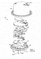
- Electronic utility meter 102 illustrated in FIG. 1 is a known electronic watt-hour meter and may include terminal blades 104, a meter base 106, potential links 108, current transformers 110, a switch 112 to turn on and off service, a metering circuit 114 supported by metering circuit brackets 116, a cover 118 to protect components, and a user button 120 which activates switch 112.
- the various features which may be available to a consumer/user via hardware components such as metering circuit 114, potential links 108, current transformers 110 etc. may be enabled or disabled by feature licenses.
- the invention provides a method for managing a transfer of a feature license between a first utility meter and a second utility meter, communicatively conected to the first utility meter, the method comprising: obtaining feature license data about the first utility meter and the second utility meter; receiving a selection of the feature license to be transferred from the first utility meter to the second utility meter; and transferring the selected feature license from the first utility meter to the second utility meter.
- the invention resides in a computer program comprising computer program code means adapted to perform the steps of the above method when run a computer and in the computer program embodied on a computer-readable medium.
- the invention provides a system including: a network communicatively connected to a first utility meter and a second utility meter; and a computing device communicatively connected to the network, the computing device including the above computer program.
- aspects of the invention provide for systems and devices configured to enable the transfer of feature licenses between utility meters.
- a computing device is configured such that it may connect to either or both of a source utility meter and a destination utility meter. The computing device may, via the connection(s) between the source utility meter and the destination utility meter, allow a user/technician to manage the transfer of a feature license(s) there between.
- the feature license(s) may be transferred via a utility network, a local network, a serial connection, Universal Serial Bus (USB) ports, optical ports, a RadioFrequency (RF) link, a Transmission Control Protocol/Internet Protocol (TCP/IP) connection, a Worldwide Interoperability for Microwave Access (WiMax) connection, or any other form of connection or combination of connections known in the art.
- a utility company and/or user may be able to quickly upgrade and update existing utility meters by directly transferring feature licenses between the existing utility meters.
- utility meters including, e.g., electrical meters, smart meters, power meters, gas meters, etc.
- feature licenses/keys which are obtained/purchased by the utility company from energy meter manufacturers.
- a technician for the utility company may upload or download feature licenses from a utility meter via a memory device.
- feature licenses involves multiple exchanges of data and feature licenses across many devices.
- a memory device as an intermediary for the transport of a feature license between a license pool and a utility meter increases the cost and complexity of the transfer.
- the memory device may be expensive to purchase and maintain, and use of the memory device requires that the feature license be written into and read off of the memory device, complicating the coding process. Additionally, the user/technician is required to oversee each transfer of the feature license and in some cases physically move and/or connect the memory device so as to complete a transfer.
- inventions of the current invention provide for a system which facilitates the transfer of feature licenses directly between utility meters.
- the system includes a computing device which is communicatively connected to a plurality of utility meters.
- the computing device is configured to identify a source utility meter and a destination utility meter, the source utility meter containing a feature license to be transferred to the destination utility meter. Once identified the computing device manages the transfer of the feature license from the source utility meter to the destination utility meter, removing/disabling the feature license from the source utility meter and installing/enabling the feature license on the destination utility meter.
- the coding process is simplified, user/technician involvement is minimized and the use of an intermediary such as a memory device is eliminated.
- the management system described herein may be embodied as a system(s), method(s) or computer program product(s), e.g., as part of a utility network system, utility network, utility meter, etc.
- embodiments of the present invention may take the form of an entirely hardware embodiment, an entirely software embodiment (including firmware, resident software, micro-code, etc.) or an embodiment combining software and hardware aspects that may all generally be referred to herein as a "circuit,” “module,” “network” or “system.”
- the present invention may take the form of a computer program product embodied in any tangible medium of expression having computer-usable program code embodied in the medium.
- the computer-useable or computer-readable medium may be, for example but not limited to, an electronic, magnetic, optical, electromagnetic, infrared, or semiconductor system, apparatus, or device. More specific examples (a non-exhaustive list) of the computer-readable medium would include the following: an electrical connection having one or more wires, a portable computer diskette, a hard disk, a random access memory (RAM), a read-only memory (ROM), an erasable programmable read-only memory (EPROM or Flash memory), an optical fiber, a portable compact disc read-only memory (CD-ROM), an optical storage device, a transmission media such as those supporting the Internet or an intranet, or a magnetic storage device.
- the computer-usable or computer-readable medium could even be paper or another suitable medium upon which the program is printed, as the program can be electronically captured, via, for instance, optical scanning of the paper or other medium, then compiled, interpreted, or otherwise processed in a suitable manner, if necessary, and then stored in a computer memory.
- a computer-usable or computer-readable medium may be any medium that can contain, store, communicate, or transport the program for use by or in connection with the instruction execution system, apparatus, or device.
- the computer-usable medium may include a propagated data signal with the computer-usable program code embodied therewith, either in baseband or as part of a carrier wave.
- the computer usable program code may be transmitted using any appropriate medium, including but not limited to wireless, wireline, optical fiber cable, RF, etc.
- Computer program code for carrying out operations of the present invention may be written in any combination of one or more programming languages, including an object oriented programming language such as Java, Smalltalk, C++ or the like and conventional procedural programming languages, such as the "C" programming language or similar programming languages.
- the program code may execute entirely on the user's computer, partly on the user's computer, as a stand-alone software package, partly on the user's computer and partly on a remote computer or entirely on the remote computer or server.
- the remote computer may be connected to the user's computer through any type of network, including a local area network (LAN) or a wide area network (WAN), or the connection may be made to an external computer (for example, through the Internet using an Internet Service Provider).
- LAN local area network
- WAN wide area network
- Internet Service Provider for example, AT&T, MCI, Sprint, EarthLink, MSN, GTE, etc.
- These computer program instructions may also be stored in a computer-readable medium that can direct a computer or other programmable data processing apparatus to function in a particular manner, such that the instructions stored in the computer-readable medium produce an article of manufacture including instruction means which implement the function/act specified in the block diagram block or blocks.
- the computer program instructions may also be loaded onto a computer or other programmable data processing apparatus to cause a series of operational steps to be performed on the computer or other programmable apparatus to produce a computer implemented process such that the instructions which execute on the computer or other programmable apparatus provide processes for implementing the functions/acts specified in the flowchart and/or block diagram block or blocks.
- a feature license management system facilitates the transfer of feature licenses between a plurality of utility meters.
- Each of the components in the Figures may be connected via conventional means, e.g., via wireless mesh, WiFi, power-line communication, cellular, radio-frequency link, WiMax, optical port, USB port or other known means as is indicated in the Figs. 2-6 .
- a schematic illustration of an embodiment of a feature license management system 200 is shown.
- Feature license management system 200 may include a management system 207 disposed on a computing device 210 which is communicatively connected to a utility meter 222 and a utility meter 224.
- Utility meter 222 and utility meter 224 may comprise an electrical meter, a water meter, a gas meter, a smart meter or any other form of utility meter as is known in the art.
- Utility meter 222 and utility meter 224 may or may not be interconnected via a coupling, network, communication channel etc.
- Management system 207 may direct computing device 210 to select utility meter 222 as a source and identify a feature license 230 on utility meter 222 to transfer to utility meter 224.
- Feature license 230 may include a set of distinct or interrelated feature licenses/keys.
- Computing device 210 may then transfer feature license 230 from utility meter 222 to utility meter 224.
- computing device 210 may use a Network 220 to transfer or enable the transfer of feature license 230 from utility meter 222 to utility meter 224. In one embodiment, computing device 210 may directly transfer feature license 230 from utility meter 222 to utility meter 224 via Network 220.
- Network 220 may include any of an Advanced Metering Infrastructure (AMI), a utility network, a Neighborhood Area Network (NAN), a Local Area Network (LAN) or any other form of network as is known in the art.
- AMI Advanced Metering Infrastructure
- NAN Neighborhood Area Network
- LAN Local Area Network
- computing device 210 may disable feature license 230 on utility meter 222 and enable feature license 230 on utility meter 224.
- computing device 210 may include a user interface (UI) 212.
- UI 212 may be generated by management system 207.
- UI 212 may include a Graphical User Interface (GUI).
- GUI Graphical User Interface
- a user may, via UI 212, select source utility meter 222 and destination utility meter 224 by inputting the respective address of each utility meter or by selecting each utility meter from a database of available utility meters.
- computing device 210 may display on UI 212 feature licenses 230 installed on either or both of utility meter 222 and utility meter 224.
- computing device 210 may comparatively display on UI 212 all feature licenses 230 on both of utility meter 222 and utility meter 224, listing the feature licenses 230 side by side for a user to view and compare.
- computing device 210 may provide to a user via UI 212 the option to select feature license 230 to be transferred from utility meter 222 to utility meter 224.
- computing device 210 may receive a user selection via UI 212 and transfer feature license 230 in response to the user selection.
- computing device 210 enables a prompt on UI 212 to confirm transfer of feature license 230 between utility meter 222 and utility meter 224 before transferring feature license 230.
- UI 212 displays the updated feature licenses 230 on utility meter 222 and utility meter 224.
- computing device 210 may transfer feature license 230 between any of a utility meter 226, a utility meter 228, utility meter 222 and utility meter 224.
- any of utility meter 222, utility meter 224, utility meter 226 and utility meter 228 may display feature licenses 230 contained thereon.
- UI 212 may enable a user to select any number of feature licenses 230 to be transferred between any of utility meter 226, utility meter 228, utility meter 222 and utility meter 224.
- UI 212 may be located remote relative to computing device 210.
- UI 212 and computing device 210 may be located remote relative to any of utility meter 226, utility meter 228, utility meter 222 and utility meter 224.
- computing device 210 and UI 212 may be located at utility meter 222 and be configured to manage transfers of feature license 230 to any of utility meter 224, utility meter 226 and utility meter 228. It is understood that each utility meter 222, 224, 226 and 228 may be connected to network 220 and/or each other via the same or substantially different communication paths/communication mediums in the software (e.g. serial communication, TCP/IP communication, etc.).
- computing device 210 can comprise any general purpose computing article of manufacture capable of executing computer program code installed by a user (e.g., a personal computer, server, handheld device, etc.).
- computing device 210, graphical user interface 212, utility meter 226, utility meter 228, utility meter 222 and utility meter 224 are only representative of various possible equivalent computing devices that may perform the various process steps of the disclosure.
- computing device 210 can comprise any specific purpose computing article of manufacture comprising hardware and/or computer program code for performing specific functions, any computing article of manufacture that comprises a combination of specific purpose and general purpose hardware/software, or the like.
- the program code and hardware can be created using standard programming and engineering techniques, respectively.
- a management system is initiated on computing device 210 to begin a transfer of feature license 230 between any of utility meter 222, 224, 226 and 228. That is, either a scheduled transfer or a user-commanded transfer may be performed by computing device 210 in response to a prompt to transfer feature license 230 between any of utility meter 222, 224, 226 and 228.
- computing device 210 connects with a first utility meter 222, first utility meter 222 to serve as a source utility meter 222.
- computing device 210 connects with a second utility meter 224, the second utility meter 224 to serve as a destination utility meter 224.
- First utility meter 222 and second utility meter 224 may be chosen as source and destination meters respectively based on any of a computer database, user knowledge, an inventory query, a feature license log or any other form of feature license tracking system as is known.
- First utility meter 222 may be identified as the source meter because meter license 230 is to be removed therefrom and installed on the destination meter, second utility meter 224.
- computing device 210 obtains feature license data including but not limited to feature license identification, feature license activation state (enabled or disabled), feature license compatibility, a meter(s) configuration table, a software configuration table, etc., from and reads the feature licenses 230 on first utility meter 222 and second utility meter 224. That is, computing device 210 communicates with first utility meter 222 and second utility meter 224 to obtain data for feature licenses 230 installed on each utility meter. After process P3, in process P4, computing device 210 displays feature licenses 230 installed on either or both of first utility meter 222 and second utility meter 224 on UI 212. Following process P4, in process P5, computing device 210 provides an option or prompt on UI 212 for a user to select a feature license 230 to transfer from first utility meter 222 to second utility meter 224.
- feature license data including but not limited to feature license identification, feature license activation state (enabled or disabled), feature license compatibility, a meter(s) configuration table,
- a user selects feature license 230 to transfer from first utility meter 222 to second utility meter 224.
- the user may select feature license 230 by checking a box graphically displayed next to feature license 230 on UI 212.
- computing device 210 may provide a confirmation prompt on UI 212, the confirmation prompt for user confirmation of the transfer.
- process P8 user confirms the transfer of feature license 230.
- computing device 210 disables feature license 230 on first utility meter 222 and enables feature license 230 on second utility meter 224.
- feature license 230 may be first disabled on first utility meter 222 and then enabled on second utility meter 224. In another embodiment, feature license 230 may be first enabled on second utility meter 224 and then disabled on first utility meter 222. In another embodiment, feature license 230 may be substantially simultaneously disabled on first utility meter 222 and enabled on second utility meter 224. In any event, following process P9, in process P10, computing device 210 displays the updated feature licenses of first utility meter 222 and second utility meter 224 on UI 212. After process P10, in process P11, the program ends.
- each block in the flowchart or block diagrams may represent a module, segment, or portion of code, which comprises one or more executable instructions for implementing the specified logical function(s).
- the functions noted in the block may occur out of the order noted in the Figures. For example, two blocks shown in succession may, in fact, be executed substantially concurrently, or the blocks may sometimes be executed in the reverse order, depending upon the functionality involved.
- FIG. 4 an illustrative environment 400 including a management system 207 is shown according to embodiments of the invention.
- Environment 400 includes a computer infrastructure 402 that can perform the various processes described herein.
- computer infrastructure 402 is shown including computing device 210 which includes management system 207, which enables computing device 210 to manage transfers of feature licenses between utility meter 222 and utility meter 224 by performing the process steps of the disclosure.
- management system 207 has the technical effect of enabling computing device 210 to perform, among other things, the feature license management functions described herein. It is understood that some of the various components shown in Fig. 4 can be implemented independently, combined, and/or stored in memory for one or more separate computing devices that are included in computing device 210. Further, it is understood that some of the components and/or functionality may not be implemented, or additional schemas and/or functionality may be included as part of feature license management system 200.
- Computing device 210 is shown including a memory 412, a processor unit (PU) 414, an input/output (I/O) interface 416, and a bus 418. Further, computing device 210 is shown in communication with an external I/O device/resource 420 and a storage system 422.
- processor 414 executes computer program code, such as management system 207, that is stored in memory 412 and/or storage system 422. While executing computer program code, processor 414 can read and/or write data, such as graphical user interface 430 and/or feature license data 434, to/from memory 412, storage system 422, and/or I/O interface 416.
- Bus 418 provides a communications link between each of the components in computing device 210.
- I/O device 420 can comprise any device that enables a user to interact with computing device 210 or any device that enables computing device 210 to communicate with one or more other computing devices.
- Input/output devices (including but not limited to keyboards, displays, pointing devices, etc.) can be coupled to the system either directly or through intervening I/O controllers.
- environment 400 may optionally include utility meter 222, utility meter 224 and network 220 communicatively connected to management system 207 through computing device 210 (e.g., via wireless or hardwired means).
- computing device 210 and/or management system 207 may be disposed upon or within utility meter 222 and/or utility meter 224.
- UI 500 includes a first meter identification field 502 for the source utility meter and a second meter identification field 504 for the destination utility meter, identification field 502 and identification field 504 for displaying which utility meters computing device 210 is connected to. These fields may display the meter IP address, meter ID, meter serial number or other known identifying features as are known.
- a feature license list window 522 and a feature license list window 524 may be disposed beneath identification field 502 and identification field 504 on UI 500.
- Feature license list windows 522 and 524 display the feature license contents of the utility meters connected to computing device 210.
- feature license list windows 522 and 524 of Fig. 5 are exemplary, and that feature license list windows 522 and 524 may display any feature license known.
- Feature license selection boxes 528 may be included in either or both of feature license list window 522 and feature license list window 524, feature license selection boxes 528 may be disposed beside each feature license contained on the respective utility meters. Feature license selection boxes 528 for enabling a user to individually select a feature license to be transferred.
- UI 500 may further include feature license add command button 512, feature license remove command button 516, reload command button 514 and commit changes command button 518. Add command button 512 and remove command button 516 for moving feature licenses between meters and list windows 522 and 524.
- UI 600 User Interface 600 is shown according to embodiments of the invention.
- UI 600 shows feature license list window 522 and feature license list window 524 after a transfer has been completed between the source utility meter and the destination utility meter.
- the feature license management system of the present disclosure is not limited to any one particular meter, electrical meter, smart meter, network or other system, and may be used with other power and communication systems. Additionally, the feature license management system of the present invention may be used with other systems not described herein that may benefit from the simplified, secure, direct transfer of feature licenses provided by the feature license management system described herein.
- various systems and components are described as “obtaining” and/or “transferring” data (e.g., firmware, feature license, feature key, software, etc.). It is understood that the corresponding data can be obtained using any solution.
- the corresponding system/component can generate and/or be used to generate the data, retrieve the data from one or more data stores or sensors (e.g., a database), receive the data from another system/component, and/or the like.
- the data is not generated by the particular system/component, it is understood that another system/component can be implemented apart from the system/component shown, which generates the data and provides it to the system/component and/or stores the data for access by the system/component.
Abstract
Description
- The subject matter disclosed herein relates generally to meter technology, and more particularly, to a management system for the transfer of feature licenses between utility meters.
- Some utility companies, for example, certain electrical or gas service companies, employ utility meters to regulate and/or record the amount of service (e.g. electricity) being consumed by a given location or consumer. The design of these utility meters includes numerous hardware/firmware components which increase meter functionality and versatility, providing a variety of features to the consumer and the utility. Access to and use of these components, and the features they provide, is limited and/or controlled on each utility meter by feature licenses, feature keys, soft keys, soft switches etc. These feature licenses generally include firmware which is installed on the utility meter to enable use (i.e. authorized access, appropriate payment for feature access, etc.) of the varied features available on each utility meter. However, maintenance and installation of feature licenses includes the use of a license pool from which licenses are exchanged onto memory devices to be selectively uploaded onto each utility meter. The memory devices, such as smart cards/hardware dongles, serve as intermediaries in the feature license transfer process. A smart card obtains a feature license from the license pool and then is physically brought to a location to transfer the feature license on to the utility meter via software and a smartcard reader. The multiple steps and intermediate devices required in the current feature license transfer process may serve to slow, complicate and increase the cost of a transfer.
- Referring to
FIG. 1 , a schematic view of a knownelectronic utility meter 102 is shown with hardware components.Electronic utility meter 102 illustrated inFIG. 1 is a known electronic watt-hour meter and may includeterminal blades 104, ameter base 106,potential links 108,current transformers 110, aswitch 112 to turn on and off service, ametering circuit 114 supported bymetering circuit brackets 116, acover 118 to protect components, and auser button 120 which activatesswitch 112. The various features which may be available to a consumer/user via hardware components such asmetering circuit 114,potential links 108,current transformers 110 etc. may be enabled or disabled by feature licenses. - Systems and devices for managing a transfer of feature licenses between utility meters are disclosed. In a first aspect, the invention provides a method for managing a transfer of a feature license between a first utility meter and a second utility meter, communicatively conected to the first utility meter, the method comprising: obtaining feature license data about the first utility meter and the second utility meter; receiving a selection of the feature license to be transferred from the first utility meter to the second utility meter; and transferring the selected feature license from the first utility meter to the second utility meter.
- In a second aspect, the invention resides in a computer program comprising computer program code means adapted to perform the steps of the above method when run a computer and in the computer program embodied on a computer-readable medium.
- In a third aspect, the invention provides a system including: a network communicatively connected to a first utility meter and a second utility meter; and a computing device communicatively connected to the network, the computing device including the above computer program.
- Embodiments of the present invention will now be described, by way of example only, with reference to the accompanying drawings in which:
-
Fig. 1 shows a schematic illustration of a known electrical utility meter. -
Fig. 2 shows a schematic illustration of an environment including a management system in accordance with an embodiment of the invention. -
Fig. 3 shows a method flow diagram illustrating a process according to embodiments of the invention. -
Fig. 4 shows a schematic illustration of an environment including a management system in accordance with an embodiment of the invention. -
Fig. 5 shows a schematic illustration of a user interface according to embodiments of the invention. -
Fig. 6 shows a schematic illustration of a user interface according to embodiments of the invention. - It is noted that the drawings of the disclosure are not necessarily to scale. The drawings are intended to depict only typical aspects of the disclosure, and therefore should not be considered as limiting the scope of the disclosure. In the drawings, like numbering represents like elements between the drawings.
- As indicated above, aspects of the invention provide for systems and devices configured to enable the transfer of feature licenses between utility meters. A computing device is configured such that it may connect to either or both of a source utility meter and a destination utility meter. The computing device may, via the connection(s) between the source utility meter and the destination utility meter, allow a user/technician to manage the transfer of a feature license(s) there between. The feature license(s) may be transferred via a utility network, a local network, a serial connection, Universal Serial Bus (USB) ports, optical ports, a RadioFrequency (RF) link, a Transmission Control Protocol/Internet Protocol (TCP/IP) connection, a Worldwide Interoperability for Microwave Access (WiMax) connection, or any other form of connection or combination of connections known in the art. As a result of utilizing aspects of the invention a utility company and/or user may be able to quickly upgrade and update existing utility meters by directly transferring feature licenses between the existing utility meters.
- In the art of metered services and systems, utility meters (including, e.g., electrical meters, smart meters, power meters, gas meters, etc.) are used to track and record service consumption. Recently, the features and functions available on these utility meters have begun to increase. Access to these features is controlled on each utility meter by feature licenses/keys which are obtained/purchased by the utility company from energy meter manufacturers. In response to a change in the service plan of a consumer/user, a technician for the utility company may upload or download feature licenses from a utility meter via a memory device. Thereby, enabling or disabling specific features and functions on the utility meter. However, the transfer of feature licenses involves multiple exchanges of data and feature licenses across many devices. The use of a memory device as an intermediary for the transport of a feature license between a license pool and a utility meter increases the cost and complexity of the transfer. The memory device may be expensive to purchase and maintain, and use of the memory device requires that the feature license be written into and read off of the memory device, complicating the coding process. Additionally, the user/technician is required to oversee each transfer of the feature license and in some cases physically move and/or connect the memory device so as to complete a transfer.
- In contrast to the conventional system, embodiments of the current invention provide for a system which facilitates the transfer of feature licenses directly between utility meters. The system includes a computing device which is communicatively connected to a plurality of utility meters. The computing device is configured to identify a source utility meter and a destination utility meter, the source utility meter containing a feature license to be transferred to the destination utility meter. Once identified the computing device manages the transfer of the feature license from the source utility meter to the destination utility meter, removing/disabling the feature license from the source utility meter and installing/enabling the feature license on the destination utility meter. As the feature license is transferred directly between utility meters, the coding process is simplified, user/technician involvement is minimized and the use of an intermediary such as a memory device is eliminated.
- As will be appreciated by one skilled in the art, the management system described herein may be embodied as a system(s), method(s) or computer program product(s), e.g., as part of a utility network system, utility network, utility meter, etc. Accordingly, embodiments of the present invention may take the form of an entirely hardware embodiment, an entirely software embodiment (including firmware, resident software, micro-code, etc.) or an embodiment combining software and hardware aspects that may all generally be referred to herein as a "circuit," "module," "network" or "system." Furthermore, the present invention may take the form of a computer program product embodied in any tangible medium of expression having computer-usable program code embodied in the medium.
- Any combination of one or more computer usable or computer readable medium(s) may be utilized. The computer-useable or computer-readable medium may be, for example but not limited to, an electronic, magnetic, optical, electromagnetic, infrared, or semiconductor system, apparatus, or device. More specific examples (a non-exhaustive list) of the computer-readable medium would include the following: an electrical connection having one or more wires, a portable computer diskette, a hard disk, a random access memory (RAM), a read-only memory (ROM), an erasable programmable read-only memory (EPROM or Flash memory), an optical fiber, a portable compact disc read-only memory (CD-ROM), an optical storage device, a transmission media such as those supporting the Internet or an intranet, or a magnetic storage device. Note that the computer-usable or computer-readable medium could even be paper or another suitable medium upon which the program is printed, as the program can be electronically captured, via, for instance, optical scanning of the paper or other medium, then compiled, interpreted, or otherwise processed in a suitable manner, if necessary, and then stored in a computer memory. In the context of this document, a computer-usable or computer-readable medium may be any medium that can contain, store, communicate, or transport the program for use by or in connection with the instruction execution system, apparatus, or device. The computer-usable medium may include a propagated data signal with the computer-usable program code embodied therewith, either in baseband or as part of a carrier wave. The computer usable program code may be transmitted using any appropriate medium, including but not limited to wireless, wireline, optical fiber cable, RF, etc.
- Computer program code for carrying out operations of the present invention may be written in any combination of one or more programming languages, including an object oriented programming language such as Java, Smalltalk, C++ or the like and conventional procedural programming languages, such as the "C" programming language or similar programming languages. The program code may execute entirely on the user's computer, partly on the user's computer, as a stand-alone software package, partly on the user's computer and partly on a remote computer or entirely on the remote computer or server. In the latter scenario, the remote computer may be connected to the user's computer through any type of network, including a local area network (LAN) or a wide area network (WAN), or the connection may be made to an external computer (for example, through the Internet using an Internet Service Provider).
- These computer program instructions may also be stored in a computer-readable medium that can direct a computer or other programmable data processing apparatus to function in a particular manner, such that the instructions stored in the computer-readable medium produce an article of manufacture including instruction means which implement the function/act specified in the block diagram block or blocks.
- The computer program instructions may also be loaded onto a computer or other programmable data processing apparatus to cause a series of operational steps to be performed on the computer or other programmable apparatus to produce a computer implemented process such that the instructions which execute on the computer or other programmable apparatus provide processes for implementing the functions/acts specified in the flowchart and/or block diagram block or blocks.
- Turning to the figures, embodiments of a feature license management system are shown, where the feature license management system facilitates the transfer of feature licenses between a plurality of utility meters. Each of the components in the Figures may be connected via conventional means, e.g., via wireless mesh, WiFi, power-line communication, cellular, radio-frequency link, WiMax, optical port, USB port or other known means as is indicated in the
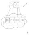
Figs. 2-6 . Specifically, referring toFig. 2 , a schematic illustration of an embodiment of a featurelicense management system 200 is shown. Featurelicense management system 200 may include amanagement system 207 disposed on acomputing device 210 which is communicatively connected to autility meter 222 and autility meter 224.Utility meter 222 andutility meter 224 may comprise an electrical meter, a water meter, a gas meter, a smart meter or any other form of utility meter as is known in the art.Utility meter 222 andutility meter 224 may or may not be interconnected via a coupling, network, communication channel etc.Management system 207 may directcomputing device 210 to selectutility meter 222 as a source and identify afeature license 230 onutility meter 222 to transfer toutility meter 224.Feature license 230 may include a set of distinct or interrelated feature licenses/keys.Computing device 210 may then transferfeature license 230 fromutility meter 222 toutility meter 224. In one embodiment,computing device 210 may use aNetwork 220 to transfer or enable the transfer offeature license 230 fromutility meter 222 toutility meter 224. In one embodiment,computing device 210 may directly transferfeature license 230 fromutility meter 222 toutility meter 224 viaNetwork 220.Network 220 may include any of an Advanced Metering Infrastructure (AMI), a utility network, a Neighborhood Area Network (NAN), a Local Area Network (LAN) or any other form of network as is known in the art. In this embodiment of the invention,computing device 210 may disablefeature license 230 onutility meter 222 and enablefeature license 230 onutility meter 224. - In an embodiment of the present invention,
computing device 210 may include a user interface (UI) 212. In one embodiment,UI 212 may be generated bymanagement system 207.UI 212 may include a Graphical User Interface (GUI). In one embodiment, a user may, viaUI 212, selectsource utility meter 222 anddestination utility meter 224 by inputting the respective address of each utility meter or by selecting each utility meter from a database of available utility meters. In one embodiment,computing device 210 may display onUI 212feature licenses 230 installed on either or both ofutility meter 222 andutility meter 224. In another embodiment,computing device 210 may comparatively display onUI 212 all feature licenses 230 on both ofutility meter 222 andutility meter 224, listing the feature licenses 230 side by side for a user to view and compare. In one embodiment,computing device 210 may provide to a user viaUI 212 the option to selectfeature license 230 to be transferred fromutility meter 222 toutility meter 224. In one embodiment,computing device 210 may receive a user selection viaUI 212 andtransfer feature license 230 in response to the user selection. In another embodiment,computing device 210 enables a prompt onUI 212 to confirm transfer offeature license 230 betweenutility meter 222 andutility meter 224 before transferringfeature license 230. In another embodiment,UI 212 displays the updated feature licenses 230 onutility meter 222 andutility meter 224. In another embodiment,computing device 210 may transferfeature license 230 between any of autility meter 226, autility meter 228,utility meter 222 andutility meter 224. In one embodiment, any ofutility meter 222,utility meter 224,utility meter 226 andutility meter 228 may display feature licenses 230 contained thereon. In another embodiment,UI 212 may enable a user to select any number offeature licenses 230 to be transferred between any ofutility meter 226,utility meter 228,utility meter 222 andutility meter 224. In one embodiment,UI 212 may be located remote relative tocomputing device 210. In another embodiment,UI 212 andcomputing device 210 may be located remote relative to any ofutility meter 226,utility meter 228,utility meter 222 andutility meter 224. In another embodiment,computing device 210 andUI 212 may be located atutility meter 222 and be configured to manage transfers offeature license 230 to any ofutility meter 224,utility meter 226 andutility meter 228. It is understood that eachutility meter - In any event,
computing device 210 can comprise any general purpose computing article of manufacture capable of executing computer program code installed by a user (e.g., a personal computer, server, handheld device, etc.). However, it is understood thatcomputing device 210,graphical user interface 212,utility meter 226,utility meter 228,utility meter 222 andutility meter 224 are only representative of various possible equivalent computing devices that may perform the various process steps of the disclosure. To this extent, in other embodiments,computing device 210 can comprise any specific purpose computing article of manufacture comprising hardware and/or computer program code for performing specific functions, any computing article of manufacture that comprises a combination of specific purpose and general purpose hardware/software, or the like. In each case, the program code and hardware can be created using standard programming and engineering techniques, respectively. - Turning to
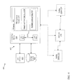
Fig. 3 , an illustrative method flow diagram is shown according to embodiments of the invention: In pre-process P0, a management system is initiated oncomputing device 210 to begin a transfer offeature license 230 between any ofutility meter device 210 in response to a prompt to transferfeature license 230 between any ofutility meter computing device 210 connects with afirst utility meter 222,first utility meter 222 to serve as asource utility meter 222. Following process P1, in process P2,computing device 210 connects with asecond utility meter 224, thesecond utility meter 224 to serve as adestination utility meter 224.First utility meter 222 andsecond utility meter 224 may be chosen as source and destination meters respectively based on any of a computer database, user knowledge, an inventory query, a feature license log or any other form of feature license tracking system as is known.First utility meter 222 may be identified as the source meter becausemeter license 230 is to be removed therefrom and installed on the destination meter,second utility meter 224. Following process P2, in process P3,computing device 210 obtains feature license data including but not limited to feature license identification, feature license activation state (enabled or disabled), feature license compatibility, a meter(s) configuration table, a software configuration table, etc., from and reads the feature licenses 230 onfirst utility meter 222 andsecond utility meter 224. That is,computing device 210 communicates withfirst utility meter 222 andsecond utility meter 224 to obtain data forfeature licenses 230 installed on each utility meter. After process P3, in process P4,computing device 210 displays featurelicenses 230 installed on either or both offirst utility meter 222 andsecond utility meter 224 onUI 212. Following process P4, in process P5,computing device 210 provides an option or prompt onUI 212 for a user to select afeature license 230 to transfer fromfirst utility meter 222 tosecond utility meter 224. - After process P5, in process P6, a user selects
feature license 230 to transfer fromfirst utility meter 222 tosecond utility meter 224. In one embodiment the user may selectfeature license 230 by checking a box graphically displayed next to featurelicense 230 onUI 212. Following process P6, in process P7, once a user selects afeature license 230 to transfer,computing device 210 may provide a confirmation prompt onUI 212, the confirmation prompt for user confirmation of the transfer. Following process P7, in process P8, user confirms the transfer offeature license 230. After process P8, in process P9,computing device 210 disablesfeature license 230 onfirst utility meter 222 and enablesfeature license 230 onsecond utility meter 224. In one embodiment,feature license 230 may be first disabled onfirst utility meter 222 and then enabled onsecond utility meter 224. In another embodiment,feature license 230 may be first enabled onsecond utility meter 224 and then disabled onfirst utility meter 222. In another embodiment,feature license 230 may be substantially simultaneously disabled onfirst utility meter 222 and enabled onsecond utility meter 224. In any event, following process P9, in process P10,computing device 210 displays the updated feature licenses offirst utility meter 222 andsecond utility meter 224 onUI 212. After process P10, in process P11, the program ends. - The data flow diagram and block diagrams in the Figures illustrate the architecture, functionality, and operation of possible implementations of systems, methods and computer program products according to various embodiments of the present invention. In this regard, each block in the flowchart or block diagrams may represent a module, segment, or portion of code, which comprises one or more executable instructions for implementing the specified logical function(s). It should also be noted that, in some alternative implementations, the functions noted in the block may occur out of the order noted in the Figures. For example, two blocks shown in succession may, in fact, be executed substantially concurrently, or the blocks may sometimes be executed in the reverse order, depending upon the functionality involved. It will also be noted that each block of the block diagrams and/or flowchart illustration, and combinations of blocks in the block diagrams and/or flowchart illustration, can be implemented by special purpose hardware-based systems that perform the specified functions or acts, or combinations of special purpose hardware and computer instructions.
- Turning to
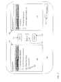
Fig. 4 , anillustrative environment 400 including amanagement system 207 is shown according to embodiments of the invention.Environment 400 includes acomputer infrastructure 402 that can perform the various processes described herein. In particular,computer infrastructure 402 is shown includingcomputing device 210 which includesmanagement system 207, which enablescomputing device 210 to manage transfers of feature licenses betweenutility meter 222 andutility meter 224 by performing the process steps of the disclosure. - As previously mentioned and discussed further below,
management system 207 has the technical effect of enablingcomputing device 210 to perform, among other things, the feature license management functions described herein. It is understood that some of the various components shown inFig. 4 can be implemented independently, combined, and/or stored in memory for one or more separate computing devices that are included incomputing device 210. Further, it is understood that some of the components and/or functionality may not be implemented, or additional schemas and/or functionality may be included as part of featurelicense management system 200. -
Computing device 210 is shown including amemory 412, a processor unit (PU) 414, an input/output (I/O) interface 416, and abus 418. Further,computing device 210 is shown in communication with an external I/O device/resource 420 and astorage system 422. As is known in the art, in general,processor 414 executes computer program code, such asmanagement system 207, that is stored inmemory 412 and/orstorage system 422. While executing computer program code,processor 414 can read and/or write data, such as graphical user interface 430 and/orfeature license data 434, to/frommemory 412,storage system 422, and/or I/O interface 416.Bus 418 provides a communications link between each of the components incomputing device 210. I/O device 420 can comprise any device that enables a user to interact withcomputing device 210 or any device that enablescomputing device 210 to communicate with one or more other computing devices. Input/output devices (including but not limited to keyboards, displays, pointing devices, etc.) can be coupled to the system either directly or through intervening I/O controllers. - In some embodiments, as shown in
Fig. 4 ,environment 400 may optionally includeutility meter 222,utility meter 224 andnetwork 220 communicatively connected tomanagement system 207 through computing device 210 (e.g., via wireless or hardwired means). In some embodiments,computing device 210 and/ormanagement system 207 may be disposed upon or withinutility meter 222 and/orutility meter 224. - Turning to
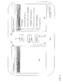
Fig. 5 , a schematic illustration of a User Interface (UI) 500 is shown according to embodiments of the invention.UI 500 includes a firstmeter identification field 502 for the source utility meter and a secondmeter identification field 504 for the destination utility meter,identification field 502 andidentification field 504 for displaying which utilitymeters computing device 210 is connected to. These fields may display the meter IP address, meter ID, meter serial number or other known identifying features as are known. A featurelicense list window 522 and a featurelicense list window 524 may be disposed beneathidentification field 502 andidentification field 504 onUI 500. Featurelicense list windows computing device 210. It is understood that the feature licenses shown in featurelicense list windows Fig. 5 are exemplary, and that featurelicense list windows license selection boxes 528 may be included in either or both of featurelicense list window 522 and featurelicense list window 524, featurelicense selection boxes 528 may be disposed beside each feature license contained on the respective utility meters. Featurelicense selection boxes 528 for enabling a user to individually select a feature license to be transferred.UI 500 may further include feature license addcommand button 512, feature license removecommand button 516, reloadcommand button 514 and commitchanges command button 518. Addcommand button 512 and removecommand button 516 for moving feature licenses between meters andlist windows command button 518 to confirm/perform a transfer offeature license 230 between utility meters. Reloadcommand button 514 for refreshing featurelicense list window 522 and featurelicense list window 524. These commands enable a user to transfer selected feature licenses between utility meters. InFig. 5 , a variety of feature licenses are shown installed on both a source utility meter and a destination utility meter before being transferred between the utility meters. These feature licenses being distributed among the utility meters and displayed in featurelicense list window 522 and featurelicense list window 524. Turning toFigure 6 , a schematic illustration of User Interface (UI) 600 is shown according to embodiments of the invention.UI 600 shows featurelicense list window 522 and featurelicense list window 524 after a transfer has been completed between the source utility meter and the destination utility meter. - The feature license management system of the present disclosure is not limited to any one particular meter, electrical meter, smart meter, network or other system, and may be used with other power and communication systems. Additionally, the feature license management system of the present invention may be used with other systems not described herein that may benefit from the simplified, secure, direct transfer of feature licenses provided by the feature license management system described herein.
- As discussed herein, various systems and components are described as "obtaining" and/or "transferring" data (e.g., firmware, feature license, feature key, software, etc.). It is understood that the corresponding data can be obtained using any solution. For example, the corresponding system/component can generate and/or be used to generate the data, retrieve the data from one or more data stores or sensors (e.g., a database), receive the data from another system/component, and/or the like. When the data is not generated by the particular system/component, it is understood that another system/component can be implemented apart from the system/component shown, which generates the data and provides it to the system/component and/or stores the data for access by the system/component.
- The terminology used herein is for the purpose of describing particular embodiments only and is not intended to be limiting of the disclosure. As used herein, the singular forms "a", "an" and "the" are intended to include the plural forms as well, unless the context clearly indicates otherwise. It will be further understood that the terms "comprises" and/or "comprising," when used in this specification, specify the presence of stated features, integers, steps, operations, elements, and/or components, but do not preclude the presence or addition of one or more other features, integers, steps, operations, elements, components, and/or groups thereof.
- This written description uses examples to disclose the invention, including the best mode, and also to enable any person skilled in the art to practice the invention, including making and using any devices or systems and performing any incorporated methods. The patentable scope of the invention is defined by the claims, and may include other examples that occur to those skilled in the art. Such other examples are intended to be within the scope of the claims if they have structural elements that do not differ from the literal language of the claims, or if they include equivalent structural elements with insubstantial differences from the literal languages of the claims.
Claims (9)
- A method for managing a transfer of a feature license (230) between a first utility meter (102, 222, 224, 226, 228) and a second utility meter (102, 222, 224, 226, 228) communicatively coupled to the first utility meter, the method comprising:obtaining feature license data (434) about the first utility meter (102, 222, 224, 226, 228) and the second utility meter (102, 222, 224, 226, 228);receiving a selection of the feature license (230) to be transferred from the first utility meter (102, 222, 224, 226, 228) to the second utility meter (102, 222, 224, 226, 228); andtransferring the selected feature license (230) from the first utility meter (102, 222, 224, 226, 228) to the second utility meter (102, 222, 224, 226, 228).
- The method of claim 1, wherein the feature license (230) is directly transferred from the first utility meter (102, 222, 224, 226, 228) to the second utility meter (102, 222, 224, 226, 228) via a utility network (220).
- The method of claim 1 or 2, wherein the transferring of the feature license (230) from the first utility meter (102, 222, 224, 226, 228) to the second utility meter (102, 222, 224, 226, 228) further includes:disabling the selected feature license (230) on the first utility meter (102, 222, 224, 226, 228); andenabling the selected feature license (230) on the second utility meter (102, 222, 224, 226, 228).
- The method of any of claims 1 to 3, wherein the receiving a selection of the feature license (230) to be transferred from the first utility meter (102, 222, 224, 226, 228) to the second utility meter (102, 222, 224, 226, 228) further includes:displaying on a user interface (212, 416, 420, 430, 500, 600) a first set of feature licenses (230) installed on the first utility meter (102, 222, 224, 226, 228);displaying on the user interface (212, 416, 420, 430, 500, 600) a second set of feature licenses (230) installed on the second utility meter (102, 222, 224, 226, 228); andprompting a user to select the feature license (230) to be transferred from the first utility meter (102, 222, 224, 226, 228) to the second utility meter (102, 222, 224, 226, 228).
- The method of claim 4, further comprising comparatively displaying on the user interface (212, 416, 420, 430, 500, 600) any feature licenses (230) enabled on the first utility meter (102, 222, 224, 226, 228) and any feature licenses (230) enabled on the second utility meter (102, 222, 224, 226, 228).
- The method of any preceding claim, further comprising transfering a plurality of feature licenses (230) between the first utility meter (102, 222, 224, 226, 228) and the second utility meter (102, 222, 224, 226, 228).
- A computer program comprising computer program code means adapted to perform the steps of the method of any of claims 1 to 6, when run on a computer.
- The computer program of claim 7, embodied on a computer-readable medium.
- A system (200, 207, 400, 402) comprising:a network (220) communicatively connected to a first utility meter (102, 222, 224, 226, 228) and a second utility meter (102, 222, 224, 226, 228); anda computing device (210, 400, 402, 414) communicatively connected to the network (220), the computing device (210, 400, 402, 414) adapted to directly transfer a feature license (230) between the first utility meter (102, 222, 224, 226, 228) and the second utility meter (102, 222, 224, 226, 228), the computer device including the computer program of claim 8.
Applications Claiming Priority (1)
| Application Number | Priority Date | Filing Date | Title |
|---|---|---|---|
| US13/105,273 US8812979B2 (en) | 2011-05-11 | 2011-05-11 | Feature license management system |
Publications (3)
| Publication Number | Publication Date |
|---|---|
| EP2523142A2 true EP2523142A2 (en) | 2012-11-14 |
| EP2523142A3 EP2523142A3 (en) | 2014-02-05 |
| EP2523142B1 EP2523142B1 (en) | 2018-03-21 |
Family
ID=46148627
Family Applications (1)
| Application Number | Title | Priority Date | Filing Date |
|---|---|---|---|
| EP12167386.7A Active EP2523142B1 (en) | 2011-05-11 | 2012-05-09 | Feature license management system |
Country Status (4)
| Country | Link |
|---|---|
| US (1) | US8812979B2 (en) |
| EP (1) | EP2523142B1 (en) |
| JP (1) | JP6086658B2 (en) |
| ES (1) | ES2668786T3 (en) |
Cited By (1)
| Publication number | Priority date | Publication date | Assignee | Title |
|---|---|---|---|---|
| WO2020142536A1 (en) * | 2018-12-31 | 2020-07-09 | Itron, Inc. | Application management service |
Families Citing this family (19)
| Publication number | Priority date | Publication date | Assignee | Title |
|---|---|---|---|---|
| US7747733B2 (en) | 2004-10-25 | 2010-06-29 | Electro Industries/Gauge Tech | Power meter having multiple ethernet ports |
| JP5034109B2 (en) * | 2007-11-01 | 2012-09-26 | Necインフロンティア株式会社 | License management apparatus, license management method, and license authentication program |
| US10275840B2 (en) | 2011-10-04 | 2019-04-30 | Electro Industries/Gauge Tech | Systems and methods for collecting, analyzing, billing, and reporting data from intelligent electronic devices |
| US10862784B2 (en) | 2011-10-04 | 2020-12-08 | Electro Industries/Gauge Tech | Systems and methods for processing meter information in a network of intelligent electronic devices |
| US10771532B2 (en) | 2011-10-04 | 2020-09-08 | Electro Industries/Gauge Tech | Intelligent electronic devices, systems and methods for communicating messages over a network |
| US10303860B2 (en) * | 2011-10-04 | 2019-05-28 | Electro Industries/Gauge Tech | Security through layers in an intelligent electronic device |
| US11816465B2 (en) | 2013-03-15 | 2023-11-14 | Ei Electronics Llc | Devices, systems and methods for tracking and upgrading firmware in intelligent electronic devices |
| US11328344B2 (en) * | 2013-05-31 | 2022-05-10 | Itron, Inc. | Utility application delivery platform |
| US9342288B2 (en) * | 2013-05-31 | 2016-05-17 | Itron, Inc. | Surfacing cross platform applications |
| US10205769B2 (en) | 2013-05-31 | 2019-02-12 | Itron, Inc. | Distributed applications across platforms |
| US11734396B2 (en) | 2014-06-17 | 2023-08-22 | El Electronics Llc | Security through layers in an intelligent electronic device |
| US10958435B2 (en) | 2015-12-21 | 2021-03-23 | Electro Industries/ Gauge Tech | Providing security in an intelligent electronic device |
| US10430263B2 (en) | 2016-02-01 | 2019-10-01 | Electro Industries/Gauge Tech | Devices, systems and methods for validating and upgrading firmware in intelligent electronic devices |
| JP6729692B2 (en) * | 2016-06-15 | 2020-07-22 | 株式会社島津製作所 | Software license management system and management method |
| US11754997B2 (en) | 2018-02-17 | 2023-09-12 | Ei Electronics Llc | Devices, systems and methods for predicting future consumption values of load(s) in power distribution systems |
| US11734704B2 (en) | 2018-02-17 | 2023-08-22 | Ei Electronics Llc | Devices, systems and methods for the collection of meter data in a common, globally accessible, group of servers, to provide simpler configuration, collection, viewing, and analysis of the meter data |
| US11686594B2 (en) | 2018-02-17 | 2023-06-27 | Ei Electronics Llc | Devices, systems and methods for a cloud-based meter management system |
| US11863589B2 (en) | 2019-06-07 | 2024-01-02 | Ei Electronics Llc | Enterprise security in meters |
| US11429401B2 (en) * | 2020-03-04 | 2022-08-30 | Landis+Gyr Innovations, Inc. | Navigating a user interface of a utility meter with touch-based interactions |
Family Cites Families (47)
| Publication number | Priority date | Publication date | Assignee | Title |
|---|---|---|---|---|
| US4757456A (en) * | 1981-05-19 | 1988-07-12 | Ralph Benghiat | Device and method for utility meter reading |
| US5079600A (en) | 1987-03-06 | 1992-01-07 | Schnur Joel M | High resolution patterning on solid substrates |
| US5602744A (en) * | 1994-09-29 | 1997-02-11 | Meek; Jean L. | Universal send/receive utility usage data gathering system |
| US6792337B2 (en) | 1994-12-30 | 2004-09-14 | Power Measurement Ltd. | Method and system for master slave protocol communication in an intelligent electronic device |
| US7188003B2 (en) | 1994-12-30 | 2007-03-06 | Power Measurement Ltd. | System and method for securing energy management systems |
| US7127328B2 (en) | 1994-12-30 | 2006-10-24 | Power Measurement Ltd. | System and method for federated security in an energy management system |
| US5735844A (en) | 1995-02-01 | 1998-04-07 | The General Hospital Corporation | Hair removal using optical pulses |
| US5715390A (en) | 1995-11-30 | 1998-02-03 | General Electric Company | Method and apparatus for providing upgrades in electricity meters |
| US6088505A (en) | 1996-06-10 | 2000-07-11 | Holographic Lithography Systems, Inc. | Holographic patterning method and tool for production environments |
| US5874903A (en) | 1997-06-06 | 1999-02-23 | Abb Power T & D Company Inc. | RF repeater for automatic meter reading system |
| US6243219B1 (en) | 1997-07-24 | 2001-06-05 | Scientific Materials Corporation | Laser light optical limiter |
| IES970641A2 (en) | 1997-08-28 | 1999-02-24 | Electricity Supply Board | Fault detection apparatus and method of detecting faults in an electrical distribution network |
| US6199068B1 (en) | 1997-09-11 | 2001-03-06 | Abb Power T&D Company Inc. | Mapping interface for a distributed server to translate between dissimilar file formats |
| US6088659A (en) * | 1997-09-11 | 2000-07-11 | Abb Power T&D Company Inc. | Automated meter reading system |
| US7336422B2 (en) | 2000-02-22 | 2008-02-26 | 3M Innovative Properties Company | Sheeting with composite image that floats |
| AUPQ957600A0 (en) | 2000-08-21 | 2000-09-14 | Perera, Anil Lasantha Michael | Method to enable customers to respond to prices in a pool type market |
| US6611773B2 (en) | 2000-11-28 | 2003-08-26 | Power Measurement Ltd. | Apparatus and method for measuring and reporting the reliability of a power distribution system with improved accuracy |
| US6671654B1 (en) | 2000-11-28 | 2003-12-30 | Power Measurement Ltd. | Apparatus and method for measuring and reporting the reliability of a power distribution system |
| US6946972B2 (en) | 2001-01-25 | 2005-09-20 | Smartsynch, Inc. | Systems and methods for wirelessly transmitting data from a utility meter |
| US7249265B2 (en) | 2001-02-23 | 2007-07-24 | Power Measurement, Ltd. | Multi-featured power meter with feature key |
| WO2003042823A1 (en) | 2001-11-14 | 2003-05-22 | Exegesys, Inc. | Method and system for software application development and customizable runtime environment |
| US6694799B2 (en) | 2002-02-22 | 2004-02-24 | Eastern Washington University | Method and apparatus for detection of particles |
| US7322972B2 (en) | 2002-04-10 | 2008-01-29 | The Regents Of The University Of California | In vivo port wine stain, burn and melanin depth determination using a photoacoustic probe |
| US7216108B2 (en) | 2002-08-14 | 2007-05-08 | Itron, Inc. | Transferable meter licenses using smartcard technology |
| US20070013547A1 (en) | 2003-02-14 | 2007-01-18 | Boaz Jon A | Automated meter reading system, communication and control network from automated meter reading, meter data collector, and associated methods |
| US7400264B2 (en) | 2003-02-14 | 2008-07-15 | Energy Technology Group, Inc. | Automated meter reading system, communication and control network for automated meter reading, meter data collector, and associated methods |
| US7304587B2 (en) | 2003-02-14 | 2007-12-04 | Energy Technology Group, Inc. | Automated meter reading system, communication and control network for automated meter reading, meter data collector program product, and associated methods |
| US7321316B2 (en) | 2003-07-18 | 2008-01-22 | Power Measurement, Ltd. | Grouping mesh clusters |
| WO2005106588A1 (en) | 2004-05-05 | 2005-11-10 | Sign-Tronic Ag | Method for enabling transmission of substantially equal amounts of energy |
| CA2859422C (en) | 2004-06-24 | 2016-04-19 | Freestyle Technology Pty Ltd | An alert device |
| US7398160B2 (en) | 2004-06-30 | 2008-07-08 | Southwest Research Institute | Gas energy meter for inferential determination of thermophysical properties of a gas mixture at multiple states of the gas |
| US7379791B2 (en) * | 2004-08-03 | 2008-05-27 | Uscl Corporation | Integrated metrology systems and information and control apparatus for interaction with integrated metrology systems |
| US7412129B2 (en) | 2004-08-04 | 2008-08-12 | Colorado State University Research Foundation | Fiber coupled optical spark delivery system |
| US7340129B2 (en) | 2004-08-04 | 2008-03-04 | Colorado State University Research Foundation | Fiber laser coupled optical spark delivery system |
| BG108851A (en) | 2004-08-23 | 2006-02-28 | Георги Стоилов | Momentary electricity market |
| US8200700B2 (en) | 2005-02-01 | 2012-06-12 | Newsilike Media Group, Inc | Systems and methods for use of structured and unstructured distributed data |
| US8347088B2 (en) | 2005-02-01 | 2013-01-01 | Newsilike Media Group, Inc | Security systems and methods for use with structured and unstructured data |
| US20060265489A1 (en) | 2005-02-01 | 2006-11-23 | Moore James F | Disaster management using an enhanced syndication platform |
| WO2006096854A2 (en) | 2005-03-08 | 2006-09-14 | E-Radio Usa, Inc. | Systems and methods for modifying power usage |
| US7446672B2 (en) * | 2005-03-24 | 2008-11-04 | M&Fc Holding, Llc | Method and apparatus for coupling a meter register to an automatic meter reading communication device |
| US8346209B2 (en) * | 2005-08-29 | 2013-01-01 | King Abdullah II Fund for Development | Remote meter reading using the existing mobile network |
| US20070241930A1 (en) | 2006-04-18 | 2007-10-18 | Zeewaves | Automatic Meter-Reading Interface for Fluid Sensing Meters |
| US20080147530A1 (en) | 2006-12-19 | 2008-06-19 | Kwan Shu-Leung | Programmatically transferring applications between handsets based on license information |
| US7834331B2 (en) | 2007-08-01 | 2010-11-16 | Board Of Regents, The University Of Texas System | Plasmonic laser nanoablation methods |
| JP5173563B2 (en) * | 2008-05-02 | 2013-04-03 | キヤノン株式会社 | License management apparatus and method |
| US20090307573A1 (en) | 2008-06-06 | 2009-12-10 | Enthenergy, Llc | Energy management system |
| JP2010198351A (en) * | 2009-02-25 | 2010-09-09 | Fujitsu Ltd | Content management apparatus with rights |
-
2011
- 2011-05-11 US US13/105,273 patent/US8812979B2/en active Active
-
2012
- 2012-05-09 ES ES12167386.7T patent/ES2668786T3/en active Active
- 2012-05-09 EP EP12167386.7A patent/EP2523142B1/en active Active
- 2012-05-10 JP JP2012108084A patent/JP6086658B2/en not_active Expired - Fee Related
Non-Patent Citations (1)
| Title |
|---|
| None |
Cited By (2)
| Publication number | Priority date | Publication date | Assignee | Title |
|---|---|---|---|---|
| WO2020142536A1 (en) * | 2018-12-31 | 2020-07-09 | Itron, Inc. | Application management service |
| US10834197B2 (en) | 2018-12-31 | 2020-11-10 | Itron, Inc. | Application management service |
Also Published As
| Publication number | Publication date |
|---|---|
| US20120290975A1 (en) | 2012-11-15 |
| US8812979B2 (en) | 2014-08-19 |
| ES2668786T3 (en) | 2018-05-22 |
| JP6086658B2 (en) | 2017-03-01 |
| JP2012239172A (en) | 2012-12-06 |
| EP2523142A3 (en) | 2014-02-05 |
| EP2523142B1 (en) | 2018-03-21 |
Similar Documents
| Publication | Publication Date | Title |
|---|---|---|
| EP2523142B1 (en) | Feature license management system | |
| EP2503298A1 (en) | Network interface controller for a utility meter | |
| KR101047899B1 (en) | User interface automatic generation and industrial facility controlling system using portable terminal | |
| US10169183B2 (en) | Mobile device and chassis with contactless tags to diagnose hardware and software faults | |
| US8831511B2 (en) | Techniques for interoperability between barcodes and near field communications | |
| EP3651474B1 (en) | System on a module for smart grid nodes | |
| CN101963910A (en) | General USB (Universal Serial Bus) based equipment firmware updating method | |
| WO2017193650A1 (en) | Intelligent management terminal, intelligent optical distribution network device, and system and method for managing same | |
| CN103366410B (en) | A kind of power equipment intelligent inspection system based on Internet of Things | |
| EP2584486A2 (en) | Meter access management system | |
| CN103248400A (en) | Appliance management apparatus and appliance management method | |
| CN109857599A (en) | Method, apparatus, system and computer-readable medium for hardware device test | |
| AU2012200681B2 (en) | Metering infrastructure smart cards | |
| CN103026306B (en) | For method and the configuration computing machine of configuration energy automation equipment | |
| CN110445847A (en) | A kind of meter register method and device based on wechat small routine | |
| CN108376375B (en) | Internet intelligent energy metering and settlement system | |
| CN201345139Y (en) | Network tax declaration device for fiscal cash register | |
| US9591385B2 (en) | Utility data measurement system using a smartphone | |
| CN113518109B (en) | Protocol downloading system and method for field monitoring unit FSU and storage medium | |
| Krajsa et al. | Communication unit for energy networks control system | |
| CN108510403B (en) | Internet intelligent energy metering settlement method | |
| CN117437926A (en) | Audio data acquisition method and system for power equipment | |
| Lin et al. | A System for Interconnection of Telecommunication Cables Based on RFID | |
| KR20150068530A (en) | User equipment, product history management system comprising the same, control method thereof and computer readable medium having computer program recorded therefor | |
| CN103488129A (en) | Carrier wave programmable control system |
Legal Events
| Date | Code | Title | Description |
|---|---|---|---|
| PUAI | Public reference made under article 153(3) epc to a published international application that has entered the european phase |
Free format text: ORIGINAL CODE: 0009012 |
|
| AK | Designated contracting states |
Kind code of ref document: A2 Designated state(s): AL AT BE BG CH CY CZ DE DK EE ES FI FR GB GR HR HU IE IS IT LI LT LU LV MC MK MT NL NO PL PT RO RS SE SI SK SM TR |
|
| AX | Request for extension of the european patent |
Extension state: BA ME |
|
| PUAL | Search report despatched |
Free format text: ORIGINAL CODE: 0009013 |
|
| AK | Designated contracting states |
Kind code of ref document: A3 Designated state(s): AL AT BE BG CH CY CZ DE DK EE ES FI FR GB GR HR HU IE IS IT LI LT LU LV MC MK MT NL NO PL PT RO RS SE SI SK SM TR |
|
| AX | Request for extension of the european patent |
Extension state: BA ME |
|
| RIC1 | Information provided on ipc code assigned before grant |
Ipc: G06F 21/10 20130101AFI20140102BHEP Ipc: G01D 4/00 20060101ALI20140102BHEP |
|
| 17P | Request for examination filed |
Effective date: 20140805 |
|
| RBV | Designated contracting states (corrected) |
Designated state(s): AL AT BE BG CH CY CZ DE DK EE ES FI FR GB GR HR HU IE IS IT LI LT LU LV MC MK MT NL NO PL PT RO RS SE SI SK SM TR |
|
| 17Q | First examination report despatched |
Effective date: 20141124 |
|
| RAP1 | Party data changed (applicant data changed or rights of an application transferred) |
Owner name: ACLARA METERS LLC |
|
| REG | Reference to a national code |
Ref country code: DE Ref legal event code: R079 Ref document number: 602012044113 Country of ref document: DE Free format text: PREVIOUS MAIN CLASS: G06F0021000000 Ipc: G06F0021100000 |
|
| GRAP | Despatch of communication of intention to grant a patent |
Free format text: ORIGINAL CODE: EPIDOSNIGR1 |
|
| RIC1 | Information provided on ipc code assigned before grant |
Ipc: G06F 21/10 20130101AFI20171024BHEP Ipc: G01D 4/00 20060101ALI20171024BHEP |
|
| INTG | Intention to grant announced |
Effective date: 20171109 |
|
| GRAS | Grant fee paid |
Free format text: ORIGINAL CODE: EPIDOSNIGR3 |
|
| GRAA | (expected) grant |
Free format text: ORIGINAL CODE: 0009210 |
|
| RAP1 | Party data changed (applicant data changed or rights of an application transferred) |
Owner name: ACLARA METERS LLC |
|
| AK | Designated contracting states |
Kind code of ref document: B1 Designated state(s): AL AT BE BG CH CY CZ DE DK EE ES FI FR GB GR HR HU IE IS IT LI LT LU LV MC MK MT NL NO PL PT RO RS SE SI SK SM TR |
|
| REG | Reference to a national code |
Ref country code: GB Ref legal event code: FG4D |
|
| REG | Reference to a national code |
Ref country code: CH Ref legal event code: EP |
|
| REG | Reference to a national code |
Ref country code: AT Ref legal event code: REF Ref document number: 981835 Country of ref document: AT Kind code of ref document: T Effective date: 20180415 |
|
| REG | Reference to a national code |
Ref country code: IE Ref legal event code: FG4D |
|
| REG | Reference to a national code |
Ref country code: DE Ref legal event code: R096 Ref document number: 602012044113 Country of ref document: DE |
|
| REG | Reference to a national code |
Ref country code: ES Ref legal event code: FG2A Ref document number: 2668786 Country of ref document: ES Kind code of ref document: T3 Effective date: 20180522 |
|
| REG | Reference to a national code |
Ref country code: NL Ref legal event code: MP Effective date: 20180321 |
|
| PG25 | Lapsed in a contracting state [announced via postgrant information from national office to epo] |
Ref country code: FI Free format text: LAPSE BECAUSE OF FAILURE TO SUBMIT A TRANSLATION OF THE DESCRIPTION OR TO PAY THE FEE WITHIN THE PRESCRIBED TIME-LIMIT Effective date: 20180321 Ref country code: CY Free format text: LAPSE BECAUSE OF FAILURE TO SUBMIT A TRANSLATION OF THE DESCRIPTION OR TO PAY THE FEE WITHIN THE PRESCRIBED TIME-LIMIT Effective date: 20180321 Ref country code: LT Free format text: LAPSE BECAUSE OF FAILURE TO SUBMIT A TRANSLATION OF THE DESCRIPTION OR TO PAY THE FEE WITHIN THE PRESCRIBED TIME-LIMIT Effective date: 20180321 Ref country code: NO Free format text: LAPSE BECAUSE OF FAILURE TO SUBMIT A TRANSLATION OF THE DESCRIPTION OR TO PAY THE FEE WITHIN THE PRESCRIBED TIME-LIMIT Effective date: 20180621 Ref country code: HR Free format text: LAPSE BECAUSE OF FAILURE TO SUBMIT A TRANSLATION OF THE DESCRIPTION OR TO PAY THE FEE WITHIN THE PRESCRIBED TIME-LIMIT Effective date: 20180321 |
|
| PGFP | Annual fee paid to national office [announced via postgrant information from national office to epo] |
Ref country code: ES Payment date: 20180601 Year of fee payment: 7 |
|
| REG | Reference to a national code |
Ref country code: LT Ref legal event code: MG4D |
|
| REG | Reference to a national code |
Ref country code: AT Ref legal event code: MK05 Ref document number: 981835 Country of ref document: AT Kind code of ref document: T Effective date: 20180321 |
|
| PG25 | Lapsed in a contracting state [announced via postgrant information from national office to epo] |
Ref country code: BG Free format text: LAPSE BECAUSE OF FAILURE TO SUBMIT A TRANSLATION OF THE DESCRIPTION OR TO PAY THE FEE WITHIN THE PRESCRIBED TIME-LIMIT Effective date: 20180621 Ref country code: RS Free format text: LAPSE BECAUSE OF FAILURE TO SUBMIT A TRANSLATION OF THE DESCRIPTION OR TO PAY THE FEE WITHIN THE PRESCRIBED TIME-LIMIT Effective date: 20180321 Ref country code: SE Free format text: LAPSE BECAUSE OF FAILURE TO SUBMIT A TRANSLATION OF THE DESCRIPTION OR TO PAY THE FEE WITHIN THE PRESCRIBED TIME-LIMIT Effective date: 20180321 Ref country code: LV Free format text: LAPSE BECAUSE OF FAILURE TO SUBMIT A TRANSLATION OF THE DESCRIPTION OR TO PAY THE FEE WITHIN THE PRESCRIBED TIME-LIMIT Effective date: 20180321 Ref country code: GR Free format text: LAPSE BECAUSE OF FAILURE TO SUBMIT A TRANSLATION OF THE DESCRIPTION OR TO PAY THE FEE WITHIN THE PRESCRIBED TIME-LIMIT Effective date: 20180622 |
|
| PG25 | Lapsed in a contracting state [announced via postgrant information from national office to epo] |
Ref country code: PL Free format text: LAPSE BECAUSE OF FAILURE TO SUBMIT A TRANSLATION OF THE DESCRIPTION OR TO PAY THE FEE WITHIN THE PRESCRIBED TIME-LIMIT Effective date: 20180321 Ref country code: EE Free format text: LAPSE BECAUSE OF FAILURE TO SUBMIT A TRANSLATION OF THE DESCRIPTION OR TO PAY THE FEE WITHIN THE PRESCRIBED TIME-LIMIT Effective date: 20180321 Ref country code: RO Free format text: LAPSE BECAUSE OF FAILURE TO SUBMIT A TRANSLATION OF THE DESCRIPTION OR TO PAY THE FEE WITHIN THE PRESCRIBED TIME-LIMIT Effective date: 20180321 Ref country code: NL Free format text: LAPSE BECAUSE OF FAILURE TO SUBMIT A TRANSLATION OF THE DESCRIPTION OR TO PAY THE FEE WITHIN THE PRESCRIBED TIME-LIMIT Effective date: 20180321 Ref country code: AL Free format text: LAPSE BECAUSE OF FAILURE TO SUBMIT A TRANSLATION OF THE DESCRIPTION OR TO PAY THE FEE WITHIN THE PRESCRIBED TIME-LIMIT Effective date: 20180321 Ref country code: IT Free format text: LAPSE BECAUSE OF FAILURE TO SUBMIT A TRANSLATION OF THE DESCRIPTION OR TO PAY THE FEE WITHIN THE PRESCRIBED TIME-LIMIT Effective date: 20180321 |
|
| PG25 | Lapsed in a contracting state [announced via postgrant information from national office to epo] |
Ref country code: AT Free format text: LAPSE BECAUSE OF FAILURE TO SUBMIT A TRANSLATION OF THE DESCRIPTION OR TO PAY THE FEE WITHIN THE PRESCRIBED TIME-LIMIT Effective date: 20180321 Ref country code: SM Free format text: LAPSE BECAUSE OF FAILURE TO SUBMIT A TRANSLATION OF THE DESCRIPTION OR TO PAY THE FEE WITHIN THE PRESCRIBED TIME-LIMIT Effective date: 20180321 Ref country code: SK Free format text: LAPSE BECAUSE OF FAILURE TO SUBMIT A TRANSLATION OF THE DESCRIPTION OR TO PAY THE FEE WITHIN THE PRESCRIBED TIME-LIMIT Effective date: 20180321 Ref country code: CZ Free format text: LAPSE BECAUSE OF FAILURE TO SUBMIT A TRANSLATION OF THE DESCRIPTION OR TO PAY THE FEE WITHIN THE PRESCRIBED TIME-LIMIT Effective date: 20180321 |
|
| REG | Reference to a national code |
Ref country code: DE Ref legal event code: R119 Ref document number: 602012044113 Country of ref document: DE |
|
| REG | Reference to a national code |
Ref country code: CH Ref legal event code: PK Free format text: BERICHTIGUNGEN Ref country code: CH Ref legal event code: PL |
|
| PG25 | Lapsed in a contracting state [announced via postgrant information from national office to epo] |
Ref country code: PT Free format text: LAPSE BECAUSE OF FAILURE TO SUBMIT A TRANSLATION OF THE DESCRIPTION OR TO PAY THE FEE WITHIN THE PRESCRIBED TIME-LIMIT Effective date: 20180723 |
|
| RIC2 | Information provided on ipc code assigned after grant |
Ipc: G01D 4/00 20060101ALI20171024BHEP Ipc: G06F 21/10 20130101AFI20171024BHEP |
|
| PLBE | No opposition filed within time limit |
Free format text: ORIGINAL CODE: 0009261 |
|
| STAA | Information on the status of an ep patent application or granted ep patent |
Free format text: STATUS: NO OPPOSITION FILED WITHIN TIME LIMIT |
|
| REG | Reference to a national code |
Ref country code: BE Ref legal event code: MM Effective date: 20180531 |
|
| PG25 | Lapsed in a contracting state [announced via postgrant information from national office to epo] |
Ref country code: DK Free format text: LAPSE BECAUSE OF FAILURE TO SUBMIT A TRANSLATION OF THE DESCRIPTION OR TO PAY THE FEE WITHIN THE PRESCRIBED TIME-LIMIT Effective date: 20180321 Ref country code: MC Free format text: LAPSE BECAUSE OF FAILURE TO SUBMIT A TRANSLATION OF THE DESCRIPTION OR TO PAY THE FEE WITHIN THE PRESCRIBED TIME-LIMIT Effective date: 20180321 |
|
| RIC2 | Information provided on ipc code assigned after grant |
Ipc: G06F 21/10 20130101AFI20171024BHEP Ipc: G01D 4/00 20060101ALI20171024BHEP |
|
| REG | Reference to a national code |
Ref country code: IE Ref legal event code: MM4A |
|
| 26N | No opposition filed |
Effective date: 20190102 |
|
| PG25 | Lapsed in a contracting state [announced via postgrant information from national office to epo] |
Ref country code: CH Free format text: LAPSE BECAUSE OF NON-PAYMENT OF DUE FEES Effective date: 20180531 Ref country code: LI Free format text: LAPSE BECAUSE OF NON-PAYMENT OF DUE FEES Effective date: 20180531 |
|
| PG25 | Lapsed in a contracting state [announced via postgrant information from national office to epo] |
Ref country code: LU Free format text: LAPSE BECAUSE OF NON-PAYMENT OF DUE FEES Effective date: 20180509 |
|
| PG25 | Lapsed in a contracting state [announced via postgrant information from national office to epo] |
Ref country code: FR Free format text: LAPSE BECAUSE OF NON-PAYMENT OF DUE FEES Effective date: 20180521 Ref country code: IE Free format text: LAPSE BECAUSE OF NON-PAYMENT OF DUE FEES Effective date: 20180509 Ref country code: DE Free format text: LAPSE BECAUSE OF NON-PAYMENT OF DUE FEES Effective date: 20181201 |
|
| PG25 | Lapsed in a contracting state [announced via postgrant information from national office to epo] |
Ref country code: SI Free format text: LAPSE BECAUSE OF FAILURE TO SUBMIT A TRANSLATION OF THE DESCRIPTION OR TO PAY THE FEE WITHIN THE PRESCRIBED TIME-LIMIT Effective date: 20180321 Ref country code: BE Free format text: LAPSE BECAUSE OF NON-PAYMENT OF DUE FEES Effective date: 20180531 |
|
| PG25 | Lapsed in a contracting state [announced via postgrant information from national office to epo] |
Ref country code: MT Free format text: LAPSE BECAUSE OF NON-PAYMENT OF DUE FEES Effective date: 20180509 |
|
| PG25 | Lapsed in a contracting state [announced via postgrant information from national office to epo] |
Ref country code: TR Free format text: LAPSE BECAUSE OF FAILURE TO SUBMIT A TRANSLATION OF THE DESCRIPTION OR TO PAY THE FEE WITHIN THE PRESCRIBED TIME-LIMIT Effective date: 20180321 |
|
| PG25 | Lapsed in a contracting state [announced via postgrant information from national office to epo] |
Ref country code: HU Free format text: LAPSE BECAUSE OF FAILURE TO SUBMIT A TRANSLATION OF THE DESCRIPTION OR TO PAY THE FEE WITHIN THE PRESCRIBED TIME-LIMIT; INVALID AB INITIO Effective date: 20120509 |
|
| PG25 | Lapsed in a contracting state [announced via postgrant information from national office to epo] |
Ref country code: MK Free format text: LAPSE BECAUSE OF NON-PAYMENT OF DUE FEES Effective date: 20180321 |
|
| PG25 | Lapsed in a contracting state [announced via postgrant information from national office to epo] |
Ref country code: IS Free format text: LAPSE BECAUSE OF FAILURE TO SUBMIT A TRANSLATION OF THE DESCRIPTION OR TO PAY THE FEE WITHIN THE PRESCRIBED TIME-LIMIT Effective date: 20180721 |
|
| REG | Reference to a national code |
Ref country code: ES Ref legal event code: FD2A Effective date: 20200925 |
|
| PG25 | Lapsed in a contracting state [announced via postgrant information from national office to epo] |
Ref country code: ES Free format text: LAPSE BECAUSE OF NON-PAYMENT OF DUE FEES Effective date: 20190510 |
|
| PGFP | Annual fee paid to national office [announced via postgrant information from national office to epo] |
Ref country code: GB Payment date: 20230316 Year of fee payment: 12 |
|
| P01 | Opt-out of the competence of the unified patent court (upc) registered |
Effective date: 20230608 |