EP2523040A1 - Display - Google Patents
Display Download PDFInfo
- Publication number
- EP2523040A1 EP2523040A1 EP12166500A EP12166500A EP2523040A1 EP 2523040 A1 EP2523040 A1 EP 2523040A1 EP 12166500 A EP12166500 A EP 12166500A EP 12166500 A EP12166500 A EP 12166500A EP 2523040 A1 EP2523040 A1 EP 2523040A1
- Authority
- EP
- European Patent Office
- Prior art keywords
- light
- directing portions
- guide plate
- light directing
- light guide
- Prior art date
- Legal status (The legal status is an assumption and is not a legal conclusion. Google has not performed a legal analysis and makes no representation as to the accuracy of the status listed.)
- Granted
Links
- 230000001788 irregular Effects 0.000 claims abstract description 40
- 230000007423 decrease Effects 0.000 claims description 9
- 239000004973 liquid crystal related substance Substances 0.000 description 37
- 210000002858 crystal cell Anatomy 0.000 description 10
- 230000000694 effects Effects 0.000 description 4
- 239000000758 substrate Substances 0.000 description 4
- 210000004027 cell Anatomy 0.000 description 3
- 238000009792 diffusion process Methods 0.000 description 3
- 230000004048 modification Effects 0.000 description 3
- 238000012986 modification Methods 0.000 description 3
- 239000011295 pitch Substances 0.000 description 3
- 238000001746 injection moulding Methods 0.000 description 2
- 230000003667 anti-reflective effect Effects 0.000 description 1
- ZZUFCTLCJUWOSV-UHFFFAOYSA-N furosemide Chemical compound C1=C(Cl)C(S(=O)(=O)N)=CC(C(O)=O)=C1NCC1=CC=CO1 ZZUFCTLCJUWOSV-UHFFFAOYSA-N 0.000 description 1
- 229910052736 halogen Inorganic materials 0.000 description 1
- 150000002367 halogens Chemical class 0.000 description 1
- 239000002184 metal Substances 0.000 description 1
- 238000007650 screen-printing Methods 0.000 description 1
Images




Classifications
-
- G—PHYSICS
- G02—OPTICS
- G02F—OPTICAL DEVICES OR ARRANGEMENTS FOR THE CONTROL OF LIGHT BY MODIFICATION OF THE OPTICAL PROPERTIES OF THE MEDIA OF THE ELEMENTS INVOLVED THEREIN; NON-LINEAR OPTICS; FREQUENCY-CHANGING OF LIGHT; OPTICAL LOGIC ELEMENTS; OPTICAL ANALOGUE/DIGITAL CONVERTERS
- G02F1/00—Devices or arrangements for the control of the intensity, colour, phase, polarisation or direction of light arriving from an independent light source, e.g. switching, gating or modulating; Non-linear optics
- G02F1/01—Devices or arrangements for the control of the intensity, colour, phase, polarisation or direction of light arriving from an independent light source, e.g. switching, gating or modulating; Non-linear optics for the control of the intensity, phase, polarisation or colour
- G02F1/13—Devices or arrangements for the control of the intensity, colour, phase, polarisation or direction of light arriving from an independent light source, e.g. switching, gating or modulating; Non-linear optics for the control of the intensity, phase, polarisation or colour based on liquid crystals, e.g. single liquid crystal display cells
- G02F1/133—Constructional arrangements; Operation of liquid crystal cells; Circuit arrangements
- G02F1/1333—Constructional arrangements; Manufacturing methods
- G02F1/1335—Structural association of cells with optical devices, e.g. polarisers or reflectors
- G02F1/1336—Illuminating devices
- G02F1/133615—Edge-illuminating devices, i.e. illuminating from the side
-
- G—PHYSICS
- G02—OPTICS
- G02B—OPTICAL ELEMENTS, SYSTEMS OR APPARATUS
- G02B6/00—Light guides; Structural details of arrangements comprising light guides and other optical elements, e.g. couplings
- G02B6/0001—Light guides; Structural details of arrangements comprising light guides and other optical elements, e.g. couplings specially adapted for lighting devices or systems
- G02B6/0011—Light guides; Structural details of arrangements comprising light guides and other optical elements, e.g. couplings specially adapted for lighting devices or systems the light guides being planar or of plate-like form
- G02B6/0033—Means for improving the coupling-out of light from the light guide
- G02B6/0035—Means for improving the coupling-out of light from the light guide provided on the surface of the light guide or in the bulk of it
- G02B6/0036—2-D arrangement of prisms, protrusions, indentations or roughened surfaces
-
- G—PHYSICS
- G02—OPTICS
- G02B—OPTICAL ELEMENTS, SYSTEMS OR APPARATUS
- G02B6/00—Light guides; Structural details of arrangements comprising light guides and other optical elements, e.g. couplings
- G02B6/0001—Light guides; Structural details of arrangements comprising light guides and other optical elements, e.g. couplings specially adapted for lighting devices or systems
- G02B6/0011—Light guides; Structural details of arrangements comprising light guides and other optical elements, e.g. couplings specially adapted for lighting devices or systems the light guides being planar or of plate-like form
- G02B6/0033—Means for improving the coupling-out of light from the light guide
- G02B6/0058—Means for improving the coupling-out of light from the light guide varying in density, size, shape or depth along the light guide
- G02B6/0061—Means for improving the coupling-out of light from the light guide varying in density, size, shape or depth along the light guide to provide homogeneous light output intensity
Definitions
- a display including light directing portions directing light emitted from a light source to a light-emitting surface of a light guide plate is known in general, as disclosed in Japanese Patent Laying-Open No. 2007-12323 , for example.
- the plurality of light directing portions may be arranged to correspond to the positions of the light sources.
- the light directing portions are arranged such that the number of the light directing portions is relatively small (the density of the light directing portions is low) on regions of the light guide plate facing the light sources (regions having a large amount of incident light), and the number of the light directing portions is relatively large (the density of the light directing portions is high) on regions of the light guide plate corresponding to positions between the light sources (regions having a small amount of incident light).
- the light directing portions distributed with high and low densities direct a larger amount of light to the light-emitting surface of the light guide plate in the regions having a small amount of incident light as compared with the regions having a large amount of incident light.
- the amount of light directed to the light-emitting surface of the light guide plate is equalized in the regions having a large amount of incident light and the regions having a small amount of incident light, so that display quality can be maintained.
- the regions where the light directing portions are densely provided may face the light sources while the regions where the light directing portions are sparsely provided may face the positions between the light sources, if relative positional deviation of the light sources and the light guide plate occurs.
- the densely provided light directing portions direct a large amount of light to the light-emitting surface of the light guide plate in the regions having a large amount of incident light.
- the sparsely provided light directing portions direct a small amount of light to the light-emitting surface of the light guide plate in the regions having a small amount of incident light. Therefore, in general, if the relative positional deviation of the light sources and the light guide plate occurs, the amount of light emitted from the light guide plate considerably varies to be unequalized. Consequently, display quality is disadvantageously reduced.
- the present invention has been proposed in order to solve the aforementioned problem, and an object of the present invention is to provide a display capable of suppressing reduction in display quality even if positional deviation of a light guide plate and a light source occurs.
- a display includes a light source, a light guide plate having a side surface constituting a light-receiving surface on which light emitted from the light source is incident, a bottom surface, and a surface constituting a light-emitting surface, a plurality of light directing portions provided on the bottom surface of the light guide plate, directing the light incident on the light guide plate to the light-emitting surface, and a display cell arranged on the light-emitting surface of the light guide plate, while the plurality of light directing portions provided on the bottom surface of the light guide plate are so arranged that at least either arrangement intervals between the plurality of light directing portions or areas of the plurality of light directing portions are irregular.
- the plurality of light directing portions provided on the bottom surface of the light guide plate are so arranged that at least either the arrangement intervals between the plurality of light directing portions or the areas of the plurality of light directing portions are irregular, whereby the light directing portions may not be arranged on the light guide plate to correspond to the arrangement position of the light source.
- the plurality of light directing portions are preferably so arranged that density of the plurality of light directing portions increases with distance from the light source while at least either arrangement intervals between the plurality of light directing portions or areas of the plurality of light directing portions are irregular.
- the densely arranged light directing portions can efficiently direct light to the light-emitting surface of the light guide plate so that a sufficient amount of emitted light can be ensured over the entire light-emitting surface of the light guide plate, while the irregularly arranged light directing portions suppress reduction in display quality even if the positional deviation of the light guide plate and the light source occurs.
- the plurality of light directing portions are preferably so configured that at least either arrangement intervals between the plurality of light directing portions or areas of the plurality of light directing portions are irregular in at least a prescribed region of the light guide plate in a vicinity of the light-receiving surface.
- variation in the amount of light emitted from the light guide plate can be suppressed over the overall light guide plate if positional deviation of the light guide plate and the light source occurs, and hence reduction in display quality can be suppressed over the entire display region of the display cell even if the positional deviation of the light guide plate and the light source occurs.
- the plurality of light directing portions are preferably so configured that at least either arrangement intervals between the plurality of light directing portions or areas of the plurality of light directing portions have regularity in a region of the light guide plate other than the prescribed region.
- the light directing portions having regularity in the region of the light guide plate other than the prescribed region can direct light uniformly to the light-emitting surface of the light guide plate while reduction in display quality is effectively suppressed in the region of the light guide plate in the vicinity of the light-receiving surface.
- a plurality of light sources are preferably provided to be spaced from each other along a first direction in which the light-receiving surface of the light guide plate extends, and the arrangement intervals between the plurality of light directing portions are preferably irregular in at least either the first direction or a second direction orthogonal to the first direction.
- the light guide plate and the light sources may not be precisely aligned in at least either the first direction in which the light-receiving surface of the light guide plate extends or the second direction orthogonal to the first direction, and hence reduction in display quality can be suppressed even if positional deviation of the light guide plate and the light sources occurs.
- the plurality of light directing portions preferably have the same shape as each other. According to this structure, reduction in display quality can be easily suppressed simply by varying the arrangement intervals between the light directing portions, even if positional deviation of the light guide plate and the light source occurs.
- the plurality of light directing portions are preferably so configured that areas of the plurality of light directing portions are irregular. According to this structure, the plurality of light directing portions can be easily irregularized even if the arrangement intervals between the plurality of light directing portions are the same.
- the plurality of light directing portions preferably include a first light directing portion having a circular shape and a second light directing portion having a flattened shape.
- the areas of the light directing portions can be easily irregularized by combining the first light directing portion having the circular shape and the second light directing portion having the flattened shape.
- the light source is preferably constituted by a point light source, and light emitted from the point light source is preferably directed to the light-emitting surface by the plurality of light directing portions so arranged that at least either arrangement intervals between the plurality of light directing portions or areas of the plurality of light directing portions are irregular.
- the irregularly arranged light directing portions even if the point light source likely to form the regions having a large amount of incident light and the regions having a small amount of incident light in the light guide plate is employed.
- liquid crystal television set 300 is an example of the "display" in the present invention.
- the front cabinet 10 is arranged on the front side (along arrow Z1) of the liquid crystal television set 300.
- the front cabinet 10 engages with the mold frame 80 of the liquid crystal module 30 from the front side (along arrow Z1) of the liquid crystal television set 300.
- the liquid crystal module 30 is fixed by the mold frame 80, and stored in a space surrounded by the front cabinet 10 and the rear cabinet 20.
- the LEDs 50 are mounted on the LED substrate 60, and these LEDs 50 and LED substrate 60 are provided in the vicinity of a lower portion (along arrow Y2) of the light guide plate 70.
- the LEDs 50 emit light toward the light guide plate 70.
- the LEDs 50 are arranged in a direction X at constant arrangement intervals (pitches) D, as shown in Fig. 4 .
- the LEDs 50 arranged in the direction X are arranged to be parallel to a side surface 71 of the light guide plate 70 and opposed to the side surface 71 at a short distance.
- each of the arrangement intervals D is about 10 mm.
- the light guide plate 70 is in the form of a substantially rectangular flat plate, and includes the side surface 71 constituting a light-receiving surface on which the light emitted from the LEDs 50 is incident, a bottom surface 72, and a surface 73 constituting a light-emitting surface, as shown in Figs. 2 and 3 .
- a reflection sheet 90 is provided to cover the bottom surface 72 of the light guide plate 70 and the sides of the LEDs 50 and the LED substrate 60 along arrow Y2.
- a plurality of light directing portions 100 are provided over the overall bottom surface 72 of the light guide plate 70 to protrude from the bottom surface 72, as shown in Figs. 2 to 4 .
- the light directing portions 100 are formed integrally with the light guide plate 70 by an injection molding method.
- the light incident on the light guide plate 70 travels along arrow Y1 inside the light guide plate 70 while repeating total reflection inside the light guide plate 70.
- the light is emitted from the surface 73 of the light guide plate 70 by varying an angle of incidence with respect to the surface 73 by the light directing portions 100.
- the light directing portions 100 each have a circular shape, as shown in Fig. 6 , as viewed from the side of the surface 73 (side along arrow Z1).
- the light directing portions 100 each have a convex shape with respect to the bottom surface 72 of the light guide plate 70, as viewed laterally (along arrow X2). All of the light directing portions 100 are formed in substantially the same size. In other words, all of the light directing portions 100 are formed in substantially the same shape having regularity.
- the light directing portions 100 each have a width smaller than the width of each of the LEDs 50 in a first direction (direction X) in which the side surface 71 constituting the light-receiving surface of the light guide plate 70 extends. According to the first embodiment, the diameter of each of the light directing portions 100 viewed from the side of the surface 73 (side along arrow Z1) is about 0.4 mm.
- the light directing portions 100 are irregularly arranged in the first direction (direction X) in which the LEDs 50 are arranged.
- the prescribed region 75 is a region of L/D ⁇ 1.
- the light directing portions 100 in regions 76 to 78 obtained by equally dividing a region of the light guide plate 70 located beyond the prescribed region 75 along arrow Y1 into three parts are regularly arranged in the first direction (direction X) in which the LEDs 50 are arranged.
- the adjacent light directing portions 100 are arranged at irregular intervals in the first direction (direction X) in which the LEDs 50 substantially parallel to the side surface 71 of the light guide plate 70 are arranged.
- the adjacent light directing portions 100 are arranged at substantially constant intervals in a second direction (direction Y) substantially orthogonal to the first direction.
- the light emitted from the plurality of LEDs 50 does not sufficiently overlap, so that a difference in the amount of light between regions A1 (see Fig. 5 ) having a large amount of incident light, opposed to the LEDs 50 and regions A2 (see Fig.
- the light directing portions 100 are irregularly arranged on the bottom surface 72 of the light guide plate 70 along the direction X, and hence light entering the regions A1 and light entering the regions A2 are dispersed in the direction X. Consequently, a difference in brightness between the regions A1 and the regions A2 is reduced.
- a border between brightness and darkness of the light guide plate 70 causing difference in brightness of the liquid crystal cell 130 and color unevenness thereof becomes blurred, whereby color unevenness of the liquid crystal cell 130 can be suppressed.
- the light directing portions 100 are irregularly arranged so that unevenness of the amount of light emitted from the light guide plate can be suppressed.
- the plurality of light directing portions 100 are so configured that arrangement intervals therebetween have regularity in the regions 76 to 78 of the light guide plate 70. Specifically, in the regions 76 to 78 (corresponding to regions of L/D > 1), the adjacent light directing portions 100 are arranged at constant intervals P in the first direction (direction X) in which the LEDs 50 are arranged to be substantially parallel to the side surface 71 of the light guide plate 70. On the other hand, the adjacent light directing portions 100 are so arranged that intervals therebetween in the second direction (direction Y) orthogonal to the first direction gradually decreases along arrow Y1. In other words, the light directing portions 100 are so configured that the arrangement intervals therebetween decrease with distance from the LEDs 50.
- the adjacent light directing portions 100 are arranged at the substantially constant intervals P in the first direction (direction X).
- the arrangement intervals between the light directing portions 100 each have a width smaller than the width of each of the LEDs 50 in the first direction (direction X) in which the side surface 71 constituting the light-receiving surface of the light guide plate 70 extends.
- the light directing portions 100 are so configured on the light guide plate 70 that the intervals between the adjacent light directing portions 100 decrease along arrow Y1, as shown in Fig. 4 .
- the light directing portions 100 are formed in substantially the same size, and hence the density of the light directing portions 100 increases with distance from the LEDs 50.
- a large amount of light can be applied toward the surface 73 even from a portion of the light guide plate 70 having a small amount of incident light, far from the LEDs 50 by increasing the density of the light directing portions 100.
- the diffusion sheet 110 is arranged on the surface 73 (along arrow Z1) of the light guide plate 70, as shown in Fig. 2 , and has a function of uniformly applying light to the liquid crystal cell 130.
- the lens sheet 120 is arranged on a surface (along arrow Z1) of the diffusion sheet 110, and has a function of improving brightness on a display surface.
- the liquid crystal cell 130 is fixed on the side of the mold frame 80 along arrow Z1, as shown in Figs. 2 and 3 .
- An antireflective sheet 140 is arranged on the side of a surface (along arrow Z1) of the liquid crystal cell 130.
- the plurality of light directing portions 100 are so arranged that the arrangement intervals therebetween are irregular, whereby the light directing portions 100 may not be arranged on the light guide plate 70 to correspond to the arrangement of the LEDs 50.
- variation in the amount of light emitted from the light guide plate 70 in a case where positional deviation of the light guide plate 70 and the LEDs 50 occurs can be suppressed, and hence reduction in display quality can be suppressed even if the positional deviation of the light guide plate 70 and the LEDs 50 occurs.
- the plurality of light directing portions 100 are so arranged that the density thereof increases with distance from the LEDs 50 while the arrangement intervals therebetween are irregular.
- the densely arranged light directing portions 100 can efficiently direct light to the surface 73 of the light guide plate 70 so that a sufficient amount of emitted light can be ensured over the entire surface 73 of the light guide plate 70, while the irregularly arranged light directing portions 100 suppress reduction in display quality even if the positional deviation of the light guide plate 70 and the LEDs 50 occurs.
- the plurality of light directing portions 100 are so configured that the arrangement intervals therebetween are irregular in the prescribed region 75 where the ratio L/D of the distance L along arrow Y1 from the light-receiving surface of the light guide plate 70 to the distance D between the adjacent LEDs 50 is less than or equal to 1.
- reduction in display quality can be easily suppressed more effectively in the region of L/D ⁇ 1 of the light guide plate 70 in the vicinity of the light-receiving surface, where the effect of difference in brightness due to the amount of incident light easily appears.
- the plurality of light directing portions 100 are so configured that the arrangement intervals therebetween and the areas thereof have regularity in the regions 76 to 78 of the light guide plate 70, whereby the light directing portions 100 having regularity in the regions 76 to 78 of the light guide plate 70 can direct light uniformly to the light-emitting surface of the light guide plate 70 while reduction in display quality is effectively suppressed in the region of the light guide plate 70 in the vicinity of the light-receiving surface.
- the plurality of light directing portions 100 are so arranged that the arrangement intervals therebetween decrease with distance from the LEDs 50.
- the light directing portions 100 can be densely arranged in the portion of the light guide plate 70 having a small amount of incident light from the LEDs 50, far from the LEDs 50, and hence a sufficient amount of emitted light can be ensured over the entire light-emitting surface of the light guide plate 70.
- the plurality of light directing portions 100 so arranged that the arrangement intervals therebetween are irregular are configured to direct the light emitted from the LEDs 50 to the surface 73 of the light guide plate 70.
- light is radially emitted so that reduction in display quality resulting from positional deviation of the light guide plate 70 and the LEDs 50 can be suppressed by the irregularly arranged light directing portions 100, even if the LEDs 50 that are point light sources likely to form the regions A1 having a large amount of incident light and the regions A2 having a small amount of incident light in the light guide plate 70 are employed.
- the plurality of LEDs 50 are arranged while the plurality of light directing portions 100 each are configured to have the width smaller than the width of each of the LEDs 50 in the direction X in which the light-receiving surface of the light guide plate 70 extends.
- the more numerous light directing portions 100 can be arranged so that light can be efficiently applied to the light directing portions 100. Consequently, reduction in display quality can be easily suppressed even if positional deviation of the light guide plate 70 and the LEDs 50 occurs.
- the plurality of light directing portions 100 are so configured that each of the arrangement intervals therebetween is smaller than the width of each of the LEDs 50 in the direction X in which the light-receiving surface of the light guide plate 70 extends.
- the arrangement intervals between the light directing portions 100 narrow so that light can be efficiently applied to the light directing portions 100. Consequently, reduction in display quality can be easily suppressed even if positional deviation of the light guide plate 70 and the LEDs 50 occurs.
- the structure of a liquid crystal television set 400 (see Fig. 1 ) according to a second embodiment of the present invention is now described with reference to Figs. 7 and 8 .
- the liquid crystal television set 400 is an example of the "display" in the present invention.
- arrangement intervals between light directing portions 100 in regions 76 to 78 are set to be irregular in a first direction (direction X), dissimilarly to the first embodiment in which the arrangement intervals between the light directing portions 100 in the regions 76 to 78 are set to be regular in the first direction (direction X).
- arrangement intervals between the light directing portions 100 in a prescribed region 75 and the regions 76 to 78 are irregular in the first direction (direction X).
- the arrangement of the light directing portions 100 in the prescribed region 75 is similar to that of the light directing portions 100 according to the aforementioned first embodiment.
- the adjacent light directing portions 100 are arranged at irregular intervals in the first direction (direction X) also in the regions 76 to 78 similarly to the prescribed region 75. Therefore, the arrangement intervals between the light directing portions 100 are irregular in the first direction (direction X) over the entire region of the light guide plate 170.
- the light directing portions 100 are so configured on the light guide plate 170 that the intervals between the adjacent light directing portions 100 gradually decrease along arrow Y1, as shown in Fig. 7 .
- the light directing portions 100 are formed in substantially the same size, and hence the density of the light directing portions 100 increases with distance from light sources. Thus, a large amount of light can be applied toward a surface 73 even from a portion of the light guide plate 170 having a small amount of incident light, far from the light sources by increasing the density of the light directing portions 100.
- the remaining structure of the second embodiment is similar to that of the aforementioned first embodiment.
- the plurality of light directing portions 100 are so configured that the arrangement intervals therebetween are irregular over the overall light guide plate 170.
- variation in the amount of light emitted from the light guide plate 170 can be suppressed over the overall light guide plate 170 if positional deviation of the light guide plate 170 and LEDs 50 occurs, and hence reduction in display quality can be suppressed over the entire display region of a liquid crystal cell 130 even if the positional deviation of the light guide plate 170 and the LEDs 50 occurs.
- a plurality of light directing portions 200 may alternatively be so arranged that the areas thereof are irregular. Furthermore, both the arrangement intervals between the plurality of light directing portions and the areas thereof may alternatively be irregular.
- the present invention is not restricted to this.
- the plurality of light directing portions may alternatively be so configured that the arrangement intervals therebetween are irregular in the regions satisfying L/D > 1.
- the density of the light directing portions increases with distance from the LEDs in each of the aforementioned first and second embodiments, the present invention is not restricted to this.
- the density of the light directing portions may alternatively be constant regardless of a distance from the LEDs.
- each of the light directing portions is in the circular shape in each of the aforementioned first and second embodiments, the present invention is not restricted to this.
- the light directing portions may alternatively include first light directing portions each having a substantially circular shape and second light directing portions each having a substantially flattened shape.
- each of the light directing portions may alternatively be in a rectangular shape, a triangular shape, an elliptical shape, etc. According to this structure, the areas of the light directing portions can be easily irregularized simply by combining the substantially circular shape and the substantially flattened shape.
- the present invention is not restricted to this.
- the light directing portions may alternatively be arranged on the light guide plate by screen printing or the like.
- the LEDs are provided in the vicinity of the lower portion (along arrow Y2) of the light guide plate in each of the aforementioned first and second embodiments, the present invention is not restricted to this.
- the light sources may alternatively be provided on the upper surface side (side of a side surface 74) of the light guide plate or the side of a side surface of the light guide plate in a short-side direction.
- LEDs are provided as the light sources in each of the aforementioned first and second embodiments, the present invention is not restricted to this.
- a halogen lamp or a metal hydro lamp may alternatively be provided as a light source.
- the present invention is not restricted to this. Either the areas of the light directing portions or the arrangement intervals therebetween may alternatively have regularity.
Landscapes
- Physics & Mathematics (AREA)
- General Physics & Mathematics (AREA)
- Optics & Photonics (AREA)
- Nonlinear Science (AREA)
- Mathematical Physics (AREA)
- Chemical & Material Sciences (AREA)
- Crystallography & Structural Chemistry (AREA)
- Planar Illumination Modules (AREA)
- Liquid Crystal (AREA)
Abstract
Description
- The present invention relates to a display, and more particularly, it relates to a display including light directing portions directing light emitted from a light source to a light-emitting surface of a light guide plate.
- A display including light directing portions directing light emitted from a light source to a light-emitting surface of a light guide plate is known in general, as disclosed in Japanese Patent Laying-Open No.
2007-12323 - Japanese Patent Laying-Open No.
2007-12323 - On the light guide plate provided in the conventional edge light type module disclosed in Japanese Patent Laying-Open No.
2007-12323 - In the edge light type module described in Japanese Patent Laying-Open No.
2007-12323 - The present invention has been proposed in order to solve the aforementioned problem, and an object of the present invention is to provide a display capable of suppressing reduction in display quality even if positional deviation of a light guide plate and a light source occurs.
- A display according to an aspect of the present invention includes a light source, a light guide plate having a side surface constituting a light-receiving surface on which light emitted from the light source is incident, a bottom surface, and a surface constituting a light-emitting surface, a plurality of light directing portions provided on the bottom surface of the light guide plate, directing the light incident on the light guide plate to the light-emitting surface, and a display cell arranged on the light-emitting surface of the light guide plate, while the plurality of light directing portions provided on the bottom surface of the light guide plate are so arranged that at least either arrangement intervals between the plurality of light directing portions or areas of the plurality of light directing portions are irregular.
- In the display according to the aspect of the present invention, as hereinabove described, the plurality of light directing portions provided on the bottom surface of the light guide plate are so arranged that at least either the arrangement intervals between the plurality of light directing portions or the areas of the plurality of light directing portions are irregular, whereby the light directing portions may not be arranged on the light guide plate to correspond to the arrangement position of the light source. Thus, variation in the amount of light emitted from the light guide plate in a case where positional deviation of the light guide plate and the light source occurs can be suppressed, and hence reduction in display quality can be suppressed even if the positional deviation of the light guide plate and the light source occurs.
- In the aforementioned display according to the aspect, the plurality of light directing portions are preferably so arranged that density of the plurality of light directing portions increases with distance from the light source while at least either arrangement intervals between the plurality of light directing portions or areas of the plurality of light directing portions are irregular. According to this structure, in a portion of the light guide plate having a small amount of incident light from the light source, far from the light source, the densely arranged light directing portions can efficiently direct light to the light-emitting surface of the light guide plate so that a sufficient amount of emitted light can be ensured over the entire light-emitting surface of the light guide plate, while the irregularly arranged light directing portions suppress reduction in display quality even if the positional deviation of the light guide plate and the light source occurs.
- In the aforementioned display according to the aspect, the plurality of light directing portions are preferably so configured that at least either arrangement intervals between the plurality of light directing portions or areas of the plurality of light directing portions are irregular in at least a prescribed region of the light guide plate in a vicinity of the light-receiving surface. According to this structure, variation in the amount of light emitted from the light guide plate resulting from positional deviation of the light guide plate and the light source can be suppressed in the region of the light guide plate in the vicinity of the light-receiving surface, where difference in brightness due to the amount of incident light easily appears because of a small distance from the light source. Thus, reduction in display quality can be effectively suppressed in the region of the light guide plate in the vicinity of the light-receiving surface.
- In this case, a plurality of light sources are preferably provided to be spaced from each other by a distance D along a direction in which the light-receiving surface extends, and the prescribed region preferably includes a region where a ratio L/D of a distance L in a direction toward a side surface opposite to the light-receiving surface from the light-receiving surface of the light guide plate to the distance D between the adjacent light sources is less than or equal to 1. According to this structure, reduction in display quality can be easily suppressed in the region of L/D ≤ 1 of the light guide plate in the vicinity of the light-receiving surface, where a difference in the amount of light between a region of the light guide plate having a large amount of incident light and a region thereof having a small amount of incident light easily appears.
- In the aforementioned structure in which at least either the arrangement intervals between the plurality of light directing portions or the areas of the plurality of light directing portions are irregular in at least the prescribed region of the light guide plate in the vicinity of the light-receiving surface, the plurality of light directing portions are preferably so configured that at least either arrangement intervals between the plurality of light directing portions or areas of the plurality of light directing portions are irregular over an entire region of the light guide plate including not only the prescribed region in the vicinity of the light-receiving surface but also a region other than the prescribed region. According to this structure, variation in the amount of light emitted from the light guide plate can be suppressed over the overall light guide plate if positional deviation of the light guide plate and the light source occurs, and hence reduction in display quality can be suppressed over the entire display region of the display cell even if the positional deviation of the light guide plate and the light source occurs.
- In the aforementioned structure in which at least either the arrangement intervals between the plurality of light directing portions or the areas of the plurality of light directing portions are irregular in at least the prescribed region, the plurality of light directing portions are preferably so configured that at least either arrangement intervals between the plurality of light directing portions or areas of the plurality of light directing portions have regularity in a region of the light guide plate other than the prescribed region. According to this structure, the light directing portions having regularity in the region of the light guide plate other than the prescribed region can direct light uniformly to the light-emitting surface of the light guide plate while reduction in display quality is effectively suppressed in the region of the light guide plate in the vicinity of the light-receiving surface.
- In the aforementioned structure in which the plurality of light directing portions have regularity in the region of the light guide plate other than the prescribed region, the plurality of light directing portions are preferably so arranged that arrangement intervals between the plurality of light directing portions decrease with distance from the light source. According to this structure, the light directing portions can be densely arranged in the portion of the light guide plate having a small amount of incident light from the light source, far from the light source, and hence a sufficient amount of emitted light can be ensured over the entire light-emitting surface of the light guide plate.
- In the aforementioned display according to the aspect, a plurality of light sources are preferably provided to be spaced from each other along a first direction in which the light-receiving surface of the light guide plate extends, and the arrangement intervals between the plurality of light directing portions are preferably irregular in at least either the first direction or a second direction orthogonal to the first direction. According to this structure, the light guide plate and the light sources may not be precisely aligned in at least either the first direction in which the light-receiving surface of the light guide plate extends or the second direction orthogonal to the first direction, and hence reduction in display quality can be suppressed even if positional deviation of the light guide plate and the light sources occurs.
- In the aforementioned structure in which the plurality of light directing portions are so arranged that the arrangement intervals between the plurality of light directing portions decrease with distance from the light source, the plurality of light directing portions preferably have the same shape as each other. According to this structure, reduction in display quality can be easily suppressed simply by varying the arrangement intervals between the light directing portions, even if positional deviation of the light guide plate and the light source occurs.
- In the aforementioned structure in which the plurality of light directing portions are so arranged that the arrangement intervals between the plurality of light directing portions decrease with distance from the light source, the arrangement intervals between the plurality of light directing portions are preferably irregular in a first direction. According to this structure, regions having a large amount of incident light and regions having a small amount of incident light emerge along the first direction in which the light sources are arranged so that the effect of positional deviation in the first direction can be effectively suppressed by irregularizing the arrangement intervals between the light directing portions in the first direction.
- In the aforementioned display according to the aspect, the plurality of light directing portions are preferably so configured that areas of the plurality of light directing portions are irregular. According to this structure, the plurality of light directing portions can be easily irregularized even if the arrangement intervals between the plurality of light directing portions are the same.
- In this case, the plurality of light directing portions preferably include a first light directing portion having a circular shape and a second light directing portion having a flattened shape. According to this structure, the areas of the light directing portions can be easily irregularized by combining the first light directing portion having the circular shape and the second light directing portion having the flattened shape.
- In the aforementioned display according to the aspect, the light source is preferably constituted by a point light source, and light emitted from the point light source is preferably directed to the light-emitting surface by the plurality of light directing portions so arranged that at least either arrangement intervals between the plurality of light directing portions or areas of the plurality of light directing portions are irregular. Thus, reduction in display quality resulting from positional deviation of the light guide plate and the light source can be suppressed by the irregularly arranged light directing portions, even if the point light source likely to form the regions having a large amount of incident light and the regions having a small amount of incident light in the light guide plate is employed.
- In the aforementioned display according to the aspect, a plurality of light sources are preferably arranged, and each of the plurality of light directing portions preferably has a width smaller than a width of each of the plurality of light sources in a first direction in which the light-receiving surface of the light guide plate extends. According to this structure, the more numerous light directing portions can be arranged so that light can be efficiently applied to the light directing portions. Consequently, reduction in display quality can be easily suppressed even if positional deviation of the light guide plate and the light sources occurs.
- In the aforementioned structure in which the plurality of light directing portions have regularity in the region of the light guide plate other than the prescribed region, each of the arrangement intervals between the plurality of light directing portions is smaller than a width of the light source in a first direction in which the light-receiving surface of the light guide plate extends. According to this structure, the arrangement intervals between the light directing portions narrow so that light can be efficiently applied to the light directing portions. Consequently, reduction in display quality can be easily suppressed even if positional deviation of the light guide plate and the light source occurs.
- The foregoing and other objects, features, aspects and advantages of the present invention will become more apparent from the following detailed description of the present invention when taken in conjunction with the accompanying drawings.
-
-
Fig. 1 is a perspective view showing the overall structure of a liquid crystal television set according to a first embodiment of the present invention; -
Fig. 2 is a sectional view taken along the line 500-500 of the liquid crystal television set shown inFig. 1 ; -
Fig. 3 is an enlarged sectional view of a lower portion of the liquid crystal television set shown inFig. 2 ; -
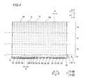
Fig. 4 is a front elevational view showing the structure of a light guide plate of the liquid crystal television set shown inFig. 2 ; -
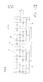
Fig. 5 is a front elevational view showing the structure of the light guide plate in the vicinity of LEDs of the liquid crystal television set shown inFig. 2 ; -
Fig. 6 is a front elevational view showing a pattern of light directing portions of the light guide plate shown inFig. 5 ; -
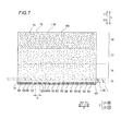
Fig. 7 is a front elevational view showing the structure of a light guide plate of a liquid crystal television set according to a second embodiment of the present invention; -
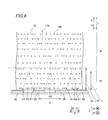
Fig. 8 is a front elevational view showing the structure of the light guide plate in the vicinity of LEDs of the liquid crystal television set shown inFig. 7 ; and -
Fig. 9 is a front elevational view showing a pattern of light directing portions of a light guide plate in a modification of the liquid crystal television set according to each of the first and second embodiments of the present invention. - First, the structure of a liquid crystal television set 300 according to a first embodiment of the present invention is described with reference to
Figs. 1 to 6 . The liquidcrystal television set 300 is an example of the "display" in the present invention. - The liquid
crystal television set 300 according to the first embodiment includes afront cabinet 10, arear cabinet 20, aliquid crystal module 30, and atuner 40, as shown inFigs. 1 and2 . Theliquid crystal module 30 includes a plurality ofLEDs 50, anLED substrate 60, alight guide plate 70, amold frame 80, and aliquid crystal cell 130. TheLEDs 50 are examples of the "light sources" or the "point light sources" in the present invention, and thetuner 40 is an example of the "receiving portion" in the present invention. Theliquid crystal cell 130 is an example of the "display cell" in the present invention. - The
front cabinet 10 is arranged on the front side (along arrow Z1) of the liquidcrystal television set 300. Thefront cabinet 10 engages with themold frame 80 of theliquid crystal module 30 from the front side (along arrow Z1) of the liquidcrystal television set 300. - The
rear cabinet 20 is arranged on the rear side (along arrow Z2) of the liquidcrystal television set 300. Therear cabinet 20 engages with themold frame 80 of theliquid crystal module 30 from the rear side (along arrow Z2) of the liquidcrystal television set 300. - The
tuner 40 is stored in a space surrounded by thefront cabinet 10 and therear cabinet 20. - The
liquid crystal module 30 is fixed by themold frame 80, and stored in a space surrounded by thefront cabinet 10 and therear cabinet 20. - The
LEDs 50 are mounted on theLED substrate 60, and theseLEDs 50 andLED substrate 60 are provided in the vicinity of a lower portion (along arrow Y2) of thelight guide plate 70. TheLEDs 50 emit light toward thelight guide plate 70. - According to the first embodiment, the
LEDs 50 are arranged in a direction X at constant arrangement intervals (pitches) D, as shown inFig. 4 . TheLEDs 50 arranged in the direction X are arranged to be parallel to aside surface 71 of thelight guide plate 70 and opposed to theside surface 71 at a short distance. According to the first embodiment, each of the arrangement intervals D is about 10 mm. - The
light guide plate 70 is in the form of a substantially rectangular flat plate, and includes theside surface 71 constituting a light-receiving surface on which the light emitted from theLEDs 50 is incident, abottom surface 72, and asurface 73 constituting a light-emitting surface, as shown inFigs. 2 and3 . Areflection sheet 90 is provided to cover thebottom surface 72 of thelight guide plate 70 and the sides of theLEDs 50 and theLED substrate 60 along arrow Y2. Thus, the light emitted from theLEDs 50 to thelight guide plate 70 and light leaking from thebottom surface 72 of thelight guide plate 70 to the rear surface (along arrow Z2) of thelight guide plate 70 can be reflected by thereflection sheet 90 to be effectively emitted from thesurface 73 of thelight guide plate 70. Adiffusion sheet 110 and alens sheet 120 are arranged sequentially along arrow Z1 on the surface (along arrow Z1) of thelight guide plate 70. - A plurality of light directing
portions 100 are provided over theoverall bottom surface 72 of thelight guide plate 70 to protrude from thebottom surface 72, as shown inFigs. 2 to 4 . Thelight directing portions 100 are formed integrally with thelight guide plate 70 by an injection molding method. The light incident on thelight guide plate 70 travels along arrow Y1 inside thelight guide plate 70 while repeating total reflection inside thelight guide plate 70. The light is emitted from thesurface 73 of thelight guide plate 70 by varying an angle of incidence with respect to thesurface 73 by thelight directing portions 100. Thelight directing portions 100 each have a circular shape, as shown inFig. 6 , as viewed from the side of the surface 73 (side along arrow Z1). Thelight directing portions 100 each have a convex shape with respect to thebottom surface 72 of thelight guide plate 70, as viewed laterally (along arrow X2). All of thelight directing portions 100 are formed in substantially the same size. In other words, all of thelight directing portions 100 are formed in substantially the same shape having regularity. Thelight directing portions 100 each have a width smaller than the width of each of theLEDs 50 in a first direction (direction X) in which theside surface 71 constituting the light-receiving surface of thelight guide plate 70 extends. According to the first embodiment, the diameter of each of thelight directing portions 100 viewed from the side of the surface 73 (side along arrow Z1) is about 0.4 mm. - Next, a pattern of the
light directing portions 100 is described. As shown inFigs. 4 to 6 , in aprescribed region 75, thelight directing portions 100 are irregularly arranged in the first direction (direction X) in which theLEDs 50 are arranged. Theprescribed region 75 is in the vicinity of theside surface 71 serving as the light-receiving surface of thelight guide plate 70, and a region from L = 0 to L = D (L denotes a distance in a direction Y). In other words, theprescribed region 75 is a region of L/D ≤ 1. On the other hand, thelight directing portions 100 inregions 76 to 78 obtained by equally dividing a region of thelight guide plate 70 located beyond the prescribedregion 75 along arrow Y1 into three parts are regularly arranged in the first direction (direction X) in which theLEDs 50 are arranged. - As shown in
Figs. 5 and6 , in the prescribed region 75 (corresponding to a region of L/D ≤ 1), the adjacentlight directing portions 100 are arranged at irregular intervals in the first direction (direction X) in which theLEDs 50 substantially parallel to theside surface 71 of thelight guide plate 70 are arranged. On the other hand, the adjacentlight directing portions 100 are arranged at substantially constant intervals in a second direction (direction Y) substantially orthogonal to the first direction. In theprescribed region 75, the light emitted from the plurality ofLEDs 50 does not sufficiently overlap, so that a difference in the amount of light between regions A1 (seeFig. 5 ) having a large amount of incident light, opposed to theLEDs 50 and regions A2 (seeFig. 5 ) having a small amount of incident light, opposed to positions between theLEDs 50 increases. Therefore, in the prescribedregion 75, relatively bright regions (regions A1 having a large amount of incident light, facing the LEDs 50) and relatively dark regions (regions A2 having a small amount of incident light, facing the positions between the LEDs 50) regularly emerge along the arrangement direction (direction X) of theLEDs 50. According to the first embodiment, thelight directing portions 100 are irregularly arranged on thebottom surface 72 of thelight guide plate 70 along the direction X, and hence light entering the regions A1 and light entering the regions A2 are dispersed in the direction X. Consequently, a difference in brightness between the regions A1 and the regions A2 is reduced. - In other words, a border between brightness and darkness of the
light guide plate 70 causing difference in brightness of theliquid crystal cell 130 and color unevenness thereof becomes blurred, whereby color unevenness of theliquid crystal cell 130 can be suppressed. Furthermore, even if positional deviation of thelight guide plate 70 and theLEDs 50 occurs, thelight directing portions 100 are irregularly arranged so that unevenness of the amount of light emitted from the light guide plate can be suppressed. - The plurality of light directing
portions 100 are so configured that arrangement intervals therebetween have regularity in theregions 76 to 78 of thelight guide plate 70. Specifically, in theregions 76 to 78 (corresponding to regions of L/D > 1), the adjacentlight directing portions 100 are arranged at constant intervals P in the first direction (direction X) in which theLEDs 50 are arranged to be substantially parallel to theside surface 71 of thelight guide plate 70. On the other hand, the adjacentlight directing portions 100 are so arranged that intervals therebetween in the second direction (direction Y) orthogonal to the first direction gradually decreases along arrow Y1. In other words, thelight directing portions 100 are so configured that the arrangement intervals therebetween decrease with distance from theLEDs 50. In these regions, the light emitted from the plurality ofLEDs 50 sufficiently overlaps, so that a difference in the amount of light between regions of the light guide plate opposed to theLEDs 50 and regions of the light guide plate opposed to the positions between theLEDs 50 is not enough to emerge as a difference in brightness of theliquid crystal cell 130. Therefore, the adjacentlight directing portions 100 are arranged at the substantially constant intervals P in the first direction (direction X). The arrangement intervals between thelight directing portions 100 each have a width smaller than the width of each of theLEDs 50 in the first direction (direction X) in which theside surface 71 constituting the light-receiving surface of thelight guide plate 70 extends. - The
light directing portions 100 are so configured on thelight guide plate 70 that the intervals between the adjacentlight directing portions 100 decrease along arrow Y1, as shown inFig. 4 . Thelight directing portions 100 are formed in substantially the same size, and hence the density of thelight directing portions 100 increases with distance from theLEDs 50. Thus, a large amount of light can be applied toward thesurface 73 even from a portion of thelight guide plate 70 having a small amount of incident light, far from theLEDs 50 by increasing the density of thelight directing portions 100. - The
diffusion sheet 110 is arranged on the surface 73 (along arrow Z1) of thelight guide plate 70, as shown inFig. 2 , and has a function of uniformly applying light to theliquid crystal cell 130. Thelens sheet 120 is arranged on a surface (along arrow Z1) of thediffusion sheet 110, and has a function of improving brightness on a display surface. - The
liquid crystal cell 130 is fixed on the side of themold frame 80 along arrow Z1, as shown inFigs. 2 and3 . Anantireflective sheet 140 is arranged on the side of a surface (along arrow Z1) of theliquid crystal cell 130. - According to the first embodiment, as hereinabove described, the plurality of light directing
portions 100 are so arranged that the arrangement intervals therebetween are irregular, whereby thelight directing portions 100 may not be arranged on thelight guide plate 70 to correspond to the arrangement of theLEDs 50. Thus, variation in the amount of light emitted from thelight guide plate 70 in a case where positional deviation of thelight guide plate 70 and theLEDs 50 occurs can be suppressed, and hence reduction in display quality can be suppressed even if the positional deviation of thelight guide plate 70 and theLEDs 50 occurs. - According to the first embodiment, as hereinabove described, the plurality of light directing
portions 100 are so arranged that the density thereof increases with distance from theLEDs 50 while the arrangement intervals therebetween are irregular. Thus, in the portion of thelight guide plate 70 having a small amount of incident light from theLEDs 50, the densely arranged light directingportions 100 can efficiently direct light to thesurface 73 of thelight guide plate 70 so that a sufficient amount of emitted light can be ensured over theentire surface 73 of thelight guide plate 70, while the irregularly arranged light directingportions 100 suppress reduction in display quality even if the positional deviation of thelight guide plate 70 and theLEDs 50 occurs. - According to the first embodiment, as hereinabove described, the plurality of light directing
portions 100 are so configured that the arrangement intervals therebetween are irregular in the prescribedregion 75 where the ratio L/D of the distance L along arrow Y1 from the light-receiving surface of thelight guide plate 70 to the distance D between theadjacent LEDs 50 is less than or equal to 1. Thus, reduction in display quality can be easily suppressed more effectively in the region of L/D ≤ 1 of thelight guide plate 70 in the vicinity of the light-receiving surface, where the effect of difference in brightness due to the amount of incident light easily appears. - According to the first embodiment, as hereinabove described, the plurality of light directing
portions 100 are so configured that the arrangement intervals therebetween and the areas thereof have regularity in theregions 76 to 78 of thelight guide plate 70, whereby thelight directing portions 100 having regularity in theregions 76 to 78 of thelight guide plate 70 can direct light uniformly to the light-emitting surface of thelight guide plate 70 while reduction in display quality is effectively suppressed in the region of thelight guide plate 70 in the vicinity of the light-receiving surface. - According to the first embodiment, as hereinabove described, the plurality of light directing
portions 100 are so arranged that the arrangement intervals therebetween decrease with distance from theLEDs 50. Thus, thelight directing portions 100 can be densely arranged in the portion of thelight guide plate 70 having a small amount of incident light from theLEDs 50, far from theLEDs 50, and hence a sufficient amount of emitted light can be ensured over the entire light-emitting surface of thelight guide plate 70. - According to the first embodiment, as hereinabove described, the plurality of light directing
portions 100 are formed in the same shape, whereby reduction in display quality can be easily suppressed simply by varying the arrangement intervals between thelight directing portions 100, even if positional deviation of thelight guide plate 70 and theLEDs 50 occurs. - According to the first embodiment, as hereinabove described, the plurality of light directing
portions 100 are so arranged that the arrangement intervals therebetween are irregular in the first direction in which theLEDs 50 are arranged, whereby the regions A1 having a large amount of incident light and the regions A2 having a small amount of incident light easily emerge along the first direction in which theLEDs 50 are arranged so that the effect of positional deviation in the first direction can be effectively suppressed. - According to the first embodiment, as hereinabove described, the plurality of light directing
portions 100 so arranged that the arrangement intervals therebetween are irregular are configured to direct the light emitted from theLEDs 50 to thesurface 73 of thelight guide plate 70. Thus, light is radially emitted so that reduction in display quality resulting from positional deviation of thelight guide plate 70 and theLEDs 50 can be suppressed by the irregularly arranged light directingportions 100, even if theLEDs 50 that are point light sources likely to form the regions A1 having a large amount of incident light and the regions A2 having a small amount of incident light in thelight guide plate 70 are employed. - According to the first embodiment, as hereinabove described, the plurality of
LEDs 50 are arranged while the plurality of light directingportions 100 each are configured to have the width smaller than the width of each of theLEDs 50 in the direction X in which the light-receiving surface of thelight guide plate 70 extends. Thus, the more numerouslight directing portions 100 can be arranged so that light can be efficiently applied to thelight directing portions 100. Consequently, reduction in display quality can be easily suppressed even if positional deviation of thelight guide plate 70 and theLEDs 50 occurs. - According to the first embodiment, as hereinabove described, the plurality of light directing
portions 100 are so configured that each of the arrangement intervals therebetween is smaller than the width of each of theLEDs 50 in the direction X in which the light-receiving surface of thelight guide plate 70 extends. Thus, the arrangement intervals between thelight directing portions 100 narrow so that light can be efficiently applied to thelight directing portions 100. Consequently, reduction in display quality can be easily suppressed even if positional deviation of thelight guide plate 70 and theLEDs 50 occurs. - The structure of a liquid crystal television set 400 (see
Fig. 1 ) according to a second embodiment of the present invention is now described with reference toFigs. 7 and8 . The liquidcrystal television set 400 is an example of the "display" in the present invention. - In this second embodiment, arrangement intervals between light directing
portions 100 inregions 76 to 78 are set to be irregular in a first direction (direction X), dissimilarly to the first embodiment in which the arrangement intervals between thelight directing portions 100 in theregions 76 to 78 are set to be regular in the first direction (direction X). - As shown in
Figs. 7 and8 , in alight guide plate 170 of the liquidcrystal television set 400 according to the second embodiment, arrangement intervals between thelight directing portions 100 in aprescribed region 75 and theregions 76 to 78 are irregular in the first direction (direction X). The arrangement of thelight directing portions 100 in the prescribedregion 75 is similar to that of thelight directing portions 100 according to the aforementioned first embodiment. - In the second embodiment, the adjacent
light directing portions 100 are arranged at irregular intervals in the first direction (direction X) also in theregions 76 to 78 similarly to the prescribedregion 75. Therefore, the arrangement intervals between thelight directing portions 100 are irregular in the first direction (direction X) over the entire region of thelight guide plate 170. - In the
regions 76 to 78, thelight directing portions 100 are so configured on thelight guide plate 170 that the intervals between the adjacentlight directing portions 100 gradually decrease along arrow Y1, as shown inFig. 7 . Thelight directing portions 100 are formed in substantially the same size, and hence the density of thelight directing portions 100 increases with distance from light sources. Thus, a large amount of light can be applied toward asurface 73 even from a portion of thelight guide plate 170 having a small amount of incident light, far from the light sources by increasing the density of thelight directing portions 100. - The remaining structure of the second embodiment is similar to that of the aforementioned first embodiment.
- According to the second embodiment, as hereinabove described, the plurality of light directing
portions 100 are so configured that the arrangement intervals therebetween are irregular over the overalllight guide plate 170. Thus, variation in the amount of light emitted from thelight guide plate 170 can be suppressed over the overalllight guide plate 170 if positional deviation of thelight guide plate 170 andLEDs 50 occurs, and hence reduction in display quality can be suppressed over the entire display region of aliquid crystal cell 130 even if the positional deviation of thelight guide plate 170 and theLEDs 50 occurs. - The remaining effects of the second embodiment are similar to those of the aforementioned first embodiment.
- Although the present invention has been described and illustrated in detail, it is clearly understood that the same is by way of illustration and example only and is not to be taken by way of limitation, the spirit and scope of the present invention being limited only by the terms of the appended claims.
- While the present invention is applied to the liquid crystal television set in each of the aforementioned first and second embodiments, the present invention is not restricted to this. The present invention may alternatively be applied to a liquid crystal display, a display, and a television set other than the liquid crystal television set.
- While the arrangement intervals between the plurality of light directing
portions 100 provided on the light guide plate are irregular in each of the aforementioned first and second embodiments, the present invention is not restricted to this. As in a modification shown inFig. 9 , a plurality of light directingportions 200 may alternatively be so arranged that the areas thereof are irregular. Furthermore, both the arrangement intervals between the plurality of light directing portions and the areas thereof may alternatively be irregular. - While the plurality of light directing portions are so configured that the arrangement intervals therebetween are irregular in the prescribed
region 75 where the ratio L/D of the distance L to the distance D is less than or equal to 1 in the aforementioned first embodiment, and the plurality of light directing portions are so configured that the arrangement intervals therebetween are irregular in all theprescribed region 75 andregions 76 to 78 of L/D > 1 in the aforementioned second embodiment, the present invention is not restricted to this. The plurality of light directing portions may alternatively be so configured that the arrangement intervals therebetween are irregular in the regions satisfying L/D > 1. - While the arrangement intervals between the light directing portions are irregular in the first direction (direction X) in which the LEDs are arranged in each of the aforementioned first and second embodiments, the present invention is not restricted to this. The arrangement intervals between the light directing portions may alternatively be irregular in the second direction (direction Y) orthogonal to the first direction. Furthermore, the arrangement intervals between the light directing portions may alternatively be irregular in both the first direction (direction X) in which the light sources are arranged and the second direction (direction Y) orthogonal to the first direction.
- While the density of the light directing portions increases with distance from the LEDs in each of the aforementioned first and second embodiments, the present invention is not restricted to this. The density of the light directing portions may alternatively be constant regardless of a distance from the LEDs.
- While each of the light directing portions is in the circular shape in each of the aforementioned first and second embodiments, the present invention is not restricted to this. As in the modification shown in
Fig. 9 , the light directing portions may alternatively include first light directing portions each having a substantially circular shape and second light directing portions each having a substantially flattened shape. Furthermore, each of the light directing portions may alternatively be in a rectangular shape, a triangular shape, an elliptical shape, etc. According to this structure, the areas of the light directing portions can be easily irregularized simply by combining the substantially circular shape and the substantially flattened shape. - While each of the light directing portions protrudes in the convex shape from the bottom surface of the light guide plate, as viewed from the side of the side surface of the light guide plate in each of the aforementioned first and second embodiments, the present invention is not restricted to this. The light directing portions may alternatively be concaved with respect to the bottom surface of the light guide plate, as viewed from the side of the side surface of the light guide plate. For example, each of the light directing portions may alternatively be concaved in a rectangular shape or a triangular shape.
- While the LEDs are arranged in the direction X at the constant arrangement intervals (pitches) D in each of the aforementioned first and second embodiments, the present invention is not restricted to this. The arrangement intervals (pitches) between the light sources may not be constant.
- While the light directing portions are integrally formed on the bottom surface of the light guide plate by the injection molding method in each of the aforementioned first and second embodiments, the present invention is not restricted to this. The light directing portions may alternatively be arranged on the light guide plate by screen printing or the like.
- While the LEDs are provided in the vicinity of the lower portion (along arrow Y2) of the light guide plate in each of the aforementioned first and second embodiments, the present invention is not restricted to this. The light sources may alternatively be provided on the upper surface side (side of a side surface 74) of the light guide plate or the side of a side surface of the light guide plate in a short-side direction.
- While the LEDs are provided as the light sources in each of the aforementioned first and second embodiments, the present invention is not restricted to this. A halogen lamp or a metal hydro lamp may alternatively be provided as a light source.
- While both the areas of the light directing portions and the arrangement intervals therebetween have regularity in the
regions 76 to 78 of the light guide plate in the aforementioned first embodiment, the present invention is not restricted to this. Either the areas of the light directing portions or the arrangement intervals therebetween may alternatively have regularity.
Claims (15)
- A display (300, 400) comprising:a light source (50);a light guide plate (70) having a side surface (71) constituting a light-receiving surface on which light emitted from said light source is incident, a bottom surface (72), and a surface (73) constituting a light-emitting surface;a plurality of light directing portions (100) provided on said bottom surface of said light guide plate, directing said light incident on said light guide plate to said light-emitting surface; anda display cell (130) arranged on said light-emitting surface of said light guide plate, whereinsaid plurality of light directing portions provided on said bottom surface of said light guide plate are so arranged that at least either arrangement intervals between said plurality of light directing portions or areas of said plurality of light directing portions are irregular.
- The display according to claim 1, wherein
said plurality of light directing portions are so arranged that density of said plurality of light directing portions increases with distance from said light source while at least either arrangement intervals between said plurality of light directing portions or areas of said plurality of light directing portions are irregular. - The display according to claim 1, wherein
said plurality of light directing portions are so configured that at least either arrangement intervals between said plurality of light directing portions or areas of said plurality of light directing portions are irregular in at least a prescribed region (75) of said light guide plate in a vicinity of said light-receiving surface. - The display according to claim 3, wherein
a plurality of light sources are provided to be spaced from each other by a distance D along a direction in which said light-receiving surface extends, and said prescribed region comprises a region where a ratio L/D of a distance L in a direction toward a side surface opposite to said light-receiving surface from said light-receiving surface of said light guide plate to said distance D between adjacent said light sources is less than or equal to 1. - The display according to claim 3, wherein
said plurality of light directing portions are so configured that at least either arrangement intervals between said plurality of light directing portions or areas of said plurality of light directing portions are irregular over an entire region of said light guide plate including not only said prescribed region in the vicinity of said light-receiving surface but also a region (76, 77, 78) other than said prescribed region. - The display according to claim 3, wherein
said plurality of light directing portions are so configured that at least either arrangement intervals between said plurality of light directing portions or areas of said plurality of light directing portions have regularity in a region of said light guide plate other than said prescribed region. - The display according to claim 6, wherein
said plurality of light directing portions are so arranged that arrangement intervals between said plurality of light directing portions decrease with distance from said light source. - The display according to claim 1, wherein
a plurality of light sources are provided to be spaced from each other along a first direction in which said light-receiving surface of said light guide plate extends, and
said arrangement intervals between said plurality of light directing portions are irregular in at least either said first direction or a second direction orthogonal to said first direction. - The display according to claim 7, wherein
said plurality of light directing portions have the same shape as each other. - The display according to claim 7, wherein
said arrangement intervals between said plurality of light directing portions are irregular in a first direction. - The display according to claim 1, wherein
said plurality of light directing portions are so configured that areas of said plurality of light directing portions are irregular. - The display according to claim 11, wherein
said plurality of light directing portions include a first light directing portion having a circular shape and a second light directing portion having a flattened shape. - The display according to claim 1, wherein
said light source is constituted by a point light source (50), and
light emitted from said point light source is directed to said light-emitting surface by said plurality of light directing portions so arranged that at least either arrangement intervals between said plurality of light directing portions or areas of said plurality of light directing portions are irregular. - The display according to claim 1, wherein
a plurality of light sources are arranged, and
each of said plurality of light directing portions has a width smaller than a width of each of said plurality of light sources in a first direction in which said light-receiving surface of said light guide plate extends. - The display according to claim 6, wherein
each of said arrangement intervals between said plurality of light directing portions is smaller than a width of said light source in a first direction in which said light-receiving surface of said light guide plate extends.
Applications Claiming Priority (1)
| Application Number | Priority Date | Filing Date | Title |
|---|---|---|---|
| JP2011107358A JP2012237897A (en) | 2011-05-12 | 2011-05-12 | Liquid crystal display device, and liquid crystal television device |
Publications (2)
| Publication Number | Publication Date |
|---|---|
| EP2523040A1 true EP2523040A1 (en) | 2012-11-14 |
| EP2523040B1 EP2523040B1 (en) | 2015-08-26 |
Family
ID=46148616
Family Applications (1)
| Application Number | Title | Priority Date | Filing Date |
|---|---|---|---|
| EP12166500.4A Not-in-force EP2523040B1 (en) | 2011-05-12 | 2012-05-03 | Display with a light guide plate |
Country Status (3)
| Country | Link |
|---|---|
| US (1) | US20120287346A1 (en) |
| EP (1) | EP2523040B1 (en) |
| JP (1) | JP2012237897A (en) |
Cited By (1)
| Publication number | Priority date | Publication date | Assignee | Title |
|---|---|---|---|---|
| EP3040605A1 (en) * | 2015-01-02 | 2016-07-06 | Goodrich Lighting Systems GmbH | Light unit with an extended light emission surface |
Families Citing this family (1)
| Publication number | Priority date | Publication date | Assignee | Title |
|---|---|---|---|---|
| USD1041433S1 (en) * | 2022-03-02 | 2024-09-10 | Samsung Electronics Co., Ltd. | Portable television set |
Citations (3)
| Publication number | Priority date | Publication date | Assignee | Title |
|---|---|---|---|---|
| US20020054488A1 (en) * | 2000-08-11 | 2002-05-09 | Enplas Corporation | Light guide plate, surface light source device and display |
| US20020197051A1 (en) * | 2001-05-22 | 2002-12-26 | Yuuki Tamura | Optical waveguide plate of surface light emitting apparatus |
| JP2007012323A (en) | 2005-06-28 | 2007-01-18 | Cheil Ind Co Ltd | Surface light source device, and liquid crystal display device |
Family Cites Families (7)
| Publication number | Priority date | Publication date | Assignee | Title |
|---|---|---|---|---|
| US7525531B2 (en) * | 2000-07-31 | 2009-04-28 | Toshiba Matsushita Display Technology Co., Ltd. | Method for manufacturing lighting device, image display, liquid crystal monitor, liquid crystal television, liquid crystal information terminal, and light guide plate |
| JP3896895B2 (en) * | 2001-05-22 | 2007-03-22 | 日亜化学工業株式会社 | Light guide plate for surface light emitting device |
| CN101142443A (en) * | 2005-03-18 | 2008-03-12 | 富士通株式会社 | Light guide plate, light source and display panel unit and electronic device |
| JP4307477B2 (en) * | 2006-07-04 | 2009-08-05 | 三星モバイルディスプレイ株式會社 | Light guide plate and backlight unit |
| JP2008218077A (en) * | 2007-03-01 | 2008-09-18 | Citizen Finetech Miyota Co Ltd | Surface-emitting device |
| KR101351864B1 (en) * | 2007-05-08 | 2014-01-15 | 삼성디스플레이 주식회사 | Light guide plate, back light assembly and display device having the same |
| US8248560B2 (en) * | 2008-04-18 | 2012-08-21 | Pixtronix, Inc. | Light guides and backlight systems incorporating prismatic structures and light redirectors |
-
2011
- 2011-05-12 JP JP2011107358A patent/JP2012237897A/en active Pending
-
2012
- 2012-05-02 US US13/462,434 patent/US20120287346A1/en not_active Abandoned
- 2012-05-03 EP EP12166500.4A patent/EP2523040B1/en not_active Not-in-force
Patent Citations (3)
| Publication number | Priority date | Publication date | Assignee | Title |
|---|---|---|---|---|
| US20020054488A1 (en) * | 2000-08-11 | 2002-05-09 | Enplas Corporation | Light guide plate, surface light source device and display |
| US20020197051A1 (en) * | 2001-05-22 | 2002-12-26 | Yuuki Tamura | Optical waveguide plate of surface light emitting apparatus |
| JP2007012323A (en) | 2005-06-28 | 2007-01-18 | Cheil Ind Co Ltd | Surface light source device, and liquid crystal display device |
Cited By (3)
| Publication number | Priority date | Publication date | Assignee | Title |
|---|---|---|---|---|
| EP3040605A1 (en) * | 2015-01-02 | 2016-07-06 | Goodrich Lighting Systems GmbH | Light unit with an extended light emission surface |
| CN105759338A (en) * | 2015-01-02 | 2016-07-13 | 古德里奇照明系统有限责任公司 | Light unit with an extended light emission surface |
| US10371879B2 (en) | 2015-01-02 | 2019-08-06 | Goodrich Lighting Systems Gmbh | Light unit with an extended light emission surface |
Also Published As
| Publication number | Publication date |
|---|---|
| US20120287346A1 (en) | 2012-11-15 |
| JP2012237897A (en) | 2012-12-06 |
| EP2523040B1 (en) | 2015-08-26 |
Similar Documents
| Publication | Publication Date | Title |
|---|---|---|
| US8979292B2 (en) | Display, television set, and liquid crystal television set | |
| JP5021070B2 (en) | LIGHT EMITTING ELEMENT, LIGHTING DEVICE, AND LIQUID CRYSTAL DISPLAY DEVICE | |
| EP2811336B1 (en) | Illuminating apparatus and liquid crystal display having the same | |
| EP2463706B1 (en) | Back light unit and display apparatus using the same | |
| US8277104B2 (en) | LED back-light unit and display device | |
| US8525946B2 (en) | Liquid crystal display apparatus having different size and amount of patterns formed on different areas of bottom surface of a light guide panel of a backlight unit | |
| EP2515027A1 (en) | Illumination device, display device, and television receiver | |
| KR20160022220A (en) | Light guide plate, backlight unit and display device having the same | |
| US8794780B2 (en) | Lighting device with light-scattering optical member | |
| EP2738452B1 (en) | Backlight unit, liquid crystal display device having the same and fabrication method thereof | |
| EP3200019B1 (en) | Backlight module and display device | |
| KR20190063904A (en) | Backlight unit and display device | |
| US7540630B2 (en) | Backlight module and scattering module for same | |
| EP2133738A1 (en) | Optical member unit, lighting device for display, display, and television receiver | |
| US20140313772A1 (en) | Illumination device, and display device provided therewith | |
| EP2461091B1 (en) | Backlight unit and image display using the same | |
| EP2523040B1 (en) | Display with a light guide plate | |
| JP2010277851A (en) | LIGHTING DEVICE AND DISPLAY DEVICE USING THE SAME | |
| KR102425442B1 (en) | Display and device | |
| EP3605214B1 (en) | Display device | |
| KR101429486B1 (en) | Light Guiding Plate and Backlight unit | |
| US10338292B2 (en) | Light guide plate, backlight module and display device | |
| US20140177198A1 (en) | Light source module and keyboard having the same | |
| US20160245977A1 (en) | Reflective film, backlight module and display apparatus | |
| KR102582503B1 (en) | Liquid crystal display device |
Legal Events
| Date | Code | Title | Description |
|---|---|---|---|
| PUAI | Public reference made under article 153(3) epc to a published international application that has entered the european phase |
Free format text: ORIGINAL CODE: 0009012 |
|
| AK | Designated contracting states |
Kind code of ref document: A1 Designated state(s): AL AT BE BG CH CY CZ DE DK EE ES FI FR GB GR HR HU IE IS IT LI LT LU LV MC MK MT NL NO PL PT RO RS SE SI SK SM TR |
|
| AX | Request for extension of the european patent |
Extension state: BA ME |
|
| 17P | Request for examination filed |
Effective date: 20130510 |
|
| 17Q | First examination report despatched |
Effective date: 20130613 |
|
| GRAP | Despatch of communication of intention to grant a patent |
Free format text: ORIGINAL CODE: EPIDOSNIGR1 |
|
| INTG | Intention to grant announced |
Effective date: 20150304 |
|
| RIN1 | Information on inventor provided before grant (corrected) |
Inventor name: TOMOHISA, TAJIRI |
|
| GRAS | Grant fee paid |
Free format text: ORIGINAL CODE: EPIDOSNIGR3 |
|
| GRAA | (expected) grant |
Free format text: ORIGINAL CODE: 0009210 |
|
| AK | Designated contracting states |
Kind code of ref document: B1 Designated state(s): AL AT BE BG CH CY CZ DE DK EE ES FI FR GB GR HR HU IE IS IT LI LT LU LV MC MK MT NL NO PL PT RO RS SE SI SK SM TR |
|
| REG | Reference to a national code |
Ref country code: GB Ref legal event code: FG4D |
|
| REG | Reference to a national code |
Ref country code: CH Ref legal event code: EP |
|
| REG | Reference to a national code |
Ref country code: AT Ref legal event code: REF Ref document number: 745528 Country of ref document: AT Kind code of ref document: T Effective date: 20150915 |
|
| REG | Reference to a national code |
Ref country code: IE Ref legal event code: FG4D |
|
| REG | Reference to a national code |
Ref country code: DE Ref legal event code: R096 Ref document number: 602012009930 Country of ref document: DE |
|
| REG | Reference to a national code |
Ref country code: AT Ref legal event code: MK05 Ref document number: 745528 Country of ref document: AT Kind code of ref document: T Effective date: 20150826 |
|
| REG | Reference to a national code |
Ref country code: LT Ref legal event code: MG4D |
|
| PG25 | Lapsed in a contracting state [announced via postgrant information from national office to epo] |
Ref country code: GR Free format text: LAPSE BECAUSE OF FAILURE TO SUBMIT A TRANSLATION OF THE DESCRIPTION OR TO PAY THE FEE WITHIN THE PRESCRIBED TIME-LIMIT Effective date: 20151127 Ref country code: LT Free format text: LAPSE BECAUSE OF FAILURE TO SUBMIT A TRANSLATION OF THE DESCRIPTION OR TO PAY THE FEE WITHIN THE PRESCRIBED TIME-LIMIT Effective date: 20150826 Ref country code: NO Free format text: LAPSE BECAUSE OF FAILURE TO SUBMIT A TRANSLATION OF THE DESCRIPTION OR TO PAY THE FEE WITHIN THE PRESCRIBED TIME-LIMIT Effective date: 20151126 Ref country code: LV Free format text: LAPSE BECAUSE OF FAILURE TO SUBMIT A TRANSLATION OF THE DESCRIPTION OR TO PAY THE FEE WITHIN THE PRESCRIBED TIME-LIMIT Effective date: 20150826 Ref country code: FI Free format text: LAPSE BECAUSE OF FAILURE TO SUBMIT A TRANSLATION OF THE DESCRIPTION OR TO PAY THE FEE WITHIN THE PRESCRIBED TIME-LIMIT Effective date: 20150826 |
|
| REG | Reference to a national code |
Ref country code: NL Ref legal event code: MP Effective date: 20150826 |
|
| PG25 | Lapsed in a contracting state [announced via postgrant information from national office to epo] |
Ref country code: IS Free format text: LAPSE BECAUSE OF FAILURE TO SUBMIT A TRANSLATION OF THE DESCRIPTION OR TO PAY THE FEE WITHIN THE PRESCRIBED TIME-LIMIT Effective date: 20151226 Ref country code: RS Free format text: LAPSE BECAUSE OF FAILURE TO SUBMIT A TRANSLATION OF THE DESCRIPTION OR TO PAY THE FEE WITHIN THE PRESCRIBED TIME-LIMIT Effective date: 20150826 Ref country code: HR Free format text: LAPSE BECAUSE OF FAILURE TO SUBMIT A TRANSLATION OF THE DESCRIPTION OR TO PAY THE FEE WITHIN THE PRESCRIBED TIME-LIMIT Effective date: 20150826 Ref country code: AT Free format text: LAPSE BECAUSE OF FAILURE TO SUBMIT A TRANSLATION OF THE DESCRIPTION OR TO PAY THE FEE WITHIN THE PRESCRIBED TIME-LIMIT Effective date: 20150826 Ref country code: SE Free format text: LAPSE BECAUSE OF FAILURE TO SUBMIT A TRANSLATION OF THE DESCRIPTION OR TO PAY THE FEE WITHIN THE PRESCRIBED TIME-LIMIT Effective date: 20150826 Ref country code: PL Free format text: LAPSE BECAUSE OF FAILURE TO SUBMIT A TRANSLATION OF THE DESCRIPTION OR TO PAY THE FEE WITHIN THE PRESCRIBED TIME-LIMIT Effective date: 20150826 Ref country code: ES Free format text: LAPSE BECAUSE OF FAILURE TO SUBMIT A TRANSLATION OF THE DESCRIPTION OR TO PAY THE FEE WITHIN THE PRESCRIBED TIME-LIMIT Effective date: 20150826 Ref country code: PT Free format text: LAPSE BECAUSE OF FAILURE TO SUBMIT A TRANSLATION OF THE DESCRIPTION OR TO PAY THE FEE WITHIN THE PRESCRIBED TIME-LIMIT Effective date: 20151228 |
|
| PG25 | Lapsed in a contracting state [announced via postgrant information from national office to epo] |
Ref country code: NL Free format text: LAPSE BECAUSE OF FAILURE TO SUBMIT A TRANSLATION OF THE DESCRIPTION OR TO PAY THE FEE WITHIN THE PRESCRIBED TIME-LIMIT Effective date: 20150826 |
|
| REG | Reference to a national code |
Ref country code: FR Ref legal event code: PLFP Year of fee payment: 5 |
|
| PG25 | Lapsed in a contracting state [announced via postgrant information from national office to epo] |
Ref country code: CZ Free format text: LAPSE BECAUSE OF FAILURE TO SUBMIT A TRANSLATION OF THE DESCRIPTION OR TO PAY THE FEE WITHIN THE PRESCRIBED TIME-LIMIT Effective date: 20150826 Ref country code: DK Free format text: LAPSE BECAUSE OF FAILURE TO SUBMIT A TRANSLATION OF THE DESCRIPTION OR TO PAY THE FEE WITHIN THE PRESCRIBED TIME-LIMIT Effective date: 20150826 Ref country code: EE Free format text: LAPSE BECAUSE OF FAILURE TO SUBMIT A TRANSLATION OF THE DESCRIPTION OR TO PAY THE FEE WITHIN THE PRESCRIBED TIME-LIMIT Effective date: 20150826 Ref country code: SK Free format text: LAPSE BECAUSE OF FAILURE TO SUBMIT A TRANSLATION OF THE DESCRIPTION OR TO PAY THE FEE WITHIN THE PRESCRIBED TIME-LIMIT Effective date: 20150826 Ref country code: IT Free format text: LAPSE BECAUSE OF FAILURE TO SUBMIT A TRANSLATION OF THE DESCRIPTION OR TO PAY THE FEE WITHIN THE PRESCRIBED TIME-LIMIT Effective date: 20150826 |
|
| REG | Reference to a national code |
Ref country code: DE Ref legal event code: R097 Ref document number: 602012009930 Country of ref document: DE |
|
| PG25 | Lapsed in a contracting state [announced via postgrant information from national office to epo] |
Ref country code: RO Free format text: LAPSE BECAUSE OF FAILURE TO SUBMIT A TRANSLATION OF THE DESCRIPTION OR TO PAY THE FEE WITHIN THE PRESCRIBED TIME-LIMIT Effective date: 20150826 |
|
| PLBE | No opposition filed within time limit |
Free format text: ORIGINAL CODE: 0009261 |
|
| STAA | Information on the status of an ep patent application or granted ep patent |
Free format text: STATUS: NO OPPOSITION FILED WITHIN TIME LIMIT |
|
| PGFP | Annual fee paid to national office [announced via postgrant information from national office to epo] |
Ref country code: GB Payment date: 20160427 Year of fee payment: 5 Ref country code: DE Payment date: 20160426 Year of fee payment: 5 |
|
| 26N | No opposition filed |
Effective date: 20160530 |
|
| PG25 | Lapsed in a contracting state [announced via postgrant information from national office to epo] |
Ref country code: BE Free format text: LAPSE BECAUSE OF NON-PAYMENT OF DUE FEES Effective date: 20160531 Ref country code: SI Free format text: LAPSE BECAUSE OF FAILURE TO SUBMIT A TRANSLATION OF THE DESCRIPTION OR TO PAY THE FEE WITHIN THE PRESCRIBED TIME-LIMIT Effective date: 20150826 |
|
| PGFP | Annual fee paid to national office [announced via postgrant information from national office to epo] |
Ref country code: FR Payment date: 20160412 Year of fee payment: 5 |
|
| PG25 | Lapsed in a contracting state [announced via postgrant information from national office to epo] |
Ref country code: LU Free format text: LAPSE BECAUSE OF FAILURE TO SUBMIT A TRANSLATION OF THE DESCRIPTION OR TO PAY THE FEE WITHIN THE PRESCRIBED TIME-LIMIT Effective date: 20160503 Ref country code: BE Free format text: LAPSE BECAUSE OF FAILURE TO SUBMIT A TRANSLATION OF THE DESCRIPTION OR TO PAY THE FEE WITHIN THE PRESCRIBED TIME-LIMIT Effective date: 20150826 |
|
| REG | Reference to a national code |
Ref country code: CH Ref legal event code: PL |
|
| PG25 | Lapsed in a contracting state [announced via postgrant information from national office to epo] |
Ref country code: LI Free format text: LAPSE BECAUSE OF NON-PAYMENT OF DUE FEES Effective date: 20160531 Ref country code: CH Free format text: LAPSE BECAUSE OF NON-PAYMENT OF DUE FEES Effective date: 20160531 |
|
| REG | Reference to a national code |
Ref country code: IE Ref legal event code: MM4A |
|
| PG25 | Lapsed in a contracting state [announced via postgrant information from national office to epo] |
Ref country code: IE Free format text: LAPSE BECAUSE OF NON-PAYMENT OF DUE FEES Effective date: 20160503 |
|
| REG | Reference to a national code |
Ref country code: DE Ref legal event code: R119 Ref document number: 602012009930 Country of ref document: DE |
|
| GBPC | Gb: european patent ceased through non-payment of renewal fee |
Effective date: 20170503 |
|
| REG | Reference to a national code |
Ref country code: FR Ref legal event code: ST Effective date: 20180131 |
|
| PG25 | Lapsed in a contracting state [announced via postgrant information from national office to epo] |
Ref country code: DE Free format text: LAPSE BECAUSE OF NON-PAYMENT OF DUE FEES Effective date: 20171201 Ref country code: GB Free format text: LAPSE BECAUSE OF NON-PAYMENT OF DUE FEES Effective date: 20170503 |
|
| PG25 | Lapsed in a contracting state [announced via postgrant information from national office to epo] |
Ref country code: SM Free format text: LAPSE BECAUSE OF FAILURE TO SUBMIT A TRANSLATION OF THE DESCRIPTION OR TO PAY THE FEE WITHIN THE PRESCRIBED TIME-LIMIT Effective date: 20150826 Ref country code: FR Free format text: LAPSE BECAUSE OF NON-PAYMENT OF DUE FEES Effective date: 20170531 Ref country code: CY Free format text: LAPSE BECAUSE OF FAILURE TO SUBMIT A TRANSLATION OF THE DESCRIPTION OR TO PAY THE FEE WITHIN THE PRESCRIBED TIME-LIMIT Effective date: 20150826 Ref country code: HU Free format text: LAPSE BECAUSE OF FAILURE TO SUBMIT A TRANSLATION OF THE DESCRIPTION OR TO PAY THE FEE WITHIN THE PRESCRIBED TIME-LIMIT; INVALID AB INITIO Effective date: 20120503 |
|
| PG25 | Lapsed in a contracting state [announced via postgrant information from national office to epo] |
Ref country code: MC Free format text: LAPSE BECAUSE OF FAILURE TO SUBMIT A TRANSLATION OF THE DESCRIPTION OR TO PAY THE FEE WITHIN THE PRESCRIBED TIME-LIMIT Effective date: 20150826 Ref country code: MT Free format text: LAPSE BECAUSE OF NON-PAYMENT OF DUE FEES Effective date: 20160531 Ref country code: TR Free format text: LAPSE BECAUSE OF FAILURE TO SUBMIT A TRANSLATION OF THE DESCRIPTION OR TO PAY THE FEE WITHIN THE PRESCRIBED TIME-LIMIT Effective date: 20150826 Ref country code: MK Free format text: LAPSE BECAUSE OF FAILURE TO SUBMIT A TRANSLATION OF THE DESCRIPTION OR TO PAY THE FEE WITHIN THE PRESCRIBED TIME-LIMIT Effective date: 20150826 |
|
| PG25 | Lapsed in a contracting state [announced via postgrant information from national office to epo] |
Ref country code: BG Free format text: LAPSE BECAUSE OF FAILURE TO SUBMIT A TRANSLATION OF THE DESCRIPTION OR TO PAY THE FEE WITHIN THE PRESCRIBED TIME-LIMIT Effective date: 20150826 |
|
| PG25 | Lapsed in a contracting state [announced via postgrant information from national office to epo] |
Ref country code: AL Free format text: LAPSE BECAUSE OF FAILURE TO SUBMIT A TRANSLATION OF THE DESCRIPTION OR TO PAY THE FEE WITHIN THE PRESCRIBED TIME-LIMIT Effective date: 20150826 |