EP2523034A1 - Oscillation mirror element - Google Patents
Oscillation mirror element Download PDFInfo
- Publication number
- EP2523034A1 EP2523034A1 EP10842214A EP10842214A EP2523034A1 EP 2523034 A1 EP2523034 A1 EP 2523034A1 EP 10842214 A EP10842214 A EP 10842214A EP 10842214 A EP10842214 A EP 10842214A EP 2523034 A1 EP2523034 A1 EP 2523034A1
- Authority
- EP
- European Patent Office
- Prior art keywords
- driving
- mirror
- driving portion
- support portion
- portions
- Prior art date
- Legal status (The legal status is an assumption and is not a legal conclusion. Google has not performed a legal analysis and makes no representation as to the accuracy of the status listed.)
- Withdrawn
Links
- 230000010355 oscillation Effects 0.000 title 1
- 238000005452 bending Methods 0.000 claims description 4
- 230000003287 optical effect Effects 0.000 description 97
- 239000000758 substrate Substances 0.000 description 21
- VYPSYNLAJGMNEJ-UHFFFAOYSA-N Silicium dioxide Chemical compound O=[Si]=O VYPSYNLAJGMNEJ-UHFFFAOYSA-N 0.000 description 10
- 230000004048 modification Effects 0.000 description 9
- 238000012986 modification Methods 0.000 description 9
- 238000006073 displacement reaction Methods 0.000 description 6
- 238000001020 plasma etching Methods 0.000 description 6
- 229910052681 coesite Inorganic materials 0.000 description 5
- 229910052906 cristobalite Inorganic materials 0.000 description 5
- 229910052451 lead zirconate titanate Inorganic materials 0.000 description 5
- 238000004519 manufacturing process Methods 0.000 description 5
- 239000000377 silicon dioxide Substances 0.000 description 5
- 229910052682 stishovite Inorganic materials 0.000 description 5
- 229910052905 tridymite Inorganic materials 0.000 description 5
- 239000000463 material Substances 0.000 description 3
- 229910052719 titanium Inorganic materials 0.000 description 3
- 239000010936 titanium Substances 0.000 description 3
- RTAQQCXQSZGOHL-UHFFFAOYSA-N Titanium Chemical compound [Ti] RTAQQCXQSZGOHL-UHFFFAOYSA-N 0.000 description 2
- 229910052782 aluminium Inorganic materials 0.000 description 2
- 229910052804 chromium Inorganic materials 0.000 description 2
- 229910052802 copper Inorganic materials 0.000 description 2
- 229920001971 elastomer Polymers 0.000 description 2
- 239000000806 elastomer Substances 0.000 description 2
- 229910052737 gold Inorganic materials 0.000 description 2
- HFGPZNIAWCZYJU-UHFFFAOYSA-N lead zirconate titanate Chemical compound [O-2].[O-2].[O-2].[O-2].[O-2].[Ti+4].[Zr+4].[Pb+2] HFGPZNIAWCZYJU-UHFFFAOYSA-N 0.000 description 2
- 238000000206 photolithography Methods 0.000 description 2
- 229910052697 platinum Inorganic materials 0.000 description 2
- 238000007740 vapor deposition Methods 0.000 description 2
- 238000001039 wet etching Methods 0.000 description 2
- 229910003334 KNbO3 Inorganic materials 0.000 description 1
- XLOMVQKBTHCTTD-UHFFFAOYSA-N Zinc monoxide Chemical compound [Zn]=O XLOMVQKBTHCTTD-UHFFFAOYSA-N 0.000 description 1
- QCWXUUIWCKQGHC-UHFFFAOYSA-N Zirconium Chemical compound [Zr] QCWXUUIWCKQGHC-UHFFFAOYSA-N 0.000 description 1
- 230000000694 effects Effects 0.000 description 1
- 230000002401 inhibitory effect Effects 0.000 description 1
- 229910052746 lanthanum Inorganic materials 0.000 description 1
- 239000007769 metal material Substances 0.000 description 1
- UKDIAJWKFXFVFG-UHFFFAOYSA-N potassium;oxido(dioxo)niobium Chemical compound [K+].[O-][Nb](=O)=O UKDIAJWKFXFVFG-UHFFFAOYSA-N 0.000 description 1
- UYLYBEXRJGPQSH-UHFFFAOYSA-N sodium;oxido(dioxo)niobium Chemical compound [Na+].[O-][Nb](=O)=O UYLYBEXRJGPQSH-UHFFFAOYSA-N 0.000 description 1
- 238000004544 sputter deposition Methods 0.000 description 1
- 229910052726 zirconium Inorganic materials 0.000 description 1
Images




Classifications
-
- G—PHYSICS
- G02—OPTICS
- G02B—OPTICAL ELEMENTS, SYSTEMS OR APPARATUS
- G02B26/00—Optical devices or arrangements for the control of light using movable or deformable optical elements
- G02B26/08—Optical devices or arrangements for the control of light using movable or deformable optical elements for controlling the direction of light
- G02B26/10—Scanning systems
-
- G—PHYSICS
- G02—OPTICS
- G02B—OPTICAL ELEMENTS, SYSTEMS OR APPARATUS
- G02B26/00—Optical devices or arrangements for the control of light using movable or deformable optical elements
- G02B26/08—Optical devices or arrangements for the control of light using movable or deformable optical elements for controlling the direction of light
- G02B26/0816—Optical devices or arrangements for the control of light using movable or deformable optical elements for controlling the direction of light by means of one or more reflecting elements
- G02B26/0833—Optical devices or arrangements for the control of light using movable or deformable optical elements for controlling the direction of light by means of one or more reflecting elements the reflecting element being a micromechanical device, e.g. a MEMS mirror, DMD
- G02B26/0841—Optical devices or arrangements for the control of light using movable or deformable optical elements for controlling the direction of light by means of one or more reflecting elements the reflecting element being a micromechanical device, e.g. a MEMS mirror, DMD the reflecting element being moved or deformed by electrostatic means
-
- B—PERFORMING OPERATIONS; TRANSPORTING
- B81—MICROSTRUCTURAL TECHNOLOGY
- B81B—MICROSTRUCTURAL DEVICES OR SYSTEMS, e.g. MICROMECHANICAL DEVICES
- B81B3/00—Devices comprising flexible or deformable elements, e.g. comprising elastic tongues or membranes
Definitions
- the present invention relates to a vibrating mirror element, and more particularly, it relates to a vibrating mirror element including a driving portion.
- a vibrating mirror element including a driving portion is known.
- Such a vibrating mirror element is disclosed in Japanese Patent Laying-Open Nos. 2009-169290 and 2007-188073 , for example.
- an optical deflector including a pair of driving portions arranged along a direction X, a mirror portion arranged to be held between this pair of driving portions in the direction X and rotated by the pair of driving portions, and a support portion arranged to surround the pair of driving portions and the mirror portion along the direction X and a direction Y (direction orthogonal to the direction X in the same plane).
- First end portions of this pair of driving portions are connected with the mirror portion on a first side of the direction X and a second side thereof, respectively.
- Second end portions of the pair of driving portions are fixed by the support portion located on sides opposite to the mirror portion in the direction X.
- the pair of driving portions are arranged such that a plurality of piezoelectric actuators extending in the direction Y are arranged in the direction X, and the plurality of piezoelectric actuators are continuously connected in a state where end portions of the plurality of piezoelectric actuators are bent.
- the first end portions of the pair of driving portions of this optical deflector are connected with the mirror portion on corners of the mirror portion on a first side of the direction Y while the second end portions of the pair of driving portions are connected with the support portion on corners of the support portion on the first side of the direction Y.
- a two-axis micro scanner including a horizontal driving portion, a pair of first cantilevers arranged on a first side of the horizontal driving portion in a direction X and extending in the direction X, a pair of second cantilevers arranged on a second side of the horizontal driving portion in the direction X and extending in the direction X, a pair of first connectors connecting each of the pair of first cantilevers and the horizontal driving portion, a pair of second connectors connecting each of the pair of second cantilevers and the horizontal driving portion, and a frame arranged to surround the aforementioned all components along the direction X and a direction Y.
- the pair of first cantilevers and the pair of second cantilevers of this two-axis micro scanner are fixed to the frame on sides opposite to the first connectors and the second connectors, respectively, in the direction X.
- One of the pair of first cantilevers and one of the pair of second cantilevers are arranged on a first straight line extending in the direction X while the other of the pair of first cantilevers and the other of the pair of second cantilevers are arranged on a second straight line extending in the direction X.
- the first end portions and the second end portions of the pair of driving portions are connected with the mirror portion and the support portion in positions (the corners of the mirror portion and the corners of the support portion) deviating to the first side of the direction Y with respect to the center of the mirror portion, and hence there is such a problem that the mirror portion is so inclined that a second side of the mirror portion in the direction X is located below a first side of the mirror portion in the direction X due to the own weight of the mirror portion in a state where the pair of driving portions are not driven (non-driven state).
- one of the pair of first cantilevers and one of the pair of second cantilevers are arranged on the first straight line extending in the direction X while the other of the pair of first cantilevers and the other of the pair of second cantilevers are arranged on the second straight line extending in the direction X, and hence there is such a problem that the size of the two-axis micro scanner is increased in the direction X (first direction) by the total of the increased length of the pair of first cantilevers and the increased length of the pair of second cantilevers when the length of the pair of first cantilevers in the direction X and the length of the pair of second cantilevers in the direction X are increased in order to improve driving force.
- the present invention has been proposed in order to solve the aforementioned problems, and an object of the present invention is to provide a vibrating mirror element capable of being inhibited from lengthening in a first direction and capable of inhibiting a mirror portion from inclining in a non-driven state.
- a vibrating mirror element includes a mirror portion, a deformable first driving portion, being cantilevered, including a first fixed end formed on a first side of a first direction beyond a first end portion of the mirror portion on the first side of the first direction and a first free end formed on a second side of the first direction beyond a second end portion of the mirror portion on the second side of the first direction, and linearly extending along the first direction, a first mirror support portion capable of supporting the mirror portion in a state where the mirror portion is inclined in response to an inclination of the first free end in driving, a deformable second driving portion, being cantilevered, including a second fixed end formed on the second side of the first direction beyond the second end portion of the mirror portion on the second side of the first direction and a second free end formed on the first side of the first direction beyond the first end portion of the mirror portion on the first side of the first direction, being point-symmetrical to the first driving portion with respect to the center of the mirror portion, and linearly
- the second driving portion is configured to be point-symmetrical to the first driving portion with respect to the center of the mirror portion
- the second mirror support portion is configured to be point-symmetrical to the first mirror support portion with respect to the center of the mirror portion, whereby the mirror portion can be supported by the first driving portion and the second driving portion that are point-symmetrical to each other and the first mirror support portion and the second mirror support portion that are point-symmetrical to each other in plan view.
- the own weight of the mirror portion can be evenly distributed to the first mirror support portion and the second mirror support portion, and hence the mirror portion can be inhibited from inclining in a non-driven state.
- first driving portion and the second driving portion are point-symmetrical to each other so that the residual stress of the first driving portion and the residual stress of the second driving portion can offset each other, if residual stress is accumulated in the first driving portion and the second driving portion.
- the mirror portion can be inhibited from inclining in the non-driven state also according to this structure.
- the first fixed end of the first driving portion linearly extending along the first direction is formed on the first side of the first direction beyond the first end portion of the mirror portion on the first side of the first direction
- the first free end thereof is formed on the second side of the first direction beyond the second end portion of the mirror portion on the second side of the first direction
- the second fixed end of the second driving portion linearly extending along the first direction is formed on the second side of the first direction beyond the second end portion of the mirror portion on the second side of the first direction
- the second free end thereof is formed on the first side of the first direction beyond the first end portion of the mirror portion on the first side of the first direction
- the first driving portion and the second driving portion can be aligned in a direction (second direction) orthogonal to the first direction to hold the mirror portion therebetween in the second direction.
- the first driving portion and the second driving portion are not arranged on a common straight line extending in the first direction, and hence the overall size of the vibrating mirror element is not increased in the first direction by the sum of increases in the lengths of the first driving portion and the second driving portion even if the lengths of the first driving portion and the second driving portion in the first direction are increased. Consequently, the size of the vibrating mirror element in the first direction can be inhibited from increase.
- residual stress is accumulated in the first driving portion and the second driving portion, and the residual stress of the first driving portion and the residual stress of the second driving portion being point-symmetrical to the first driving portion with respect to the center of the mirror portion offset each other, so that the mirror portion is arranged parallel to a plane passing through the first fixed end of the first driving portion and the second fixed end of the second driving portion in the non-driven state of the first driving portion and the second driving portion.
- the mirror portion can be easily inhibited from inclining with respect to the plane passing through the first fixed end of the first driving portion and the second fixed end of the second driving portion in the non-driven state even if residual stress is accumulated in the first driving portion and the second driving portion.
- the first driving portion further includes a first connecting portion formed on the side of the first free end
- the second driving portion further includes a second connecting portion formed on the side of the second free end
- the first mirror support portion is configured to be capable of supporting the mirror portion in a state where the mirror portion is inclined in response to an inclination of the first connecting portion while the second mirror support portion is configured to be capable of supporting the mirror portion in a state where the mirror portion is inclined in response to an inclination of the second connecting portion.
- the first mirror support portion can support the mirror portion while at least the inclination of the first connecting portion is maintained
- the second mirror support portion can support the mirror portion while at least the inclination of the second connecting portion is maintained.
- the first mirror support portion, the second mirror support portion, and the mirror portion are configured to be located on the same plane in an inclined state when the first driving portion and the second driving portion are driven while being deformed.
- the mirror portion can be stably inclined while the inclination of the first mirror support portion inclined in response to the inclination of the first driving portion, the inclination of the second mirror support portion inclined in response to the inclination of the second driving portion, and the inclination of the mirror portion are maintained to be the same as each other.
- the first driving portion and the second driving portion are configured to be deformed in warping directions opposite to each other to be driven.
- the first mirror support portion and the second mirror support portion are arranged to be point-symmetrical to each other, the first mirror support portion inclined in response to the deformation of the first driving portion and the second mirror support portion inclined in response to the deformation of the second driving portion can be easily inclined in the same direction, and hence the mirror portion supported by the first mirror support portion and the second mirror support portion can be easily inclined in a prescribed direction.
- the first driving portion and the second driving portion are configured to be driven by voltage application, and voltages opposite in phase to each other are applied to the first driving portion and the second driving portion.
- the first driving portion and the second driving portion can be easily deformed to warp in directions different from each other.
- the first free end of the first driving portion and the second free end of the second driving portion can be displaced to the same extent in directions opposite to each other with reference to positions thereof in the non-driven state.
- the first mirror support portion inclined in response to the inclination of the first free end of the first driving portion and the second mirror support portion being point-symmetrical to the first mirror support portion and inclined in response to the inclination of the second free end of the second driving portion can be inclined at substantially the same inclination angle. Therefore, the mirror portion supported by the first mirror support portion and the second mirror support portion can be inclined in the prescribed direction.
- the aforementioned vibrating mirror element further includes at least one deformable third driving portion arranged between the first driving portion and the first mirror support portion and linearly extending along the first direction, an inclinable first support portion, the number of which is equal to the number of the third driving portions, arranged between the first driving portion and the first mirror support portion and linearly extending along the first direction, a deformable fourth driving portion being point-symmetrical to the third driving portion with respect to the center of the mirror portion, arranged between the second driving portion and the second mirror support portion, and linearly extending along the first direction, and an inclinable second support portion being point-symmetrical to the first support portion with respect to the center of the mirror portion, arranged between the second driving portion and the second mirror support portion, and linearly extending along the first direction.
- the overall vibrating mirror element further including the third driving portion, the first support portion, the fourth driving portion, and the second support portion can be configured to be point-symmetrical, and hence the first mirror support portion and the second mirror support portion being point-symmetrical to the first mirror support portion with respect to the center of the mirror portion can equally support the mirror portion. Furthermore, in addition to the first driving portion and the second driving portion, the third driving portion and the fourth driving portion are driven, whereby the mirror portion can be inclined to have a larger inclination angle in driving.
- the first mirror support portion, the second mirror support portion, the first support portion, and the second support portion are configured to be applied with no voltage and to be unwarped by the absence of a voltage.
- the first mirror support portion, the second mirror support portion, the first support portion, and the second support portion can maintain inclination angles without warping.
- the first driving portion, the second driving portion, the third driving portion, and the fourth driving portion are configured to be driven by voltage application, and a voltage applied to the first driving portion and the third driving portion and a voltage applied to the second driving portion and the fourth driving portion are opposite in phase to each other.
- the first and third driving portions and the second and fourth driving portions can be easily deformed to warp in directions different from each other.
- the first free end of the first driving portion and the second free end of the second driving portion can be displaced to the same extent in the directions opposite to each other with reference to the positions thereof in the non-driven state.
- the third driving portion and the fourth driving portion can be displaced to the same extent in directions opposite to each other with reference to positions thereof in a non-driven state. Consequently, the first mirror support portion and the second mirror support portion being point-symmetrical to the first mirror support portion can be inclined at substantially the same inclination angle. Therefore, the mirror portion supported by the first mirror support portion and the second mirror support portion can be easily inclined to have a large inclination angle in the prescribed direction.
- the third driving portion and the first support portion are connected to each other by alternately successively bending adjacent portions on either the first side of the first direction or the second side thereof in a state where the third driving portion and the first support portion are alternately arranged from the side of the first mirror support portion toward the side of the first driving portion along the second direction orthogonal to the first direction, so that portions from the first mirror support portion to the first driving portion are continuously connected, and the fourth driving portion and the second support portion are connected to each other by alternately successively bending adjacent portions on either the first side of the first direction or the second side thereof in a state where the fourth driving portion and the second support portion are alternately arranged from the side of the second mirror support portion toward the side of the second driving portion along the second direction, so that portions from the second mirror support portion to the second driving portion are continuously connected.
- the third driving portion can be driven on the basis of the displacement of the connecting portion of the first driving portion and the first support portion while the fourth driving portion can be driven on the basis of the displacement of the connecting portion of the second driving portion and the second support portion, and hence the inclination angles of the first mirror support portion and the second mirror support portion can be further increased.
- the inclination angle of the mirror portion can be further increased.
- the first driving portion further includes a first connecting portion formed on the side of the first free end
- the second driving portion further includes a second connecting portion formed on the side of the second free end
- the third driving portion includes a third connecting portion connected with the first support portion or the first mirror support portion adjacent thereto on a side closer to the mirror portion in the second direction
- the fourth driving portion includes a fourth connecting portion connected with the second support portion or the second mirror support portion adjacent thereto on a side closer to the mirror portion in the second direction
- the first driving portion is configured to be connected with the first support portion adjacent thereto on the first connecting portion while the second driving portion is configured to be connected with the second support portion adjacent thereto on the second connecting portion
- the inclination angle of the first mirror support portion with respect to the tangent line of the first fixed end of the first driving portion is the sum of the inclination angle of the first connecting portion with respect to the tangent line of the first fixed end of the first driving portion
- the inclination angle of the first mirror support portion with respect to the tangent line of the first fixed end can be obtained by adding the inclination angle based on the first driving portion and the inclination angle based on the third driving portion while the inclination angle of the second mirror support portion with respect to the tangent line of the second fixed end can be obtained by adding the inclination angle based on the second driving portion and the inclination angle based on the fourth driving portion, and hence the inclination angles of the first mirror support portion and the second mirror support portion can be further increased.
- the inclination angle of the mirror portion can be further increased.
- the third driving portion includes a fifth connecting portion connected with the first support portion adjacent thereto on the side closer to the first driving portion in the second direction
- the fourth driving portion includes a sixth connecting portion connected with the second support portion adjacent thereto on the side closer to the second driving portion in the second direction, when the third driving portion is applied with a voltage to be driven, the first support portion is undeformed, and the third driving portion is deformed with reference to the fifth connecting portion, and when the fourth driving portion is applied with a voltage to be driven, the second support portion is undeformed, and the fourth driving portion is deformed with reference to the sixth connecting portion.
- the third driving portion (fourth driving portion) can be deformed with reference to the fifth connecting portion (sixth connecting portion) to be further inclined with respect to the tangent line of the first fixed end of the first driving portion (second fixed end of the second driving portion).
- the inclination angles of the first mirror support portion and the second mirror support portion can be easily further increased. Consequently, the inclination angle of the mirror portion can be further increased.
- the inclination angle of the first connecting portion with respect to the tangent line of the first fixed end of the first driving portion is equal to the inclination angle of the second connecting portion with respect to the tangent line of the second fixed end of the second driving portion
- the inclination angle of the third connecting portion of the third driving portion with respect to the first support portion adjacently located on the side closer to the first driving portion in the second direction is equal to the inclination angle of the fourth connecting portion of the fourth driving portion with respect to the second support portion adjacently located on the side closer to the second driving portion in the second direction.
- the sum of the inclination angle of the first connecting portion with respect to the tangent line of the first fixed end of the first driving portion and the inclination angle of the third connecting portion of the third driving portion with respect to the first support portion adjacently located on the side closer to the first driving portion in the second direction and the sum of the inclination angle of the second connecting portion with respect to the tangent line of the second fixed end of the second driving portion and the inclination angle of the fourth connecting portion of the fourth driving portion with respect to the second support portion adjacently located on the side closer to the second driving portion in the second direction can be rendered equal to each other.
- the inclination angle of the first mirror support portion and the inclination angle of the second mirror support portion can be rendered equal to each other.
- the mirror portion is configured to rotate about a first rotation center axis
- the mirror portion includes a mirror and a fifth driving portion rotating the mirror about a second rotation center axis orthogonal to the first rotation center axis in the in-plane direction of the mirror.
- the mirror can accurately reflect light about the first rotation center, and the vibrating mirror element capable of two-dimensionally optically scanning an object can be obtained.
- the first driving portion and the second driving portion are configured to rotate the mirror portion about the first rotation center axis on the basis of a first frequency
- the fifth driving portion is configured to rotate the mirror about the second rotation center axis on the basis of a second frequency larger than the first frequency.
- the vibrating mirror element can two-dimensionally optically scan the object while the mirror portion is configured to rotate at a larger frequency about the second rotation center axis than about the first rotation center axis.
- the first rotation center axis passes through middle portions of the first driving portion and the second driving portion in the first direction in the non-driven state of the first driving portion and the second driving portion.
- the first driving portion and the second driving portion can be driven in the first direction in a balanced manner.
- a pair of the fifth driving portions are provided to hold the mirror therebetween in the second direction orthogonal to the first direction, and formed to protrude toward the mirror in the vicinity of the first rotation center axis.
- the width of the fifth driving portion in the vicinity of the first rotation center axis is increased, and hence the mechanical strength of the fifth driving portion deformed in driving can be increased.
- the mirror portion includes a frame body supported by the first mirror support portion and the second mirror support portion, and the frame body has a thickness larger than the thicknesses of other portions of the mirror portion.
- the mechanical strength of the frame body is increased, and hence the frame body can be inhibited from twisting. Consequently, the mirror portion can be inclined at a prescribed inclination angle in a stable state.
- the first driving portion, the first mirror support portion, the second driving portion, the second mirror support portion, and the mirror portion are integrally formed. According to this structure, no connection between each portion may be made separately, and hence the number of steps of manufacturing the vibrating mirror element can be reduced.
- each of the first driving portion and the second driving portion further includes a driving section having an electrode, an insulating layer formed on a surface of the driving section and having a contact hole, and a wiring portion formed to extend on a surface of the insulating layer and connected with the electrode of the driving section through the contact hole.
- a voltage can be easily applied to the electrode of the driving section of each of the first driving portion and the second driving portion through the wiring portion and the contact hole.
- the vibrating mirror element 100 includes an X-directional optical scanning portion 10 to optically scan an object in a direction X with a mirror 11 described later and a Y-directional optical scanning portion 30 to optically scan an object in a direction Y orthogonal to the direction X with the mirror 11, as shown in Figs. 1 to 3 .
- the X-directional optical scanning portion 10 and the Y-directional optical scanning portion 30 are integrally formed on a common Si substrate 1 having a thickness t1 of about 0.1 mm, as shown in Figs. 4 to 8 .
- the X-directional optical scanning portion 10 is an example of the "mirror portion" in the present invention.
- the vibrating mirror element 100 is built into a device optically scanning an object, such as an unshown projector, and configured to optically scan an object in the direction X with the X-directional optical scanning portion 10 and optically scan the object in the direction Y with the Y-directional optical scanning portion 30.
- the X-directional optical scanning portion 10 is configured to resonantly drive the mirror 11 at a resonance frequency of about 30 kHz
- the Y-directional optical scanning portion 30 is configured to nonresonantly drive the mirror 11 at a frequency of about 60 Hz.
- the Y-directional optical scanning portion 30 is so configured to nonresonantly drive the mirror 11 that there is no change in resonance frequency resulting from temperature change around the vibrating mirror element 100, whereby the same can stably drive the mirror 11 described later.
- the resonance frequency of about 30 kHz is an example of the "second frequency” in the present invention
- the frequency of about 60 Hz is an example of the "first frequency” in the present invention.
- the frame body 20 has a thickness t2 of about 0.5 mm larger than t1. In other words, the frame body 20 has a thickness larger than the thicknesses of other portions of the X-directional optical scanning portion 10.
- the frame body 20 is constituted by the Si substrate 1 having the thickness t1 of about 0.1 mm, a thin SiO 2 layer 2 formed on the lower surface (on a Z2 side) of the Si substrate 1, and a lower Si layer 3 having a thickness of about 0.4 mm formed on the lower surface of the SiO 2 layer 2.
- the X-directional optical scanning portion 10 includes the mirror 11, torsionally deformable torsion bars 12 and 13 connected with the mirror 11, an inclinable bar 14 connected with the torsion bar 12, an inclinable bar 15 connected with the torsion bar 13, inner driving portions 16 and 17 connected with the bars 14 and 15, fixing portions 18 and 19 fixing the inner driving portions 16 and 17, and the frame body 20, as shown in Figs. 1 and 2 .
- the frame body 20 (X-directional optical scanning portion 10) has a length L1 of about 5 mm in the direction Y and a length L2 of about 4 mm in the direction X, as shown in Fig. 2 .
- the inner driving portions 16 and 17 are examples of the "fifth driving portion" in the present invention.
- the mirror 11 and the torsion bars 12 and 13 are configured to incline beyond inclinations of the bars 14 and 15 by resonance.
- the vibrating mirror element 100 is so configured that both a rotation center axis R1 for optically scanning the object in the direction X and a rotation center axis R2 for optically scanning the object in the direction Y pass through the center R3 of the mirror 11.
- This center R3 of the mirror 11 is located in the center of the X-directional optical scanning portion 10 in the directions X and Y.
- the rotation center axis R1 is an example of the "second rotation center axis" in the present invention
- the rotation center axis R2 is an example of the "first rotation center axis" in the present invention.
- the direction Y is an example of the "first direction” in the present invention
- the direction X is an example of the "second direction” in the present invention.
- the inner driving portions 16 and 17 are provided to hold the mirror 11 therebetween in the direction X.
- the inner driving portions 16 and 17 are configured to be concavely and convexly deformed in the direction Z employing the fixed portions 18 and 19 as fixed ends, respectively.
- the X-directional optical scanning portion 10 is configured to be capable of inclining the mirror 11 along arrow A1 or A2 about the rotation center axis R1 (see Fig. 2 ) by deforming the inner driving portions 16 and 17 in the directions opposite to each other.
- the X-directional optical scanning portion 10 is configured to vibrate the mirror 11 in a direction A about the rotation center axis R1 and to optically scan the object by repeating the deforming operation.
- the inner driving portions 16 and 17 are formed to protrude to the mirror 11 in the vicinity of the rotation center axis R1. The detailed structure of the inner driving portions 16 and 17 is described later.
- the Y-directional optical scanning portion 30 includes a driving unit 40 formed on the X1 side of the X-directional optical scanning portion 10 and a driving unit 50 formed on the X2 side of the X-directional optical scanning portion 10, as shown in Fig. 2 .
- the driving units 40 and 50 are arranged to hold the X-directional optical scanning portion 10 therebetween in the direction X.
- a driving portion 41, a support portion 42, a driving portion 43, a support portion 44, a driving portion 45, and a mirror support portion 46 are arranged in this order from an X1 side toward an X2 side along the direction X.
- a driving portion 51, a support portion 52, a driving portion 53, a support portion 54, a driving portion 55, and a mirror support portion 56 are arranged in this order from the X2 side toward the X1 side along the direction X.
- the driving portion 41, the support portion 42, the driving portion 43, the support portion 44, the driving portion 45, and the mirror support portion 46 are formed to linearly extend in the direction Y, and the driving portion 51, the support portion 52, the driving portion 53, the support portion 54, the driving portion 55, and the mirror support portion 56 are formed to linearly extend in the direction Y.
- the driving portion 41 is an example of the "first driving portion” in the present invention
- the driving portion 51 is an example of the “second driving portion” in the present invention.
- the mirror support portion 46 is an example of the "first mirror support portion” in the present invention
- the mirror support portion 56 is an example of the "second mirror support portion” in the present invention.
- the support portions 42 and 44 are examples of the “first support portion” in the present invention, and the support portions 52 and 54 are examples of the “second support portion” in the present invention.
- the driving portions 43 and 45 are examples of the “third driving portion” in the present invention, and the driving portions 53 and 55 are examples of the "fourth driving portion” in the present invention.
- the driving units 40 and 50 are configured to be substantially point-symmetrical to each other with respect to the center R3 of the mirror 11, as shown in Fig. 2 .
- the driving portion 51, the support portion 52, the driving portion 53, the support portion 54, the driving portion 55, and the mirror support portion 56 of the driving unit 50 are arranged in such positional relation that the same substantially overlap with the driving portion 41, the support portion 42, the driving portion 43, the support portion 44, the driving portion 45, and the mirror support portion 46, respectively, when rotated by 180° on the center R3 of the mirror 11.
- the specific arrangement of the driving units 40 and 50 is described later.
- the driving units 40 and 50 are substantially point-symmetrical to each other with respect to the center R3 of the mirror 11, whereby the residual stress of the driving unit 40 and the residual stress of the driving unit 50 can offset each other.
- the driving portions 41, 43, 45, 51, 53, and 55 each have a length L3 of about 12 mm in the direction Y and a width W1 of about 0.4 mm in the direction X.
- the support portions 42, 44, 52, and 54 each have a length L3 of about 12 mm in the direction Y and a width W2 of about 0.3 mm in the direction X.
- the mirror support portions 46 and 56 each have a length L4 of about 3.5 mm in the direction Y and a width W2 of about 0.3 mm in the direction X.
- the rotation center axis R2 passing through the center R3 of the mirror 11 passes through substantially middle portions of the driving portions 41, 43, 45, 51, 53, and 55 and the support portions 42, 44, 52, and 54 in the direction Y in the non-driven state of the driving portions 41, 43, 45, 51, 53, and 55.
- the driving portions 41, 43, 45, 51, 53, and 55 are deformed in warping directions by voltage application to be driven, and are so configured that a voltage applied to the driving portions 41, 43, and 45 and a voltage applied to the driving portions 51, 53, and 55 are opposite in phase to each other.
- An end portion 41a of the driving portion 41 of the driving unit 40 on a Y1 side is fixed by an unshown outer frame body.
- the driving portion 41 has a cantilever structure having the end portion 41a on the Y1 side serving as a fixed end and an end portion 41b on a Y2 side serving as a free end.
- the driving portion 41 is deformed to warp when the same is driven, whereby the end portion 41b is displaced in the direction Z (see Fig. 1 ) so that the driving portion 41 is inclined.
- the end portion 41a that is a fixed end is not displaced even when the driving portion 41 is driven.
- a tangent line C1 see Fig.
- the tangent line C0 is located on a horizontal plane.
- a connecting portion 41c is provided in the vicinity of the end portion 41b of the driving portion 41 on the Y2 side.
- the driving portion 41 is connected with a connecting portion 42b in the vicinity of an end portion 42a of the support portion 42 on the Y2 side.
- the support portion 42 is configured to be applied with no voltage and to be substantially unwarped by the absence of a voltage even if the end portion 41b of the driving portion 41 is displaced in the direction Z (see Fig. 1 ) in a driven state of the driving portion 41.
- the support portion 42 is located on the tangent line C1 at the end portion 41b of the driving portion 41 that is a free end in the driven state of the driving portion 41, whereby the support portion 42 is inclined at the first inclination angle with respect to the tangent line C0 at the end portion 41a of the driving portion 41 that is a fixed end.
- the connecting portion 41c is an example of the "first connecting portion" in the present invention.
- a connecting portion 42d is provided in the vicinity of an end portion 42c of the support portion 42 on the Y1 side.
- the support portion 42 is connected with a connecting portion 43b in the vicinity of an end portion 43a of the driving portion 43 on the Y1 side.
- the support portion 42 is substantially unwarped so that the connecting portion 42d is located on the tangent line C1 (see Fig. 3 ).
- the connecting portion 43b (end portion 43a) of the driving portion 43 connected to the support portion 42 on the connecting portion 42d is located on the tangent line C1, and inclined at the first inclination angle with respect to the tangent line C0 (see Fig. 3 ).
- the connecting portion 43b is an example of the "fifth connecting portion" in the present invention.
- the driving portion 43 connected to the support portion 42 on the connecting portion 42d is configured to be deformed with reference to the connecting portion 43b (end portion 43a) on the Y1 side.
- the driving portion 43 is deformed to warp when the same is driven, whereby an end portion 43c is displaced in the direction Z (see Fig. 1 ) so that the driving portion 43 is inclined with respect to the support portion 42.
- a tangent line C2 (see Fig. 3 ) at the end portion 43c is inclined at a second inclination angle with respect to the tangent line C1 (see Fig. 3 ) at the end portion 43a serving as a reference.
- a connecting portion 43d is provided in the vicinity of the end portion 43c of the driving portion 43 on the Y2 side.
- the driving portion 43 is connected with a connecting portion 44b in the vicinity of an end portion 44a of the support portion 44 on the Y2 side.
- the support portion 44 is configured to be applied with no voltage and to be substantially unwarped by the absence of a voltage even if the end portion 43c of the driving portion 43 is displaced in the direction Z (see Fig. 1 ) in a driven state of the driving portion 43.
- the support portion 44 is located on the tangent line C2 at the end portion 43c of the driving portion 43 in the driven state of the driving portion 43, whereby the support portion 44 is inclined at the second inclination angle with respect to the tangent line C1 at the end portion 43a serving as a reference.
- a connecting portion 44d is provided in the vicinity of an end portion 44c of the support portion 44 on the Y1 side.
- the support portion 44 is connected with a connecting portion 45b in the vicinity of an end portion 45a of the driving portion 45 on the Y1 side.
- the support portion 44 is substantially unwarped so that the connecting portion 44d is located on the tangent line C2 (see Fig. 3 ).
- the connecting portion 45b (end portion 45a) of the driving portion 45 connected to the support portion 44 on the connecting portion 44d is located on the tangent line C2, and inclined at the second inclination angle with respect to the tangent line C1 (see Fig. 3 ).
- the connecting portion 45b is an example of the "fifth connecting portion" in the present invention.
- the driving portion 45 connected to the support portion 44 on the connecting portion 44d is configured to be deformed with reference to the connecting portion 45b (end portion 45a) on the Y1 side.
- the driving portion 45 is deformed to warp when the same is driven, whereby an end portion 45c is displaced in the direction Z (see Fig. 1 ) so that the driving portion 45 is inclined with respect to the support portion 44.
- a tangent line C3 (see Fig. 3 ) at the end portion 45c is inclined at a third inclination angle with respect to the tangent line C2 (see Fig. 3 ) at the end portion 45a serving as a reference.
- a connecting portion 45d is provided in the vicinity of the end portion 45c of the driving portion 45 on the Y2 side.
- the driving portion 45 is connected with a connecting portion 46b in the vicinity of an end portion 46a of the mirror support portion 46 on the Y2 side.
- the mirror support portion 46 is configured to be applied with no voltage and to be substantially unwarped by the absence of a voltage even if the end portion 45c of the driving portion 45 is displaced in the direction Z (see Fig. 1 ) in a driven state of the driving portion 45.
- the mirror support portion 46 is located on the tangent line C3 at the end portion 45c of the driving portion 45 in the driven state of the driving portion 45, whereby the mirror support portion 46 is inclined at the third inclination angle with respect to the tangent line C2 at the end portion 45a serving as a reference. Consequently, the mirror support portion 46 is configured to be inclined along arrow B1 or B2 (see Fig. 1 ) at a fourth inclination angle obtained by substantially adding the first inclination angle, the second inclination angle, and the third inclination angle with respect to the tangent line C0 (located on the horizontal plane: see Fig. 3 ).
- the mirror support portion 46 On an end portion 46c on the Y1 side, the mirror support portion 46 is connected with the X-directional optical scanning portion 10 in the vicinity of an end portion on the X1 side of the side surface on the Y2 side of the frame body 20 of the X-directional optical scanning portion 10.
- adjacent portions are alternately successively bent in the vicinity of the end portions on the Y1 side or the end portions on the Y2 side from the mirror support portion 46 on the X2 side toward the driving portion 41 on the X1 side to be connected to each other, so that portions from the mirror support portion 46 to the driving portion 41 are continuously connected.
- the end portion 41a of the driving portion 41 on the Y1 side, the end portion 42c of the support portion 42 on the Y1 side, the end portion 43a of the driving portion 43 on the Y1 side, the end portion 44c of the support portion 44 on the Y1 side, and the end portion 45a of the driving portion 45 on the Y1 side are arranged on the Y1 side beyond the side surface of the X-directional optical scanning portion 10 on the Y1 side.
- the end portion 41b of the driving portion 41 on the Y2 side, the end portion 42a of the support portion 42 on the Y2 side, the end portion 43c of the driving portion 43 on the Y2 side, the end portion 44a of the support portion 44 on the Y2 side, and the end portion 45c of the driving portion 45 on the Y2 side are arranged on the Y2 side beyond the side surface of the X-directional optical scanning portion 10 on the Y2 side.
- An end portion 51a of the driving portion 51 of the driving unit 50 on the Y2 side is fixed by the unshown outer frame body.
- the driving portion 51 has a cantilever structure having the end portion 51a on the Y2 side serving as a fixed end and an end portion 51b on the Y1 side serving as a free end.
- the driving portion 51 is deformed to warp when the same is driven, whereby the end portion 51b is displaced in the direction Z (see Fig. 1 ) so that the driving portion 51 is inclined.
- the end portion 51a that is a fixed end is not displaced even when the driving portion 51 is driven.
- a tangent line D1 see Fig.
- the tangent line D0 is located on the horizontal plane.
- a connecting portion 51c is provided in the vicinity of the end portion 51b of the driving portion 51 on the Y1 side.
- the driving portion 51 is connected with a connecting portion 52b in the vicinity of an end portion 52a of the support portion 52 on the Y1 side.
- the support portion 52 is configured to be applied with no voltage and to be substantially unwarped by the absence of a voltage even if the end portion 51b of the driving portion 51 is displaced in the direction Z (see Fig. 1 ) in a driven state of the driving portion 51.
- the support portion 52 is located on the tangent line D1 at the end portion 51b of the driving portion 51 that is a free end in the driven state of the driving portion 51, whereby the support portion 52 is inclined at the fifth inclination angle with respect to the tangent line D0 at the end portion 51a of the driving portion 51 that is a fixed end.
- the connecting portion 51c is an example of the "second connecting portion" in the present invention.
- a connecting portion 52d is provided in the vicinity of an end portion 52c of the support portion 52 on the Y2 side.
- the support portion 52 is connected with a connecting portion 53b in the vicinity of an end portion 53a of the driving portion 53 on the Y2 side.
- the support portion 52 is substantially unwarped so that the connecting portion 52d is located on the tangent line D1 (see Fig. 3 ).
- the connecting portion 53b (end portion 53a) of the driving portion 53 connected to the support portion 52 on the connecting portion 52d is located on the tangent line D1, and inclined at the fifth inclination angle with respect to the tangent line D0 (see Fig. 3 ).
- the connecting portion 53b is an example of the "sixth connecting portion" in the present invention.
- the driving portion 53 connected to the support portion 52 on the connecting portion 52d is configured to be deformed with reference to the connecting portion 53b (end portion 53a) on the Y2 side.
- the driving portion 53 is deformed to warp when the same is driven, whereby an end portion 53c is displaced in the direction Z (see Fig. 1 ) so that the driving portion 53 is inclined with respect to the support portion 52.
- a tangent line D2 (see Fig. 3 ) at the end portion 53c is inclined at a sixth inclination angle with respect to the tangent line D1 (see Fig. 3 ) at the end portion 53a serving as a reference.
- a connecting portion 53d is provided in the vicinity of the end portion 53c of the driving portion 53 on the Y1 side.
- the driving portion 53 is connected with a connecting portion 54b in the vicinity of an end portion 54a of the support portion 54 on the Y1 side.
- the support portion 54 is configured to be applied with no voltage and to be substantially unwarped by the absence of a voltage even if the end portion 53c of the driving portion 53 is displaced in the direction Z (see Fig. 1 ) in a driven state of the driving portion 53.
- the support portion 54 is located on the tangent line D2 at the end portion 53c of the driving portion 53 in the driven state of the driving portion 53, whereby the support portion 54 is inclined at the sixth inclination angle with respect to the tangent line D1 at the end portion 53a serving as a reference.
- a connecting portion 54d is provided in the vicinity of an end portion 54c of the support portion 54 on the Y2 side.
- the support portion 54 is connected with a connecting portion 55b in the vicinity of an end portion 55a of the driving portion 55 on the Y2 side.
- the support portion 54 is substantially unwarped so that the connecting portion 54d is located on the tangent line D2 (see Fig. 3 ).
- the connecting portion 55b (end portion 55a) of the driving portion 55 connected to the support portion 54 on the connecting portion 54d is located on the tangent line D2, and inclined at the sixth inclination angle with respect to the tangent line D1 (see Fig. 3 ).
- the connecting portion 55b is an example of the "sixth connecting portion" in the present invention.
- the driving portion 55 connected to the support portion 54 on the connecting portion 54d is configured to be deformed with reference to the connecting portion 55b (end portion 55a) on the Y2 side.
- the driving portion 55 is deformed to warp when the same is driven, whereby an end portion 55c is displaced in the direction Z (see Fig. 1 ) so that the driving portion 55 is inclined with respect to the support portion 54.
- a tangent line D3 (see Fig. 3 ) at the end portion 55c is inclined at a seventh inclination angle with respect to the tangent line D2 (see Fig. 3 ) at the end portion 55a serving as a reference.
- a connecting portion 55d is provided in the vicinity of the end portion 55c of the driving portion 55 on the Y1 side.
- the driving portion 55 is connected with a connecting portion 56b in the vicinity of an end portion 56a of the mirror support portion 56 on the Y1 side.
- the mirror support portion 56 is configured to be applied with no voltage and to be substantially unwarped by the absence of a voltage even if the end portion 55c of the driving portion 55 is displaced in the direction Z (see Fig. 1 ) in a driven state of the driving portion 55.
- the mirror support portion 56 is located on the tangent line D3 at the end portion 55c of the driving portion 55 in the driven state of the driving portion 55, whereby the mirror support portion 56 is inclined at the seventh inclination angle with respect to the tangent line D2 at the end portion 55a serving as a reference. Consequently, the mirror support portion 56 is configured to be inclined along arrow B1 or B2 (see Fig. 1 ) at an eighth inclination angle obtained by substantially adding the fifth inclination angle, the sixth inclination angle, and the seventh inclination angle with respect to the tangent line D0 (located on the horizontal plane: see Fig. 3 ).
- the mirror support portion 56 is connected with the X-directional optical scanning portion 10 in the vicinity of an end portion on the X2 side of the side surface on the Y1 side of the frame body 20 of the X-directional optical scanning portion 10.
- adjacent portions are alternately successively bent in the vicinity of the end portions on the Y1 side or the end portions on the Y2 side from the mirror support portion 56 on the X1 side toward the driving portion 51 on the X2 side to be connected to each other, so that portions from the mirror support portion 56 to the driving portion 51 are continuously connected.
- the end portion 51a of the driving portion 51 on the Y2 side, the end portion 52c of the support portion 52 on the Y2 side, the end portion 53a of the driving portion 53 on the Y2 side, the end portion 54c of the support portion 54 on the Y2 side, and the end portion 55a of the driving portion 55 on the Y2 side are arranged on the Y2 side beyond the side surface of the X-directional optical scanning portion 10 on the Y2 side.
- the end portion 51b of the driving portion 51 on the Y1 side, the end portion 52a of the support portion 52 on the Y1 side, the end portion 53c of the driving portion 53 on the Y1 side, the end portion 54a of the support portion 54 on the Y1 side, and the end portion 55c of the driving portion 55 on the Y1 side are arranged on the Y1 side beyond the side surface of the X-directional optical scanning portion 10 on the Y1 side.
- the X-directional optical scanning portion 10 and the Y-directional optical scanning portion 30 are arranged substantially parallel to a plane (horizontal plane) passing through the end portion (fixed end) 41a of the driving portion 41 on the Y1 side and the end portion (fixed end) 51a of the driving portion 51 on the Y2 side.
- the driving units 40 and 50 are substantially point-symmetrical to each other so that the degrees of the inclinations of the mirror support portions 46 and 56 are substantially equal to each other.
- the voltage applied to the driving portions 41, 43, and 45 and the voltage applied to the driving portions 51, 53, and 55 are opposite in phase to each other, whereby the fourth inclination angle with respect to the tangent line C0 (located on the horizontal plane) of the mirror support portion 46 and the eighth inclination angle with respect to the tangent line D0 (located on the horizontal plane) of the mirror support portion 56 are symmetrical to each other with respect to the horizontal plane.
- the eighth inclination angle with respect to the horizontal plane of the mirror support portion 56 and the fourth inclination angle with respect to the horizontal plane of the mirror support portion 46 are opposite in direction, and substantially the same in magnitude (scalar quantity).
- the X-directional optical scanning portion 10 is connected with the mirror support portion 46 in the vicinity of the end portion on the X1 side of the side surface on the Y2 side of the frame body 20 of the X-directional optical scanning portion 10, and connected with the mirror support portion 56 in the vicinity of the end portion on the X2 side of the side surface on the Y1 side of the frame body 20, whereby the side surface on the Y1 side of the frame body 20 is located above (Z1 side) or below (Z2 side) the side surface on the Y2 side so that the X-directional optical scanning portion 10 is inclined in a direction B (see Fig. 1 ).
- the X-directional optical scanning portion 10 is configured to be supported in an inclined state by the mirror support portions 46 and 56 when the same is located on a plane including the tangent lines C3 and D3.
- a specific driving operation of the Y-directional optical scanning portion 30 is described later.
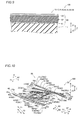
- the inner driving portions 16 and 17 each have a structure obtained by forming a piezoelectric actuator 60 on the upper surface (surface on the Z1 side) of the Si substrate 1.
- This piezoelectric actuator 60 has a structure obtained by stacking a lower electrode 61, a piezoelectric body 62, and an upper electrode 63 from the side (Z2 side) closer to the Si substrate 1, as shown in Fig. 9 .
- the lower electrode 61 is made of Ti, Pt, or the like, and formed on the upper surface of the Si substrate 1.
- wiring on the lower electrode 61 of the piezoelectric actuator 60 can be performed with respect to an arbitrary portion of the Si substrate 1.
- the thickness of the piezoelectric actuator 60 is sufficiently small with respect to the Si substrate 1, and hence in Figs. 3 , 11, and 12 , illustration of the piezoelectric actuator 60 formed in each of the driving portions 41, 43, 45, 51, 53, and 55 is omitted.
- the thickness of the lower electrode 61 is sufficiently small, and hence in the drawings other than Fig. 9 , illustration of the lower electrode 61 formed on the upper surface of the Si substrate 1 is omitted.
- the piezoelectric body 62 is made of lead zirconate titanate (PZT), and is so polarized in the thickness direction (direction Z) that the same expands/contracts upon voltage application.
- the piezoelectric body 62 is also formed on the upper surface of the lower electrode 61 of each of the support portions 42, 44, 52, and 54 (see Fig. 4 ) and the mirror support portions 46 (see Fig. 6 ) and 56 (see Fig. 7 ).
- the piezoelectric body 62 see Fig.
- the thickness of the piezoelectric body 62 is sufficiently small with respect to the Si substrate 1, and hence in Figs. 3 , 11, and 12 , illustration of the piezoelectric body 62 formed on the upper surface of each of the support portions 42, 44, 52, and 54 and the mirror support portions 46 and 56 is omitted.
- the upper electrode 63 is made of a conductive metallic material such as Al, Cr, Cu, Au, or Pt.
- a voltage for contracting the upper surface side (Z1 side) of the piezoelectric actuators 60 beyond the lower surface side (Z2 side) is applied to the driving portions 41, 43, and 45 of the driving unit 40, as shown in Fig. 10 .
- another voltage, opposite in phase to the voltage applied to the driving portions 41, 43, and 45, for contracting the lower surface side (Z2 side) of the piezoelectric actuators 60 beyond the upper surface side (Z1 side) is applied to the driving portions 51, 53, and 55 of the driving unit 50.
- the end portions 41b, 43c, and 45c on the Y2 side are located above (Z1 side) the end portions 41a, 43a, and 45a on the Y1 side, respectively, whereby the driving portions 41, 43, and 45 are deformed to warp upward.
- the end portion 41b of the driving portion 41 is inclined along arrow B1 to have the first inclination angle ⁇ 1 on the Z1 side with respect to the tangent line C0.
- the end portion 43c of the driving portion 43 is inclined along arrow B1 to have the second inclination angle ⁇ 2 on the Z1 side with respect to the tangent line C1.
- the end portions 51b, 53c, and 55c on the Y1 side are located below (Z2 side) the end portions 51a, 53a, and 55a on the Y2 side, respectively, whereby the driving portions 51, 53, and 55 are deformed to warp downward.
- the end portion 51b of the driving portion 51 is inclined along arrow B1 to have the fifth inclination angle ⁇ 5 on the Z2 side with respect to the tangent line D0.
- the end portion 53c of the driving portion 53 is inclined along arrow B1 to have the sixth inclination angle ⁇ 6 on the Z2 side with respect to the tangent line D1.
- the first inclination angle ⁇ 1 and the fifth inclination angle 05 are substantially equal to each other
- the second inclination angle ⁇ 2 and the sixth inclination angle ⁇ 6 are substantially equal to each other
- the mirror support portion 46 is inclined along arrow B1 while the same maintains the fourth inclination angle ⁇ 4 (see Fig. 11 ) on the Z1 side with respect to the tangent line C0 (see Fig. 11 ) and itself is unwarped.
- the X-directional optical scanning portion 10 (mirror 11) supported by the mirror support portion 46 on the X1 side and the Y2 side and supported by the mirror support portion 56 on the X2 side and the Y1 side is inclined along arrow B1 with respect to the horizontal plane including the tangent lines C0 and D0.
- the X-directional optical scanning portion 10, the mirror support portion 46, and the mirror support portion 56 are located substantially in the same plane while the same are inclined along arrow B1.
- a voltage for contracting the lower surface side (Z2 side) of the piezoelectric actuators 60 beyond the upper surface side (Z1 side) is applied to the driving portions 41, 43, and 45 of the driving unit 40.
- another voltage, opposite in phase to the voltage applied to the driving portions 41, 43, and 45, for contracting the upper surface side (Z1 side) of the piezoelectric actuators 60 beyond the lower surface side (Z2 side) is applied to the driving portions 51, 53, and 55 of the driving unit 50.
- the end portions 41b, 43c, and 45c on the Y2 side are located below (Z2 side) the end portions 41a, 43a, and 45a on the Y1 side, respectively, whereby the driving portions 41, 43, and 45 are deformed to warp downward.
- the end portion 41b of the driving portion 41 is inclined along arrow B2 to have the first inclination angle ⁇ 1 on the Z2 side with respect to the tangent line C0.
- the end portion 43c of the driving portion 43 is inclined along arrow B2 to have the second inclination angle ⁇ 2 on the Z2 side with respect to the tangent line C1.
- the end portions 51b, 53c, and 55c on the Y1 side are located above (Z1 side) the end portions 51a, 53a, and 55a on the Y2 side, respectively, whereby the driving portions 51, 53, and 55 are deformed to warp upward.
- the end portion 51b of the driving portion 51 is inclined along arrow B2 to have the fifth inclination angle ⁇ 5 on the Z1 side with respect to the tangent line D0.
- the end portion 53c of the driving portion 53 is inclined along arrow B2 to have the sixth inclination angle ⁇ 6 on the Z1 side with respect to the tangent line D1.
- the mirror support portion 46 is inclined along arrow B2 while the same maintains the fourth inclination angle ⁇ 4 (see Fig. 12 ) on the Z2 side with respect to the tangent line C0 (see Fig. 12 ) and itself is unwarped.
- the X-directional optical scanning portion 10 (mirror 11) is inclined along arrow B2 at the inclination angle ⁇ 4 with respect to the horizontal plane including the tangent lines C0 and D0.
- the X-directional optical scanning portion 10, the mirror support portion 46, and the mirror support portion 56 are located substantially in the same plane while the same are inclined along arrow B2.
- a voltage is so applied to the driving portions 41, 43, 45, 51, 53, and 55 of the Y-directional optical scanning portion 30 that the driving portions 41, 43, 45, 51, 53, and 55 nonresonantly drive the mirror 11 to repeat a state where the upper surface side (Z1 side) of the piezoelectric actuators 60 is contracted beyond the lower surface side (Z2 side) and a state where the lower surface side (Z2 side) is contracted beyond the upper surface side (Z1 side) at a frequency of about 60 Hz.
- the Y-directional optical scanning portion 30 inclines the mirror 11 in the direction B about the rotation center axis R2 and optically scans the object in the unshown direction Y.
- Figs. 14 and 15 are sectional views taken along the line 5000-5000 shown in Fig. 2 .
- an SOI substrates 4 having the Si substrate 1, the SiO 2 layer 2 formed on the lower surface (Z2 side) of the Si substrate 1, and the lower Si layer 3 formed on the lower surface of the SiO 2 layer 2 is prepared, as shown in Fig. 14 .
- the lower electrodes 61 (see Fig. 9 ) and the piezoelectric bodies 62 (see Fig. 9 ) are successively formed on the entire upper surface (surface of the Si substrate 1 on the Z1 side) of the SOI substrate 4 by sputtering or the like.
- the upper electrodes 63 see Fig.
- the piezoelectric actuators 60 are formed in the inner driving portions 16 and 17 and the driving portions 41, 43, 45, 51, 53, and 55.
- resist patterns are formed in positions corresponding to the inner driving portions 16 and 17, the driving portions 41, 43, 45, 51, 53, and 55, the support portions 42, 44, 52, and 54, and the mirror support portions 46 and 56 by photolithography, and wet etching or the like is thereafter performed through the resist patterns serving as masks, thereby removing portions of the piezoelectric bodies 62 formed in positions other than positions corresponding to the inner driving portions 16 and 17, the driving portions 41, 43, 45, 51, 53, and 55, the support portions 42, 44, 52, and 54, and the mirror support portions 46 and 56.
- mask patterns 5 made of Al, Cr, Cu, Au, Pt, or the like are formed in positions of the lower surface (surface of the lower Si layer 3 on the Z2 side) of the SOI substrate 4 corresponding to the frame body 20 and the unshown outer frame body by vapor deposition or the like.
- a resist pattern (not shown) is formed in a position corresponding to the vibrating mirror element 100 by photolithography and thereafter employed as a mask to remove portions of the lower electrodes 61 (see Fig. 9 ) formed in positions other than the position corresponding to the vibrating mirror element 100 by wet etching or the like.
- the lower electrode 61 is formed only on the upper surface (surface on the Z1 side) of the Si substrate 1 forming the vibrating mirror element 100.
- portions of the Si substrate 1 formed in positions other than the position corresponding to the vibrating mirror element 100 are removed by reactive ion etching (RIE) or the like, as shown in Fig. 15 .
- the mask patterns 5 are employed as masks to remove portions of the lower Si layer 3 formed in positions other than positions corresponding to the frame body 20 and the unshown outer frame body by reactive ion etching (RIE) or the like.
- portions of the SiO 2 layer 2 formed in the positions other than the position corresponding to the vibrating mirror element 100 are removed by reactive ion etching (RIE) or the like.
- RIE reactive ion etching
- the driving portion 41, the support portion 42, the driving portion 43, the support portion 44, the driving portion 45, and the mirror support portion 46 of the driving unit 40 and the driving portion 51, the support portion 52, the driving portion 53, the support portion 54, the driving portion 55, and the mirror support portion 56 of the driving unit 50, respectively, are configured to be substantially point-symmetrical to each other with respect to the center R3 of the mirror 11, whereby the X-directional optical scanning portion 10 can be supported by the driving units 40 and 50 that are substantially point-symmetrical to each other in plan view.
- the own weight of the X-directional optical scanning portion 10 can be evenly distributed to the mirror support portion 46 and the mirror support portion 56, and hence the X-directional optical scanning portion 10 can be inhibited from inclining in the non-driven state.
- the end portion 41a of the driving portion 41 on the Y1 side, the end portion 42c of the support portion 42 on the Y1 side, the end portion 43a of the driving portion 43 on the Y1 side, the end portion 44c of the support portion 44 on the Y1 side, and the end portion 45a of the driving portion 45 on the Y1 side are arranged on the Y1 side beyond the side surface of the X-directional optical scanning portion 10 on the Y1 side
- the end portion 41b of the driving portion 41 on the Y2 side, the end portion 42a of the support portion 42 on the Y2 side, the end portion 43c of the driving portion 43 on the Y2 side, the end portion 44a of the support portion 44 on the Y2 side, and the end portion 45c of the driving portion 45 on the Y2 side are arranged on the Y2 side beyond the side surface of the X-directional optical scanning portion 10 on the Y2 side, while the end portion 51a of the driving portion 51 on
- the driving portions 41, 43, 45, 51, 53, and 55 can be formed to extend from the Y1 side of the X-directional optical scanning portion 10 (mirror 11) in the direction Y toward the Y2 side thereof.
- the driving portions 41, 43, and 45 and the driving portions 51, 53, and 55 can be aligned in the direction (direction X) orthogonal to the direction Y to hold the X-directional optical scanning portion 10 therebetween in the direction X.
- the driving portions 41, 43, and 45 and the driving portions 51, 53, and 55 are not arranged on a common straight line extending in the direction Y, and hence the overall size of the vibrating mirror element 100 is not increased in the direction Y by the sum of increases in the lengths of the driving portions 41, 43, 45, 51, 53, and 55 even if the lengths of the driving portions 41, 43, 45, 51, 53, and 55 in the direction Y are increased. Consequently, the size of the vibrating mirror element 100 in the direction Y can be inhibited from increase.
- the driving units 40 and 50 are configured to be substantially point-symmetrical to each other with respect to the center R3 of the mirror 11 so that the residual stress of the driving unit 40 and the residual stress of the driving unit 50 offset each other.
- the X-directional optical scanning portion 10 can be easily inhibited from inclining with respect to the plane (horizontal plane) passing through the end portion (fixed end) 41a of the driving portion 41 on the Y1 side and the end portion (fixed end) 51a of the driving portion 51 on the Y2 side in the non-driven state even if residual stress is accumulated in the driving portions 41, 43, 45, 51, 53, and 55.
- the X-directional optical scanning portion 10 and the Y-directional optical scanning portion 30 are arranged substantially parallel to the plane (horizontal plane) passing through the end portion (fixed end) 41a of the driving portion 41 on the Y1 side and the end portion (fixed end) 51a of the driving portion 51 on the Y2 side.
- the mirror portion can be arranged substantially parallel to the horizontal plane passing through the end portion 41a of the driving portion 41 and the end portion 51a of the driving portion 51 that are not displaced in both of the driven state and the non-driven state of the driving portions 41, 43, 45, 51, 53, and 55, and hence the X-directional optical scanning portion 10 (mirror 11) can be stably inclined.
- the driving portions 41 and 51 are deformed in the warping directions opposite to each other to be driven.
- the mirror support portion 46 inclined in response to the deformation of the driving portion 41 and the mirror support portion 56 inclined in response to the deformation of the driving portion 51 can be easily inclined in the same direction, and hence the X-directional optical scanning portion 10 supported by the mirror support portion 46 and the mirror support portion 56 can be easily inclined in a prescribed direction.
- the driving portion 41, the support portion 42, the driving portion 43, the support portion 44, the driving portion 45, and the mirror support portion 46 are arranged in this order from the X1 side along the direction X while in the driving unit 50, the driving portion 51, the support portion 52, the driving portion 53, the support portion 54, the driving portion 55, and the mirror support portion 56 are arranged in this order from the X2 side along the direction X.
- the X-directional optical scanning portion 10 can be inclined to have a larger inclination angle in driving by driving the driving portions 43, 45, 53, and 55 in addition to the driving portions 41 and 51.
- the mirror support portion 46 is inclined along arrow B1 or B2 at the fourth inclination angle obtained by substantially adding the first inclination angle, the second inclination angle, and the third inclination angle with respect to the tangent line C0 (located on the horizontal plane) while the mirror support portion 56 is inclined along arrow B1 or B2 at the eighth inclination angle obtained by substantially adding the fifth inclination angle, the sixth inclination angle, and the seventh inclination angle with respect to the tangent line D0 (located on the horizontal plane).
- the mirror support portion 46 can support the X-directional optical scanning portion 10 (mirror 11) in response to the inclination of the connecting portion 41c (end portion 41b) while the mirror support portion 56 can support the X-directional optical scanning portion 10 in response to the inclination of the connecting portion 51c (end portion 51b). Furthermore, the inclination angles of the mirror support portions 46 and 56 can be further increased, and hence the inclination angle of the X-directional optical scanning portion 10 can be further increased.
- the X-directional optical scanning portion 10 is configured to be supported in the inclined state by the mirror support portions 46 and 56 while the same is located on the plane including the tangent lines C3 and D3 when the driving portions 41, 43, 45, 51, 53, and 55 are driven while being deformed.
- the X-directional optical scanning portion 10 (mirror 11) can be stably inclined while the inclination of the mirror support portion 46, the inclination of the mirror support portion 56, and the inclination of the X-directional optical scanning portion 10 are maintained to be substantially the same as each other.
- the voltage applied to the driving portions 41, 43, and 45 and the voltage applied to the driving portions 51, 53, and 55 are opposite in phase to each other, whereby the driving portions 41, 43, and 45 and the driving portions 51, 53, and 55 can be easily deformed to warp in directions different from each other.
- the end portion 41b of the driving portion 41 and the end portion 51b of the driving portion 51 can be displaced to the same extent in directions opposite to each other with reference to positions in the non-driven state
- the end portion 43c of the driving portion 43 and the end portion 53c of the driving portion 53 can be displaced to the same extent in directions opposite to each other with reference to positions in the non-driven state
- the end portion 45c of the driving portion 45 and the end portion 55c of the driving portion 55 can be displaced to the same extent in directions opposite to each other with reference to positions in the non-driven state.
- the adjacent portions are alternately successively bent on the Y1 side or the Y2 side from the mirror support portion 46 on the X2 side toward the driving portion 41 on the X1 side to be connected to each other so that the portions from the mirror support portion 46 to the driving portion 41 are continuously connected, while in the driving unit 50, the adjacent portions are alternately successively bent on the Y1 side or the Y2 side from the mirror support portion 56 on the X1 side toward the driving portion 51 on the X2 side to be connected to each other so that the portions from the mirror support portion 56 to the driving portion 51 are continuously connected.
- the driving portion 43 can be driven on the basis of the displacement of the end portion 41b (connecting portion 41c) of the driving portion 41 while the driving portion 45 can be driven on the basis of the displacement of the end portion 43c (connecting portion 43d) of the driving portion 43.
- the driving portion 53 can be driven on the basis of the displacement of the end portion 51b (connecting portion 51c) of the driving portion 51 while the driving portion 55 can be driven on the basis of the displacement of the end portion 53c (connecting portion 53d) of the driving portion 53.
- the inclination angles of the mirror support portions 46 and 56 can be further increased, and hence the inclination angle of the X-directional optical scanning portion 10 (mirror 11) can be further increased.
- the X-directional optical scanning portion 10 is provided with the mirror 11 and the inner driving portions 16 and 17 rotating the mirror 11 about the rotation center axis R1.
- the mirror 11 can accurately reflect light about the rotation center R2, and the vibrating mirror element 100 can two-dimensionally optically scan the object by the rotation about the rotation center R1 and the rotation about the rotation center axis R2.
- the X-directional optical scanning portion 10 is configured to resonantly drive the mirror 11 at the resonance frequency of about 30 kHz while the Y-directional optical scanning portion 30 is configured to nonresonantly drive the mirror 11 at the frequency of about 60 Hz.
- the vibrating mirror element 100 can two-dimensionally optically scan the object while the X-directional optical scanning portion 10 is configured to rotate at a larger frequency about the rotation center axis R1 than about the rotation center axis R2.
- the rotation center axis R2 passes through the middle portions of the driving portions 41 and 51 in the direction Y in the non-driven state of the driving portions 41 and 51, whereby the driving portions 41 and 51 can be driven in the direction Y in a balanced manner.
- the driving portions 16 and 17 are provided to hold the mirror therebetween in the direction X, and formed to protrude toward the mirror 11 in the vicinity of the rotation center axis R2, whereby the width of each of the driving portions 16 and 17 in the vicinity of the rotation center axis R2 is increased, and hence the mechanical strength of each of the driving portions 16 and 17 deformed in driving can be increased.
- the X-directional optical scanning portion 10 is provided with the frame body 20 supported by the mirror support portions 46 and 56, and the frame body 20 is configured to have the thickness larger than the thicknesses of other portions of the X-directional optical scanning portion 10, whereby the frame body 20 can be inhibited from twisting. Consequently, the X-directional optical scanning portion 10 can be inclined at a prescribed inclination angle in a stable state.
- the driving units 40 and 50 (Y-directional optical scanning portion 30) and the X-directional optical scanning portion 10 are integrally formed on the common Si substrate 1, whereby no connection between the driving units 40 and 50 (Y-directional optical scanning portion 30) and the X-directional optical scanning portion 10 may be made separately, and hence the steps of manufacturing the vibrating mirror element 100 can be simplified.
- the vibrating mirror element 100 includes the X-directional optical scanning portion 10 and the Y-directional optical scanning portion 30 and rotates the mirror 11 in the direction A and the direction B (two-dimensionally)
- the present invention is not restricted to this.
- no X-directional optical scanning portion but a Y-directional optical scanning portion 230 and a mirror 211 may be provided to rotate the mirror 211 only in the direction B (see Fig. 1 ) (one-dimensionally) according to this embodiment, as in a vibrating mirror element 200 according to a first modification shown in Fig. 16 .
- the mirror 211 is connected with an end portion 246d on a Y1 side of a mirror support portion 246 of a driving unit 240 on an X1 side and a Y2 side, and connected with an end portion 256d on the Y2 side of a mirror support portion 256 of a driving unit 250 on an X2 side and the Y1 side.
- the mirror 211 can be inclined in the direction B.
- the driving units 240 and 250 are point-symmetrical to each other with respect to the center R3 of the mirror 211.
- the mirror 211 is an example of the "mirror portion" in the present invention.
- insulating layers 370 and wiring portions 380 may be further formed on the upper surfaces of piezoelectric actuators 60 formed in driving portions 341, 343, 345, 351, 353, and 355 to extend in the direction Y (see Fig. 1 ), and contact holes 370a may be formed in the insulating layers 370, as in a vibrating mirror element 300 according to a second modification shown in Fig. 17 .
- upper electrodes 63 of the piezoelectric actuators 60 and the wiring portions 380 can be connected to each other through the contact holes 370a, and hence a voltage can be easily applied to the upper electrodes 63 of the piezoelectric actuators 60 of the driving portions 341, 343, 345, 351, 353, and 355 through the wiring portions 380 and the contact holes 370a.
- the insulating layers 370 and the wiring portions 380 are further formed on the upper surfaces of piezoelectric bodies 62 arranged on the upper surfaces of support portions 342, 344, 352, and 354 and mirror support portions 346 and 356, as shown in Fig. 18 . As shown in Figs.
- the wiring portions 380 may be connected to each other on connecting portions (connecting portions 41c, 42b, 42d, 43b, 43d, 44b, 44d, 45b, 45d, 46b, 51c, 52b, 52d, 53b, 53d, 54b, 54d, 55b, 55d, 56b) between the adjacent driving portions and support portions or mirror support portions.
- connecting portions 41c, 42b, 42d, 43b, 43d, 44b, 44d, 45b, 45d, 46b, 51c, 52b, 52d, 53b, 53d, 54b, 54d, 55b, 55d, 56b between the adjacent driving portions and support portions or mirror support portions.
- the same voltage can be easily applied to the driving portions 341, 343, and 345 of a driving unit 340 while the same voltage can be easily applied to the driving portions 351, 353, and 355 of a driving unit 350.
- an inner driving portion 16 see Fig.
- the piezoelectric actuators 60 are examples of the "driving section" in the present invention, and the upper electrodes 63 are examples of the "electrode" in the present invention.
- not more than one or at least three first support portions and not more than one or at least three third driving portions may be provided between the first driving portion and the first mirror support portion, or not more than one or at least three second support portions and not more than one or at least three fourth driving portions may be provided between the second driving portion and the second mirror support portion.
- the second support portions must be provided to be point-symmetrical to the first support portions with respect to the center of the mirror portion, and the fourth driving portions must be provided to be point-symmetrical to the third driving portions with respect to the center of the mirror portion.
- the present invention is not restricted to this. According to the present invention, no connecting portion may be provided in the vicinity of the end portion of the driving portion so far as a connecting portion is provided on the side of the free end of the driving portion.
- the piezoelectric body 62 is made of lead zirconate titanate (PZT)
- the piezoelectric body may be made of a piezoelectric material, other than PZT, consisting of an oxide mainly composed of lead, titanium and/or zirconium or another piezoelectric material.
- the piezoelectric body may be made of a piezoelectric material such as zinc oxide (ZnO), lead lanthanate zirconate titanate ((Pb,La) (Zr,Ti)O 3 ), potassium niobate (KNbO 3 ), or sodium niobate (NaNbO 3 ).
- the present invention is not restricted to this. According to the present invention, no residual stress may be accumulated in the first driving portion, the second driving portion, the third driving portion, and the fourth driving portion.
- the present invention is not restricted to this.
- the portions from the first (second) mirror support portion to the first (second) driving portion may not be continuously connected.
- a pair of the driving units must be point-symmetrical to each other with respect to the center of the mirror portion, and the first (second) driving portion must be cantilevered.
- the present invention is not restricted to this.
- the number of the first (second) support portions and the number of the third (fourth) driving portions provided in the driving unit may be different from each other.
- the second support portions and the fourth driving portions that are formed must be point-symmetrical to the first support portions and the third driving portions, respectively, with respect to the center of the mirror portion.
- the first inclination angle ⁇ 1 and the fifth inclination angle ⁇ 5 may not be equal to each other
- the second inclination angle ⁇ 2 and the sixth inclination angle ⁇ 6 may not be equal to each other
- the third inclination angle ⁇ 3 and the seventh inclination angle ⁇ 7 may not be equal to each other, so far as the fourth inclination angle ⁇ 4 and the eighth inclination angle ⁇ 8 are equal to each other.
- the Y-directional optical scanning portion 30 is configured to nonresonantly drive the mirror 11 at the frequency of about 60 Hz
- the present invention is not restricted to this.
- the Y-directional optical scanning portion may be configured to resonantly drive the mirror.
- the Y-directional optical scanning portion nonresonantly drives the mirror at a frequency of at least about 30 Hz and not more than about 120 Hz.
- the present invention is not restricted to this.
- the Y-directional optical scanning portion and the X-directional optical scanning portion may not be integrally formed, or the driving portions, the support portions, and the mirror support portions of the driving units may not be integrally formed.
- the Y-directional optical scanning portion may be formed by preparing the driving portions, the support portions, and the mirror support portions separately, and thereafter bonding the same to each other.
- the inner driving portions 16 and 17 and the driving portions 41, 43, 45, 51, 53, and 55 include the piezoelectric actuators 60 each having the structure obtained by stacking the lower electrode 61, the piezoelectric body 62, and the upper electrode 63
- the present invention is not restricted to this.
- the inner driving portions and the driving portions may be configured to be driven by drivers other than the piezoelectric actuators.
- the inner driving portions and the driving portions may be driven by drivers, made of an elastomer, held between electrodes. In this case, a voltage is so applied between the electrodes that the electrodes attract each other thereby compressing the elastomer and deforming the drivers.
Landscapes
- Physics & Mathematics (AREA)
- General Physics & Mathematics (AREA)
- Optics & Photonics (AREA)
- Engineering & Computer Science (AREA)
- Computer Hardware Design (AREA)
- Microelectronics & Electronic Packaging (AREA)
- Mechanical Light Control Or Optical Switches (AREA)
- Micromachines (AREA)
- Mechanical Optical Scanning Systems (AREA)
Abstract
This vibrating mirror element (100) includes a mirror portion (10), a first driving portion (41), being cantilevered, including a first fixed end (41a) formed on a first side of a first direction and a first free end (41b) formed on a second side thereof, and linearly extending, a first mirror support portion (46) capable of supporting the mirror portion (10) in an inclined state, a second driving portion (51), being cantilevered, including a second fixed end (51a) formed on the second side of the first direction and a second free end (51b) formed on the first side thereof, being point-symmetrical to the first driving portion with respect to the center of a mirror, and linearly extending, and a second mirror support portion (56) being point-symmetrical to the first mirror support portion with respect to the center of the mirror and capable of supporting the mirror portion in an inclined state.
Description
- The present invention relates to a vibrating mirror element, and more particularly, it relates to a vibrating mirror element including a driving portion.
- In general, a vibrating mirror element including a driving portion is known. Such a vibrating mirror element is disclosed in Japanese Patent Laying-Open Nos.
2009-169290 2007-188073 - In the aforementioned Japanese Patent Laying-Open No.
2009-169290 - In the aforementioned Japanese Patent Laying-Open No.
2007-188073 -
- Patent Document 1: Japanese Patent Laying-Open No.
2009-169290 - Patent Document 2: Japanese Patent Laying-Open No.
2007-188073 - However, in the optical deflector described in the aforementioned Patent Laying-Open No.
2009-169290 - In the two-axis micro scanner described in the aforementioned Japanese Patent Laying-Open No.
2007-188073 - The present invention has been proposed in order to solve the aforementioned problems, and an object of the present invention is to provide a vibrating mirror element capable of being inhibited from lengthening in a first direction and capable of inhibiting a mirror portion from inclining in a non-driven state.
- A vibrating mirror element according to an aspect of the present invention includes a mirror portion, a deformable first driving portion, being cantilevered, including a first fixed end formed on a first side of a first direction beyond a first end portion of the mirror portion on the first side of the first direction and a first free end formed on a second side of the first direction beyond a second end portion of the mirror portion on the second side of the first direction, and linearly extending along the first direction, a first mirror support portion capable of supporting the mirror portion in a state where the mirror portion is inclined in response to an inclination of the first free end in driving, a deformable second driving portion, being cantilevered, including a second fixed end formed on the second side of the first direction beyond the second end portion of the mirror portion on the second side of the first direction and a second free end formed on the first side of the first direction beyond the first end portion of the mirror portion on the first side of the first direction, being point-symmetrical to the first driving portion with respect to the center of the mirror portion, and linearly extending along the first direction, and a second mirror support portion being point-symmetrical to the first mirror support portion with respect to the center of the mirror portion and capable of supporting the mirror portion in a state where the mirror portion is inclined in response to an inclination of the second free end in driving.
- In the vibrating mirror element according to the aspect of the present invention, as hereinabove described, the second driving portion is configured to be point-symmetrical to the first driving portion with respect to the center of the mirror portion, and the second mirror support portion is configured to be point-symmetrical to the first mirror support portion with respect to the center of the mirror portion, whereby the mirror portion can be supported by the first driving portion and the second driving portion that are point-symmetrical to each other and the first mirror support portion and the second mirror support portion that are point-symmetrical to each other in plan view. Thus, the own weight of the mirror portion can be evenly distributed to the first mirror support portion and the second mirror support portion, and hence the mirror portion can be inhibited from inclining in a non-driven state. Furthermore, the first driving portion and the second driving portion are point-symmetrical to each other so that the residual stress of the first driving portion and the residual stress of the second driving portion can offset each other, if residual stress is accumulated in the first driving portion and the second driving portion. Thus, the mirror portion can be inhibited from inclining in the non-driven state also according to this structure.
- Furthermore, in the aforementioned vibrating mirror element according to the aspect of the present invention, the first fixed end of the first driving portion linearly extending along the first direction is formed on the first side of the first direction beyond the first end portion of the mirror portion on the first side of the first direction, the first free end thereof is formed on the second side of the first direction beyond the second end portion of the mirror portion on the second side of the first direction, the second fixed end of the second driving portion linearly extending along the first direction is formed on the second side of the first direction beyond the second end portion of the mirror portion on the second side of the first direction, and the second free end thereof is formed on the first side of the first direction beyond the first end portion of the mirror portion on the first side of the first direction, whereby the first driving portion and the second driving portion can be formed to extend from a first side of the mirror portion in the first direction toward a second side thereof. In other words, the first driving portion and the second driving portion can be aligned in a direction (second direction) orthogonal to the first direction to hold the mirror portion therebetween in the second direction. Thus, the first driving portion and the second driving portion are not arranged on a common straight line extending in the first direction, and hence the overall size of the vibrating mirror element is not increased in the first direction by the sum of increases in the lengths of the first driving portion and the second driving portion even if the lengths of the first driving portion and the second driving portion in the first direction are increased. Consequently, the size of the vibrating mirror element in the first direction can be inhibited from increase.
- Preferably in the aforementioned vibrating mirror element according to the aspect, residual stress is accumulated in the first driving portion and the second driving portion, and the residual stress of the first driving portion and the residual stress of the second driving portion being point-symmetrical to the first driving portion with respect to the center of the mirror portion offset each other, so that the mirror portion is arranged parallel to a plane passing through the first fixed end of the first driving portion and the second fixed end of the second driving portion in the non-driven state of the first driving portion and the second driving portion. According to this structure, the mirror portion can be easily inhibited from inclining with respect to the plane passing through the first fixed end of the first driving portion and the second fixed end of the second driving portion in the non-driven state even if residual stress is accumulated in the first driving portion and the second driving portion.
- Preferably in the aforementioned vibrating mirror element according to the aspect, the first driving portion further includes a first connecting portion formed on the side of the first free end, the second driving portion further includes a second connecting portion formed on the side of the second free end, and the first mirror support portion is configured to be capable of supporting the mirror portion in a state where the mirror portion is inclined in response to an inclination of the first connecting portion while the second mirror support portion is configured to be capable of supporting the mirror portion in a state where the mirror portion is inclined in response to an inclination of the second connecting portion. According to this structure, the first mirror support portion can support the mirror portion while at least the inclination of the first connecting portion is maintained, and the second mirror support portion can support the mirror portion while at least the inclination of the second connecting portion is maintained.
- Preferably in the aforementioned vibrating mirror element according to the aspect, the first mirror support portion, the second mirror support portion, and the mirror portion are configured to be located on the same plane in an inclined state when the first driving portion and the second driving portion are driven while being deformed. According to this structure, the mirror portion can be stably inclined while the inclination of the first mirror support portion inclined in response to the inclination of the first driving portion, the inclination of the second mirror support portion inclined in response to the inclination of the second driving portion, and the inclination of the mirror portion are maintained to be the same as each other.
- Preferably in the aforementioned vibrating mirror element according to the aspect, the first driving portion and the second driving portion are configured to be deformed in warping directions opposite to each other to be driven. According to this structure, in the structure in which the first mirror support portion and the second mirror support portion are arranged to be point-symmetrical to each other, the first mirror support portion inclined in response to the deformation of the first driving portion and the second mirror support portion inclined in response to the deformation of the second driving portion can be easily inclined in the same direction, and hence the mirror portion supported by the first mirror support portion and the second mirror support portion can be easily inclined in a prescribed direction.
- Preferably in the aforementioned vibrating mirror element according to the aspect, the first driving portion and the second driving portion are configured to be driven by voltage application, and voltages opposite in phase to each other are applied to the first driving portion and the second driving portion. According to this structure, the first driving portion and the second driving portion can be easily deformed to warp in directions different from each other. Thus, the first free end of the first driving portion and the second free end of the second driving portion can be displaced to the same extent in directions opposite to each other with reference to positions thereof in the non-driven state. Consequently, the first mirror support portion inclined in response to the inclination of the first free end of the first driving portion and the second mirror support portion being point-symmetrical to the first mirror support portion and inclined in response to the inclination of the second free end of the second driving portion can be inclined at substantially the same inclination angle. Therefore, the mirror portion supported by the first mirror support portion and the second mirror support portion can be inclined in the prescribed direction.
- Preferably, the aforementioned vibrating mirror element according to the aspect further includes at least one deformable third driving portion arranged between the first driving portion and the first mirror support portion and linearly extending along the first direction, an inclinable first support portion, the number of which is equal to the number of the third driving portions, arranged between the first driving portion and the first mirror support portion and linearly extending along the first direction, a deformable fourth driving portion being point-symmetrical to the third driving portion with respect to the center of the mirror portion, arranged between the second driving portion and the second mirror support portion, and linearly extending along the first direction, and an inclinable second support portion being point-symmetrical to the first support portion with respect to the center of the mirror portion, arranged between the second driving portion and the second mirror support portion, and linearly extending along the first direction. According to this structure, the overall vibrating mirror element further including the third driving portion, the first support portion, the fourth driving portion, and the second support portion can be configured to be point-symmetrical, and hence the first mirror support portion and the second mirror support portion being point-symmetrical to the first mirror support portion with respect to the center of the mirror portion can equally support the mirror portion. Furthermore, in addition to the first driving portion and the second driving portion, the third driving portion and the fourth driving portion are driven, whereby the mirror portion can be inclined to have a larger inclination angle in driving.
- Preferably in this case, the first mirror support portion, the second mirror support portion, the first support portion, and the second support portion are configured to be applied with no voltage and to be unwarped by the absence of a voltage. According to this structure, the first mirror support portion, the second mirror support portion, the first support portion, and the second support portion can maintain inclination angles without warping.
- Preferably in the aforementioned structure further including the third driving portion and the fourth driving portion, the first driving portion, the second driving portion, the third driving portion, and the fourth driving portion are configured to be driven by voltage application, and a voltage applied to the first driving portion and the third driving portion and a voltage applied to the second driving portion and the fourth driving portion are opposite in phase to each other. According to this structure, the first and third driving portions and the second and fourth driving portions can be easily deformed to warp in directions different from each other. Thus, the first free end of the first driving portion and the second free end of the second driving portion can be displaced to the same extent in the directions opposite to each other with reference to the positions thereof in the non-driven state. Furthermore, the third driving portion and the fourth driving portion can be displaced to the same extent in directions opposite to each other with reference to positions thereof in a non-driven state. Consequently, the first mirror support portion and the second mirror support portion being point-symmetrical to the first mirror support portion can be inclined at substantially the same inclination angle. Therefore, the mirror portion supported by the first mirror support portion and the second mirror support portion can be easily inclined to have a large inclination angle in the prescribed direction.
- Preferably in the aforementioned structure further including the third driving portion and the fourth driving portion, the third driving portion and the first support portion are connected to each other by alternately successively bending adjacent portions on either the first side of the first direction or the second side thereof in a state where the third driving portion and the first support portion are alternately arranged from the side of the first mirror support portion toward the side of the first driving portion along the second direction orthogonal to the first direction, so that portions from the first mirror support portion to the first driving portion are continuously connected, and the fourth driving portion and the second support portion are connected to each other by alternately successively bending adjacent portions on either the first side of the first direction or the second side thereof in a state where the fourth driving portion and the second support portion are alternately arranged from the side of the second mirror support portion toward the side of the second driving portion along the second direction, so that portions from the second mirror support portion to the second driving portion are continuously connected. According to this structure, the third driving portion can be driven on the basis of the displacement of the connecting portion of the first driving portion and the first support portion while the fourth driving portion can be driven on the basis of the displacement of the connecting portion of the second driving portion and the second support portion, and hence the inclination angles of the first mirror support portion and the second mirror support portion can be further increased. Thus, the inclination angle of the mirror portion can be further increased.
- Preferably in the aforementioned vibrating mirror element including the third driving portion, the first support portion, the fourth driving portion, and the second support portion, the first driving portion further includes a first connecting portion formed on the side of the first free end, the second driving portion further includes a second connecting portion formed on the side of the second free end, the third driving portion includes a third connecting portion connected with the first support portion or the first mirror support portion adjacent thereto on a side closer to the mirror portion in the second direction, the fourth driving portion includes a fourth connecting portion connected with the second support portion or the second mirror support portion adjacent thereto on a side closer to the mirror portion in the second direction, the first driving portion is configured to be connected with the first support portion adjacent thereto on the first connecting portion while the second driving portion is configured to be connected with the second support portion adjacent thereto on the second connecting portion, the inclination angle of the first mirror support portion with respect to the tangent line of the first fixed end of the first driving portion is the sum of the inclination angle of the first connecting portion with respect to the tangent line of the first fixed end of the first driving portion and the inclination angle of the third connecting portion of the third driving portion with respect to the first support portion adjacently located on a side closer to the first driving portion in the second direction, and the inclination angle of the second mirror support portion with respect to the tangent line of the second fixed end of the second driving portion is the sum of the inclination angle of the second connecting portion with respect to the tangent line of the second fixed end of the second driving portion and the inclination angle of the fourth connecting portion of the fourth driving portion with respect to the second support portion adjacently located on a side closer to the second driving portion in the second direction. According to this structure, the inclination angle of the first mirror support portion with respect to the tangent line of the first fixed end can be obtained by adding the inclination angle based on the first driving portion and the inclination angle based on the third driving portion while the inclination angle of the second mirror support portion with respect to the tangent line of the second fixed end can be obtained by adding the inclination angle based on the second driving portion and the inclination angle based on the fourth driving portion, and hence the inclination angles of the first mirror support portion and the second mirror support portion can be further increased. Thus, the inclination angle of the mirror portion can be further increased.
- Preferably in this case, the third driving portion includes a fifth connecting portion connected with the first support portion adjacent thereto on the side closer to the first driving portion in the second direction, the fourth driving portion includes a sixth connecting portion connected with the second support portion adjacent thereto on the side closer to the second driving portion in the second direction, when the third driving portion is applied with a voltage to be driven, the first support portion is undeformed, and the third driving portion is deformed with reference to the fifth connecting portion, and when the fourth driving portion is applied with a voltage to be driven, the second support portion is undeformed, and the fourth driving portion is deformed with reference to the sixth connecting portion. According to this structure, the third driving portion (fourth driving portion) can be deformed with reference to the fifth connecting portion (sixth connecting portion) to be further inclined with respect to the tangent line of the first fixed end of the first driving portion (second fixed end of the second driving portion). Thus, the inclination angles of the first mirror support portion and the second mirror support portion can be easily further increased. Consequently, the inclination angle of the mirror portion can be further increased.
- Preferably in the aforementioned structure in which the third driving portion and the fourth driving portion include the third connecting portion and the fourth connecting portion, respectively, the inclination angle of the first connecting portion with respect to the tangent line of the first fixed end of the first driving portion is equal to the inclination angle of the second connecting portion with respect to the tangent line of the second fixed end of the second driving portion, and the inclination angle of the third connecting portion of the third driving portion with respect to the first support portion adjacently located on the side closer to the first driving portion in the second direction is equal to the inclination angle of the fourth connecting portion of the fourth driving portion with respect to the second support portion adjacently located on the side closer to the second driving portion in the second direction. According to this structure, the sum of the inclination angle of the first connecting portion with respect to the tangent line of the first fixed end of the first driving portion and the inclination angle of the third connecting portion of the third driving portion with respect to the first support portion adjacently located on the side closer to the first driving portion in the second direction and the sum of the inclination angle of the second connecting portion with respect to the tangent line of the second fixed end of the second driving portion and the inclination angle of the fourth connecting portion of the fourth driving portion with respect to the second support portion adjacently located on the side closer to the second driving portion in the second direction can be rendered equal to each other. Thus, the inclination angle of the first mirror support portion and the inclination angle of the second mirror support portion can be rendered equal to each other.
- Preferably in the aforementioned vibrating mirror element according to the aspect, the mirror portion is configured to rotate about a first rotation center axis, and the mirror portion includes a mirror and a fifth driving portion rotating the mirror about a second rotation center axis orthogonal to the first rotation center axis in the in-plane direction of the mirror. According to this structure, the mirror can accurately reflect light about the first rotation center, and the vibrating mirror element capable of two-dimensionally optically scanning an object can be obtained.
- Preferably in this case, the first driving portion and the second driving portion are configured to rotate the mirror portion about the first rotation center axis on the basis of a first frequency, and the fifth driving portion is configured to rotate the mirror about the second rotation center axis on the basis of a second frequency larger than the first frequency. According to this structure, the vibrating mirror element can two-dimensionally optically scan the object while the mirror portion is configured to rotate at a larger frequency about the second rotation center axis than about the first rotation center axis.
- Preferably in the aforementioned structure in which the mirror portion rotates about the first rotation center axis, the first rotation center axis passes through middle portions of the first driving portion and the second driving portion in the first direction in the non-driven state of the first driving portion and the second driving portion. According to this structure, the first driving portion and the second driving portion can be driven in the first direction in a balanced manner.
- Preferably in the aforementioned structure in which the mirror portion rotates about the first rotation center axis, a pair of the fifth driving portions are provided to hold the mirror therebetween in the second direction orthogonal to the first direction, and formed to protrude toward the mirror in the vicinity of the first rotation center axis. According to this structure, the width of the fifth driving portion in the vicinity of the first rotation center axis is increased, and hence the mechanical strength of the fifth driving portion deformed in driving can be increased.
- Preferably in the aforementioned structure in which the mirror portion rotates about the first rotation center axis, the mirror portion includes a frame body supported by the first mirror support portion and the second mirror support portion, and the frame body has a thickness larger than the thicknesses of other portions of the mirror portion. According to this structure, the mechanical strength of the frame body is increased, and hence the frame body can be inhibited from twisting. Consequently, the mirror portion can be inclined at a prescribed inclination angle in a stable state.
- Preferably in the aforementioned vibrating mirror element according to the aspect, the first driving portion, the first mirror support portion, the second driving portion, the second mirror support portion, and the mirror portion are integrally formed. According to this structure, no connection between each portion may be made separately, and hence the number of steps of manufacturing the vibrating mirror element can be reduced.
- Preferably in the aforementioned vibrating mirror element according to the aspect, each of the first driving portion and the second driving portion further includes a driving section having an electrode, an insulating layer formed on a surface of the driving section and having a contact hole, and a wiring portion formed to extend on a surface of the insulating layer and connected with the electrode of the driving section through the contact hole. According to this structure, a voltage can be easily applied to the electrode of the driving section of each of the first driving portion and the second driving portion through the wiring portion and the contact hole.
-
- [
Fig. 1 ] A perspective view showing the structure of a vibrating mirror element according to an embodiment of the present invention. - [
Fig. 2 ] A plan view showing the structure of the vibrating mirror element according to the embodiment of the present invention. - [
Fig. 3 ] A side elevational view of the vibrating mirror element shown inFig. 2 as viewed in a direction E (direction F). - [
Fig. 4 ] An enlarged sectional view of the vibrating mirror element taken along the line 1000-1000 shown inFig. 2 . - [
Fig. 5 ] An enlarged sectional view of the vibrating mirror element taken along the line 2000-2000 shown inFig. 2 . - [
Fig. 6 ] An enlarged sectional view of the vibrating mirror element taken along the line 3000-3000 shown inFig. 2 . - [
Fig. 7 ] An enlarged sectional view of the vibrating mirror element taken along the line 4000-4000 shown inFig. 2 . - [
Fig. 8 ] An enlarged sectional view of the vibrating mirror element taken along the line 5000-5000 shown inFig. 2 . - [
Fig. 9 ] An enlarged sectional view showing a portion around a piezoelectric actuator of the vibrating mirror element according to the embodiment of the present invention. - [
Fig. 10 ] A perspective view showing a state where the vibrating mirror element according to the embodiment of the present invention is inclined at a prescribed inclination angle along arrow B1. - [
Fig. 11 ] A side elevational view showing the state where the vibrating mirror element according to the embodiment of the present invention is inclined at the prescribed inclination angle. - [
Fig. 12 ] A side elevational view showing the state where the vibrating mirror element according to the embodiment of the present invention is inclined at the prescribed inclination angle. - [
Fig. 13 ] A perspective view showing a state where the vibrating mirror element according to the embodiment of the present invention is inclined at a prescribed inclination angle along arrow B2. - [
Fig. 14 ] A sectional view showing a step of manufacturing the vibrating mirror element according to the embodiment of the present invention. - [
Fig. 15 ] A sectional view showing a step of manufacturing the vibrating mirror element according to the embodiment of the present invention. - [
Fig. 16 ] A plan view showing the structure of a vibrating mirror element according to a first modification of the embodiment of the present invention. - [
Fig. 17 ] An enlarged sectional view showing the structure of a driving portion of a Y-directional optical scanning portion of a vibrating mirror element according to a second modification of the embodiment of the present invention. - [
Fig. 18 ] An enlarged sectional view showing the structure of a support portion or a mirror support portion of the Y-directional optical scanning portion of the vibrating mirror element according to the second modification of the embodiment of the present invention. - [
Fig. 19 ] A sectional view showing connecting portions on a Y2 side of the vibrating mirror element according to the second modification of the embodiment of the present invention. - [
Fig. 20 ] A sectional view showing connecting portions on a Y1 side of the vibrating mirror element according to the second modification of the embodiment of the present invention. - An Embodiment embodying the present invention is now described on the basis of the drawings.
- First, the structure of a vibrating
mirror element 100 according to the embodiment of the present invention is described with reference toFigs. 1 to 9 . - The vibrating
mirror element 100 according to the embodiment of the present invention includes an X-directionaloptical scanning portion 10 to optically scan an object in a direction X with amirror 11 described later and a Y-directionaloptical scanning portion 30 to optically scan an object in a direction Y orthogonal to the direction X with themirror 11, as shown inFigs. 1 to 3 . The X-directionaloptical scanning portion 10 and the Y-directionaloptical scanning portion 30 are integrally formed on acommon Si substrate 1 having a thickness t1 of about 0.1 mm, as shown inFigs. 4 to 8 . The X-directionaloptical scanning portion 10 is an example of the "mirror portion" in the present invention. - The vibrating
mirror element 100 is built into a device optically scanning an object, such as an unshown projector, and configured to optically scan an object in the direction X with the X-directionaloptical scanning portion 10 and optically scan the object in the direction Y with the Y-directionaloptical scanning portion 30. The X-directionaloptical scanning portion 10 is configured to resonantly drive themirror 11 at a resonance frequency of about 30 kHz, while the Y-directionaloptical scanning portion 30 is configured to nonresonantly drive themirror 11 at a frequency of about 60 Hz. The Y-directionaloptical scanning portion 30 is so configured to nonresonantly drive themirror 11 that there is no change in resonance frequency resulting from temperature change around the vibratingmirror element 100, whereby the same can stably drive themirror 11 described later. The resonance frequency of about 30 kHz is an example of the "second frequency" in the present invention, and the frequency of about 60 Hz is an example of the "first frequency" in the present invention. - As shown in
Figs. 4 and8 , while the X-directionaloptical scanning portion 10 and the Y-directionaloptical scanning portion 30 excluding aframe body 20 described later each have a thickness t1 of about 0.1 mm in a direction Z, theframe body 20 has a thickness t2 of about 0.5 mm larger than t1. In other words, theframe body 20 has a thickness larger than the thicknesses of other portions of the X-directionaloptical scanning portion 10. Theframe body 20 is constituted by theSi substrate 1 having the thickness t1 of about 0.1 mm, a thin SiO2 layer 2 formed on the lower surface (on a Z2 side) of theSi substrate 1, and alower Si layer 3 having a thickness of about 0.4 mm formed on the lower surface of the SiO2 layer 2. - The X-directional
optical scanning portion 10 includes themirror 11, torsionallydeformable torsion bars mirror 11, aninclinable bar 14 connected with thetorsion bar 12, aninclinable bar 15 connected with thetorsion bar 13,inner driving portions bars portions inner driving portions frame body 20, as shown inFigs. 1 and 2 . The frame body 20 (X-directional optical scanning portion 10) has a length L1 of about 5 mm in the direction Y and a length L2 of about 4 mm in the direction X, as shown inFig. 2 . Theinner driving portions - The
mirror 11 and the torsion bars 12 and 13 are configured to incline beyond inclinations of thebars mirror element 100 is so configured that both a rotation center axis R1 for optically scanning the object in the direction X and a rotation center axis R2 for optically scanning the object in the direction Y pass through the center R3 of themirror 11. This center R3 of themirror 11 is located in the center of the X-directionaloptical scanning portion 10 in the directions X and Y. The rotation center axis R1 is an example of the "second rotation center axis" in the present invention, and the rotation center axis R2 is an example of the "first rotation center axis" in the present invention. The direction Y is an example of the "first direction" in the present invention, and the direction X is an example of the "second direction" in the present invention. - As shown in
Fig. 1 , theinner driving portions mirror 11 therebetween in the direction X. Theinner driving portions portions optical scanning portion 10 is configured to be capable of inclining themirror 11 along arrow A1 or A2 about the rotation center axis R1 (seeFig. 2 ) by deforming theinner driving portions optical scanning portion 10 is configured to vibrate themirror 11 in a direction A about the rotation center axis R1 and to optically scan the object by repeating the deforming operation. Theinner driving portions mirror 11 in the vicinity of the rotation center axis R1. The detailed structure of theinner driving portions - The Y-directional
optical scanning portion 30 includes a drivingunit 40 formed on the X1 side of the X-directionaloptical scanning portion 10 and a drivingunit 50 formed on the X2 side of the X-directionaloptical scanning portion 10, as shown inFig. 2 . In other words, the drivingunits optical scanning portion 10 therebetween in the direction X. - According to this embodiment, in the driving
unit 40, a drivingportion 41, asupport portion 42, a drivingportion 43, asupport portion 44, a drivingportion 45, and amirror support portion 46 are arranged in this order from an X1 side toward an X2 side along the direction X. In the drivingunit 50, a drivingportion 51, asupport portion 52, a drivingportion 53, asupport portion 54, a drivingportion 55, and amirror support portion 56 are arranged in this order from the X2 side toward the X1 side along the direction X. The drivingportion 41, thesupport portion 42, the drivingportion 43, thesupport portion 44, the drivingportion 45, and themirror support portion 46 are formed to linearly extend in the direction Y, and the drivingportion 51, thesupport portion 52, the drivingportion 53, thesupport portion 54, the drivingportion 55, and themirror support portion 56 are formed to linearly extend in the direction Y. The drivingportion 41 is an example of the "first driving portion" in the present invention, and the drivingportion 51 is an example of the "second driving portion" in the present invention. Themirror support portion 46 is an example of the "first mirror support portion" in the present invention, and themirror support portion 56 is an example of the "second mirror support portion" in the present invention. Thesupport portions support portions portions portions - According to this embodiment, the driving
units mirror 11, as shown inFig. 2 . In other words, the drivingportion 51, thesupport portion 52, the drivingportion 53, thesupport portion 54, the drivingportion 55, and themirror support portion 56 of the drivingunit 50 are arranged in such positional relation that the same substantially overlap with the drivingportion 41, thesupport portion 42, the drivingportion 43, thesupport portion 44, the drivingportion 45, and themirror support portion 46, respectively, when rotated by 180° on the center R3 of themirror 11. The specific arrangement of the drivingunits - Residual stress is accumulated in the driving unit 40 (driving
portions portions units mirror 11, whereby the residual stress of the drivingunit 40 and the residual stress of the drivingunit 50 can offset each other. - The driving
portions support portions mirror support portions mirror 11 passes through substantially middle portions of the drivingportions support portions portions - The driving
portions portions portions - An
end portion 41a of the drivingportion 41 of the drivingunit 40 on a Y1 side is fixed by an unshown outer frame body. In other words, the drivingportion 41 has a cantilever structure having theend portion 41a on the Y1 side serving as a fixed end and anend portion 41b on a Y2 side serving as a free end. Thus, the drivingportion 41 is deformed to warp when the same is driven, whereby theend portion 41b is displaced in the direction Z (seeFig. 1 ) so that the drivingportion 41 is inclined. At this time, theend portion 41a that is a fixed end is not displaced even when the drivingportion 41 is driven. Thus, a tangent line C1 (seeFig. 3 ) at theend portion 41b that is a free end is inclined at a first inclination angle with respect to a tangent line C0 (seeFig. 3 ) at theend portion 41a that is a fixed end. According to this embodiment, the tangent line C0 is located on a horizontal plane. - A connecting
portion 41c is provided in the vicinity of theend portion 41b of the drivingportion 41 on the Y2 side. On the connectingportion 41c, the drivingportion 41 is connected with a connectingportion 42b in the vicinity of anend portion 42a of thesupport portion 42 on the Y2 side. Thesupport portion 42 is configured to be applied with no voltage and to be substantially unwarped by the absence of a voltage even if theend portion 41b of the drivingportion 41 is displaced in the direction Z (seeFig. 1 ) in a driven state of the drivingportion 41. Thus, thesupport portion 42 is located on the tangent line C1 at theend portion 41b of the drivingportion 41 that is a free end in the driven state of the drivingportion 41, whereby thesupport portion 42 is inclined at the first inclination angle with respect to the tangent line C0 at theend portion 41a of the drivingportion 41 that is a fixed end. The connectingportion 41c is an example of the "first connecting portion" in the present invention. - Furthermore, a connecting
portion 42d is provided in the vicinity of anend portion 42c of thesupport portion 42 on the Y1 side. On the connectingportion 42d, thesupport portion 42 is connected with a connectingportion 43b in the vicinity of anend portion 43a of the drivingportion 43 on the Y1 side. Thesupport portion 42 is substantially unwarped so that the connectingportion 42d is located on the tangent line C1 (seeFig. 3 ). Thus, the connectingportion 43b (endportion 43a) of the drivingportion 43 connected to thesupport portion 42 on the connectingportion 42d is located on the tangent line C1, and inclined at the first inclination angle with respect to the tangent line C0 (seeFig. 3 ). The connectingportion 43b is an example of the "fifth connecting portion" in the present invention. - The driving
portion 43 connected to thesupport portion 42 on the connectingportion 42d is configured to be deformed with reference to the connectingportion 43b (endportion 43a) on the Y1 side. Thus, the drivingportion 43 is deformed to warp when the same is driven, whereby anend portion 43c is displaced in the direction Z (seeFig. 1 ) so that the drivingportion 43 is inclined with respect to thesupport portion 42. Thus, a tangent line C2 (seeFig. 3 ) at theend portion 43c is inclined at a second inclination angle with respect to the tangent line C1 (seeFig. 3 ) at theend portion 43a serving as a reference. - A connecting
portion 43d is provided in the vicinity of theend portion 43c of the drivingportion 43 on the Y2 side. On the connectingportion 43d, the drivingportion 43 is connected with a connectingportion 44b in the vicinity of anend portion 44a of thesupport portion 44 on the Y2 side. Thesupport portion 44 is configured to be applied with no voltage and to be substantially unwarped by the absence of a voltage even if theend portion 43c of the drivingportion 43 is displaced in the direction Z (seeFig. 1 ) in a driven state of the drivingportion 43. Thus, thesupport portion 44 is located on the tangent line C2 at theend portion 43c of the drivingportion 43 in the driven state of the drivingportion 43, whereby thesupport portion 44 is inclined at the second inclination angle with respect to the tangent line C1 at theend portion 43a serving as a reference. - Furthermore, a connecting
portion 44d is provided in the vicinity of anend portion 44c of thesupport portion 44 on the Y1 side. On the connectingportion 44d, thesupport portion 44 is connected with a connectingportion 45b in the vicinity of anend portion 45a of the drivingportion 45 on the Y1 side. Thesupport portion 44 is substantially unwarped so that the connectingportion 44d is located on the tangent line C2 (seeFig. 3 ). Thus, the connectingportion 45b (endportion 45a) of the drivingportion 45 connected to thesupport portion 44 on the connectingportion 44d is located on the tangent line C2, and inclined at the second inclination angle with respect to the tangent line C1 (seeFig. 3 ). The connectingportion 45b is an example of the "fifth connecting portion" in the present invention. - The driving
portion 45 connected to thesupport portion 44 on the connectingportion 44d is configured to be deformed with reference to the connectingportion 45b (endportion 45a) on the Y1 side. Thus, the drivingportion 45 is deformed to warp when the same is driven, whereby anend portion 45c is displaced in the direction Z (seeFig. 1 ) so that the drivingportion 45 is inclined with respect to thesupport portion 44. Thus, a tangent line C3 (seeFig. 3 ) at theend portion 45c is inclined at a third inclination angle with respect to the tangent line C2 (seeFig. 3 ) at theend portion 45a serving as a reference. - A connecting
portion 45d is provided in the vicinity of theend portion 45c of the drivingportion 45 on the Y2 side. On the connectingportion 45d, the drivingportion 45 is connected with a connectingportion 46b in the vicinity of anend portion 46a of themirror support portion 46 on the Y2 side. Themirror support portion 46 is configured to be applied with no voltage and to be substantially unwarped by the absence of a voltage even if theend portion 45c of the drivingportion 45 is displaced in the direction Z (seeFig. 1 ) in a driven state of the drivingportion 45. Thus, themirror support portion 46 is located on the tangent line C3 at theend portion 45c of the drivingportion 45 in the driven state of the drivingportion 45, whereby themirror support portion 46 is inclined at the third inclination angle with respect to the tangent line C2 at theend portion 45a serving as a reference. Consequently, themirror support portion 46 is configured to be inclined along arrow B1 or B2 (seeFig. 1 ) at a fourth inclination angle obtained by substantially adding the first inclination angle, the second inclination angle, and the third inclination angle with respect to the tangent line C0 (located on the horizontal plane: seeFig. 3 ). - On an
end portion 46c on the Y1 side, themirror support portion 46 is connected with the X-directionaloptical scanning portion 10 in the vicinity of an end portion on the X1 side of the side surface on the Y2 side of theframe body 20 of the X-directionaloptical scanning portion 10. Thus, in the drivingunit 40, adjacent portions are alternately successively bent in the vicinity of the end portions on the Y1 side or the end portions on the Y2 side from themirror support portion 46 on the X2 side toward the drivingportion 41 on the X1 side to be connected to each other, so that portions from themirror support portion 46 to the drivingportion 41 are continuously connected. - As shown in
Fig. 2 , theend portion 41a of the drivingportion 41 on the Y1 side, theend portion 42c of thesupport portion 42 on the Y1 side, theend portion 43a of the drivingportion 43 on the Y1 side, theend portion 44c of thesupport portion 44 on the Y1 side, and theend portion 45a of the drivingportion 45 on the Y1 side are arranged on the Y1 side beyond the side surface of the X-directionaloptical scanning portion 10 on the Y1 side. Theend portion 41b of the drivingportion 41 on the Y2 side, theend portion 42a of thesupport portion 42 on the Y2 side, theend portion 43c of the drivingportion 43 on the Y2 side, theend portion 44a of thesupport portion 44 on the Y2 side, and theend portion 45c of the drivingportion 45 on the Y2 side are arranged on the Y2 side beyond the side surface of the X-directionaloptical scanning portion 10 on the Y2 side. - An
end portion 51a of the drivingportion 51 of the drivingunit 50 on the Y2 side is fixed by the unshown outer frame body. In other words, the drivingportion 51 has a cantilever structure having theend portion 51a on the Y2 side serving as a fixed end and anend portion 51b on the Y1 side serving as a free end. Thus, the drivingportion 51 is deformed to warp when the same is driven, whereby theend portion 51b is displaced in the direction Z (seeFig. 1 ) so that the drivingportion 51 is inclined. At this time, theend portion 51a that is a fixed end is not displaced even when the drivingportion 51 is driven. Thus, a tangent line D1 (seeFig. 3 ) at theend portion 51b that is a free end is inclined at a fifth inclination angle with respect to a tangent line D0 (seeFig. 3 ) at theend portion 51a that is a fixed end. According to this embodiment, the tangent line D0 is located on the horizontal plane. - A connecting
portion 51c is provided in the vicinity of theend portion 51b of the drivingportion 51 on the Y1 side. On the connectingportion 51c, the drivingportion 51 is connected with a connectingportion 52b in the vicinity of anend portion 52a of thesupport portion 52 on the Y1 side. Thesupport portion 52 is configured to be applied with no voltage and to be substantially unwarped by the absence of a voltage even if theend portion 51b of the drivingportion 51 is displaced in the direction Z (seeFig. 1 ) in a driven state of the drivingportion 51. Thus, thesupport portion 52 is located on the tangent line D1 at theend portion 51b of the drivingportion 51 that is a free end in the driven state of the drivingportion 51, whereby thesupport portion 52 is inclined at the fifth inclination angle with respect to the tangent line D0 at theend portion 51a of the drivingportion 51 that is a fixed end. The connectingportion 51c is an example of the "second connecting portion" in the present invention. - Furthermore, a connecting
portion 52d is provided in the vicinity of anend portion 52c of thesupport portion 52 on the Y2 side. On the connectingportion 52d, thesupport portion 52 is connected with a connectingportion 53b in the vicinity of anend portion 53a of the drivingportion 53 on the Y2 side. Thesupport portion 52 is substantially unwarped so that the connectingportion 52d is located on the tangent line D1 (seeFig. 3 ). Thus, the connectingportion 53b (endportion 53a) of the drivingportion 53 connected to thesupport portion 52 on the connectingportion 52d is located on the tangent line D1, and inclined at the fifth inclination angle with respect to the tangent line D0 (seeFig. 3 ). The connectingportion 53b is an example of the "sixth connecting portion" in the present invention. - The driving
portion 53 connected to thesupport portion 52 on the connectingportion 52d is configured to be deformed with reference to the connectingportion 53b (endportion 53a) on the Y2 side. Thus, the drivingportion 53 is deformed to warp when the same is driven, whereby anend portion 53c is displaced in the direction Z (seeFig. 1 ) so that the drivingportion 53 is inclined with respect to thesupport portion 52. Thus, a tangent line D2 (seeFig. 3 ) at theend portion 53c is inclined at a sixth inclination angle with respect to the tangent line D1 (seeFig. 3 ) at theend portion 53a serving as a reference. - A connecting
portion 53d is provided in the vicinity of theend portion 53c of the drivingportion 53 on the Y1 side. On the connectingportion 53d, the drivingportion 53 is connected with a connectingportion 54b in the vicinity of anend portion 54a of thesupport portion 54 on the Y1 side. Thesupport portion 54 is configured to be applied with no voltage and to be substantially unwarped by the absence of a voltage even if theend portion 53c of the drivingportion 53 is displaced in the direction Z (seeFig. 1 ) in a driven state of the drivingportion 53. Thus, thesupport portion 54 is located on the tangent line D2 at theend portion 53c of the drivingportion 53 in the driven state of the drivingportion 53, whereby thesupport portion 54 is inclined at the sixth inclination angle with respect to the tangent line D1 at theend portion 53a serving as a reference. - Furthermore, a connecting
portion 54d is provided in the vicinity of anend portion 54c of thesupport portion 54 on the Y2 side. On the connectingportion 54d, thesupport portion 54 is connected with a connectingportion 55b in the vicinity of anend portion 55a of the drivingportion 55 on the Y2 side. Thesupport portion 54 is substantially unwarped so that the connectingportion 54d is located on the tangent line D2 (seeFig. 3 ). Thus, the connectingportion 55b (endportion 55a) of the drivingportion 55 connected to thesupport portion 54 on the connectingportion 54d is located on the tangent line D2, and inclined at the sixth inclination angle with respect to the tangent line D1 (seeFig. 3 ). The connectingportion 55b is an example of the "sixth connecting portion" in the present invention. - The driving
portion 55 connected to thesupport portion 54 on the connectingportion 54d is configured to be deformed with reference to the connectingportion 55b (endportion 55a) on the Y2 side. Thus, the drivingportion 55 is deformed to warp when the same is driven, whereby anend portion 55c is displaced in the direction Z (seeFig. 1 ) so that the drivingportion 55 is inclined with respect to thesupport portion 54. Thus, a tangent line D3 (seeFig. 3 ) at theend portion 55c is inclined at a seventh inclination angle with respect to the tangent line D2 (seeFig. 3 ) at theend portion 55a serving as a reference. - A connecting
portion 55d is provided in the vicinity of theend portion 55c of the drivingportion 55 on the Y1 side. On the connectingportion 55d, the drivingportion 55 is connected with a connectingportion 56b in the vicinity of anend portion 56a of themirror support portion 56 on the Y1 side. Themirror support portion 56 is configured to be applied with no voltage and to be substantially unwarped by the absence of a voltage even if theend portion 55c of the drivingportion 55 is displaced in the direction Z (seeFig. 1 ) in a driven state of the drivingportion 55. Thus, themirror support portion 56 is located on the tangent line D3 at theend portion 55c of the drivingportion 55 in the driven state of the drivingportion 55, whereby themirror support portion 56 is inclined at the seventh inclination angle with respect to the tangent line D2 at theend portion 55a serving as a reference. Consequently, themirror support portion 56 is configured to be inclined along arrow B1 or B2 (seeFig. 1 ) at an eighth inclination angle obtained by substantially adding the fifth inclination angle, the sixth inclination angle, and the seventh inclination angle with respect to the tangent line D0 (located on the horizontal plane: seeFig. 3 ). - On an
end portion 56c on the Y2 side, themirror support portion 56 is connected with the X-directionaloptical scanning portion 10 in the vicinity of an end portion on the X2 side of the side surface on the Y1 side of theframe body 20 of the X-directionaloptical scanning portion 10. Thus, in the drivingunit 50, adjacent portions are alternately successively bent in the vicinity of the end portions on the Y1 side or the end portions on the Y2 side from themirror support portion 56 on the X1 side toward the drivingportion 51 on the X2 side to be connected to each other, so that portions from themirror support portion 56 to the drivingportion 51 are continuously connected. - As shown in
Fig. 2 , theend portion 51a of the drivingportion 51 on the Y2 side, theend portion 52c of thesupport portion 52 on the Y2 side, theend portion 53a of the drivingportion 53 on the Y2 side, theend portion 54c of thesupport portion 54 on the Y2 side, and theend portion 55a of the drivingportion 55 on the Y2 side are arranged on the Y2 side beyond the side surface of the X-directionaloptical scanning portion 10 on the Y2 side. Theend portion 51b of the drivingportion 51 on the Y1 side, theend portion 52a of thesupport portion 52 on the Y1 side, theend portion 53c of the drivingportion 53 on the Y1 side, theend portion 54a of thesupport portion 54 on the Y1 side, and theend portion 55c of the drivingportion 55 on the Y1 side are arranged on the Y1 side beyond the side surface of the X-directionaloptical scanning portion 10 on the Y1 side. - In the non-driven state of the driving
portions optical scanning portion 10 and the Y-directional optical scanning portion 30 (drivingunits 40 and 50) are arranged substantially parallel to a plane (horizontal plane) passing through the end portion (fixed end) 41a of the drivingportion 41 on the Y1 side and the end portion (fixed end) 51a of the drivingportion 51 on the Y2 side. - When the driving
portions portions units mirror support portions portions portions mirror support portion 46 and the eighth inclination angle with respect to the tangent line D0 (located on the horizontal plane) of themirror support portion 56 are symmetrical to each other with respect to the horizontal plane. In other words, the eighth inclination angle with respect to the horizontal plane of themirror support portion 56 and the fourth inclination angle with respect to the horizontal plane of themirror support portion 46 are opposite in direction, and substantially the same in magnitude (scalar quantity). - The X-directional
optical scanning portion 10 is connected with themirror support portion 46 in the vicinity of the end portion on the X1 side of the side surface on the Y2 side of theframe body 20 of the X-directionaloptical scanning portion 10, and connected with themirror support portion 56 in the vicinity of the end portion on the X2 side of the side surface on the Y1 side of theframe body 20, whereby the side surface on the Y1 side of theframe body 20 is located above (Z1 side) or below (Z2 side) the side surface on the Y2 side so that the X-directionaloptical scanning portion 10 is inclined in a direction B (seeFig. 1 ). Consequently, the X-directionaloptical scanning portion 10 is configured to be supported in an inclined state by themirror support portions optical scanning portion 30 is described later. - As shown in
Figs. 4 and6 to 8 , theinner driving portions 16 and 17 (seeFig. 4 ) and the drivingportions piezoelectric actuator 60 on the upper surface (surface on the Z1 side) of theSi substrate 1. Thispiezoelectric actuator 60 has a structure obtained by stacking alower electrode 61, apiezoelectric body 62, and anupper electrode 63 from the side (Z2 side) closer to theSi substrate 1, as shown inFig. 9 . Thelower electrode 61 is made of Ti, Pt, or the like, and formed on the upper surface of theSi substrate 1. Thus, wiring on thelower electrode 61 of thepiezoelectric actuator 60 can be performed with respect to an arbitrary portion of theSi substrate 1. The thickness of thepiezoelectric actuator 60 is sufficiently small with respect to theSi substrate 1, and hence inFigs. 3 ,11, and 12 , illustration of thepiezoelectric actuator 60 formed in each of the drivingportions lower electrode 61 is sufficiently small, and hence in the drawings other thanFig. 9 , illustration of thelower electrode 61 formed on the upper surface of theSi substrate 1 is omitted. - As shown in
Fig. 9 , thepiezoelectric body 62 is made of lead zirconate titanate (PZT), and is so polarized in the thickness direction (direction Z) that the same expands/contracts upon voltage application. Thepiezoelectric body 62 is also formed on the upper surface of thelower electrode 61 of each of thesupport portions Fig. 4 ) and the mirror support portions 46 (seeFig. 6 ) and 56 (seeFig. 7 ). As shown inFig. 2 , the piezoelectric body 62 (seeFig. 9 ) is formed, whereby residual stress is accumulated in the driving unit 40 (drivingportions portions piezoelectric body 62 is sufficiently small with respect to theSi substrate 1, and hence inFigs. 3 ,11, and 12 , illustration of thepiezoelectric body 62 formed on the upper surface of each of thesupport portions mirror support portions - As shown in
Fig. 9 , theupper electrode 63 is made of a conductive metallic material such as Al, Cr, Cu, Au, or Pt. - Next, the driving operation of the Y-directional
optical scanning portion 30 of the vibratingmirror element 100 according to the embodiment of the present invention is described with reference toFigs. 1 ,3 , and9 to 13 . - From the state where the driving
portions Figs. 1 and3 , a voltage for contracting the upper surface side (Z1 side) of thepiezoelectric actuators 60 beyond the lower surface side (Z2 side) is applied to the drivingportions unit 40, as shown inFig. 10 . On the other hand, another voltage, opposite in phase to the voltage applied to the drivingportions piezoelectric actuators 60 beyond the upper surface side (Z1 side) is applied to the drivingportions unit 50. - Thus, as shown in
Fig. 11 , in the drivingportions end portions end portions portions end portion 41b of the drivingportion 41 is inclined along arrow B1 to have the first inclination angle θ1 on the Z1 side with respect to the tangent line C0. Theend portion 43c of the drivingportion 43 is inclined along arrow B1 to have the second inclination angle θ2 on the Z1 side with respect to the tangent line C1. Theend portion 45c of the drivingportion 45 is inclined along arrow B1 to have the third inclination angle θ3 on the Z1 side with respect to the tangent line C2. Consequently, themirror support portion 46 is inclined along arrow B1 to have the fourth inclination angle θ4 (= θ1 + θ2 + θ3) obtained by adding the first inclination angle θ1, the second inclination angle θ2, and the third inclination angle θ3 on the Z1 side with respect to the tangent line C0 (located on the horizontal plane). - On the other hand, as shown in
Fig. 12 , in the drivingportions end portions end portions portions end portion 51b of the drivingportion 51 is inclined along arrow B1 to have the fifth inclination angle θ5 on the Z2 side with respect to the tangent line D0. Theend portion 53c of the drivingportion 53 is inclined along arrow B1 to have the sixth inclination angle θ6 on the Z2 side with respect to the tangent line D1. Theend portion 55c of the drivingportion 55 is inclined along arrow B1 to have the seventh inclination angle θ7 on the Z2 side with respect to the tangent line D2. Consequently, themirror support portion 56 is inclined along arrow B1 to have the eighth inclination angle θ8 (= θ5 + θ6 + θ7) obtained by adding the fifth inclination angle θ5, the sixth inclination angle 06, and the seventh inclination angle θ7 on the Z2 side with respect to the tangent line D0 (located on the horizontal plane). - The first inclination angle θ1 and the fifth inclination angle 05 are substantially equal to each other, the second inclination angle θ2 and the sixth inclination angle θ6 are substantially equal to each other, and the third inclination angle θ3 and the seventh inclination angle θ7 are substantially equal to each other. Therefore, the fourth inclination angle θ4 (= θ1 + θ2 + θ3) and the eighth inclination angle θ8 (= θ5 + θ6 + θ7) are substantially equal to each other.
- Consequently, as shown in
Fig. 10 , themirror support portion 46 is inclined along arrow B1 while the same maintains the fourth inclination angle θ4 (seeFig. 11 ) on the Z1 side with respect to the tangent line C0 (seeFig. 11 ) and itself is unwarped. On the other hand, themirror support portion 56 is inclined along arrow B1 while the same maintains the eighth inclination angle θ8 (= θ4) (seeFig. 12 ) on the Z2 side with respect to the tangent line D0 (seeFig. 12 ) and itself is unwarped. Thus, the X-directional optical scanning portion 10 (mirror 11) supported by themirror support portion 46 on the X1 side and the Y2 side and supported by themirror support portion 56 on the X2 side and the Y1 side is inclined along arrow B1 with respect to the horizontal plane including the tangent lines C0 and D0. At this time, the X-directionaloptical scanning portion 10, themirror support portion 46, and themirror support portion 56 are located substantially in the same plane while the same are inclined along arrow B1. - As shown in
Fig. 13 , a voltage for contracting the lower surface side (Z2 side) of thepiezoelectric actuators 60 beyond the upper surface side (Z1 side) is applied to the drivingportions unit 40. On the other hand, another voltage, opposite in phase to the voltage applied to the drivingportions piezoelectric actuators 60 beyond the lower surface side (Z2 side) is applied to the drivingportions unit 50. - Thus, as shown in
Fig. 12 , in the drivingportions end portions end portions portions end portion 41b of the drivingportion 41 is inclined along arrow B2 to have the first inclination angle θ1 on the Z2 side with respect to the tangent line C0. Theend portion 43c of the drivingportion 43 is inclined along arrow B2 to have the second inclination angle θ2 on the Z2 side with respect to the tangent line C1. Theend portion 45c of the drivingportion 45 is inclined along arrow B2 to have the third inclination angle θ3 on the Z2 side with respect to the tangent line C2. Consequently, themirror support portion 46 is inclined along arrow B2 to have the fourth inclination angle θ4 (= θ1 + θ2 + θ3) obtained by adding the first inclination angle θ1, the second inclination angle θ2, and the third inclination angle θ3 on the Z2 side with respect to the tangent line C0 (located on the horizontal plane). - On the other hand, as shown in
Fig. 11 , in the drivingportions end portions end portions portions end portion 51b of the drivingportion 51 is inclined along arrow B2 to have the fifth inclination angle θ5 on the Z1 side with respect to the tangent line D0. Theend portion 53c of the drivingportion 53 is inclined along arrow B2 to have the sixth inclination angle θ6 on the Z1 side with respect to the tangent line D1. Theend portion 55c of the drivingportion 55 is inclined along arrow B2 to have the seventh inclination angle θ7 on the Z1 side with respect to the tangent line D2. Consequently, themirror support portion 56 is inclined along arrow B2 to have the eighth inclination angle θ8 (= θ5 + θ6 + θ7) obtained by adding the fifth inclination angle θ5, the sixth inclination angle θ6, and the seventh inclination angle θ7 on the Z1 side with respect to the tangent line D0 (located on the horizontal plane). As described above, the fourth inclination angle θ4 and the eighth inclination angle θ8 are substantially equal to each other. - Consequently, as shown in
Fig. 13 , themirror support portion 46 is inclined along arrow B2 while the same maintains the fourth inclination angle θ4 (seeFig. 12 ) on the Z2 side with respect to the tangent line C0 (seeFig. 12 ) and itself is unwarped. On the other hand, themirror support portion 56 is inclined along arrow B2 while the same maintains the eighth inclination angle θ8 (= θ4) (seeFig. 11 ) on the Z1 side with respect to the tangent line D0 (seeFig. 11 ) and itself is unwarped. Thus, the X-directional optical scanning portion 10 (mirror 11) is inclined along arrow B2 at the inclination angle θ4 with respect to the horizontal plane including the tangent lines C0 and D0. At this time, the X-directionaloptical scanning portion 10, themirror support portion 46, and themirror support portion 56 are located substantially in the same plane while the same are inclined along arrow B2. - Furthermore, a voltage is so applied to the driving
portions optical scanning portion 30 that the drivingportions mirror 11 to repeat a state where the upper surface side (Z1 side) of thepiezoelectric actuators 60 is contracted beyond the lower surface side (Z2 side) and a state where the lower surface side (Z2 side) is contracted beyond the upper surface side (Z1 side) at a frequency of about 60 Hz. Thus, a state where the X-directional optical scanning portion 10 (mirror 11) is inclined along arrow B1 as shown inFig. 10 and a state where the X-directional optical scanning portion 10 (mirror 11) is inclined along arrow B2 as shown inFig. 13 are repeated. Thus, the Y-directionaloptical scanning portion 30 inclines themirror 11 in the direction B about the rotation center axis R2 and optically scans the object in the unshown direction Y. - Next, steps of manufacturing the vibrating
mirror element 100 according to the embodiment of the present invention are described with reference toFigs. 8 ,9 ,14 , and15 .Figs. 14 and15 are sectional views taken along the line 5000-5000 shown inFig. 2 . - First, an SOI substrates 4 having the
Si substrate 1, the SiO2 layer 2 formed on the lower surface (Z2 side) of theSi substrate 1, and thelower Si layer 3 formed on the lower surface of the SiO2 layer 2 is prepared, as shown inFig. 14 . Then, the lower electrodes 61 (seeFig. 9 ) and the piezoelectric bodies 62 (seeFig. 9 ) are successively formed on the entire upper surface (surface of theSi substrate 1 on the Z1 side) of the SOI substrate 4 by sputtering or the like. Then, the upper electrodes 63 (seeFig. 9 ) are formed on the upper surfaces of thepiezoelectric bodies 62 corresponding to theinner driving portions portions piezoelectric actuators 60 are formed in theinner driving portions portions - Then, resist patterns (not shown) are formed in positions corresponding to the
inner driving portions portions support portions mirror support portions piezoelectric bodies 62 formed in positions other than positions corresponding to theinner driving portions portions support portions mirror support portions mask patterns 5 made of Al, Cr, Cu, Au, Pt, or the like are formed in positions of the lower surface (surface of thelower Si layer 3 on the Z2 side) of the SOI substrate 4 corresponding to theframe body 20 and the unshown outer frame body by vapor deposition or the like. - Then, a resist pattern (not shown) is formed in a position corresponding to the vibrating
mirror element 100 by photolithography and thereafter employed as a mask to remove portions of the lower electrodes 61 (seeFig. 9 ) formed in positions other than the position corresponding to the vibratingmirror element 100 by wet etching or the like. Thus, thelower electrode 61 is formed only on the upper surface (surface on the Z1 side) of theSi substrate 1 forming the vibratingmirror element 100. - Thereafter, portions of the
Si substrate 1 formed in positions other than the position corresponding to the vibratingmirror element 100 are removed by reactive ion etching (RIE) or the like, as shown inFig. 15 . Then, themask patterns 5 are employed as masks to remove portions of thelower Si layer 3 formed in positions other than positions corresponding to theframe body 20 and the unshown outer frame body by reactive ion etching (RIE) or the like. Thereafter, portions of the SiO2 layer 2 formed in the positions other than the position corresponding to the vibratingmirror element 100 are removed by reactive ion etching (RIE) or the like. Thus, the vibratingmirror element 100 shown inFig. 8 is formed. - According to this embodiment, as hereinabove described, the driving
portion 41, thesupport portion 42, the drivingportion 43, thesupport portion 44, the drivingportion 45, and themirror support portion 46 of the drivingunit 40 and the drivingportion 51, thesupport portion 52, the drivingportion 53, thesupport portion 54, the drivingportion 55, and themirror support portion 56 of the drivingunit 50, respectively, are configured to be substantially point-symmetrical to each other with respect to the center R3 of themirror 11, whereby the X-directionaloptical scanning portion 10 can be supported by the drivingunits optical scanning portion 10 can be evenly distributed to themirror support portion 46 and themirror support portion 56, and hence the X-directionaloptical scanning portion 10 can be inhibited from inclining in the non-driven state. - According to this embodiment, as hereinabove described, the end portion 41a of the driving portion 41 on the Y1 side, the end portion 42c of the support portion 42 on the Y1 side, the end portion 43a of the driving portion 43 on the Y1 side, the end portion 44c of the support portion 44 on the Y1 side, and the end portion 45a of the driving portion 45 on the Y1 side are arranged on the Y1 side beyond the side surface of the X-directional optical scanning portion 10 on the Y1 side, and the end portion 41b of the driving portion 41 on the Y2 side, the end portion 42a of the support portion 42 on the Y2 side, the end portion 43c of the driving portion 43 on the Y2 side, the end portion 44a of the support portion 44 on the Y2 side, and the end portion 45c of the driving portion 45 on the Y2 side are arranged on the Y2 side beyond the side surface of the X-directional optical scanning portion 10 on the Y2 side, while the end portion 51a of the driving portion 51 on the Y2 side, the end portion 52c of the support portion 52 on the Y2 side, the end portion 53a of the driving portion 53 on the Y2 side, the end portion 54c of the support portion 54 on the Y2 side, and the end portion 55a of the driving portion 55 on the Y2 side are arranged on the Y2 side beyond the side surface of the X-directional optical scanning portion 10 on the Y2 side, and the end portion 51b of the driving portion 51 on the Y1 side, the end portion 52a of the support portion 52 on the Y1 side, the end portion 53c of the driving portion 53 on the Y1 side, the end portion 54a of the support portion 54 on the Y1 side, and the end portion 55c of the driving portion 55 on the Y1 side are arranged on the Y1 side beyond the side surface of the X-directional optical scanning portion 10 on the Y1 side. Thus, the driving
portions portions portions optical scanning portion 10 therebetween in the direction X. Thus, the drivingportions portions mirror element 100 is not increased in the direction Y by the sum of increases in the lengths of the drivingportions portions mirror element 100 in the direction Y can be inhibited from increase. - According to this embodiment, as hereinabove described, the driving
units mirror 11 so that the residual stress of the drivingunit 40 and the residual stress of the drivingunit 50 offset each other. Thus, the X-directional optical scanning portion 10 (mirror 11) can be easily inhibited from inclining with respect to the plane (horizontal plane) passing through the end portion (fixed end) 41a of the drivingportion 41 on the Y1 side and the end portion (fixed end) 51a of the drivingportion 51 on the Y2 side in the non-driven state even if residual stress is accumulated in the drivingportions - According to this embodiment, as hereinabove described, in the non-driven state of the driving
portions optical scanning portion 10 and the Y-directional optical scanning portion 30 (drivingunits 40 and 50) are arranged substantially parallel to the plane (horizontal plane) passing through the end portion (fixed end) 41a of the drivingportion 41 on the Y1 side and the end portion (fixed end) 51a of the drivingportion 51 on the Y2 side. Thus, the mirror portion can be arranged substantially parallel to the horizontal plane passing through theend portion 41a of the drivingportion 41 and theend portion 51a of the drivingportion 51 that are not displaced in both of the driven state and the non-driven state of the drivingportions - According to this embodiment, as hereinabove described, the driving
portions mirror support portion 46 inclined in response to the deformation of the drivingportion 41 and themirror support portion 56 inclined in response to the deformation of the drivingportion 51 can be easily inclined in the same direction, and hence the X-directionaloptical scanning portion 10 supported by themirror support portion 46 and themirror support portion 56 can be easily inclined in a prescribed direction. - According to this embodiment, as hereinabove described, in the driving
unit 40, the drivingportion 41, thesupport portion 42, the drivingportion 43, thesupport portion 44, the drivingportion 45, and themirror support portion 46 are arranged in this order from the X1 side along the direction X while in the drivingunit 50, the drivingportion 51, thesupport portion 52, the drivingportion 53, thesupport portion 54, the drivingportion 55, and themirror support portion 56 are arranged in this order from the X2 side along the direction X. Thus, the X-directional optical scanning portion 10 (mirror 11) can be inclined to have a larger inclination angle in driving by driving the drivingportions portions - According to this embodiment, as hereinabove described, the
mirror support portion 46 is inclined along arrow B1 or B2 at the fourth inclination angle obtained by substantially adding the first inclination angle, the second inclination angle, and the third inclination angle with respect to the tangent line C0 (located on the horizontal plane) while themirror support portion 56 is inclined along arrow B1 or B2 at the eighth inclination angle obtained by substantially adding the fifth inclination angle, the sixth inclination angle, and the seventh inclination angle with respect to the tangent line D0 (located on the horizontal plane). Thus, themirror support portion 46 can support the X-directional optical scanning portion 10 (mirror 11) in response to the inclination of the connectingportion 41c (end portion 41b) while themirror support portion 56 can support the X-directionaloptical scanning portion 10 in response to the inclination of the connectingportion 51c (end portion 51b). Furthermore, the inclination angles of themirror support portions optical scanning portion 10 can be further increased. - According to this embodiment, as hereinabove described, the X-directional
optical scanning portion 10 is configured to be supported in the inclined state by themirror support portions portions mirror support portion 46, the inclination of themirror support portion 56, and the inclination of the X-directionaloptical scanning portion 10 are maintained to be substantially the same as each other. - According to this embodiment, as hereinabove described, the voltage applied to the driving
portions portions portions portions end portion 41b of the drivingportion 41 and theend portion 51b of the drivingportion 51 can be displaced to the same extent in directions opposite to each other with reference to positions in the non-driven state, theend portion 43c of the drivingportion 43 and theend portion 53c of the drivingportion 53 can be displaced to the same extent in directions opposite to each other with reference to positions in the non-driven state, and theend portion 45c of the drivingportion 45 and theend portion 55c of the drivingportion 55 can be displaced to the same extent in directions opposite to each other with reference to positions in the non-driven state. Thus, themirror support portion 46 and themirror support portion 56 that is substantially point-symmetrical to themirror support portion 46 can be inclined at substantially the same inclination angle (θ4 = θ8). Consequently, the X-directional optical scanning portion 10 (mirror 11) supported by themirror support portions - According to this embodiment, as hereinabove described, in the driving
unit 40, the adjacent portions are alternately successively bent on the Y1 side or the Y2 side from themirror support portion 46 on the X2 side toward the drivingportion 41 on the X1 side to be connected to each other so that the portions from themirror support portion 46 to the drivingportion 41 are continuously connected, while in the drivingunit 50, the adjacent portions are alternately successively bent on the Y1 side or the Y2 side from themirror support portion 56 on the X1 side toward the drivingportion 51 on the X2 side to be connected to each other so that the portions from themirror support portion 56 to the drivingportion 51 are continuously connected. Thus, the drivingportion 43 can be driven on the basis of the displacement of theend portion 41b (connectingportion 41c) of the drivingportion 41 while the drivingportion 45 can be driven on the basis of the displacement of theend portion 43c (connectingportion 43d) of the drivingportion 43. Furthermore, the drivingportion 53 can be driven on the basis of the displacement of theend portion 51b (connectingportion 51c) of the drivingportion 51 while the drivingportion 55 can be driven on the basis of the displacement of theend portion 53c (connectingportion 53d) of the drivingportion 53. Thus, the inclination angles of themirror support portions - According to this embodiment, as hereinabove described, the X-directional
optical scanning portion 10 is provided with themirror 11 and theinner driving portions mirror 11 about the rotation center axis R1. Thus, themirror 11 can accurately reflect light about the rotation center R2, and the vibratingmirror element 100 can two-dimensionally optically scan the object by the rotation about the rotation center R1 and the rotation about the rotation center axis R2. - According to this embodiment, as hereinabove described, the X-directional
optical scanning portion 10 is configured to resonantly drive themirror 11 at the resonance frequency of about 30 kHz while the Y-directionaloptical scanning portion 30 is configured to nonresonantly drive themirror 11 at the frequency of about 60 Hz. Thus, the vibratingmirror element 100 can two-dimensionally optically scan the object while the X-directionaloptical scanning portion 10 is configured to rotate at a larger frequency about the rotation center axis R1 than about the rotation center axis R2. - According to this embodiment, the rotation center axis R2 passes through the middle portions of the driving
portions portions portions - According to this embodiment, the driving
portions mirror 11 in the vicinity of the rotation center axis R2, whereby the width of each of the drivingportions portions - According to this embodiment, the X-directional
optical scanning portion 10 is provided with theframe body 20 supported by themirror support portions frame body 20 is configured to have the thickness larger than the thicknesses of other portions of the X-directionaloptical scanning portion 10, whereby theframe body 20 can be inhibited from twisting. Consequently, the X-directionaloptical scanning portion 10 can be inclined at a prescribed inclination angle in a stable state. - According to this embodiment, as hereinabove described, the driving
units 40 and 50 (Y-directional optical scanning portion 30) and the X-directionaloptical scanning portion 10 are integrally formed on thecommon Si substrate 1, whereby no connection between the drivingunits 40 and 50 (Y-directional optical scanning portion 30) and the X-directionaloptical scanning portion 10 may be made separately, and hence the steps of manufacturing the vibratingmirror element 100 can be simplified. - The embodiment disclosed this time must be considered as illustrative in all points and not restrictive. The range of the present invention is shown not by the above description of the embodiment but by the scope of claims for patent, and all modifications within the meaning and range equivalent to the scope of claims for patent are included.
- For example, while the example in which the vibrating
mirror element 100 includes the X-directionaloptical scanning portion 10 and the Y-directionaloptical scanning portion 30 and rotates themirror 11 in the direction A and the direction B (two-dimensionally) has been shown in the aforementioned embodiment, the present invention is not restricted to this. For example, no X-directional optical scanning portion but a Y-directionaloptical scanning portion 230 and amirror 211 may be provided to rotate themirror 211 only in the direction B (seeFig. 1 ) (one-dimensionally) according to this embodiment, as in a vibratingmirror element 200 according to a first modification shown inFig. 16 . In this case, themirror 211 is connected with anend portion 246d on a Y1 side of amirror support portion 246 of adriving unit 240 on an X1 side and a Y2 side, and connected with anend portion 256d on the Y2 side of amirror support portion 256 of adriving unit 250 on an X2 side and the Y1 side. Thus, themirror 211 can be inclined in the direction B. Furthermore, the drivingunits mirror 211. Themirror 211 is an example of the "mirror portion" in the present invention. - While the example in which the driving
portions piezoelectric actuator 60 on the upper surface (surface on the Z1 side) of theSi substrate 1 has been shown in the aforementioned embodiment, insulatinglayers 370 andwiring portions 380 may be further formed on the upper surfaces ofpiezoelectric actuators 60 formed in drivingportions Fig. 1 ), andcontact holes 370a may be formed in the insulatinglayers 370, as in a vibratingmirror element 300 according to a second modification shown inFig. 17 . Thus,upper electrodes 63 of thepiezoelectric actuators 60 and thewiring portions 380 can be connected to each other through thecontact holes 370a, and hence a voltage can be easily applied to theupper electrodes 63 of thepiezoelectric actuators 60 of the drivingportions wiring portions 380 and thecontact holes 370a. Furthermore, in the vibratingmirror element 300 according to the second modification, the insulatinglayers 370 and thewiring portions 380 are further formed on the upper surfaces ofpiezoelectric bodies 62 arranged on the upper surfaces ofsupport portions mirror support portions 346 and 356, as shown inFig. 18 . As shown inFigs. 19 and 20 , thewiring portions 380 may be connected to each other on connecting portions (connectingportions portions driving unit 340 while the same voltage can be easily applied to the drivingportions driving unit 350. Furthermore, an inner driving portion 16 (seeFig. 1 ) and thewiring portion 380 of the mirror support portion 346 are connected to each other, whereby a voltage can be easily applied to theinner driving portion 16 while an inner driving portion 17 (seeFig. 1 ) and thewiring portion 380 of themirror support portion 356 are connected to each other, whereby a voltage can be easily applied to theinner driving portion 17. Thepiezoelectric actuators 60 are examples of the "driving section" in the present invention, and theupper electrodes 63 are examples of the "electrode" in the present invention. - While the example of providing the two first support portions (
support portions 42 and 44) and the two third driving portions (drivingportions 43 and 45) between the driving portion 41 (first driving portion) and the mirror support portion 46 (first mirror support portion) of the drivingunit 40 and providing the two second support portions (support portions 52 and 54) and the two fourth driving portions (drivingportions 53 and 55) between the driving portion 51 (second driving portion) and the mirror support portion 56 (second mirror support portion) of the drivingunit 50 has been shown in the aforementioned embodiment, the present invention is not restricted to this. According to the present invention, not more than one or at least three first support portions and not more than one or at least three third driving portions may be provided between the first driving portion and the first mirror support portion, or not more than one or at least three second support portions and not more than one or at least three fourth driving portions may be provided between the second driving portion and the second mirror support portion. In this case, the second support portions must be provided to be point-symmetrical to the first support portions with respect to the center of the mirror portion, and the fourth driving portions must be provided to be point-symmetrical to the third driving portions with respect to the center of the mirror portion. - While the example of providing the connecting
portion 41c in the vicinity of theend portion 41b of the drivingportion 41 on the Y2 side and providing the connectingportion 51c in the vicinity of theend portion 51b of the drivingportion 51 on the Y1 side has been shown in the aforementioned embodiment, the present invention is not restricted to this. According to the present invention, no connecting portion may be provided in the vicinity of the end portion of the driving portion so far as a connecting portion is provided on the side of the free end of the driving portion. - While the example in which the
piezoelectric body 62 is made of lead zirconate titanate (PZT) has been shown in the aforementioned embodiment, the present invention is not restricted to this. For example, the piezoelectric body may be made of a piezoelectric material, other than PZT, consisting of an oxide mainly composed of lead, titanium and/or zirconium or another piezoelectric material. More specifically, the piezoelectric body may be made of a piezoelectric material such as zinc oxide (ZnO), lead lanthanate zirconate titanate ((Pb,La) (Zr,Ti)O3), potassium niobate (KNbO3), or sodium niobate (NaNbO3). - While the example of accumulating residual stress in the driving unit 40 (driving
portions portions - While the example of continuously connecting the portions from the
mirror support portion 46 to the drivingportion 41 in the drivingunit 40 and continuously connecting the portions from themirror support portion 56 to the drivingportion 51 in the drivingunit 50 has been shown in the aforementioned embodiment, the present invention is not restricted to this. According to the present invention, the portions from the first (second) mirror support portion to the first (second) driving portion may not be continuously connected. In this case, a pair of the driving units must be point-symmetrical to each other with respect to the center of the mirror portion, and the first (second) driving portion must be cantilevered. - While the example of providing the two first support portions (
support portions 42 and 44) and the two third driving portions (drivingportions 43 and 45) in the drivingunit 40 and providing the two second support portions (support portions 52 and 54) and the two fourth driving portions (drivingportions 53 and 55) in the drivingunit 50 has been shown in the aforementioned embodiment, the present invention is not restricted to this. According to the present invention, the number of the first (second) support portions and the number of the third (fourth) driving portions provided in the driving unit may be different from each other. In this case, the second support portions and the fourth driving portions that are formed must be point-symmetrical to the first support portions and the third driving portions, respectively, with respect to the center of the mirror portion. - While the example in which the first inclination angle θ1 and the fifth inclination angle θ5 are equal to each other, the second inclination angle θ2 and the sixth inclination angle θ6 are equal to each other, and the third inclination angle θ3 and the seventh inclination angle θ7 are equal to each other so that the fourth inclination angle θ4 (= θ1 + θ2 + θ3) and the eighth inclination angle θ8 (= θ5 + θ6 + θ7) are equal to each other has been shown in the aforementioned embodiment, the present invention is not restricted to this. According to the present invention, the first inclination angle θ1 and the fifth inclination angle θ5 may not be equal to each other, the second inclination angle θ2 and the sixth inclination angle θ6 may not be equal to each other, and the third inclination angle θ3 and the seventh inclination angle θ7 may not be equal to each other, so far as the fourth inclination angle θ4 and the eighth inclination angle θ8 are equal to each other.
- While the example in which the Y-directional
optical scanning portion 30 is configured to nonresonantly drive themirror 11 at the frequency of about 60 Hz has been shown in the aforementioned embodiment, the present invention is not restricted to this. According to the present invention, the Y-directional optical scanning portion may be configured to resonantly drive the mirror. Preferably, the Y-directional optical scanning portion nonresonantly drives the mirror at a frequency of at least about 30 Hz and not more than about 120 Hz. - While the example of integrally forming the driving
units 40 and 50 (Y-directional optical scanning portion 30) and the X-directionaloptical scanning portion 10 on thecommon Si substrate 1 has been shown in the aforementioned embodiment, the present invention is not restricted to this. According to the present invention, the Y-directional optical scanning portion and the X-directional optical scanning portion may not be integrally formed, or the driving portions, the support portions, and the mirror support portions of the driving units may not be integrally formed. For example, the Y-directional optical scanning portion may be formed by preparing the driving portions, the support portions, and the mirror support portions separately, and thereafter bonding the same to each other. - While the example in which the
inner driving portions portions piezoelectric actuators 60 each having the structure obtained by stacking thelower electrode 61, thepiezoelectric body 62, and theupper electrode 63 has been shown in the aforementioned embodiment, the present invention is not restricted to this. According to the present invention, the inner driving portions and the driving portions may be configured to be driven by drivers other than the piezoelectric actuators. For example, the inner driving portions and the driving portions may be driven by drivers, made of an elastomer, held between electrodes. In this case, a voltage is so applied between the electrodes that the electrodes attract each other thereby compressing the elastomer and deforming the drivers.
Claims (20)
- A vibrating mirror element (100, 200, 300) comprising:a mirror portion (10);a deformable first driving portion (41, 341), being cantilevered, including a first fixed end (41a) formed on a first side of a first direction beyond a first end portion of said mirror portion on said first side of said first direction and a first free end (41b) formed on a second side of said first direction beyond a second end portion of said mirror portion on said second side of said first direction, and linearly extending along said first direction;a first mirror support portion (46, 246, 346) capable of supporting said mirror portion in a state where said mirror portion is inclined in response to an inclination of said first free end in driving;a deformable second driving portion (51, 351), being cantilevered, including a second fixed end (51a) formed on said second side of said first direction beyond said second end portion of said mirror portion on said second side of said first direction and a second free end (51b) formed on said first side of said first direction beyond said first end portion of said mirror portion on said first side of said first direction, being point-symmetrical to said first driving portion with respect to a center of said mirror portion, and linearly extending along said first direction; anda second mirror support portion (56, 256, 356) being point-symmetrical to said first mirror support portion with respect to said center of said mirror portion and capable of supporting said mirror portion in a state where said mirror portion is inclined in response to an inclination of said second free end in driving.
- The vibrating mirror element according to claim 1, wherein
residual stress is accumulated in said first driving portion and said second driving portion, and
residual stress of said first driving portion and residual stress of said second driving portion being point-symmetrical to said first driving portion with respect to said center of said mirror portion offset each other, so that said mirror portion is arranged parallel to a plane passing through said first fixed end of said first driving portion and said second fixed end of said second driving portion in a non-driven state of said first driving portion and said second driving portion. - The vibrating mirror element according to claim 1, wherein
said first driving portion further includes a first connecting portion (41c) formed on a side of said first free end,
said second driving portion further includes a second connecting portion (51c) formed on a side of said second free end, and
said first mirror support portion is configured to be capable of supporting said mirror portion in a state where said mirror portion is inclined in response to an inclination of said first connecting portion while said second mirror support portion is configured to be capable of supporting said mirror portion in a state where said mirror portion is inclined in response to an inclination of said second connecting portion. - The vibrating mirror element according to claim 1, wherein
said first mirror support portion, said second mirror support portion, and said mirror portion are configured to be located on the same plane in an inclined state when said first driving portion and said second driving portion are driven while being deformed. - The vibrating mirror element according to claim 1, wherein
said first driving portion and said second driving portion are configured to be deformed in warping directions opposite to each other to be driven. - The vibrating mirror element according to claim 1, wherein
said first driving portion and said second driving portion are configured to be driven by voltage application, and
voltages opposite in phase to each other are applied to said first driving portion and said second driving portion. - The vibrating mirror element according to claim 1, further comprising:at least one deformable third driving portion (43, 45, 343, 345) arranged between said first driving portion and said first mirror support portion and linearly extending along said first direction;an inclinable first support portion (42, 44, 342, 344), the number of which is equal to the number of said third driving portions, arranged between said first driving portion and said first mirror support portion and linearly extending along said first direction;a deformable fourth driving portion (53, 55, 353, 355) being point-symmetrical to said third driving portion with respect to said center of said mirror portion, arranged between said second driving portion and said second mirror support portion, and linearly extending along said first direction; andan inclinable second support portion (52, 54, 352, 354) being point-symmetrical to said first support portion with respect to said center of said mirror portion, arranged between said second driving portion and said second mirror support portion, and linearly extending along said first direction.
- The vibrating mirror element according to claim 7, wherein
said first mirror support portion, said second mirror support portion, said first support portion, and said second support portion are configured to be applied with no voltage and to be unwarped by the absence of a voltage. - The vibrating mirror element according to claim 7, wherein
said first driving portion, said second driving portion, said third driving portion, and said fourth driving portion are configured to be driven by voltage application, and
a voltage applied to said first driving portion and said third driving portion and a voltage applied to said second driving portion and said fourth driving portion are opposite in phase to each other. - The vibrating mirror element according to claim 7, wherein
said third driving portion and said first support portion are connected to each other by alternately successively bending adjacent portions on either said first side of said first direction or said second side thereof in a state where said third driving portion and said first support portion are alternately arranged from a side of said first mirror support portion toward a side of said first driving portion along a second direction orthogonal to said first direction, so that portions from said first mirror support portion to said first driving portion are continuously connected, and
said fourth driving portion and said second support portion are connected to each other by alternately successively bending adjacent portions on either said first side of said first direction or said second side thereof in a state where said fourth driving portion and said second support portion are alternately arranged from a side of said second mirror support portion toward a side of said second driving portion along said second direction, so that portions from said second mirror support portion to said second driving portion are continuously connected. - The vibrating mirror element according to claim 10, wherein
said first driving portion further includes a first connecting portion (41c) formed on a side of said first free end,
said second driving portion further includes a second connecting portion (51c) formed on a side of said second free end,
said third driving portion includes a third connecting portion (43d, 45d) connected with said first support portion or said first mirror support portion adjacent thereto on a side closer to said mirror portion in said second direction,
said fourth driving portion includes a fourth connecting portion (53d, 55d) connected with said second support portion or said second mirror support portion adjacent thereto on a side closer to said mirror portion in said second direction,
said first driving portion is configured to be connected with said first support portion adjacent thereto on said first connecting portion while said second driving portion is configured to be connected with said second support portion adjacent thereto on said second connecting portion,
an inclination angle of said first mirror support portion with respect to a tangent line of said first fixed end of said first driving portion is a sum of an inclination angle of said first connecting portion with respect to said tangent line of said first fixed end of said first driving portion and an inclination angle of said third connecting portion of said third driving portion with respect to said first support portion adjacently located on a side closer to said first driving portion in said second direction, and
an inclination angle of said second mirror support portion with respect to a tangent line of said second fixed end of said second driving portion is a sum of an inclination angle of said second connecting portion with respect to said tangent line of said second fixed end of said second driving portion and an inclination angle of said fourth connecting portion of said fourth driving portion with respect to said second support portion adjacently located on a side closer to said second driving portion in said second direction. - The vibrating mirror element according to claim 11, wherein
said third driving portion includes a fifth connecting portion (43b, 45b) connected with said first support portion adjacent thereto on said side closer to said first driving portion in said second direction,
said fourth driving portion includes a sixth connecting portion (53b, 55b) connected with said second support portion adjacent thereto on said side closer to said second driving portion in said second direction,
when said third driving portion is applied with a voltage to be driven, said first support portion is undeformed, and said third driving portion is deformed with reference to said fifth connecting portion, and
when said fourth driving portion is applied with a voltage to be driven, said second support portion is undeformed, and said fourth driving portion is deformed with reference to said sixth connecting portion. - The vibrating mirror element according to claim 11, wherein
said inclination angle of said first connecting portion with respect to said tangent line of said first fixed end of said first driving portion is equal to said inclination angle of said second connecting portion with respect to said tangent line of said second fixed end of said second driving portion, and said inclination angle of said third connecting portion of said third driving portion with respect to said first support portion adjacently located on said side closer to said first driving portion in said second direction is equal to said inclination angle of said fourth connecting portion of said fourth driving portion with respect to said second support portion adjacently located on said side closer to said second driving portion in said second direction. - The vibrating mirror element according to claim 1, wherein
said mirror portion is configured to rotate about a first rotation center axis, and
said mirror portion includes a mirror and a fifth driving portion (16, 17) rotating said mirror about a second rotation center axis orthogonal to said first rotation center axis in an in-plane direction of said mirror. - The vibrating mirror element according to claim 14, wherein
said first driving portion and said second driving portion are configured to rotate said mirror portion about said first rotation center axis on the basis of a first frequency, and
said fifth driving portion is configured to rotate said mirror about said second rotation center axis on the basis of a second frequency larger than said first frequency. - The vibrating mirror element according to claim 14, wherein
said first rotation center axis passes through middle portions of said first driving portion and said second driving portion in said first direction in a non-driven state of said first driving portion and said second driving portion. - The vibrating mirror element according to claim 14, wherein
a pair of said fifth driving portions are provided to hold said mirror therebetween in a second direction orthogonal to said first direction, and formed to protrude toward said mirror in the vicinity of said first rotation center axis. - The vibrating mirror element according to claim 14, wherein
said mirror portion includes a frame body (20) supported by said first mirror support portion and said second mirror support portion, and
said frame body has a thickness larger than thicknesses of other portions of said mirror portion. - The vibrating mirror element according to claim 1, wherein
said first driving portion, said first mirror support portion, said second driving portion, said second mirror support portion, and said mirror portion are integrally formed. - The vibrating mirror element according to claim 1, wherein
each of said first driving portion and said second driving portion further includes a driving section (60) having an electrode (63), an insulating layer (370) formed on a surface of said driving section and having a contact hole (370a), and a wiring portion (380) formed to extend on a surface of said insulating layer and connected with said electrode of said driving section through said contact hole.
Applications Claiming Priority (2)
| Application Number | Priority Date | Filing Date | Title |
|---|---|---|---|
| JP2010000693A JP2011141333A (en) | 2010-01-05 | 2010-01-05 | Oscillation mirror element |
| PCT/JP2010/073305 WO2011083701A1 (en) | 2010-01-05 | 2010-12-24 | Oscillation mirror element |
Publications (1)
| Publication Number | Publication Date |
|---|---|
| EP2523034A1 true EP2523034A1 (en) | 2012-11-14 |
Family
ID=44305438
Family Applications (1)
| Application Number | Title | Priority Date | Filing Date |
|---|---|---|---|
| EP10842214A Withdrawn EP2523034A1 (en) | 2010-01-05 | 2010-12-24 | Oscillation mirror element |
Country Status (7)
| Country | Link |
|---|---|
| US (1) | US8867114B2 (en) |
| EP (1) | EP2523034A1 (en) |
| JP (1) | JP2011141333A (en) |
| KR (1) | KR20120120180A (en) |
| CN (1) | CN102713722A (en) |
| TW (1) | TW201140140A (en) |
| WO (1) | WO2011083701A1 (en) |
Families Citing this family (13)
| Publication number | Priority date | Publication date | Assignee | Title |
|---|---|---|---|---|
| US9240544B2 (en) * | 2010-05-26 | 2016-01-19 | Ngk Insulators, Ltd. | Method of manufacturing piezoelectric element |
| JP2013195940A (en) * | 2012-03-22 | 2013-09-30 | Hitachi Media Electoronics Co Ltd | Optical scanning mirror device, control method thereof, and image drawing device using optical scanning mirror device |
| JP2013205818A (en) * | 2012-03-29 | 2013-10-07 | Stanley Electric Co Ltd | Light deflector |
| JP5655982B2 (en) | 2012-05-07 | 2015-01-21 | パナソニックIpマネジメント株式会社 | Optical reflection element |
| JP6024332B2 (en) * | 2012-09-19 | 2016-11-16 | 船井電機株式会社 | Image display device |
| JP2014126725A (en) | 2012-12-27 | 2014-07-07 | Funai Electric Co Ltd | Scanning mirror device |
| JP2014232176A (en) * | 2013-05-28 | 2014-12-11 | スタンレー電気株式会社 | Method for manufacturing light deflector, and light deflector |
| JP6369068B2 (en) * | 2014-03-14 | 2018-08-08 | 株式会社リコー | Actuator, optical deflector, optical scanning apparatus, image forming apparatus, and image projection apparatus |
| DE102014211025B4 (en) | 2014-06-10 | 2022-07-14 | Robert Bosch Gmbh | Micromechanical component |
| JP6485013B2 (en) * | 2014-11-27 | 2019-03-20 | 株式会社リコー | Optical deflector, image display device, and object device |
| CN110045481B (en) * | 2018-01-17 | 2021-05-18 | 长沙青波光电科技有限公司 | Reflector device and laser speckle light field generating device |
| WO2021106488A1 (en) * | 2019-11-27 | 2021-06-03 | パナソニックIpマネジメント株式会社 | Light control system and optical reflection element |
| US12222492B2 (en) * | 2020-09-29 | 2025-02-11 | Stmicroelectronics S.R.L. | Microelectromechanical device having a structure tiltable by piezoelectric actuation about two rotation axes |
Family Cites Families (20)
| Publication number | Priority date | Publication date | Assignee | Title |
|---|---|---|---|---|
| CA2328201A1 (en) * | 1999-03-18 | 2000-09-21 | Trustees Of Boston University | Very large angle integrated optical scanner made with an array of piezoelectric monomorphs |
| US6830944B1 (en) | 1999-03-18 | 2004-12-14 | Trustees Of Boston University | Piezoelectric bimorphs as microelectromechanical building blocks and constructions made using same |
| US6327855B1 (en) * | 2000-02-04 | 2001-12-11 | Jds Uniphase Inc. | Actuators including serpentine arrangements of alternating actuating and opposing segments and related methods |
| JP2003181800A (en) * | 2001-12-19 | 2003-07-02 | Hitachi Ltd | Piezoelectric microactuator and micromirror provided therewith |
| US6718764B1 (en) * | 2002-06-28 | 2004-04-13 | Zyvex Corporation | System and method for microstructure positioning using metal yielding |
| WO2004049035A1 (en) * | 2002-11-26 | 2004-06-10 | Brother Kogyo Kabushiki Kaisha | Light scanner and image-forming apparatus |
| FR2859542B1 (en) * | 2003-09-08 | 2005-11-04 | Commissariat Energie Atomique | OSCILLATING MICRO-MIRROR WITH BIMORPHIC ACTUATION |
| KR100682958B1 (en) | 2006-01-10 | 2007-02-15 | 삼성전자주식회사 | 2-axis micro scanner |
| JP4926596B2 (en) * | 2006-08-08 | 2012-05-09 | スタンレー電気株式会社 | Optical deflector and manufacturing method thereof |
| JP4400608B2 (en) * | 2006-10-19 | 2010-01-20 | セイコーエプソン株式会社 | Actuator, optical scanner, and image forming apparatus |
| US8553306B2 (en) * | 2007-03-15 | 2013-10-08 | Ricoh Company, Ltd. | Optical deflector and optical device |
| JP5319939B2 (en) | 2007-03-15 | 2013-10-16 | 株式会社リコー | Optical deflector and optical device |
| JP4972777B2 (en) | 2007-03-29 | 2012-07-11 | コニカミノルタアドバンストレイヤー株式会社 | Micro scanner and optical apparatus provided with the same |
| JPWO2009013902A1 (en) | 2007-07-24 | 2010-09-30 | 日本ポリウレタン工業株式会社 | Polyurethane resin-forming composition and sealing material |
| JP5252687B2 (en) | 2008-01-18 | 2013-07-31 | スタンレー電気株式会社 | Optical deflector |
| JP5446122B2 (en) | 2008-04-25 | 2014-03-19 | パナソニック株式会社 | Meander type vibrator and optical reflection element using the same |
| JP5347473B2 (en) | 2008-12-15 | 2013-11-20 | 船井電機株式会社 | Vibration mirror element |
| JP2010263736A (en) | 2009-05-11 | 2010-11-18 | Mitsumi Electric Co Ltd | Piezoelectric actuator |
| WO2010131449A1 (en) | 2009-05-11 | 2010-11-18 | パナソニック株式会社 | Optical reflection element |
| JP5487960B2 (en) | 2009-12-28 | 2014-05-14 | 船井電機株式会社 | Vibration mirror element and method of manufacturing vibration mirror element |
-
2010
- 2010-01-05 JP JP2010000693A patent/JP2011141333A/en active Pending
- 2010-12-24 WO PCT/JP2010/073305 patent/WO2011083701A1/en not_active Ceased
- 2010-12-24 EP EP10842214A patent/EP2523034A1/en not_active Withdrawn
- 2010-12-24 KR KR1020127016484A patent/KR20120120180A/en not_active Withdrawn
- 2010-12-24 CN CN201080060757XA patent/CN102713722A/en active Pending
- 2010-12-24 US US13/520,411 patent/US8867114B2/en not_active Expired - Fee Related
-
2011
- 2011-01-03 TW TW100100031A patent/TW201140140A/en unknown
Non-Patent Citations (1)
| Title |
|---|
| See references of WO2011083701A1 * |
Also Published As
| Publication number | Publication date |
|---|---|
| US20120320441A1 (en) | 2012-12-20 |
| US8867114B2 (en) | 2014-10-21 |
| JP2011141333A (en) | 2011-07-21 |
| KR20120120180A (en) | 2012-11-01 |
| TW201140140A (en) | 2011-11-16 |
| CN102713722A (en) | 2012-10-03 |
| WO2011083701A1 (en) | 2011-07-14 |
Similar Documents
| Publication | Publication Date | Title |
|---|---|---|
| EP2511749A2 (en) | Vibrating mirror element and manufacturing method for same | |
| US8867114B2 (en) | Vibrating mirror element | |
| US9291815B2 (en) | Optical reflection element | |
| EP2416199A1 (en) | Vibrating Mirror Element | |
| EP2146236A2 (en) | Vibrating mirror element | |
| CN103827725B (en) | Optical reflection element | |
| EP1538476B1 (en) | Micro mirror | |
| US20090180167A1 (en) | Optical deflector | |
| US20150323783A1 (en) | Optical reflection element | |
| WO2009044360A1 (en) | Mems scanning micromirror with reduced dynamic deformation | |
| KR100695170B1 (en) | Micro Mirrors Using Piezo Actuators | |
| JP7209082B2 (en) | micromirror device | |
| EP2811331A1 (en) | Mems device and electronic instrument having projector function | |
| JP5853933B2 (en) | Optical scanning apparatus and manufacturing method | |
| JP4193817B2 (en) | Actuator | |
| JP2014102355A (en) | Optical deflector | |
| JP5846097B2 (en) | Optical scanning device | |
| JP2011137911A (en) | Vibrating mirror element | |
| JP2013186224A (en) | Optical reflection element | |
| JP2014202801A (en) | Optical reflection element | |
| JP2011170196A (en) | Piezoelectric actuator and optical scanning device | |
| EP2194417B1 (en) | Vibrating mirror element |
Legal Events
| Date | Code | Title | Description |
|---|---|---|---|
| PUAI | Public reference made under article 153(3) epc to a published international application that has entered the european phase |
Free format text: ORIGINAL CODE: 0009012 |
|
| 17P | Request for examination filed |
Effective date: 20120712 |
|
| AK | Designated contracting states |
Kind code of ref document: A1 Designated state(s): AL AT BE BG CH CY CZ DE DK EE ES FI FR GB GR HR HU IE IS IT LI LT LU LV MC MK MT NL NO PL PT RO RS SE SI SK SM TR |
|
| DAX | Request for extension of the european patent (deleted) | ||
| STAA | Information on the status of an ep patent application or granted ep patent |
Free format text: STATUS: THE APPLICATION HAS BEEN WITHDRAWN |
|
| 18W | Application withdrawn |
Effective date: 20150112 |