EP2522573A2 - Reconfigurable floorboard system - Google Patents
Reconfigurable floorboard system Download PDFInfo
- Publication number
- EP2522573A2 EP2522573A2 EP12162003A EP12162003A EP2522573A2 EP 2522573 A2 EP2522573 A2 EP 2522573A2 EP 12162003 A EP12162003 A EP 12162003A EP 12162003 A EP12162003 A EP 12162003A EP 2522573 A2 EP2522573 A2 EP 2522573A2
- Authority
- EP
- European Patent Office
- Prior art keywords
- floorboard
- interlocking
- interlocking feature
- floorboards
- adjacent
- Prior art date
- Legal status (The legal status is an assumption and is not a legal conclusion. Google has not performed a legal analysis and makes no representation as to the accuracy of the status listed.)
- Granted
Links
Images




Classifications
-
- B—PERFORMING OPERATIONS; TRANSPORTING
- B64—AIRCRAFT; AVIATION; COSMONAUTICS
- B64C—AEROPLANES; HELICOPTERS
- B64C1/00—Fuselages; Constructional features common to fuselages, wings, stabilising surfaces or the like
- B64C1/18—Floors
-
- B—PERFORMING OPERATIONS; TRANSPORTING
- B64—AIRCRAFT; AVIATION; COSMONAUTICS
- B64F—GROUND OR AIRCRAFT-CARRIER-DECK INSTALLATIONS SPECIALLY ADAPTED FOR USE IN CONNECTION WITH AIRCRAFT; DESIGNING, MANUFACTURING, ASSEMBLING, CLEANING, MAINTAINING OR REPAIRING AIRCRAFT, NOT OTHERWISE PROVIDED FOR; HANDLING, TRANSPORTING, TESTING OR INSPECTING AIRCRAFT COMPONENTS, NOT OTHERWISE PROVIDED FOR
- B64F5/00—Designing, manufacturing, assembling, cleaning, maintaining or repairing aircraft, not otherwise provided for; Handling, transporting, testing or inspecting aircraft components, not otherwise provided for
- B64F5/10—Manufacturing or assembling aircraft, e.g. jigs therefor
-
- Y—GENERAL TAGGING OF NEW TECHNOLOGICAL DEVELOPMENTS; GENERAL TAGGING OF CROSS-SECTIONAL TECHNOLOGIES SPANNING OVER SEVERAL SECTIONS OF THE IPC; TECHNICAL SUBJECTS COVERED BY FORMER USPC CROSS-REFERENCE ART COLLECTIONS [XRACs] AND DIGESTS
- Y10—TECHNICAL SUBJECTS COVERED BY FORMER USPC
- Y10T—TECHNICAL SUBJECTS COVERED BY FORMER US CLASSIFICATION
- Y10T29/00—Metal working
- Y10T29/49—Method of mechanical manufacture
- Y10T29/49826—Assembling or joining
Definitions
- the present disclosure relates to aircraft, aerospace vehicles, other vehicles and other structures, and more particularly to dynamic optimized reconfigurable floorboard system for aircraft, other vehicles or other structures.
- a floor including a plurality of floorboards may be installed to facility construction of the vehicle or aircraft.
- Mechanics have to maneuver over a passenger floor grid in the case of a passenger airliner to load the floorboards into the floor grid.
- the floorboards are then taped together to prevent movement and to prevent foreign object debris (FOD) from falling through any spaces between the floorboards. Taping the boards together requires a significant amount of labor and time. Maintenance is also required to make sure the boards continue to form a barrier to FOD. Additionally, boards often have to be removed to install components of the aircraft, such as galley support hose components and other equipment.
- a floorboard for a reconfigurable floorboard system may include a substantially trapezoid shaped plate.
- An interlocking feature may be formed proximate an edge of at least three sides of the plate for interlocking with adjacent floorboards.
- Each interlocking feature may be formed to interlock with a mating interlocking feature formed at an edge of a side of at least one adjacent floorboard.
- a notch may be formed on an underside of the plate proximate each corner of the plate to contact a member of a floor grid to prevent movement of the floorboard and to provide stability of the floorboard when it bears weight.
- a reconfigurable floorboard system may include a floor grid structure.
- a plurality of floorboards may be disposed on the floor grid structure.
- Each floorboard may include a substantially trapezoid shaped plate.
- An interlocking feature may be formed proximate to an edge of at least three sides of the plate for interlocking with adjacent floorboards.
- Each interlocking feature may be formed to interlock with a mating interlocking feature formed at an edge of a side of at least one adjacent floorboard.
- a notch may be formed on an underside of the plate proximate each corner of the plate to contact a member of the floor grid structure to prevent lateral movement of the floorboard and to provide stability of the floorboard when it bears weight.
- a method for installing a reconfigurable floorboard system may include interlocking each of a plurality of floorboards on a floor grid. Interlocking each floorboard may include receiving by an interlocking feature formed at an edge of a side of the floorboard, a mating interlocking feature formed at an edge of a side of at least one adjacent floorboard. The method may also include abutting a notch formed on an underside of the floorboard proximate each corner of the floorboard to a member of the floor grid to prevent lateral movement of the floorboard.
- a floorboard for a reconfigurable floorboard system comprising: a substantially trapezoid shaped plate; an interlocking feature formed proximate an edge of at least three sides of the plate for interlocking with adjacent floorboards, each interlocking feature being formed to interlock with a mating interlocking feature formed at an edge of a side of at least one adjacent floorboard; and a notch formed on an underside of the plate proximate each corner of the plate to contact a member of a floor grid to prevent movement of the floorboard; wherein the interlocking feature comprises a groove extending substantially completely along the side of the plate proximate to the edge of the plate to matingly receive a projection of the mating interlocking feature formed at the edge of the adjacent floorboard; wherein the interlocking feature comprises a lip extending from an upper surface of the plate, the lip comprising: a projection extending downward from the lip at an edge of the lip; and a groove formed in an underside of the lip
- FIG. 1A is a top view of an example of a floor grid structure 100 for a reconfigurable floorboard system 102 in accordance with an embodiment of the present disclosure.
- the reconfigurable floorboard system 102 will be described herein with regard to use in an aircraft 104, although the floorboard system 102 described herein may be adapted for use in any vehicle or other structure.
- the floor grid structure or floor grid 100 may be formed or constructed on an interior of a vehicle or other structure.
- the floor grid 100 may include a plurality of floor beams 106.
- the floor beams 106 may extend laterally across the aircraft 104 between opposite sides of a fuselage 108 of the aircraft 104.
- the floor grid 100 may also include a plurality of floor tracks 110.
- the floor tracks 110 may extend substantially orthogonally to the floor beams 106.
- the floor tracks 110 may be attached to the floor beams 106 by suitable fasteners or by another mechanism.
- Figure 2 is a detailed cross-section of an example of a floor track 200 of a floor grid structure 202 in accordance with an embodiment of the present disclosure.
- the floor grid 202 and floor track 200 may be the same as the floor grid 100 and floor track 110 of Figure 1 with the cross-section taken along lines 2-2.
- the floor track 200 may be substantially pi ( ⁇ ) shaped including a pair of vertical members 204 and 206 at a predetermined spacing "S" from one another and a top member 208 joining the two vertical members 204 and 206.
- a lower flange 210 may extend perpendicular from a lower end of each vertical member 204 and 206.
- An intermediate flange 212 may extend perpendicular from each vertical member 204 and 206 at an intermediate location between the top member 208 and each lower flange 210.
- the intermediate flanges 212 may be disposed on a floor beam 214 of the floor grid 202.
- the floor track 200 may be attached to the floor beam 214 by fastening the intermediate flanges 212 to the floor beam 214.
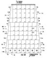
- FIG. 1B is a top view of an example of the reconfigurable floorboard system 102 with a plurality of floorboards 112 installed on the floor grid structure 100 ( Figure 1A ) in accordance with an embodiment of the present disclosure.
- each of the floorboards may include a substantially trapezoid shaped plate as illustrated in Figure 1B .
- the plurality of floorboards 112 may include a plurality of sets of tapered floorboards 114.
- Each tapered floorboard 114 may have a predetermined tapered form for insertion in the floorboard system 102 of the aircraft 104 next to a tapered interior portion 116 of the fuselage 108 of the aircraft 104.
- the tapered interior portion 116 of the fuselage 108 may also have a selected curvature.
- An outboard side of each tapered floorboard 114 may then have a chosen curvature to substantially match the selected curvature of the interior portion 116 of the fuselage 108.
- the outboard side of each tapered floorboard 114 may be formed to substantially match or correspond to the interior portion 116 of the fuselage so that the outboard side of each tapered floorboard 114 may abut or contact the interior 116 of the fuselage 108 to prevent FOD from getting to an area underneath the floorboards 112 and to provide stability of the floorboards 112.
- each complete set of tapered floorboards 114 may include three different types of tapered floorboards 114a, 114b and 114c.
- the different types of tapered floorboards 114a, 114b and 114c may respectively each be substantially identical and may have the same dimensions and other structural features in each set of floorboards 114 so that the respective types of floorboards 114a-114c may be interchangeable with the same type floorboard 114a-114c and the floorboards may be dynamically reconfigured, for example, in different aircraft.
- the fuselage 108 only one or two tapered floorboards 114 may be used.
- a forward section 120 of the fuselage 108 in the example of Figure 1B only uses tapered floorboard types 114b and 114c.
- the plurality of floorboards 112 may also include a set of substantially square shaped floorboards 122.
- the floorboards 122 may be another shape, such as rectangular.
- the set of substantially square shaped floorboards 122 may be for insertion in the floorboard system 102 between the sets of tapered floorboards 114 which are installed next to opposite sides of the fuselage 108.
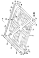
- Figure 3A is a bottom detailed perspective view of an example of a floorboard 300 for use in a reconfigurable floorboard system, such as the floorboard system 102 in Figure 1B in accordance with an embodiment of the present disclosure.
- Figure 3B is a top detailed perspective view of the exemplary floorboard 300 of Figure 3A in accordance with an embodiment of the present disclosure.
- the floorboard 300 may be used for floorboards 122 in Figure 2B .
- the tapered floorboards 122 in Figure 2B would also include similar features to those of floorboard 300 but may not have an interlocking feature formed on each side of the floorboard.
- the side of the tapered floorboard 114a-114c that contacts the fuselage 108 may not include an interlocking feature.
- the floorboard 300 may include a substantially trapezoid shaped plate 302. As previously described, the floorboard 300 or plate 302 may be tapered to substantially correspond to an interior portion of a vehicle or fuselage of an aircraft. The floorboard 300 or plate 302 may also be substantially square or rectangular for insertion into a reconfigurable floor system, such as system 102 in Figure 1B .
- the floorboard 300 may also include an interlocking feature 304 formed proximate an edge of at least three sides of the plate 302 for interlocking with adjacent floorboards.
- Each interlocking feature 304 may be formed to interlock with a mating interlocking feature 304 formed at an edge of a side of at least one adjacent floorboard.
- the floorboard 300 may also include a notch 306 formed on an underside 308 ( Figure 3A ) of the plate 302 proximate each corner of the plate 302.
- the notch 306 is adapted to contact a member 400 of a floor grid, such as floor grid 100 in Figure 1 to prevent lateral movement of the floorboard 300 or 114 or 122 in Figure 1B .
- the notch 306 is also located proximate each corner of the plate 302 or floorboard 300 to provide stability when the floorboard bears weight to prevent any tipping or movement of the floorboard 300.
- Figure 4 is a side cross-sectional view of a portion of the floorboard system 102 of Figure 1B taken along lines 4-4.
- the member 400 of the floor grid may be the floor track 110 in Figure 1A disposed on the floor beam 106.
- the notch 306 may include a right-angled portion 310 formed by a horizontal surface 312 for contacting a top portion of the floor grid member 400 and a vertical surface 314 for contacting a side of the floor grid member 400 to prevent lateral movement of the floorboard 300.
- a pad 307 ( Figure 3A ) may also be disposed in the right-angled portion 310 of the notch 306 to further provide stability of the floorboard.
- the interlocking feature 304 may include a first interlocking feature 316 on each of two adjacent sides 318a and 318b of the floorboard 300 as best shown in Figure 3A , and a second interlocking feature 320 on each of two other adjacent sides 322a and 322b of the floorboard 300 as best shown in Figure 3B .
- Each of the first interlocking features 316 is adapted to matingly interlock with the second interlocking feature 320 and vice versa on respective adjacent floorboards.
- Each first interlocking feature 316 may include a lip 324 integrally extending laterally from an upper surface 326 of the plate 302 substantially completely along each side 318a and 318b of the plate 302 ( Figure 3A ).
- each first interlocking feature 316 may also include a projection 328 extending downward from the lip 324 at an edge of the lip 324.
- Each first interlocking feature 316 may also include a groove 330 formed in an underside 332 of the lip 324 by the projection 328 and a side edge 334 of the plate 302 or floorboard 300a as best shown in Figure 4 .
- Each second interlocking feature 320 may include a projection 336 extending upwardly from the edge of an adjacent floorboard 300b ( Figure 4 ).
- Each second interlocking feature 320 may also include a groove 338 formed in an upper surface 326 of the floorboard 300b or plate 302. One side of groove 338 may be formed by the projection 336 of the second interlocking feature 320.
- the groove 338 of the second interlocking feature 320 is adapted to matingly receive the projection 328 of the first interlocking feature 316 of the adjacent floorboard 300a and the groove 330 of the first interlocking feature 316 is adapted to matingly receive the projection 336 of the second interlocking feature 320 of the other adjacent floorboard 330b to interlock the adjacent floorboards 300a and 300b.
- first interlocking feature 316 and the second interlocking feature 320 each matingly receive the other as just described, either of the interlocking features 316 and 320 may be referred to herein as a mating interlocking feature or similar terminology.
- the first and second interlocking features 316 and 320 overlap one another and provide a seal when interlocked to prevent any FOD from falling in an area 402 beneath the floorboards 300a and 300b.
- the overlapping structure of the interlocking features 316 and 320 provides stability and eliminates the laborious need to tape the joints between the floorboards.
- Each floorboard 300 may also include a handle 340 integrally formed in the floorboard 300.
- the handle 340 may include an enclosed interior 342 except for an opening 344 in the upper surface 326 of the floorboard 300 for insertion of a user's fingers to grip the floorboard 300.
- the interior 342 of the handle 340 is enclosed and not open to the area 402 underneath the floorboard 300 to prevent any FOD falling into the area 402 underneath the floorboards 300a and 300b.
- Each floorboard 300 may also include non-slip strips or a similar feature on the upper surface 326 of the floorboard 300 to improve footing and minimize slippage by personnel.
- Each floorboard 300 may also include a predetermined reinforcing structure 346 ( Figure 3A ).
- the reinforcing structure 346 may be integrally formed on an underside 308 of the floorboard 300.
- the floorboard 300 may be made from a suitable plastic, polyvinylchloride (PVC), injection moldable plastic or other material that may be lightweight yet have sufficient strength to withstand any expected loads during use or construction of the vehicle or structure.
- PVC polyvinylchloride
- injection moldable plastic or other material that may be lightweight yet have sufficient strength to withstand any expected loads during use or construction of the vehicle or structure.
- Figures 5A and 5B are an example of a moveable cart 500 for storing multiple floorboards 300 and efficiently moving the floorboards 300 from one location to another in accordance with an embodiment of the present disclosure.
- Figure 5A is an illustration of the cart 500 unloaded or without any floorboards
- Figure 5B is an illustration of the cart 500 at least partially filled with floorboards 300.
- the cart 500 may include a plurality of vertically spaced ledges 502 or racks adapted to receive the horizontal surface 312 of the notch 306 ( Figure 4 ).
- Each of the ledges 502 or racks are at a predetermined spacing from one another to accommodate a second floorboard 300 being stacked on the first floorboard 300 on each ledge 502 with the second floorboard 300 being placed upside down on the first floorboard 300 or with the upper surfaces 326 ( Figure 4 ) of the two floorboards 300 facing each other in the cart 500.
- the cart 500 may also include a side rack 504 for storing tapered floorboards, such as tapered floorboards 114 similar to that illustrated in Figure 1B or floorboards with other shapes which may not conveniently fit in the racks or ledges 502.
- Caster wheels 506 or similar wheels may also be mounted to the cart 500 for rolling the cart 500 between locations and for rolling the cart 500 within an aircraft or structure under construction to facilitate placement of the floorboards 500, reconfiguration or removal of the floorboards 300.
- FIG 6 is a flow chart of an example of a method 600 for installing a reconfigurable floorboard system in accordance with an embodiment of the present disclosure.
- the reconfigurable floorboard system may be the same as the system 102 in Figures 1A and 1B .
- a floor grid may be formed or constructed on an interior of a vehicle or structure.
- a plurality of floorboards may be interlocked on the floor grid.
- Each floorboard may be interlocked by receiving by an interlocking feature formed at an edge of a side of the floorboard, a mating interlocking feature formed at an edge of a side of at least one adjacent floorboard.
- each floorboard may be interlocked by receiving a projection of at least one adjacent floorboard in a groove of the floorboard. The groove may extend substantially completely along the side of the floorboard at the edge of the floorboard similar to that described herein.
- a plurality of sets of tapered floorboards may be interlocked in the floorboard system, such as for example a floorboard system for an aircraft or similar structure.
- Each tapered floorboard may include a predetermined tapered form for interlocking in the floorboard system next to a tapered interior portion of a fuselage of the aircraft or other structure.
- a set of substantially square shaped floorboards may be interlocked in the floorboard system between the sets of tapered floorboards.
- a notch formed on an underside of the floorboard proximate each corner of the floorboard may abut or contact a member of the floor grid to prevent lateral movement of the floorboard in the floorboard system and to provide stability for bearing weight.
Landscapes
- Engineering & Computer Science (AREA)
- Aviation & Aerospace Engineering (AREA)
- Manufacturing & Machinery (AREA)
- Mechanical Engineering (AREA)
- Transportation (AREA)
- Floor Finish (AREA)
- Packaging Of Machine Parts And Wound Products (AREA)
Abstract

Description
- The present disclosure relates to aircraft, aerospace vehicles, other vehicles and other structures, and more particularly to dynamic optimized reconfigurable floorboard system for aircraft, other vehicles or other structures.
- During the fabrication of a vehicle, such as an aircraft or other aerospace vehicle, a floor including a plurality of floorboards may be installed to facility construction of the vehicle or aircraft. Mechanics have to maneuver over a passenger floor grid in the case of a passenger airliner to load the floorboards into the floor grid. The floorboards are then taped together to prevent movement and to prevent foreign object debris (FOD) from falling through any spaces between the floorboards. Taping the boards together requires a significant amount of labor and time. Maintenance is also required to make sure the boards continue to form a barrier to FOD. Additionally, boards often have to be removed to install components of the aircraft, such as galley support hose components and other equipment. This requires removal of the tape from the effected boards and re-taping when the board is reinstalled. The boards may also sit on top of fillers at some locations which may cause the boards to be unstable. The boards can also be cumbersome and difficult to handle requiring multiple mechanics for proper placement and installation. There is need for a reconfigurable floorboard system that can be easily and efficiently installed, protects from FOD and permits floorboards to be easily and efficiently removed and replaced.
- In accordance with an embodiment, a floorboard for a reconfigurable floorboard system may include a substantially trapezoid shaped plate. An interlocking feature may be formed proximate an edge of at least three sides of the plate for interlocking with adjacent floorboards. Each interlocking feature may be formed to interlock with a mating interlocking feature formed at an edge of a side of at least one adjacent floorboard. A notch may be formed on an underside of the plate proximate each corner of the plate to contact a member of a floor grid to prevent movement of the floorboard and to provide stability of the floorboard when it bears weight.
- In accordance with an embodiment, a reconfigurable floorboard system may include a floor grid structure. A plurality of floorboards may be disposed on the floor grid structure. Each floorboard may include a substantially trapezoid shaped plate. An interlocking feature may be formed proximate to an edge of at least three sides of the plate for interlocking with adjacent floorboards. Each interlocking feature may be formed to interlock with a mating interlocking feature formed at an edge of a side of at least one adjacent floorboard. A notch may be formed on an underside of the plate proximate each corner of the plate to contact a member of the floor grid structure to prevent lateral movement of the floorboard and to provide stability of the floorboard when it bears weight.
- In accordance with another embodiment, a method for installing a reconfigurable floorboard system may include interlocking each of a plurality of floorboards on a floor grid. Interlocking each floorboard may include receiving by an interlocking feature formed at an edge of a side of the floorboard, a mating interlocking feature formed at an edge of a side of at least one adjacent floorboard. The method may also include abutting a notch formed on an underside of the floorboard proximate each corner of the floorboard to a member of the floor grid to prevent lateral movement of the floorboard.
- In accordance with another embodiment, there is disclosed a floorboard for a reconfigurable floorboard system, comprising: a substantially trapezoid shaped plate; an interlocking feature formed proximate an edge of at least three sides of the plate for interlocking with adjacent floorboards, each interlocking feature being formed to interlock with a mating interlocking feature formed at an edge of a side of at least one adjacent floorboard; and a notch formed on an underside of the plate proximate each corner of the plate to contact a member of a floor grid to prevent movement of the floorboard; wherein the interlocking feature comprises a groove extending substantially completely along the side of the plate proximate to the edge of the plate to matingly receive a projection of the mating interlocking feature formed at the edge of the adjacent floorboard; wherein the interlocking feature comprises a lip extending from an upper surface of the plate, the lip comprising: a projection extending downward from the lip at an edge of the lip; and a groove formed in an underside of the lip by the projection and a side edge of the plate, the groove being adapted to matingly receive a projection extending upwardly from an edge of the adjacent floorboard and the projection extending downwardly from the lip being adapted to be matingly received by a groove formed in an upper surface of the adjacent floorboard; wherein the interlocking feature comprises: a projection extending upwardly from the edge of the floorboard; and a groove formed in an upper surface of the floorboard adjacent the projection to matingly receive a projection extending downward from a edge of a lip extending from an upper surface of the adjacent floorboard, the projection extending upwardly from the floorboard being adapted to be matingly received in a groove formed in an underside of the lip by the projection extending downward from the lip of the adjacent floorboard and a side edge of the adjacent floorboard; wherein the plate is substantially square shaped and wherein the interlocking feature comprises a first interlocking feature on each of two adjacent sides of the floorboard and a second interlocking feature on each of two other adjacent sides of the floorboard, wherein each of the first interlocking features is adapted to matingly interlock with the second interlocking feature on a respective adjacent floorboard; wherein the first interlocking feature comprises: a lip integrally extending laterally from an upper surface of the plate substantially completely along the side of the plate; a projection extending downward from the lip at an edge of the lip; and a groove formed in an underside of the lip by the projection and a side edge of the plate; wherein the second interlocking feature comprises: a projection extending upwardly from the edge of the floorboard; and a groove formed in the upper surface of the floorboard, one side of groove being formed by the projection of the second interlocking feature, the groove of the second interlocking feature being adapted to matingly receive a projection of a first interlocking feature of the adjacent floorboard and the groove of the first interlocking feature being adapted to matingly receive a projection of a second interlocking feature of another adjacent floorboard to interlock the floorboards; and further comprising a handle integrally formed in the floorboard, wherein the handle comprises an enclosed interior except for an opening in an upper surface of the floorboard for insertion of a user's fingers to grip the floorboard; wherein the floorboard comprises a predetermined tapered form shaped for insertion in the floorboard system of an aircraft next to a tapered interior portion of a fuselage of the aircraft.
- Other aspects and features of the present disclosure, as defined solely by the claims, will become apparent to those ordinarily skilled in the art upon review of the following non-limited detailed description of the disclosure in conjunction with the accompanying figures.
- The following detailed description of embodiments refers to the accompanying drawings, which illustrate specific embodiments of the disclosure. Other embodiments having different structures and operations do not depart from the scope of the present disclosure.
-
Figure 1A is a top view of an example of a floor grid for a reconfigurable floorboard system in accordance with an embodiment of the present disclosure. -
Figure 1B is a top view of an example of the reconfigurable floorboard system with the floorboards installed on the floor grid in accordance with an embodiment of the present disclosure. -
Figure 2 is a detailed cross-section of an example of a floor track of a floor grid in accordance with an embodiment of the present disclosure. -
Figure 3A is a bottom detailed perspective view of a floorboard for use in a reconfigurable floorboard system in accordance with an embodiment of the present disclosure. -
Figure 3B is a top detailed perspective view of the exemplary floorboard ofFigure 3A in accordance with an embodiment of the present disclosure. -
Figure 4 is a side cross-sectional view of a portion of the floorboard system ofFigure 1B taken along lines 4-4. -
Figures 5A and 5B are an example of a moveable cart for storing the floorboards and moving the floorboards from one location to another in accordance with an embodiment of the present disclosure without any floorboards. -
Figure 6 is a flow chart of an example of a method for installing a reconfigurable floorboard system in accordance with an embodiment of the present disclosure. - The following detailed description of embodiments refers to the accompanying drawings, which illustrate specific embodiments of the disclosure. Other embodiments having different structures and operations do not depart from the scope of the present disclosure. Like reference numerals may refer to the same element or component in the different drawings.
-
Figure 1A is a top view of an example of afloor grid structure 100 for areconfigurable floorboard system 102 in accordance with an embodiment of the present disclosure. Thereconfigurable floorboard system 102 will be described herein with regard to use in anaircraft 104, although thefloorboard system 102 described herein may be adapted for use in any vehicle or other structure. The floor grid structure orfloor grid 100 may be formed or constructed on an interior of a vehicle or other structure. Thefloor grid 100 may include a plurality offloor beams 106. Thefloor beams 106 may extend laterally across theaircraft 104 between opposite sides of afuselage 108 of theaircraft 104. Thefloor grid 100 may also include a plurality offloor tracks 110. Thefloor tracks 110 may extend substantially orthogonally to thefloor beams 106. Thefloor tracks 110 may be attached to thefloor beams 106 by suitable fasteners or by another mechanism. - Referring also to
Figure 2, Figure 2 is a detailed cross-section of an example of afloor track 200 of afloor grid structure 202 in accordance with an embodiment of the present disclosure. Thefloor grid 202 andfloor track 200 may be the same as thefloor grid 100 andfloor track 110 ofFigure 1 with the cross-section taken along lines 2-2. Thefloor track 200 may be substantially pi (π) shaped including a pair ofvertical members top member 208 joining the twovertical members lower flange 210 may extend perpendicular from a lower end of eachvertical member intermediate flange 212 may extend perpendicular from eachvertical member top member 208 and eachlower flange 210. Theintermediate flanges 212 may be disposed on afloor beam 214 of thefloor grid 202. Thefloor track 200 may be attached to thefloor beam 214 by fastening theintermediate flanges 212 to thefloor beam 214. - Referring now to
Figure 1B, Figure 1B is a top view of an example of thereconfigurable floorboard system 102 with a plurality offloorboards 112 installed on the floor grid structure 100 (Figure 1A ) in accordance with an embodiment of the present disclosure. As described in more detail herein, each of the floorboards may include a substantially trapezoid shaped plate as illustrated inFigure 1B . In accordance with an embodiment, particularly for anaircraft 104, the plurality offloorboards 112 may include a plurality of sets oftapered floorboards 114. Eachtapered floorboard 114 may have a predetermined tapered form for insertion in thefloorboard system 102 of theaircraft 104 next to a taperedinterior portion 116 of thefuselage 108 of theaircraft 104. The taperedinterior portion 116 of thefuselage 108 may also have a selected curvature. An outboard side of eachtapered floorboard 114 may then have a chosen curvature to substantially match the selected curvature of theinterior portion 116 of thefuselage 108. Accordingly, the outboard side of eachtapered floorboard 114 may be formed to substantially match or correspond to theinterior portion 116 of the fuselage so that the outboard side of eachtapered floorboard 114 may abut or contact theinterior 116 of thefuselage 108 to prevent FOD from getting to an area underneath thefloorboards 112 and to provide stability of thefloorboards 112. - In accordance with an embodiment, each complete set of tapered
floorboards 114 may include three different types of taperedfloorboards floorboards floorboards 114 so that the respective types offloorboards 114a-114c may be interchangeable with thesame type floorboard 114a-114c and the floorboards may be dynamically reconfigured, for example, in different aircraft. Along some portions of thefuselage 108 only one or two taperedfloorboards 114 may be used. For example, aforward section 120 of thefuselage 108 in the example ofFigure 1B only uses taperedfloorboard types - The plurality of
floorboards 112 may also include a set of substantially square shapedfloorboards 122. In another embodiment, thefloorboards 122 may be another shape, such as rectangular. The set of substantially square shapedfloorboards 122 may be for insertion in thefloorboard system 102 between the sets of taperedfloorboards 114 which are installed next to opposite sides of thefuselage 108. - Referring now to
Figures 3A and3B ,Figure 3A is a bottom detailed perspective view of an example of afloorboard 300 for use in a reconfigurable floorboard system, such as thefloorboard system 102 inFigure 1B in accordance with an embodiment of the present disclosure.Figure 3B is a top detailed perspective view of theexemplary floorboard 300 ofFigure 3A in accordance with an embodiment of the present disclosure. Thefloorboard 300 may be used forfloorboards 122 inFigure 2B . The taperedfloorboards 122 inFigure 2B would also include similar features to those offloorboard 300 but may not have an interlocking feature formed on each side of the floorboard. For example, the side of the taperedfloorboard 114a-114c that contacts thefuselage 108 may not include an interlocking feature. - The
floorboard 300 may include a substantially trapezoid shapedplate 302. As previously described, thefloorboard 300 orplate 302 may be tapered to substantially correspond to an interior portion of a vehicle or fuselage of an aircraft. Thefloorboard 300 orplate 302 may also be substantially square or rectangular for insertion into a reconfigurable floor system, such assystem 102 inFigure 1B . - The
floorboard 300 may also include aninterlocking feature 304 formed proximate an edge of at least three sides of theplate 302 for interlocking with adjacent floorboards. Each interlockingfeature 304 may be formed to interlock with amating interlocking feature 304 formed at an edge of a side of at least one adjacent floorboard. - The
floorboard 300 may also include anotch 306 formed on an underside 308 (Figure 3A ) of theplate 302 proximate each corner of theplate 302. As best illustrated inFigure 4 , thenotch 306 is adapted to contact amember 400 of a floor grid, such asfloor grid 100 inFigure 1 to prevent lateral movement of thefloorboard Figure 1B . Thenotch 306 is also located proximate each corner of theplate 302 orfloorboard 300 to provide stability when the floorboard bears weight to prevent any tipping or movement of thefloorboard 300.Figure 4 is a side cross-sectional view of a portion of thefloorboard system 102 ofFigure 1B taken along lines 4-4. Themember 400 of the floor grid may be thefloor track 110 inFigure 1A disposed on thefloor beam 106. - The
notch 306 may include a right-angled portion 310 formed by ahorizontal surface 312 for contacting a top portion of thefloor grid member 400 and avertical surface 314 for contacting a side of thefloor grid member 400 to prevent lateral movement of thefloorboard 300. A pad 307 (Figure 3A ) may also be disposed in the right-angled portion 310 of thenotch 306 to further provide stability of the floorboard. - The interlocking
feature 304 may include afirst interlocking feature 316 on each of twoadjacent sides floorboard 300 as best shown inFigure 3A , and asecond interlocking feature 320 on each of two otheradjacent sides floorboard 300 as best shown inFigure 3B . Each of the first interlocking features 316 is adapted to matingly interlock with thesecond interlocking feature 320 and vice versa on respective adjacent floorboards. - Each
first interlocking feature 316 may include alip 324 integrally extending laterally from anupper surface 326 of theplate 302 substantially completely along eachside Figure 3A ). Referring also toFigure 4 , eachfirst interlocking feature 316 may also include aprojection 328 extending downward from thelip 324 at an edge of thelip 324. Eachfirst interlocking feature 316 may also include agroove 330 formed in anunderside 332 of thelip 324 by theprojection 328 and aside edge 334 of theplate 302 orfloorboard 300a as best shown inFigure 4 . - Each
second interlocking feature 320 may include aprojection 336 extending upwardly from the edge of anadjacent floorboard 300b (Figure 4 ). Eachsecond interlocking feature 320 may also include agroove 338 formed in anupper surface 326 of thefloorboard 300b orplate 302. One side ofgroove 338 may be formed by theprojection 336 of thesecond interlocking feature 320. Thegroove 338 of thesecond interlocking feature 320 is adapted to matingly receive theprojection 328 of thefirst interlocking feature 316 of theadjacent floorboard 300a and thegroove 330 of thefirst interlocking feature 316 is adapted to matingly receive theprojection 336 of thesecond interlocking feature 320 of the other adjacent floorboard 330b to interlock theadjacent floorboards first interlocking feature 316 and thesecond interlocking feature 320 each matingly receive the other as just described, either of the interlocking features 316 and 320 may be referred to herein as a mating interlocking feature or similar terminology. As illustrated inFigure 4 , the first and second interlocking features 316 and 320 overlap one another and provide a seal when interlocked to prevent any FOD from falling in anarea 402 beneath thefloorboards - Each
floorboard 300 may also include ahandle 340 integrally formed in thefloorboard 300. Thehandle 340 may include anenclosed interior 342 except for anopening 344 in theupper surface 326 of thefloorboard 300 for insertion of a user's fingers to grip thefloorboard 300. Theinterior 342 of thehandle 340 is enclosed and not open to thearea 402 underneath thefloorboard 300 to prevent any FOD falling into thearea 402 underneath thefloorboards floorboard 300 may also include non-slip strips or a similar feature on theupper surface 326 of thefloorboard 300 to improve footing and minimize slippage by personnel. - Each
floorboard 300 may also include a predetermined reinforcing structure 346 (Figure 3A ). The reinforcingstructure 346 may be integrally formed on anunderside 308 of thefloorboard 300. Thefloorboard 300 may be made from a suitable plastic, polyvinylchloride (PVC), injection moldable plastic or other material that may be lightweight yet have sufficient strength to withstand any expected loads during use or construction of the vehicle or structure. -
Figures 5A and 5B are an example of amoveable cart 500 for storingmultiple floorboards 300 and efficiently moving thefloorboards 300 from one location to another in accordance with an embodiment of the present disclosure.Figure 5A is an illustration of thecart 500 unloaded or without any floorboards andFigure 5B is an illustration of thecart 500 at least partially filled withfloorboards 300. Thecart 500 may include a plurality of vertically spacedledges 502 or racks adapted to receive thehorizontal surface 312 of the notch 306 (Figure 4 ). Each of theledges 502 or racks are at a predetermined spacing from one another to accommodate asecond floorboard 300 being stacked on thefirst floorboard 300 on eachledge 502 with thesecond floorboard 300 being placed upside down on thefirst floorboard 300 or with the upper surfaces 326 (Figure 4 ) of the twofloorboards 300 facing each other in thecart 500. - The
cart 500 may also include aside rack 504 for storing tapered floorboards, such as taperedfloorboards 114 similar to that illustrated inFigure 1B or floorboards with other shapes which may not conveniently fit in the racks orledges 502.Caster wheels 506 or similar wheels may also be mounted to thecart 500 for rolling thecart 500 between locations and for rolling thecart 500 within an aircraft or structure under construction to facilitate placement of thefloorboards 500, reconfiguration or removal of thefloorboards 300. -
Figure 6 is a flow chart of an example of amethod 600 for installing a reconfigurable floorboard system in accordance with an embodiment of the present disclosure. The reconfigurable floorboard system may be the same as thesystem 102 inFigures 1A and1B . Inblock 602, a floor grid may be formed or constructed on an interior of a vehicle or structure. - In
block 604, a plurality of floorboards may be interlocked on the floor grid. Each floorboard may be interlocked by receiving by an interlocking feature formed at an edge of a side of the floorboard, a mating interlocking feature formed at an edge of a side of at least one adjacent floorboard. In an embodiment, each floorboard may be interlocked by receiving a projection of at least one adjacent floorboard in a groove of the floorboard. The groove may extend substantially completely along the side of the floorboard at the edge of the floorboard similar to that described herein. - In
block 606, a plurality of sets of tapered floorboards may be interlocked in the floorboard system, such as for example a floorboard system for an aircraft or similar structure. Each tapered floorboard may include a predetermined tapered form for interlocking in the floorboard system next to a tapered interior portion of a fuselage of the aircraft or other structure. - In
block 608, a set of substantially square shaped floorboards may be interlocked in the floorboard system between the sets of tapered floorboards. Inblock 610, a notch formed on an underside of the floorboard proximate each corner of the floorboard may abut or contact a member of the floor grid to prevent lateral movement of the floorboard in the floorboard system and to provide stability for bearing weight. - The terminology used herein is for the purpose of describing particular embodiments only and is not intended to be limiting of the disclosure. As used herein, the singular forms "a", "an" and "the" are intended to include the plural forms as well, unless the context clearly indicates otherwise. It will be further understood that the terms "comprises" and/or "comprising," when used in this specification, specify the presence of stated features, integers, steps, operations, elements, and/or components, but do not preclude the presence or addition of one or more other features, integers, steps, operations, elements, components, and/or groups thereof.
- Although specific embodiments have been illustrated and described herein, those of ordinary skill in the art appreciate that any arrangement which is calculated to achieve the same purpose may be substituted for the specific embodiments shown and that the embodiments herein have other applications in other environments. This application is intended to cover any adaptations or variations of the present disclosure. The following claims are in no way intended to limit the scope of the disclosure to the specific embodiments described herein.
Claims (12)
- A reconfigurable floorboard system, comprising:a floor grid structure;a plurality of floorboards disposed on the grid structure, each floorboard comprising:a substantially trapezoid shaped plate;an interlocking feature formed proximate an edge of at least three sides of the plate for interlocking with adjacent floorboards, each interlocking feature being formed to interlock with a mating interlocking feature formed at an edge of a side of at least one adjacent floorboard; anda notch formed on an underside of the plate proximate each corner of the plate to contact a member of the floor grid structure to prevent lateral movement of the floorboard.
- The floorboard system of claim 1, wherein the interlocking feature comprises a groove extending substantially completely along the side of the plate proximate to the edge of the plate to matingly receive a projection of the mating interlocking feature formed at the edge of the adjacent floorboard.
- The floorboard system of claim 1, wherein the interlocking feature comprises a first interlocking feature on each of two adjacent sides of the floorboard and a second interlocking feature on each of two other adjacent sides of the floorboard, wherein each of the first interlocking features is adapted to matingly interlock with the second interlocking feature on a respective adjacent floorboard.
- The floorboard system of claim 3, wherein the first interlocking feature comprises:a lip integrally extending laterally from an upper surface of the plate substantially completely along the side of the plate;a projection extending downward from the lip at an edge of the lip; anda groove formed in an underside of the lip by the projection and a side edge of the plate;wherein the second interlocking feature comprises:a projection extending upwardly from the edge of the floorboard; anda groove formed in the upper surface of the floorboard, one side of groove being formed by the projection of the second interlocking feature, the groove of the second interlocking feature being adapted to matingly receive a projection of a first interlocking feature of the adjacent floorboard and the groove of the first interlocking feature being adapted to matingly receive a projection of a second interlocking feature of another adjacent floorboard to interlock the floorboards.
- The floorboard system of claim 1, wherein the plurality of floorboards comprises:a plurality of sets of tapered floorboards, each tapered floorboard having a predetermined tapered form for insertion in the floorboard system of an aircraft next to a tapered interior portion of a fuselage of the aircraft; anda set of substantially square shaped floorboards for insertion in the floorboard system between the sets of tapered floorboards next to opposite interior sides of the fuselage.
- The floorboard system of claim 1, further comprising a handle integrally formed in the floorboard, wherein the handle comprises an enclosed interior except for an opening in an upper surface of the floorboard for insertion of a user's fingers to grip the floorboard, wherein the handle permits reconfiguration of the floorboard system and removal of a selected floorboard for access to an area underneath the floorboard.
- The floorboard system of claim 1, wherein the plurality of floorboards are adapted to be stored on a moveable cart.
- A method for installing a reconfigurable floorboard system, comprising:interlocking each of a plurality of floorboards on a floor grid, wherein interlocking each floorboard comprises receiving by an interlocking feature formed at an edge of a side of the floorboard, a mating interlocking feature formed at an edge of a side of at least one adjacent floorboard; andabutting a notch formed on an underside of the floorboard proximate each corner of the floorboard to a member of the floor grid to prevent lateral movement of the floorboard.
- The method of claim 8, wherein interlocking each floorboard comprises receiving a projection of the at least one adjacent floorboard in a groove of the floorboard, the groove extending substantially completely along the side of the floorboard at the edge of the floorboard.
- The method of claim 8, wherein the floorboard is substantially square shaped and wherein the interlocking feature comprises a first interlocking feature on each of two adjacent sides of the floorboard and a second interlocking feature on each of two other adjacent sides of the floorboard, interlocking each floorboard comprises matingly interlocking each of the first interlocking features with the second interlocking feature on the at least one adjacent floorboard.
- The method of claim 10, wherein the first interlocking feature comprises:a lip integrally extending laterally from an upper surface of the floorboard substantially completely along the side of the floorboard;a projection extending downward from the lip at an edge of the lip; anda groove formed in an underside of the lip by the projection and a side edge of the floorboard;wherein the second interlocking feature comprises:a projection extending upwardly from the edge of the floorboard; anda groove formed in the upper surface of the floorboard, one side of groove being formed by the projection of the second interlocking feature,wherein interlocking the plurality of floorboards comprises:matingly receiving by the groove of the second interlocking feature a projection of a first interlocking feature of the at least one adjacent floorboard; andmatingly receiving by the groove of the first interlocking feature a projection of a second interlocking feature of another adjacent floorboard to interlock the floorboards.
- The method of claim 8, wherein the reconfigurable floorboard system is installed in an aircraft and wherein interlocking the plurality of floorboards comprises:interlocking a plurality of sets of tapered floorboards, each tapered floorboard having a predetermined tapered form for interlocking in the floorboard system of the aircraft next to a tapered interior portion of a fuselage of the aircraft; andinterlocking a set of substantially square shaped floorboards for interlocking in the floorboard system between the sets of tapered floorboards next to opposite interior sides of the fuselage.
Applications Claiming Priority (1)
| Application Number | Priority Date | Filing Date | Title |
|---|---|---|---|
| US13/105,432 US9016625B2 (en) | 2011-05-11 | 2011-05-11 | Reconfigurable floorboard system |
Publications (3)
| Publication Number | Publication Date |
|---|---|
| EP2522573A2 true EP2522573A2 (en) | 2012-11-14 |
| EP2522573A3 EP2522573A3 (en) | 2015-06-24 |
| EP2522573B1 EP2522573B1 (en) | 2020-01-01 |
Family
ID=45952916
Family Applications (1)
| Application Number | Title | Priority Date | Filing Date |
|---|---|---|---|
| EP12162003.3A Active EP2522573B1 (en) | 2011-05-11 | 2012-03-29 | Reconfigurable floorboard system |
Country Status (2)
| Country | Link |
|---|---|
| US (1) | US9016625B2 (en) |
| EP (1) | EP2522573B1 (en) |
Cited By (2)
| Publication number | Priority date | Publication date | Assignee | Title |
|---|---|---|---|---|
| EP2889222A1 (en) * | 2013-12-31 | 2015-07-01 | Airbus Operations (S.A.S) | Temporary floor for an aircraft cabin, used during the construction of the aircraft, and slab making up said floor |
| EP3663053A1 (en) * | 2016-08-24 | 2020-06-10 | The Boeing Company | Method for installing temporary floor boards into a fuselage of an aircraft |
Families Citing this family (5)
| Publication number | Priority date | Publication date | Assignee | Title |
|---|---|---|---|---|
| US9016252B2 (en) | 2008-07-22 | 2015-04-28 | Eaton Corporation | System to diagnose variable valve actuation malfunctions by monitoring fluid pressure in a hydraulic lash adjuster gallery |
| US10501943B1 (en) * | 2016-02-19 | 2019-12-10 | Custom Finish Wood Flooring Llc | Systems and methods for installing flooring |
| DE102018108950B3 (en) * | 2018-03-07 | 2019-03-21 | Telair International Gmbh | Cargo deck of an aircraft and method of making a floor module |
| US11428015B2 (en) * | 2020-09-03 | 2022-08-30 | Wearwell, Llc | Modular platform system and method of assembly |
| CN113450931B (en) * | 2021-04-12 | 2022-10-28 | 中广核研究院有限公司 | Fuel assembly positioning grid, fuel assembly and reactor core |
Family Cites Families (24)
| Publication number | Priority date | Publication date | Assignee | Title |
|---|---|---|---|---|
| US3279134A (en) * | 1963-05-28 | 1966-10-18 | Electronic Flooring Systems In | Elevated floor construction |
| FR1554826A (en) * | 1967-12-05 | 1969-01-24 | ||
| US3696578A (en) * | 1970-03-06 | 1972-10-10 | Liskey Aluminum | Floor panel for an elevated floor assembly |
| US4000870A (en) * | 1975-09-08 | 1977-01-04 | Western Gear Corporation | Modular system for quick conversion of aircraft passenger compartments to cargo baggage/compartments |
| US4574555A (en) * | 1983-10-19 | 1986-03-11 | Donn Incorporated | Access floor panel with edge trim |
| US4676036A (en) * | 1985-05-01 | 1987-06-30 | Airtite, Inc. | Integrated raised flooring system |
| FR2781513B1 (en) * | 1998-07-22 | 2004-07-30 | Polystar | TILE-TYPE SURFACE ELEMENT, FLOOR PANEL, WALL, ROOF FOR EXAMPLE |
| FR2835553B1 (en) * | 2002-02-01 | 2004-10-01 | Pierre Belbenoit | DEVICE FOR POSITIONING AND LOCKING THE SLABS OF A RAISED FLOOR ON VERTICAL SUPPORTS |
| US6554225B1 (en) | 2002-06-14 | 2003-04-29 | The Boeing Company | Commercial aircraft low cost, lightweight floor design |
| WO2005012085A1 (en) * | 2003-07-18 | 2005-02-10 | Telair International Gmbh | Floor for an aircraft cargo compartment an a method for the assembly thereof |
| US20050016098A1 (en) * | 2003-07-22 | 2005-01-27 | Hahn Lindsey R. | Attic deck system |
| FR2872781B1 (en) | 2004-07-08 | 2007-10-05 | Airbus France Sas | FLOOR FOR AIRCRAFT |
| FR2872780B1 (en) | 2004-07-08 | 2006-11-17 | Airbus France Sas | FLOOR FOR AIRCRAFT |
| DE102006007469A1 (en) | 2006-02-17 | 2007-08-30 | Airbus Deutschland Gmbh | Floor structure for use in e.g. large-capacity passenger aircraft, has number of seat rails and floor panel with set of through-holes, where interior equipment components of aircraft are locked into place on seat rails via holes |
| US8360362B2 (en) * | 2006-02-21 | 2013-01-29 | The Boeing Company | Aircraft floor and method of assembly |
| US7490443B1 (en) * | 2006-03-01 | 2009-02-17 | Bike Track, Inc. | Modular flooring system |
| ES1062734Y (en) * | 2006-04-17 | 2006-10-16 | Golden Decking S L | PERFECTED PLATE FOR SOIL CONFIGURATION |
| US8266857B2 (en) * | 2006-09-27 | 2012-09-18 | David Barlow R | Interlocking floor system with barbs for retaining covering |
| DE202006018705U1 (en) * | 2006-12-06 | 2007-03-01 | Ast Security Equipment Gmbh | Fastener for vehicle cell of e.g. airplane, has vehicle base plate with ground rail track, with which fastener for ballistic protective fixture is engaged, where fastener at anchor point is flexibly connected with vehicle cells of aircraft |
| US9284036B2 (en) | 2007-12-27 | 2016-03-15 | Airbus Operations Gmbh | Floor plate for covering a floor framework in an aircraft |
| US8793959B2 (en) * | 2009-05-08 | 2014-08-05 | Novalis Holdings Limited | Overlap system for a flooring system |
| WO2010138616A2 (en) * | 2009-05-27 | 2010-12-02 | Mcfarland Cascade Holdings, Inc. | Interlocking platform panels and modules |
| EP2525881A4 (en) * | 2010-01-22 | 2015-09-09 | Connor Sport Court International Inc | Modular sub-flooring system |
| US9051739B2 (en) * | 2010-04-16 | 2015-06-09 | Signature Systems Group, Llc | Modular flooring system |
-
2011
- 2011-05-11 US US13/105,432 patent/US9016625B2/en active Active
-
2012
- 2012-03-29 EP EP12162003.3A patent/EP2522573B1/en active Active
Non-Patent Citations (1)
| Title |
|---|
| None |
Cited By (3)
| Publication number | Priority date | Publication date | Assignee | Title |
|---|---|---|---|---|
| EP2889222A1 (en) * | 2013-12-31 | 2015-07-01 | Airbus Operations (S.A.S) | Temporary floor for an aircraft cabin, used during the construction of the aircraft, and slab making up said floor |
| EP3663053A1 (en) * | 2016-08-24 | 2020-06-10 | The Boeing Company | Method for installing temporary floor boards into a fuselage of an aircraft |
| US10926407B2 (en) | 2016-08-24 | 2021-02-23 | The Boeing Company | Movement control for tracked robot assemblies that manufacture aircraft |
Also Published As
| Publication number | Publication date |
|---|---|
| US9016625B2 (en) | 2015-04-28 |
| EP2522573A3 (en) | 2015-06-24 |
| EP2522573B1 (en) | 2020-01-01 |
| US20120286092A1 (en) | 2012-11-15 |
Similar Documents
| Publication | Publication Date | Title |
|---|---|---|
| EP2522573B1 (en) | Reconfigurable floorboard system | |
| US11441308B2 (en) | Storage system | |
| US10046847B2 (en) | Aircraft interior flooring systems | |
| EP3962837B1 (en) | STORAGE SYSTEM | |
| US8006444B2 (en) | System and method for fastening floor deck to semi-trailer cross members | |
| US10273084B2 (en) | Storage rack with multi-direction shuttle | |
| EP0248127A1 (en) | A table top for a motor lorry | |
| CA2978320A1 (en) | Slide clip | |
| US10836576B2 (en) | Storage decks and storage rack assemblies including same | |
| JP2019015027A (en) | Reinforced structure, equipment stand and booth | |
| EA027435B1 (en) | Double-floor design | |
| DK178791B1 (en) | GROUND FRAME FOR A TRANSPORT CONTAINER | |
| CA2794545A1 (en) | Wall panel structure for a refrigerated trailer | |
| US9796324B2 (en) | Multi-use panel for bulkhead | |
| US9376806B2 (en) | Portable dynamic load aisle protection system | |
| KR20250085818A (en) | Grid framework structure | |
| CN120530065A (en) | Track assemblies for storage and retrieval systems | |
| JP4494954B2 (en) | Moving shelf | |
| CN221661628U (en) | Goods shelf | |
| JP2025041137A (en) | Floor plate structure | |
| US8453398B1 (en) | Rolling cabinet support system | |
| JP2015027911A (en) | Rack vibration control device | |
| NO20230973A1 (en) | Leveling foot method for spacing upright members of a framework structure | |
| KR20260064736A (en) | Leveling device for skeletal structure | |
| GB2636063A (en) | Track assembly apparatus |
Legal Events
| Date | Code | Title | Description |
|---|---|---|---|
| PUAI | Public reference made under article 153(3) epc to a published international application that has entered the european phase |
Free format text: ORIGINAL CODE: 0009012 |
|
| 17P | Request for examination filed |
Effective date: 20120329 |
|
| AK | Designated contracting states |
Kind code of ref document: A2 Designated state(s): AL AT BE BG CH CY CZ DE DK EE ES FI FR GB GR HR HU IE IS IT LI LT LU LV MC MK MT NL NO PL PT RO RS SE SI SK SM TR |
|
| AX | Request for extension of the european patent |
Extension state: BA ME |
|
| PUAL | Search report despatched |
Free format text: ORIGINAL CODE: 0009013 |
|
| AK | Designated contracting states |
Kind code of ref document: A3 Designated state(s): AL AT BE BG CH CY CZ DE DK EE ES FI FR GB GR HR HU IE IS IT LI LT LU LV MC MK MT NL NO PL PT RO RS SE SI SK SM TR |
|
| AX | Request for extension of the european patent |
Extension state: BA ME |
|
| RIC1 | Information provided on ipc code assigned before grant |
Ipc: B64C 1/18 20060101AFI20150519BHEP Ipc: B64F 5/00 20060101ALI20150519BHEP |
|
| GRAP | Despatch of communication of intention to grant a patent |
Free format text: ORIGINAL CODE: EPIDOSNIGR1 |
|
| STAA | Information on the status of an ep patent application or granted ep patent |
Free format text: STATUS: GRANT OF PATENT IS INTENDED |
|
| INTG | Intention to grant announced |
Effective date: 20180315 |
|
| GRAJ | Information related to disapproval of communication of intention to grant by the applicant or resumption of examination proceedings by the epo deleted |
Free format text: ORIGINAL CODE: EPIDOSDIGR1 |
|
| STAA | Information on the status of an ep patent application or granted ep patent |
Free format text: STATUS: REQUEST FOR EXAMINATION WAS MADE |
|
| INTC | Intention to grant announced (deleted) | ||
| STAA | Information on the status of an ep patent application or granted ep patent |
Free format text: STATUS: EXAMINATION IS IN PROGRESS |
|
| 17Q | First examination report despatched |
Effective date: 20180921 |
|
| GRAP | Despatch of communication of intention to grant a patent |
Free format text: ORIGINAL CODE: EPIDOSNIGR1 |
|
| STAA | Information on the status of an ep patent application or granted ep patent |
Free format text: STATUS: GRANT OF PATENT IS INTENDED |
|
| INTG | Intention to grant announced |
Effective date: 20190712 |
|
| RIN1 | Information on inventor provided before grant (corrected) |
Inventor name: MOHEET, OWEN C Inventor name: HANNAH, RACHEL L Inventor name: LU, ROBERTO F |
|
| GRAS | Grant fee paid |
Free format text: ORIGINAL CODE: EPIDOSNIGR3 |
|
| GRAA | (expected) grant |
Free format text: ORIGINAL CODE: 0009210 |
|
| STAA | Information on the status of an ep patent application or granted ep patent |
Free format text: STATUS: THE PATENT HAS BEEN GRANTED |
|
| AK | Designated contracting states |
Kind code of ref document: B1 Designated state(s): AL AT BE BG CH CY CZ DE DK EE ES FI FR GB GR HR HU IE IS IT LI LT LU LV MC MK MT NL NO PL PT RO RS SE SI SK SM TR |
|
| REG | Reference to a national code |
Ref country code: GB Ref legal event code: FG4D |
|
| REG | Reference to a national code |
Ref country code: CH Ref legal event code: EP Ref country code: AT Ref legal event code: REF Ref document number: 1219486 Country of ref document: AT Kind code of ref document: T Effective date: 20200115 |
|
| REG | Reference to a national code |
Ref country code: IE Ref legal event code: FG4D |
|
| REG | Reference to a national code |
Ref country code: DE Ref legal event code: R096 Ref document number: 602012066836 Country of ref document: DE |
|
| REG | Reference to a national code |
Ref country code: NL Ref legal event code: MP Effective date: 20200101 |
|
| REG | Reference to a national code |
Ref country code: LT Ref legal event code: MG4D |
|
| PG25 | Lapsed in a contracting state [announced via postgrant information from national office to epo] |
Ref country code: RS Free format text: LAPSE BECAUSE OF FAILURE TO SUBMIT A TRANSLATION OF THE DESCRIPTION OR TO PAY THE FEE WITHIN THE PRESCRIBED TIME-LIMIT Effective date: 20200101 Ref country code: NO Free format text: LAPSE BECAUSE OF FAILURE TO SUBMIT A TRANSLATION OF THE DESCRIPTION OR TO PAY THE FEE WITHIN THE PRESCRIBED TIME-LIMIT Effective date: 20200401 Ref country code: FI Free format text: LAPSE BECAUSE OF FAILURE TO SUBMIT A TRANSLATION OF THE DESCRIPTION OR TO PAY THE FEE WITHIN THE PRESCRIBED TIME-LIMIT Effective date: 20200101 Ref country code: PT Free format text: LAPSE BECAUSE OF FAILURE TO SUBMIT A TRANSLATION OF THE DESCRIPTION OR TO PAY THE FEE WITHIN THE PRESCRIBED TIME-LIMIT Effective date: 20200527 Ref country code: LT Free format text: LAPSE BECAUSE OF FAILURE TO SUBMIT A TRANSLATION OF THE DESCRIPTION OR TO PAY THE FEE WITHIN THE PRESCRIBED TIME-LIMIT Effective date: 20200101 Ref country code: CZ Free format text: LAPSE BECAUSE OF FAILURE TO SUBMIT A TRANSLATION OF THE DESCRIPTION OR TO PAY THE FEE WITHIN THE PRESCRIBED TIME-LIMIT Effective date: 20200101 Ref country code: NL Free format text: LAPSE BECAUSE OF FAILURE TO SUBMIT A TRANSLATION OF THE DESCRIPTION OR TO PAY THE FEE WITHIN THE PRESCRIBED TIME-LIMIT Effective date: 20200101 |
|
| PG25 | Lapsed in a contracting state [announced via postgrant information from national office to epo] |
Ref country code: LV Free format text: LAPSE BECAUSE OF FAILURE TO SUBMIT A TRANSLATION OF THE DESCRIPTION OR TO PAY THE FEE WITHIN THE PRESCRIBED TIME-LIMIT Effective date: 20200101 Ref country code: HR Free format text: LAPSE BECAUSE OF FAILURE TO SUBMIT A TRANSLATION OF THE DESCRIPTION OR TO PAY THE FEE WITHIN THE PRESCRIBED TIME-LIMIT Effective date: 20200101 Ref country code: SE Free format text: LAPSE BECAUSE OF FAILURE TO SUBMIT A TRANSLATION OF THE DESCRIPTION OR TO PAY THE FEE WITHIN THE PRESCRIBED TIME-LIMIT Effective date: 20200101 Ref country code: IS Free format text: LAPSE BECAUSE OF FAILURE TO SUBMIT A TRANSLATION OF THE DESCRIPTION OR TO PAY THE FEE WITHIN THE PRESCRIBED TIME-LIMIT Effective date: 20200501 Ref country code: BG Free format text: LAPSE BECAUSE OF FAILURE TO SUBMIT A TRANSLATION OF THE DESCRIPTION OR TO PAY THE FEE WITHIN THE PRESCRIBED TIME-LIMIT Effective date: 20200401 Ref country code: GR Free format text: LAPSE BECAUSE OF FAILURE TO SUBMIT A TRANSLATION OF THE DESCRIPTION OR TO PAY THE FEE WITHIN THE PRESCRIBED TIME-LIMIT Effective date: 20200402 |
|
| REG | Reference to a national code |
Ref country code: DE Ref legal event code: R097 Ref document number: 602012066836 Country of ref document: DE |
|
| PG25 | Lapsed in a contracting state [announced via postgrant information from national office to epo] |
Ref country code: SK Free format text: LAPSE BECAUSE OF FAILURE TO SUBMIT A TRANSLATION OF THE DESCRIPTION OR TO PAY THE FEE WITHIN THE PRESCRIBED TIME-LIMIT Effective date: 20200101 Ref country code: RO Free format text: LAPSE BECAUSE OF FAILURE TO SUBMIT A TRANSLATION OF THE DESCRIPTION OR TO PAY THE FEE WITHIN THE PRESCRIBED TIME-LIMIT Effective date: 20200101 Ref country code: ES Free format text: LAPSE BECAUSE OF FAILURE TO SUBMIT A TRANSLATION OF THE DESCRIPTION OR TO PAY THE FEE WITHIN THE PRESCRIBED TIME-LIMIT Effective date: 20200101 Ref country code: MC Free format text: LAPSE BECAUSE OF FAILURE TO SUBMIT A TRANSLATION OF THE DESCRIPTION OR TO PAY THE FEE WITHIN THE PRESCRIBED TIME-LIMIT Effective date: 20200101 Ref country code: DK Free format text: LAPSE BECAUSE OF FAILURE TO SUBMIT A TRANSLATION OF THE DESCRIPTION OR TO PAY THE FEE WITHIN THE PRESCRIBED TIME-LIMIT Effective date: 20200101 Ref country code: SM Free format text: LAPSE BECAUSE OF FAILURE TO SUBMIT A TRANSLATION OF THE DESCRIPTION OR TO PAY THE FEE WITHIN THE PRESCRIBED TIME-LIMIT Effective date: 20200101 Ref country code: EE Free format text: LAPSE BECAUSE OF FAILURE TO SUBMIT A TRANSLATION OF THE DESCRIPTION OR TO PAY THE FEE WITHIN THE PRESCRIBED TIME-LIMIT Effective date: 20200101 |
|
| REG | Reference to a national code |
Ref country code: CH Ref legal event code: PL |
|
| PLBE | No opposition filed within time limit |
Free format text: ORIGINAL CODE: 0009261 |
|
| STAA | Information on the status of an ep patent application or granted ep patent |
Free format text: STATUS: NO OPPOSITION FILED WITHIN TIME LIMIT |
|
| REG | Reference to a national code |
Ref country code: AT Ref legal event code: MK05 Ref document number: 1219486 Country of ref document: AT Kind code of ref document: T Effective date: 20200101 |
|
| 26N | No opposition filed |
Effective date: 20201002 |
|
| REG | Reference to a national code |
Ref country code: BE Ref legal event code: MM Effective date: 20200331 |
|
| PG25 | Lapsed in a contracting state [announced via postgrant information from national office to epo] |
Ref country code: LU Free format text: LAPSE BECAUSE OF NON-PAYMENT OF DUE FEES Effective date: 20200329 |
|
| PG25 | Lapsed in a contracting state [announced via postgrant information from national office to epo] |
Ref country code: IE Free format text: LAPSE BECAUSE OF NON-PAYMENT OF DUE FEES Effective date: 20200329 Ref country code: LI Free format text: LAPSE BECAUSE OF NON-PAYMENT OF DUE FEES Effective date: 20200331 Ref country code: CH Free format text: LAPSE BECAUSE OF NON-PAYMENT OF DUE FEES Effective date: 20200331 Ref country code: AT Free format text: LAPSE BECAUSE OF FAILURE TO SUBMIT A TRANSLATION OF THE DESCRIPTION OR TO PAY THE FEE WITHIN THE PRESCRIBED TIME-LIMIT Effective date: 20200101 Ref country code: IT Free format text: LAPSE BECAUSE OF FAILURE TO SUBMIT A TRANSLATION OF THE DESCRIPTION OR TO PAY THE FEE WITHIN THE PRESCRIBED TIME-LIMIT Effective date: 20200101 |
|
| PG25 | Lapsed in a contracting state [announced via postgrant information from national office to epo] |
Ref country code: SI Free format text: LAPSE BECAUSE OF FAILURE TO SUBMIT A TRANSLATION OF THE DESCRIPTION OR TO PAY THE FEE WITHIN THE PRESCRIBED TIME-LIMIT Effective date: 20200101 Ref country code: BE Free format text: LAPSE BECAUSE OF NON-PAYMENT OF DUE FEES Effective date: 20200331 Ref country code: PL Free format text: LAPSE BECAUSE OF FAILURE TO SUBMIT A TRANSLATION OF THE DESCRIPTION OR TO PAY THE FEE WITHIN THE PRESCRIBED TIME-LIMIT Effective date: 20200101 |
|
| PG25 | Lapsed in a contracting state [announced via postgrant information from national office to epo] |
Ref country code: TR Free format text: LAPSE BECAUSE OF FAILURE TO SUBMIT A TRANSLATION OF THE DESCRIPTION OR TO PAY THE FEE WITHIN THE PRESCRIBED TIME-LIMIT Effective date: 20200101 Ref country code: MT Free format text: LAPSE BECAUSE OF FAILURE TO SUBMIT A TRANSLATION OF THE DESCRIPTION OR TO PAY THE FEE WITHIN THE PRESCRIBED TIME-LIMIT Effective date: 20200101 Ref country code: CY Free format text: LAPSE BECAUSE OF FAILURE TO SUBMIT A TRANSLATION OF THE DESCRIPTION OR TO PAY THE FEE WITHIN THE PRESCRIBED TIME-LIMIT Effective date: 20200101 |
|
| PG25 | Lapsed in a contracting state [announced via postgrant information from national office to epo] |
Ref country code: MK Free format text: LAPSE BECAUSE OF FAILURE TO SUBMIT A TRANSLATION OF THE DESCRIPTION OR TO PAY THE FEE WITHIN THE PRESCRIBED TIME-LIMIT Effective date: 20200101 Ref country code: AL Free format text: LAPSE BECAUSE OF FAILURE TO SUBMIT A TRANSLATION OF THE DESCRIPTION OR TO PAY THE FEE WITHIN THE PRESCRIBED TIME-LIMIT Effective date: 20200101 |
|
| P01 | Opt-out of the competence of the unified patent court (upc) registered |
Effective date: 20230516 |
|
| PGFP | Annual fee paid to national office [announced via postgrant information from national office to epo] |
Ref country code: GB Payment date: 20260327 Year of fee payment: 15 |
|
| PGFP | Annual fee paid to national office [announced via postgrant information from national office to epo] |
Ref country code: DE Payment date: 20260327 Year of fee payment: 15 |
|
| PGFP | Annual fee paid to national office [announced via postgrant information from national office to epo] |
Ref country code: FR Payment date: 20260325 Year of fee payment: 15 |