EP2522458B1 - Process for determining position parameters of a manufactured surface relative to a reference surface - Google Patents
Process for determining position parameters of a manufactured surface relative to a reference surface Download PDFInfo
- Publication number
- EP2522458B1 EP2522458B1 EP11305581.8A EP11305581A EP2522458B1 EP 2522458 B1 EP2522458 B1 EP 2522458B1 EP 11305581 A EP11305581 A EP 11305581A EP 2522458 B1 EP2522458 B1 EP 2522458B1
- Authority
- EP
- European Patent Office
- Prior art keywords
- parameter
- deformation
- lens
- nominal
- manufacturing
- Prior art date
- Legal status (The legal status is an assumption and is not a legal conclusion. Google has not performed a legal analysis and makes no representation as to the accuracy of the status listed.)
- Active
Links
Images




Classifications
-
- B—PERFORMING OPERATIONS; TRANSPORTING
- B24—GRINDING; POLISHING
- B24B—MACHINES, DEVICES, OR PROCESSES FOR GRINDING OR POLISHING; DRESSING OR CONDITIONING OF ABRADING SURFACES; FEEDING OF GRINDING, POLISHING, OR LAPPING AGENTS
- B24B13/00—Machines or devices designed for grinding or polishing optical surfaces on lenses or surfaces of similar shape on other work; Accessories therefor
-
- G—PHYSICS
- G01—MEASURING; TESTING
- G01M—TESTING STATIC OR DYNAMIC BALANCE OF MACHINES OR STRUCTURES; TESTING OF STRUCTURES OR APPARATUS, NOT OTHERWISE PROVIDED FOR
- G01M11/00—Testing of optical apparatus; Testing structures by optical methods not otherwise provided for
- G01M11/02—Testing optical properties
- G01M11/0242—Testing optical properties by measuring geometrical properties or aberrations
-
- B—PERFORMING OPERATIONS; TRANSPORTING
- B24—GRINDING; POLISHING
- B24B—MACHINES, DEVICES, OR PROCESSES FOR GRINDING OR POLISHING; DRESSING OR CONDITIONING OF ABRADING SURFACES; FEEDING OF GRINDING, POLISHING, OR LAPPING AGENTS
- B24B49/00—Measuring or gauging equipment for controlling the feed movement of the grinding tool or work; Arrangements of indicating or measuring equipment, e.g. for indicating the start of the grinding operation
-
- B—PERFORMING OPERATIONS; TRANSPORTING
- B24—GRINDING; POLISHING
- B24B—MACHINES, DEVICES, OR PROCESSES FOR GRINDING OR POLISHING; DRESSING OR CONDITIONING OF ABRADING SURFACES; FEEDING OF GRINDING, POLISHING, OR LAPPING AGENTS
- B24B49/00—Measuring or gauging equipment for controlling the feed movement of the grinding tool or work; Arrangements of indicating or measuring equipment, e.g. for indicating the start of the grinding operation
- B24B49/02—Measuring or gauging equipment for controlling the feed movement of the grinding tool or work; Arrangements of indicating or measuring equipment, e.g. for indicating the start of the grinding operation according to the instantaneous size and required size of the workpiece acted upon, the measuring or gauging being continuous or intermittent
- B24B49/04—Measuring or gauging equipment for controlling the feed movement of the grinding tool or work; Arrangements of indicating or measuring equipment, e.g. for indicating the start of the grinding operation according to the instantaneous size and required size of the workpiece acted upon, the measuring or gauging being continuous or intermittent involving measurement of the workpiece at the place of grinding during grinding operation
-
- B—PERFORMING OPERATIONS; TRANSPORTING
- B24—GRINDING; POLISHING
- B24B—MACHINES, DEVICES, OR PROCESSES FOR GRINDING OR POLISHING; DRESSING OR CONDITIONING OF ABRADING SURFACES; FEEDING OF GRINDING, POLISHING, OR LAPPING AGENTS
- B24B51/00—Arrangements for automatic control of a series of individual steps in grinding a workpiece
-
- B—PERFORMING OPERATIONS; TRANSPORTING
- B29—WORKING OF PLASTICS; WORKING OF SUBSTANCES IN A PLASTIC STATE IN GENERAL
- B29D—PRODUCING PARTICULAR ARTICLES FROM PLASTICS OR FROM SUBSTANCES IN A PLASTIC STATE
- B29D11/00—Producing optical elements, e.g. lenses or prisms
- B29D11/00951—Measuring, controlling or regulating
- B29D11/00961—Measuring, controlling or regulating using microprocessors or computers
-
- G—PHYSICS
- G01—MEASURING; TESTING
- G01B—MEASURING LENGTH, THICKNESS OR SIMILAR LINEAR DIMENSIONS; MEASURING ANGLES; MEASURING AREAS; MEASURING IRREGULARITIES OF SURFACES OR CONTOURS
- G01B21/00—Measuring arrangements or details thereof, where the measuring technique is not covered by the other groups of this subclass, unspecified or not relevant
-
- G—PHYSICS
- G02—OPTICS
- G02B—OPTICAL ELEMENTS, SYSTEMS OR APPARATUS
- G02B27/00—Optical systems or apparatus not provided for by any of the groups G02B1/00 - G02B26/00, G02B30/00
-
- G—PHYSICS
- G02—OPTICS
- G02C—SPECTACLES; SUNGLASSES OR GOGGLES INSOFAR AS THEY HAVE THE SAME FEATURES AS SPECTACLES; CONTACT LENSES
- G02C7/00—Optical parts
- G02C7/02—Lenses; Lens systems ; Methods of designing lenses
-
- G—PHYSICS
- G02—OPTICS
- G02C—SPECTACLES; SUNGLASSES OR GOGGLES INSOFAR AS THEY HAVE THE SAME FEATURES AS SPECTACLES; CONTACT LENSES
- G02C7/00—Optical parts
- G02C7/02—Lenses; Lens systems ; Methods of designing lenses
- G02C7/06—Lenses; Lens systems ; Methods of designing lenses bifocal; multifocal ; progressive
- G02C7/061—Spectacle lenses with progressively varying focal power
- G02C7/063—Shape of the progressive surface
- G02C7/065—Properties on the principal line
-
- G—PHYSICS
- G05—CONTROLLING; REGULATING
- G05B—CONTROL OR REGULATING SYSTEMS IN GENERAL; FUNCTIONAL ELEMENTS OF SUCH SYSTEMS; MONITORING OR TESTING ARRANGEMENTS FOR SUCH SYSTEMS OR ELEMENTS
- G05B19/00—Program-control systems
- G05B19/02—Program-control systems electric
- G05B19/18—Numerical control [NC], i.e. automatically operating machines, in particular machine tools, e.g. in a manufacturing environment, so as to execute positioning, movement or co-ordinated operations by means of program data in numerical form
- G05B19/4097—Numerical control [NC], i.e. automatically operating machines, in particular machine tools, e.g. in a manufacturing environment, so as to execute positioning, movement or co-ordinated operations by means of program data in numerical form characterised by using design data to control NC machines, e.g. CAD/CAM
-
- G—PHYSICS
- G06—COMPUTING OR CALCULATING; COUNTING
- G06Q—INFORMATION AND COMMUNICATION TECHNOLOGY [ICT] SPECIALLY ADAPTED FOR ADMINISTRATIVE, COMMERCIAL, FINANCIAL, MANAGERIAL OR SUPERVISORY PURPOSES; SYSTEMS OR METHODS SPECIALLY ADAPTED FOR ADMINISTRATIVE, COMMERCIAL, FINANCIAL, MANAGERIAL OR SUPERVISORY PURPOSES, NOT OTHERWISE PROVIDED FOR
- G06Q50/00—Information and communication technology [ICT] specially adapted for implementation of business processes of specific business sectors, e.g. utilities or tourism
- G06Q50/04—Manufacturing
-
- Y—GENERAL TAGGING OF NEW TECHNOLOGICAL DEVELOPMENTS; GENERAL TAGGING OF CROSS-SECTIONAL TECHNOLOGIES SPANNING OVER SEVERAL SECTIONS OF THE IPC; TECHNICAL SUBJECTS COVERED BY FORMER USPC CROSS-REFERENCE ART COLLECTIONS [XRACs] AND DIGESTS
- Y02—TECHNOLOGIES OR APPLICATIONS FOR MITIGATION OR ADAPTATION AGAINST CLIMATE CHANGE
- Y02P—CLIMATE CHANGE MITIGATION TECHNOLOGIES IN THE PRODUCTION OR PROCESSING OF GOODS
- Y02P90/00—Enabling technologies with a potential contribution to greenhouse gas [GHG] emissions mitigation
- Y02P90/30—Computing systems specially adapted for manufacturing
Definitions
- the invention relates to a process implemented by computer means for determining position parameters defining the relative position of a manufactured derivable surfaces relative to a reference surface, to a manufacturing process and to a process for controlling such manufacturing process.
- Optical lenses and in particular ophthalmic lenses, require very high quality manufacturing process in order to obtain high quality optical lenses.
- optical lenses have been manufactured by different processes such as cast molding.
- the inventors have observed that the results provided by such process may not be entirely satisfactory.
- the inventors have observed that after such analyzing process the results may comprise certain artifacts.
- a goal of the present invention is to provide such a analyzing process.
- EP0359084 describes a contact lens manufacturing method of machining a contact lens raw material to a desired shape, comprising a first machining step of forming a base curve and a bevel having given shapes on the basis of given design data, a radius-of-curvature measuring step of measuring the radius of curvature of the base curve and calculating the radius-of-curvature data of a front curve for attainment of a desired refractive power, and a second machining step of forming the front curve having a given shape, and a lentic curve if necessary, on the basis of the radius-of-curvature data calculated.
- the invention relates to a process implemented by computer means for controlling an ophthalmic lens manufacturing process, characterized in that it comprises: (i) a step of determining at least six position parameters defining the relative position of a manufactured derivable surface of said lens relative to a reference surface, wherein said step of determining at least six position parameters comprises:
- the method according to the invention allows determining the position parameters defining the relative position of the manufactured derivable surface of said lens relative to the reference surface.
- the positioning parameters are first-order factors in the quality measurements of any digital surfacing process.
- the position parameters that are determined using the process according to the invention comprise less artifact than when obtained using the method of the prior art. Furthermore, the process according to the invention allows determining at least one deformation parameter.
- the invention relates to a process for controlling a manufacturing process, comprising the steps of the process according to the preceding claims and further comprising:
- the invention also relates to a process for controlling a lens manufacturing process comprising the steps of:
- the invention further relates to a manufacturing process for manufacturing a lens using a manufacturing device comprising the steps of:
- the process includes an ophthalmic progressive lens surfacing process, for example a digital surfacing process.
- the invention also relates to a computer program product for a data processing device, the computer program product comprising a set of instructions which, when loaded into the data processing device, causes the data processing device to perform at least one of the steps, for example all of the steps, of the method according to the invention.
- the present invention provides a computer-readable medium carrying one or more set of instructions of a computer program product of the invention.
- Such a computer program may be stored in a computer readable storage medium, such as, but is not limited to, any type of disk including floppy disks, optical disks, CD-ROMs, magnetic-optical disks, read-only memories (ROMs), random access memories (RAMs) electrically programmable read-only memories (EPROMs), electrically erasable and programmable read only memories (EEPROMs), magnetic or optical cards, or any other type, of media suitable for storing electronic instructions, and capable of being coupled to a computer system bus.
- ROMs read-only memories
- RAMs random access memories
- EPROMs electrically programmable read-only memories
- EEPROMs electrically erasable and programmable read only memories
- magnetic or optical cards or any other type, of media suitable for storing electronic instructions, and capable of being coupled to a computer system bus.
- the manufacturing parameters are the setting parameter of the different manufacturing devices involved in the manufacturing process.
- the process parameter includes any measurable parameters on the manufacturing devices used for the manufacturing of the lens.
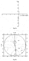
- Figures 1a to 1c illustrate the effect of an error on the positioning parameters on the astigmatism of the resulting ophthalmic lens.
- Figures 1a to 1c are two dimensional maps of a progressive addition lens of the type Varilux® PanamicTM with a front face of 2.12 dioptres and a rear face with a sphere of -7.75 a cylinder of 2.75 and addition of 2.75.
- the two dimensional maps represent the distribution of astigmatism as perceived by the wearer.
- FIG. 1a to 1c the front and back surfaces of the lens are the same the only differences lay in the position of the back surface.
- the back surface is translated of 2mm along the x-axis and the y-axis.
- the back surface is translated of 2mm along the x-axis and the y-axis and rotated of 5° around the a-axis.
- Figures 2 and 3 provide examples of the influence of the deformation step of the process according to the invention.
- a nominal progressive surface is compared to deformed progressive surface.
- the deformed progressive surface corresponds to the nominal progressive surface to which a spherical deformation of 0.1 dioptre was added.
- Figures 2a to 2d illustrate the features of a third surface corresponding to the difference between the nominal surface and the deformed surface obtained using a prior art process.
- Such prior art process consist in determining the position parameter that minimize the difference between the deformed surface and the nominal surface.
- the inventors have run the prior art process as if the deformed surface was a measured surface corresponding to a manufactured surface.
- the prior art process provides the position parameters of the deformed surface. By using such position parameters one can determine the features of corresponding ophthalmic lens.
- the features of the determined ophthalmic lens are represented on figure 2a to 2d .
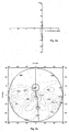
- Figure 2a represents the power profile of the sags difference between the measured progressive lens and its nominal surface, obtained using the prior art process.
- Figure 2b represents the sphere distribution of this difference obtained using the prior art process.
- Figure 2c represents the cylinder distribution of this difference obtained using the prior art process.
- Figure 2d represents the gap in microns between the measured progressive lens and its nominal surface, obtained using the prior art process.
- the power profile represented in figure 2a should be a straight line corresponding to 0.1 diopter and the sphere and cylinder distributions should be blank since the sphere should always be equal to 0.1 diopter and the cylinder should be equal to 0.
- a nominal progressive surface is compared to deformed progressive surface.
- the deformed progressive surface corresponds to the nominal progressive surface to which a progressive surface of 0.1 diopter of addition was added.
- Figures 3a to 3d illustrate the features of a third surface corresponding to the difference between the nominal surface and the deformed surface obtained using a prior art process.
- Such prior art process consist in determining the position parameter that minimize the difference between the deformed surface and the nominal surface.
- the inventors have run the prior art process as if the deformed surface was a measured surface corresponding to a manufactured surface.
- the prior art process provides the position parameters of the deformed surface. By using such position parameters one can determine the features of corresponding ophthalmic lens.
- the features of the determined ophthalmic lens are represented on figure 3a to 3d .
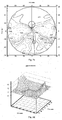
- Figure 3a represents the power profile of the sags difference between of the measured surface of the progressive lens and its nominal surface, obtained using the prior art process.
- Figure 3b represents the sphere distribution of this difference obtained using the prior art process.
- Figure 3c represents the cylinder distribution of this difference obtained using the prior art process.
- Figure 3d represents the gap in microns between the measured progressive lens and its nominal surface, obtained using the prior art process.
- the difference between the nominal surface and the deformation surface should be a progressive surface of 0.1D of addition.
- Figure 4 illustrated step (i) of a process according to the invention.
- a step (i) for determining position parameters defining the relative position of a manufactured derivable surface of a lens relative to a reference surface.
- step (i) comprises:
- the manufactured derivable surface is a surface of an optical lens.
- the manufactured surface may be a non-symmetric derivable surface.
- a nominal surface expressed in a nominal frame of reference and corresponding to the theoretical derivable surface to be manufactured with the nominal value of the position parameters defining the relative position of the nominal surface relative to the reference surface is provided.
- the positioning parameters may comprise at least six parameters, for example, three translation coefficients along the axis of the nominal frame and three rotation coefficients around the axis of the nominal frame.
- a measured surface of the manufactured derivable surface expressed in the nominal frame of reference is provided.
- the manufactured derivable surface is manufactured, it is measured using optical measurements and said measured surface is expressed in the same nominal frame of reference as the nominal surface provided in the nominal surface providing step S1.
- the process according to the invention comprise a deformation surface providing step S3 during which at least one deformation surface defined by at least one deformation parameter is provided.
- one of the deformation surface may be a sphero-torus surface defined by a sphere parameter, a cylinder parameter and an axis parameter.
- one of the deformation surface may correspond to a right circular cone defined by an axis parameter and an angle parameter.
- the deformation surface providing step of the process according to the invention may comprise providing a plurality of deformation surfaces.
- the process further comprises a composed surface step S4 during which a composed surface is determined by adding the measured surface and all the different deformation surfaces.
- the position parameters defining the position of the measured surface relative to the reference surface in the nominal frame of reference and the deformation parameters defining the different deformation of the different deformation surfaces are determined.
- the parameters are determined during the parameters determining step S5 by minimizing the difference between the nominal surface and the composed surface.
- the parameters determining step S5 further comprises a zone determining step in which a zone of interest is determined in the nominal surface and the position and deformation parameters are determined by minimizing as much as possible the difference between the nominal surface and the composed surface in the zone of interest.
- the parameters determining step S5 is implemented by using a damped least squares process.
- the invention also relates to a method for controlling a manufacturing process for example a lens manufacturing process.
- a lens manufacturing process using a manufacturing device comprises the steps of providing 10 a lens blank, blocking 12 the lens blank using a blocking device, machining 14 one surface of the lens blank using a machining device, for example a generator or 3D coarse grinding machining device and polishing 16 the machined surface of the lens using a polisher.
- the manufacturing steps 10 to 16 are repeated n times. After n repetitions of the manufacturing steps a controlling process according to the invention is processed.
- the manufacturing process according the invention can be used to manufacture any type of lens, for example ophthalmic lens such as for example progressive additional lens.
- the lens blank provided during the providing step 10 can be a semi-finished lens blank.
- the blocking step can be processed using any blocking devices known from the man skilled in the art; such a device is disclosed for example in patent documents US 4,229,911 or WO 2006/031687 .
- the manufacturing step 14 consists in generating a desired design on the unfinished surface of the lens.
- Generators are common devices known from the man skilled in the art; such a device is disclosed for example in patent documents EP 0 849 038 or US 2005/0188516 .
- the polishing step 16 consists in smoothing the manufactured surface. Polishing devices are well known in the art.
- lenses can be manufactured using the manufacturing process according to the invention.
- Such a manufacturing process can be controlled by a controlling process according to the invention as illustrated on fig. 6 , and comprising the steps of:
- the master lenses can be manufactured several times per day or be manufactured on a regular basis not every day.
- the master lens has a different geometrical and/or optical parameter and/or is made of a different material than the lenses to be manufactured during the manufacturing process.
- the choice of the master lens can be done so as to amplify the sensibility of certain parameter to the process parameters.
- the master lens is made of a material and has a design such as its optical parameters are more sensitive to a modification of the process parameter that the usual manufactured lenses.
- the inventors have observed a correlation between the deformation parameters that can be determined using the method according to the invention and the manufacturing parameters.
- the inventors have observed a correlation between the sphere, cylinder and axis parameters of the sphero-torus deformation surface and the way the optical lens is blocked during the manufacturing device.
- the inventors have also observed that when the deformation surface corresponds to a right circular cone defined by an axis parameter and an angle parameter, said parameters can be correlated to the positioning of the grinding tool during the manufacturing process.
- the process according to the invention allows not only to detect a defect in the manufacturing process but also thanks to the determination of the deformation parameters to identifies where in the manufacturing process a defect is starting to appear.
Landscapes
- Engineering & Computer Science (AREA)
- Physics & Mathematics (AREA)
- Mechanical Engineering (AREA)
- Health & Medical Sciences (AREA)
- General Physics & Mathematics (AREA)
- Ophthalmology & Optometry (AREA)
- General Health & Medical Sciences (AREA)
- Manufacturing & Machinery (AREA)
- Business, Economics & Management (AREA)
- Optics & Photonics (AREA)
- Primary Health Care (AREA)
- Economics (AREA)
- Human Resources & Organizations (AREA)
- Marketing (AREA)
- Microelectronics & Electronic Packaging (AREA)
- Strategic Management (AREA)
- Tourism & Hospitality (AREA)
- General Business, Economics & Management (AREA)
- Theoretical Computer Science (AREA)
- Analytical Chemistry (AREA)
- Geometry (AREA)
- Chemical & Material Sciences (AREA)
- Automation & Control Theory (AREA)
- Human Computer Interaction (AREA)
- Eyeglasses (AREA)
- Exposure Of Semiconductors, Excluding Electron Or Ion Beam Exposure (AREA)
- Jigs For Machine Tools (AREA)
- Mechanical Treatment Of Semiconductor (AREA)
Description
- The invention relates to a process implemented by computer means for determining position parameters defining the relative position of a manufactured derivable surfaces relative to a reference surface, to a manufacturing process and to a process for controlling such manufacturing process.
- Optical lenses, and in particular ophthalmic lenses, require very high quality manufacturing process in order to obtain high quality optical lenses.
- Historically, optical lenses have been manufactured by different processes such as cast molding.
- However, the molding method presents limitation in terms of cost.
- Therefore, new manufacturing techniques such as digital surfacing are used.
- Whereas to control the quality of the lenses produced using cast molding process, one can check the quality of the mold being used, such quality control is not possible when using the digital surfacing process. One could check each individual lens however such quality control would be very time consuming and present a limitation in terms of costs.
- Therefore, quality control process has been developed that allow controlling the quality of the lenses produced using a digital surfacing process by controlling the quality of the manufacturing process it self. An example of such a process that allows checking efficiently the quality of the digital surfacing process is disclosed in
EP 08 853 275 - The inventors have observed that the results provided by such process may not be entirely satisfactory. In particular, the inventors have observed that after such analyzing process the results may comprise certain artifacts.
- Therefore, there is a need to improve such quality analyzing process in order to strengthen the control of the manufacturing process and the quality of manufactured lenses. Thus, a goal of the present invention is to provide such a analyzing process.
-
EP0359084 describes a contact lens manufacturing method of machining a contact lens raw material to a desired shape, comprising a first machining step of forming a base curve and a bevel having given shapes on the basis of given design data, a radius-of-curvature measuring step of measuring the radius of curvature of the base curve and calculating the radius-of-curvature data of a front curve for attainment of a desired refractive power, and a second machining step of forming the front curve having a given shape, and a lentic curve if necessary, on the basis of the radius-of-curvature data calculated. - The invention relates to a process implemented by computer means for controlling an ophthalmic lens manufacturing process, characterized in that it comprises: (i) a step of determining at least six position parameters defining the relative position of a manufactured derivable surface of said lens relative to a reference surface, wherein said step of determining at least six position parameters comprises:
- a nominal surface providing step during which a nominal surface expressed in a nominal frame of reference and corresponding to the theoretical derivable surface to be manufactured with the nominal value of the position parameters defining the relative position of the nominal surface relative to the reference surface is provided,
- a measured surface providing step during which a measured surface of the manufactured derivable surface expressed in the nominal frame of reference is provided,
- a deformation surface providing step during which at least one deformation surface defined by at least one adjustable deformation parameter is provided,
- a composed surface determining step during which a composed surface is determined by adding the measured surface and the deformation surface,
- a parameters determining step during which the position parameters and at least one deformation parameter are determined by minimizing the difference between the nominal surface and the composed surface;
- (i) a error surface determining step during which the error surface corresponding to the difference between the measured surface positioned relative to the reference surface by using the six position parameters and the nominal surface is determined,
- (ii) a controlling step during which the error surface is controlled.
- Advantageously, the method according to the invention allows determining the position parameters defining the relative position of the manufactured derivable surface of said lens relative to the reference surface.
- Indeed, the inventors have observed that the positioning parameters are first-order factors in the quality measurements of any digital surfacing process.
- The position parameters that are determined using the process according to the invention comprise less artifact than when obtained using the method of the prior art. Furthermore, the process according to the invention allows determining at least one deformation parameter.
- According to further embodiments which can be considered alone or in combination:
- the parameter determining step further comprises a zone determining step in which a zone of interest is determined in the nominal surface and the position and deformation parameters are determined by minimizing the difference between the nominal surface and the composed surface in the zone of interest; and/or
the parameter determining step is implemented by using a damped least squares process; and/or - the manufactured derivable surface is a surface of an ophthalmic lens; and/or
- the measured surface is determined by optical measurements; and/or
- the manufactured derivable surface is a non-symmetric derivable surface; and/or
- the position parameters comprise at least six parameters, for example three translation coefficients and three rotation coefficients; and/or
- the deformation surface corresponds to a sphero-torus surface defined by a sphere parameter, a cylinder parameter and an axis parameter; and/or
- the deformation surface corresponds to a right circular cone defined by an axis parameter and an angle parameter.
- According to another aspect, the invention relates to a process for controlling a manufacturing process, comprising the steps of the process according to the preceding claims and further comprising:
- an error surface determining step during which the error surface corresponding to the difference between the measured surface positioned relative to the reference surface by using the six position parameters and the nominal surface is determined,
- a controlling step during which the error surface is controlled.
- The invention also relates to a process for controlling a lens manufacturing process comprising the steps of:
- a)manufacturing a master lens according to a manufacturing process using a manufacturing device,
- b) determining by the step (i) according to the invention at least one deformation parameter of the master lens of step a),
- c) recording the value of the at least one deformation parameter,
- d) repeating regularly step a) to c) and checking the evolution of the at least one deformation parameter over time,
- The invention further relates to a manufacturing process for manufacturing a lens using a manufacturing device comprising the steps of:
- providing a lens blank,
- blocking the lens blank,
- surfacing at least one surface of the lens blank,
- According to an embodiment, the process includes an ophthalmic progressive lens surfacing process, for example a digital surfacing process.
- The invention also relates to a computer program product for a data processing device, the computer program product comprising a set of instructions which, when loaded into the data processing device, causes the data processing device to perform at least one of the steps, for example all of the steps, of the method according to the invention.
- In addition, the present invention provides a computer-readable medium carrying one or more set of instructions of a computer program product of the invention.
- Unless specifically stated otherwise, as apparent from the following discussions, it is appreciated that throughout the specification discussions utilizing terms such as "computing", "calculating", "generating", or the like, refer to the action and/or processes of a computer or computing system, or similar electronic computing device, that manipulate and/or transform data represented as physical, such as electronic, quantities within the computing system's registers and/or memories into other data similarly represented as physical quantities within the computing system's memories, registers or other such information storage, transmission or display devices. Embodiments of the present invention may include apparatuses for performing the operations herein. This apparatus may be specially constructed for the desired purposes, or it may comprise a general purpose computer or Digital Signal Processor ("DSP") selectively activated or reconfigured by a computer program stored in the computer. Such a computer program may be stored in a computer readable storage medium, such as, but is not limited to, any type of disk including floppy disks, optical disks, CD-ROMs, magnetic-optical disks, read-only memories (ROMs), random access memories (RAMs) electrically programmable read-only memories (EPROMs), electrically erasable and programmable read only memories (EEPROMs), magnetic or optical cards, or any other type, of media suitable for storing electronic instructions, and capable of being coupled to a computer system bus. The processes and displays presented herein are not inherently related to any particular computer or other apparatus. Various general purpose systems may be used with programs in accordance with the teachings herein, or it may prove convenient to construct a more specialized apparatus to perform the desired method. The desired structure for a variety of these systems will appear from the description below. In addition, embodiments of the present invention are not described with reference to any particular programming language. It will be appreciated that a variety of programming languages may be used to implement the teachings of the inventions as described herein.
- In the sense of the invention "the manufacturing parameters" are the setting parameter of the different manufacturing devices involved in the manufacturing process. In the sense of the invention "the process parameter" includes any measurable parameters on the manufacturing devices used for the manufacturing of the lens.
- Non limiting embodiments of the invention will now be described with reference to the accompanying drawing wherein:
-
Figures 1a to 1c illustrate the influence of the positioning parameters of a surface of an ophthalmic lens on the distribution of astigmatism of said lens; -
Figures 2a to 2d illustrate the results of a prior art process for determining the difference between a nominal surface and a measured surface; -
Figures 3a to 3d illustrate the results of a prior art process for determining the difference between a nominal surface and a measured surface; -
Figure 4 is a flowchart of the steps comprised in a process for determining the positioning parameters according to an embodiment of the invention; -
Figure 5 is a flowchart of the steps comprised in a manufacturing process according to an embodiment of the invention; and -
Figure 6 is a flowchart of the steps comprised in a controlling process according to an embodiment of the invention. -
Figures 1a to 1c illustrate the effect of an error on the positioning parameters on the astigmatism of the resulting ophthalmic lens. -
Figures 1a to 1c are two dimensional maps of a progressive addition lens of the type Varilux® Panamic™ with a front face of 2.12 dioptres and a rear face with a sphere of -7.75 a cylinder of 2.75 and addition of 2.75. - The two dimensional maps represent the distribution of astigmatism as perceived by the wearer.
-
Figure 1a to 1c the front and back surfaces of the lens are the same the only differences lay in the position of the back surface. - In
figure, 1a the back surface is correctly positioned. - In
figure 1b , the back surface is translated of 2mm along the x-axis and the y-axis. - In
figure 1c , the back surface is translated of 2mm along the x-axis and the y-axis and rotated of 5° around the a-axis. - As it appears from
figures 1a to 1c , the difference in position of the back surface implies a great effect on the distribution of astigmatism as perceived by the wearer. - Thus, it is of great importance to be able to determine correctly the positioning parameters of the back surface. Besides, it is important not to mix up these changes of distribution of astigmatism (or power error) with changes caused by surface deformation. It is of great importance to be able to separate and distinguish the real causes of changes of distribution of wearer astigmatism (or more generally wearer power error), for both positioning errors and surface deformation errors.
-
Figures 2 and3 provide examples of the influence of the deformation step of the process according to the invention. - In the example of
figures 2a to 2d a nominal progressive surface is compared to deformed progressive surface. The deformed progressive surface corresponds to the nominal progressive surface to which a spherical deformation of 0.1 dioptre was added. - When comparing the nominal and deformed surfaces, one should obtain a third surface correspond to a part of a sphere of 0.1 diopter.
-
Figures 2a to 2d illustrate the features of a third surface corresponding to the difference between the nominal surface and the deformed surface obtained using a prior art process. Such prior art process consist in determining the position parameter that minimize the difference between the deformed surface and the nominal surface. - The inventors have run the prior art process as if the deformed surface was a measured surface corresponding to a manufactured surface. The prior art process provides the position parameters of the deformed surface. By using such position parameters one can determine the features of corresponding ophthalmic lens. The features of the determined ophthalmic lens are represented on
figure 2a to 2d . -
Figure 2a represents the power profile of the sags difference between the measured progressive lens and its nominal surface, obtained using the prior art process. -
Figure 2b represents the sphere distribution of this difference obtained using the prior art process. -
Figure 2c represents the cylinder distribution of this difference obtained using the prior art process. -
Figure 2d represents the gap in microns between the measured progressive lens and its nominal surface, obtained using the prior art process. - Since the difference between the nominal surface and the progressive surface is a uniform deformation of 0.1 diopter, the power profile represented in
figure 2a should be a straight line corresponding to 0.1 diopter and the sphere and cylinder distributions should be blank since the sphere should always be equal to 0.1 diopter and the cylinder should be equal to 0. - As illustrated by
figures 2a to 2d , the prior art process results in generating differences between the nominal surface and the deformed surface that actually do not exists. - In the example of
figures 3a to 3d a nominal progressive surface is compared to deformed progressive surface. The deformed progressive surface corresponds to the nominal progressive surface to which a progressive surface of 0.1 diopter of addition was added. - When comparing the nominal and deformed surfaces, one should obtain a third surface correspond to a progressive surface of 0.1 diopter of addition
-
Figures 3a to 3d illustrate the features of a third surface corresponding to the difference between the nominal surface and the deformed surface obtained using a prior art process. Such prior art process consist in determining the position parameter that minimize the difference between the deformed surface and the nominal surface. - The inventors have run the prior art process as if the deformed surface was a measured surface corresponding to a manufactured surface. The prior art process provides the position parameters of the deformed surface. By using such position parameters one can determine the features of corresponding ophthalmic lens. The features of the determined ophthalmic lens are represented on
figure 3a to 3d . -
Figure 3a represents the power profile of the sags difference between of the measured surface of the progressive lens and its nominal surface, obtained using the prior art process. -
Figure 3b represents the sphere distribution of this difference obtained using the prior art process. -
Figure 3c represents the cylinder distribution of this difference obtained using the prior art process. -
Figure 3d represents the gap in microns between the measured progressive lens and its nominal surface, obtained using the prior art process. - The difference between the nominal surface and the deformation surface should be a progressive surface of 0.1D of addition.
- As illustrated by
figures 3a to 3d , the prior art process results in generating differences between the nominal surface and the deformed surface that actually do not exists. - From the above mentioned example that there is a need for a process to correctly position the measured surface with respect to the nominal surface and to determined deformation coefficient.
-
Figure 4 illustrated step (i) of a process according to the invention. - As illustrated on
figure 4 , a step (i) according to the invention for determining position parameters defining the relative position of a manufactured derivable surface of a lens relative to a reference surface. Such step (i) comprises: - a nominal surface providing step S1,
- a measured surface providing step S2,
- a deformation surface providing step S3,
- a composed surface determining step S4, and
- a parameter determining step S5.
- According to the embodiments describe hereafter, the manufactured derivable surface is a surface of an optical lens. In particular, the manufactured surface may be a non-symmetric derivable surface.
- During the nominal surface providing step S1, a nominal surface expressed in a nominal frame of reference and corresponding to the theoretical derivable surface to be manufactured with the nominal value of the position parameters defining the relative position of the nominal surface relative to the reference surface is provided.
- The positioning parameters may comprise at least six parameters, for example, three translation coefficients along the axis of the nominal frame and three rotation coefficients around the axis of the nominal frame.
- In the measured surface providing step S2, a measured surface of the manufactured derivable surface expressed in the nominal frame of reference is provided.
- For example, after the manufactured derivable surface is manufactured, it is measured using optical measurements and said measured surface is expressed in the same nominal frame of reference as the nominal surface provided in the nominal surface providing step S1.
- The process according to the invention comprise a deformation surface providing step S3 during which at least one deformation surface defined by at least one deformation parameter is provided.
- According to an embodiment of the invention, one of the deformation surface may be a sphero-torus surface defined by a sphere parameter, a cylinder parameter and an axis parameter.
- According to an embodiment of the invention, one of the deformation surface may correspond to a right circular cone defined by an axis parameter and an angle parameter.
- The deformation surface providing step of the process according to the invention may comprise providing a plurality of deformation surfaces.
- Indeed, the inventors have observed that it is possible to link the coefficient defining the deformation surface and some manufacturing parameters of the manufacturing process. Therefore, it may be interesting to provide as many deformation surfaces as possible in order to be able to control as many manufacturing parameters as possible.
- According to the process of the invention, after having provided the deformation surfaces, the process further comprises a composed surface step S4 during which a composed surface is determined by adding the measured surface and all the different deformation surfaces.
- During the parameters determining step S5, the position parameters defining the position of the measured surface relative to the reference surface in the nominal frame of reference and the deformation parameters defining the different deformation of the different deformation surfaces are determined.
- According to an embodiment of the invention, the parameters are determined during the parameters determining step S5 by minimizing the difference between the nominal surface and the composed surface.
- According to an embodiment of the invention, the parameters determining step S5 further comprises a zone determining step in which a zone of interest is determined in the nominal surface and the position and deformation parameters are determined by minimizing as much as possible the difference between the nominal surface and the composed surface in the zone of interest.
- According to an embodiment of the invention, the parameters determining step S5 is implemented by using a damped least squares process.
- The invention also relates to a method for controlling a manufacturing process for example a lens manufacturing process.
- As illustrated in
figure 5 , a lens manufacturing process using a manufacturing device comprises the steps of providing 10 a lens blank, blocking 12 the lens blank using a blocking device, machining 14 one surface of the lens blank using a machining device, for example a generator or 3D coarse grinding machining device and polishing 16 the machined surface of the lens using a polisher. - The manufacturing steps 10 to 16 are repeated n times. After n repetitions of the manufacturing steps a controlling process according to the invention is processed.
- The manufacturing process according the invention can be used to manufacture any type of lens, for example ophthalmic lens such as for example progressive additional lens.
- The lens blank provided during the providing
step 10 can be a semi-finished lens blank. - The blocking step can be processed using any blocking devices known from the man skilled in the art; such a device is disclosed for example in patent documents
US 4,229,911 orWO 2006/031687 . - The manufacturing step 14 consists in generating a desired design on the unfinished surface of the lens. Generators are common devices known from the man skilled in the art; such a device is disclosed for example in
patent documents EP 0 849 038 orUS 2005/0188516 . - The polishing step 16 consists in smoothing the manufactured surface. Polishing devices are well known in the art.
- Once the manufacturing parameters have been properly calibrated using for example a qualification process as disclosed in
EP 08 853 275 - Such a manufacturing process can be controlled by a controlling process according to the invention as illustrated on
fig. 6 , and comprising the steps of: - a) manufacturing a
master lens 20 according to a manufacturing process using a manufacturing device, - b) determining by the process according to the invention at least one deformation parameter of the
mater lens 22 of step a), - c) recording the value of said
deformation parameter 24, - d) repeating regularly step a) to c) and checking 28 the evolution of said deformation parameter over time.
- According to an embodiment of the invention, the master lenses can be manufactured several times per day or be manufactured on a regular basis not every day.
- According to an embodiment of the invention the master lens has a different geometrical and/or optical parameter and/or is made of a different material than the lenses to be manufactured during the manufacturing process.
- The choice of the master lens can be done so as to amplify the sensibility of certain parameter to the process parameters. For example, the master lens is made of a material and has a design such as its optical parameters are more sensitive to a modification of the process parameter that the usual manufactured lenses.
- Examples of master lens design are given in
EP 08 853 275 - The inventors have observed a correlation between the deformation parameters that can be determined using the method according to the invention and the manufacturing parameters.
- For example, the inventors have observed a correlation between the sphere, cylinder and axis parameters of the sphero-torus deformation surface and the way the optical lens is blocked during the manufacturing device.
- Therefore, by determining the sphere, cylinder and axis parameters using the process according to the invention on master lens manufactured regularly, it is possible to detect a defect in the blocking step.
- The inventors have also observed that when the deformation surface corresponds to a right circular cone defined by an axis parameter and an angle parameter, said parameters can be correlated to the positioning of the grinding tool during the manufacturing process.
- Therefore, the process according to the invention allows not only to detect a defect in the manufacturing process but also thanks to the determination of the deformation parameters to identifies where in the manufacturing process a defect is starting to appear.
- The previous examples of deformation parameters are included to illustrate embodiment of the invention. It should be appreciated by those of skill in the art that the techniques disclosed in theses examples represent techniques observed by the inventors to function well in the practice of the invention, and thus can be considered to constitute preferred modes for its practice. However, those of skill in the art should, in light of the present disclosure, appreciate that many changes can be made in the specific embodiments which are disclosed and still obtain a like or similar result without departing from the scope of the invention defined by the following claims.
Claims (13)
- Process implemented by computer means for controlling an ophthalmic lens manufacturing process, characterized in that it comprises:(i) a step of determining at least six position parameters defining the relative position of a manufactured derivable surface of said lens relative to a reference surface, wherein said step of determining at least six position parameters comprises:- a nominal surface providing step (S1) during which a nominal surface expressed in a nominal frame of reference and corresponding to the theoretical derivable surface to be manufactured with the nominal value of the position parameters defining the relative position of the nominal surface relative to the reference surface is provided,- a measured surface providing step (S2) during which a measured surface of the manufactured derivable surface expressed in the nominal frame of reference is provided,- a deformation surface providing step (S3) during which at least one deformation surface defined by at least one adjustable deformation parameter is provided,- a composed surface determining step (S4) during which a composed surface is determined by adding the measured surface and the deformation surface,- a parameters determining step (S5) during which the position parameters and at least one deformation parameter are determined by minimizing the difference between the nominal surface and the composed surface,and in that at further comprises:(ii) an error surface determining step during which the error surface corresponding to the difference between the measured surface positioned relative to the reference surface by using the six position parameters and the nominal surface is determined,(iii) a controlling step during which the error surface is controlled.
- Process according to claim 1, wherein the parameter determining step further comprises a zone determining step in which a zone of interest is determined in the nominal surface and the position and deformation parameters are determined by minimizing the difference between the nominal surface and the composed surface in the zone of interest.
- Process according to any of claims 1 or 2, wherein the parameter determining step is implemented by using a damped least squares process.
- Process according to any of the preceding claims wherein the measured surface is determined by optical measurements.
- Process according to any of the preceding claims, wherein the manufactured derivable surface is a non-symmetric derivable surface.
- Process according to any of the preceding claims, wherein the at least six position parameters comprise three translation coefficients and three rotation coefficients.
- Process according to any of the preceding claims, wherein the deformation surface corresponds to a sphero-torus surface defined by a sphere parameter, a cylinder parameter and an axis parameter.
- Process according to any of the preceding claims, wherein the deformation surface corresponds to a right circular cone defined by an axis parameter and an angle parameter.
- Process for controlling a lens manufacturing process characterized in that it comprises the steps of:a)manufacturing a master lens according to a manufacturing process using a manufacturing device,b) determining by the step (i) according to any of claims 1 to 8 at least one deformation parameter of the master lens of step a),c) recording the value of the at least one deformation parameter,d) repeating regularly step a) to c) and checking the evolution of the at least one deformation parameter over time,wherein the evolution of at least one parameter of the manufacturing device used during the lens manufacturing process is checked over time and the evolution over time of at least one deformation parameter of the master lens is related with the evolution over time of the at least one parameter of the manufacturing device.
- Manufacturing process for manufacturing a lens using a manufacturing device, characterized in that it comprises the steps of:- providing a lens blank,- blocking the lens blank,- surfacing at least one surface of the lens blank,characterized in that the manufacturing process is checked by a process according to claim 9.
- The process according to any of the preceding claims, characterized in that the process includes an ophthalmic progressive lens surfacing process, for example a digital surfacing process.
- A computer program product for a data-processing device, characterized in that the computer program product comprises a set of instructions which, when loaded into the data-processing device, causes the device to perform the steps of the processes as claimed in claim 1 to 11.
- A computer-readable medium carrying one or more sequences of instructions of the computer program product of claim 12.
Priority Applications (11)
| Application Number | Priority Date | Filing Date | Title |
|---|---|---|---|
| EP11305581.8A EP2522458B1 (en) | 2011-05-13 | 2011-05-13 | Process for determining position parameters of a manufactured surface relative to a reference surface |
| JP2014509763A JP6072006B2 (en) | 2011-05-13 | 2012-05-11 | Method for determining a position parameter of a surface to be manufactured relative to a reference surface |
| CN201280022607.9A CN103517784B (en) | 2011-05-13 | 2012-05-11 | Method for determining positional parameters of a fabrication surface relative to a reference surface |
| MX2013013222A MX348443B (en) | 2011-05-13 | 2012-05-11 | Process for determining position parameters of a manufactured surface relative to a reference surface. |
| US14/116,659 US9291522B2 (en) | 2011-05-13 | 2012-05-11 | Process for determining position parameters of a manufactured surface relative to a reference surface |
| KR1020137027866A KR101804367B1 (en) | 2011-05-13 | 2012-05-11 | Process for determining position parameters of a manufactured surface relative to a reference surface |
| BR112013029130-3A BR112013029130B1 (en) | 2011-05-13 | 2012-05-11 | PROCESS TO DETERMINE POSITION PARAMETERS OF A MANUFACTURED SURFACE IN RELATION TO THE REFERENCE SURFACE, PROCESS TO CONTROL A LENS MANUFACTURING PROCESS AND MANUFACTURING PROCESS TO MANUFACTURE A LENS |
| RU2013155450/02A RU2013155450A (en) | 2011-05-13 | 2012-05-11 | METHOD FOR DETERMINING POSITION PARAMETERS OF A MANUFACTURED SURFACE WITH RESPECT TO THE CONTROL SURFACE |
| CA2833088A CA2833088C (en) | 2011-05-13 | 2012-05-11 | Process for determining position parameters of a manufactured surface relative to a reference surface |
| PCT/EP2012/058806 WO2012156322A1 (en) | 2011-05-13 | 2012-05-11 | Process for determining position parameters of a manufactured surface relative to a reference surface |
| AU2012257790A AU2012257790B2 (en) | 2011-05-13 | 2012-05-11 | Process for determining position parameters of a manufactured surface relative to a reference surface |
Applications Claiming Priority (1)
| Application Number | Priority Date | Filing Date | Title |
|---|---|---|---|
| EP11305581.8A EP2522458B1 (en) | 2011-05-13 | 2011-05-13 | Process for determining position parameters of a manufactured surface relative to a reference surface |
Publications (2)
| Publication Number | Publication Date |
|---|---|
| EP2522458A1 EP2522458A1 (en) | 2012-11-14 |
| EP2522458B1 true EP2522458B1 (en) | 2016-07-06 |
Family
ID=46085034
Family Applications (1)
| Application Number | Title | Priority Date | Filing Date |
|---|---|---|---|
| EP11305581.8A Active EP2522458B1 (en) | 2011-05-13 | 2011-05-13 | Process for determining position parameters of a manufactured surface relative to a reference surface |
Country Status (11)
| Country | Link |
|---|---|
| US (1) | US9291522B2 (en) |
| EP (1) | EP2522458B1 (en) |
| JP (1) | JP6072006B2 (en) |
| KR (1) | KR101804367B1 (en) |
| CN (1) | CN103517784B (en) |
| AU (1) | AU2012257790B2 (en) |
| BR (1) | BR112013029130B1 (en) |
| CA (1) | CA2833088C (en) |
| MX (1) | MX348443B (en) |
| RU (1) | RU2013155450A (en) |
| WO (1) | WO2012156322A1 (en) |
Families Citing this family (10)
| Publication number | Priority date | Publication date | Assignee | Title |
|---|---|---|---|---|
| EP2920568B1 (en) * | 2012-11-14 | 2018-05-16 | Essilor International | Method of determining optical parameters of an opthalmic lens |
| BR112015011025B1 (en) | 2012-11-14 | 2021-02-23 | Essilor International | method, implanted by means of a computer, to determine the viability of an ophthalmic lens by an ophthalmic lens manufacturing process |
| WO2016193771A1 (en) | 2015-05-29 | 2016-12-08 | Essilor International (Compagnie Generale D'optique) | System and method for compensating deviations in an optical lens manufacturing process |
| EP3330064B1 (en) | 2016-11-30 | 2025-07-16 | Essilor International | Method for manufacturing an ophtalmic article |
| GB2557952B (en) * | 2016-12-16 | 2022-06-15 | Zeeko Innovations Ltd | Methods and apparatus for shaping workpieces |
| DE102018204948A1 (en) * | 2018-03-29 | 2019-10-02 | Rodenstock Gmbh | Method for fixing a raw-edged finished spectacle lens and device therefor |
| KR102070245B1 (en) | 2018-08-13 | 2020-01-28 | 정지수 | Metal accessory having contactless-type wireless communication function and method of fabricating the metal accessory |
| EP4083686A4 (en) * | 2019-12-24 | 2024-01-03 | Hoya Lens Thailand Ltd. | Semifinished lens and method for manufacturing spectacle lens |
| CN114425732B (en) * | 2022-04-06 | 2022-06-03 | 中国工程物理研究院激光聚变研究中心 | Automatic optimization method, system and medium for sub-caliber processing technology |
| CN118882550B (en) * | 2024-07-09 | 2025-10-31 | 奇瑞汽车股份有限公司 | Automobile roof ergonomic verification device |
Family Cites Families (20)
| Publication number | Priority date | Publication date | Assignee | Title |
|---|---|---|---|---|
| US4229911A (en) | 1978-04-03 | 1980-10-28 | Bicskei Bela J | Precision blocking of semi-finished lens blanks |
| JP2797333B2 (en) * | 1988-09-16 | 1998-09-17 | セイコーエプソン株式会社 | Method and apparatus for manufacturing contact lens |
| JP3072202B2 (en) * | 1992-12-11 | 2000-07-31 | ホーヤ株式会社 | Eyeglass lens processing apparatus and processing method |
| GB9604927D0 (en) | 1996-03-08 | 1996-05-08 | Allied Colloids Ltd | Activation of swelling clays and processes of using the activated clays |
| DE19653233A1 (en) | 1996-12-20 | 1998-07-02 | Schneider Gmbh & Co Kg | High-speed lathe for the production of optically effective surfaces |
| DE19727226A1 (en) * | 1997-04-10 | 1998-10-22 | Fraunhofer Ges Forschung | Contactless measuring device for spectacles frame |
| ATE316257T1 (en) * | 2000-04-28 | 2006-02-15 | Rodenstock Gmbh | METHOD FOR PRODUCING GLASSES |
| JP3851495B2 (en) * | 2000-07-07 | 2006-11-29 | ペンタックス株式会社 | Eyeglass lens design method, manufacturing method, and eyeglass lens |
| DE10103113A1 (en) * | 2001-01-24 | 2002-08-01 | Rodenstock Optik G | Process for the manufacture of spectacle lenses |
| JP2002350785A (en) * | 2001-05-28 | 2002-12-04 | Menicon Co Ltd | How to design ophthalmic lenses |
| FR2825308B1 (en) * | 2001-06-05 | 2003-10-10 | Essilor Int | AUTOMATIC OR SEMI-AUTOMATIC DEVICE FOR CLIPPING AN OPHTHALMIC LENS |
| DE10348459C5 (en) | 2003-10-14 | 2011-06-09 | Schneider Gmbh & Co. Kg | Apparatus and method for machining lenses |
| WO2006031687A2 (en) | 2004-09-15 | 2006-03-23 | Gerber Scientific, Inc. | Automatic blocking and lens blank measuring apparatus and method |
| JP4232166B2 (en) * | 2006-01-31 | 2009-03-04 | 株式会社アイメトリクス・ジャパン | Glasses wearing simulation method and apparatus |
| FR2911696B1 (en) * | 2007-01-24 | 2009-10-30 | Essilor Int | PROGRESSIVE OPHTHALMIC GLASS WITH PERSONALIZED INSET. |
| JP2008258510A (en) * | 2007-04-07 | 2008-10-23 | Tokyo Seimitsu Co Ltd | Polish requirement management device for cmp device and method of managing polish requirement |
| CN101821663B (en) * | 2007-10-10 | 2012-02-08 | Hoya株式会社 | Progressive multifocal lens manufacturing method and progressive multifocal lens |
| CN101918178B (en) * | 2007-11-30 | 2013-07-10 | 依视路国际集团(光学总公司) | Control process of lens manufacturing process |
| EP2028527B1 (en) * | 2007-12-28 | 2013-01-23 | Essilor International (Compagnie Générale D'Optique) | Method for selecting base-curves for an ophtalmic lens and related spectacle lens manufacturing method |
| DE102008060589B4 (en) * | 2008-12-05 | 2015-06-03 | Schneider Gmbh & Co. Kg | Method for processing and calculating an optical lens designed as a semi-finished product |
-
2011
- 2011-05-13 EP EP11305581.8A patent/EP2522458B1/en active Active
-
2012
- 2012-05-11 US US14/116,659 patent/US9291522B2/en active Active
- 2012-05-11 MX MX2013013222A patent/MX348443B/en active IP Right Grant
- 2012-05-11 JP JP2014509763A patent/JP6072006B2/en active Active
- 2012-05-11 KR KR1020137027866A patent/KR101804367B1/en active Active
- 2012-05-11 WO PCT/EP2012/058806 patent/WO2012156322A1/en not_active Ceased
- 2012-05-11 AU AU2012257790A patent/AU2012257790B2/en active Active
- 2012-05-11 CN CN201280022607.9A patent/CN103517784B/en active Active
- 2012-05-11 CA CA2833088A patent/CA2833088C/en active Active
- 2012-05-11 BR BR112013029130-3A patent/BR112013029130B1/en active IP Right Grant
- 2012-05-11 RU RU2013155450/02A patent/RU2013155450A/en not_active Application Discontinuation
Also Published As
| Publication number | Publication date |
|---|---|
| MX2013013222A (en) | 2013-12-02 |
| EP2522458A1 (en) | 2012-11-14 |
| CA2833088C (en) | 2019-04-02 |
| BR112013029130A2 (en) | 2017-02-07 |
| US20140085627A1 (en) | 2014-03-27 |
| US9291522B2 (en) | 2016-03-22 |
| JP6072006B2 (en) | 2017-02-01 |
| WO2012156322A1 (en) | 2012-11-22 |
| BR112013029130A8 (en) | 2018-08-14 |
| MX348443B (en) | 2017-06-12 |
| KR20140045348A (en) | 2014-04-16 |
| RU2013155450A (en) | 2015-06-20 |
| CN103517784B (en) | 2017-04-12 |
| AU2012257790B2 (en) | 2016-04-21 |
| CA2833088A1 (en) | 2012-11-22 |
| CN103517784A (en) | 2014-01-15 |
| KR101804367B1 (en) | 2017-12-04 |
| BR112013029130B1 (en) | 2021-10-19 |
| AU2012257790A1 (en) | 2013-10-31 |
| JP2014517934A (en) | 2014-07-24 |
Similar Documents
| Publication | Publication Date | Title |
|---|---|---|
| CA2833088C (en) | Process for determining position parameters of a manufactured surface relative to a reference surface | |
| US8721076B2 (en) | Process for controlling a lens manufacturing process | |
| EP2789424B1 (en) | Lens shape finishing system of eyeglass lens, manufacturing method of eyeglass lenses, and lens shape finishing device | |
| CN104781644B (en) | The method for determining the optical parametric of ophthalmic len | |
| EP2667241A1 (en) | A method of manufacturing a spectacle lens providing an astigmatic correction and spectacles including such spectacle lens | |
| JP6300729B2 (en) | Method of deforming a progressive ophthalmic surface | |
| CN111133369B (en) | Method for evaluating ophthalmic lenses, associated evaluation systems, and industrial components for manufacturing ophthalmic lenses | |
| JP5026987B2 (en) | Lens surface cutting device for spectacle lens, lens surface cutting method and spectacle lens | |
| EP3020542A1 (en) | Method for controlling a lens manufacturing method | |
| EP2920640B1 (en) | Method for determining the feasibility of an ophthalmic lens | |
| JP6034582B2 (en) | Eyeglass lens manufacturing method, circumference calculation device, and circumference calculation program | |
| JP4711853B2 (en) | Improved tolerance determination method for progressive power eyeglass lens inspection |
Legal Events
| Date | Code | Title | Description |
|---|---|---|---|
| PUAI | Public reference made under article 153(3) epc to a published international application that has entered the european phase |
Free format text: ORIGINAL CODE: 0009012 |
|
| AK | Designated contracting states |
Kind code of ref document: A1 Designated state(s): AL AT BE BG CH CY CZ DE DK EE ES FI FR GB GR HR HU IE IS IT LI LT LU LV MC MK MT NL NO PL PT RO RS SE SI SK SM TR |
|
| AX | Request for extension of the european patent |
Extension state: BA ME |
|
| 17P | Request for examination filed |
Effective date: 20130514 |
|
| 17Q | First examination report despatched |
Effective date: 20140103 |
|
| REG | Reference to a national code |
Ref country code: DE Ref legal event code: R079 Ref document number: 602011027908 Country of ref document: DE Free format text: PREVIOUS MAIN CLASS: B24B0013000000 Ipc: B24B0049040000 |
|
| RIC1 | Information provided on ipc code assigned before grant |
Ipc: B24B 49/04 20060101AFI20150831BHEP Ipc: B24B 51/00 20060101ALI20150831BHEP Ipc: G01M 11/02 20060101ALI20150831BHEP Ipc: B29D 11/00 20060101ALI20150831BHEP Ipc: B24B 13/00 20060101ALI20150831BHEP Ipc: G01B 21/00 20060101ALI20150831BHEP Ipc: G02C 7/06 20060101ALI20150831BHEP Ipc: G06Q 50/04 20120101ALI20150831BHEP |
|
| GRAP | Despatch of communication of intention to grant a patent |
Free format text: ORIGINAL CODE: EPIDOSNIGR1 |
|
| INTG | Intention to grant announced |
Effective date: 20151019 |
|
| GRAS | Grant fee paid |
Free format text: ORIGINAL CODE: EPIDOSNIGR3 |
|
| RIN1 | Information on inventor provided before grant (corrected) |
Inventor name: ALLIONE, PASCAL Inventor name: STEIGELMANN, DANIEL Inventor name: CHAUVEAU, JEAN-PIERRE |
|
| GRAP | Despatch of communication of intention to grant a patent |
Free format text: ORIGINAL CODE: EPIDOSNIGR1 |
|
| INTG | Intention to grant announced |
Effective date: 20160330 |
|
| GRAA | (expected) grant |
Free format text: ORIGINAL CODE: 0009210 |
|
| AK | Designated contracting states |
Kind code of ref document: B1 Designated state(s): AL AT BE BG CH CY CZ DE DK EE ES FI FR GB GR HR HU IE IS IT LI LT LU LV MC MK MT NL NO PL PT RO RS SE SI SK SM TR |
|
| REG | Reference to a national code |
Ref country code: GB Ref legal event code: FG4D |
|
| REG | Reference to a national code |
Ref country code: AT Ref legal event code: REF Ref document number: 810361 Country of ref document: AT Kind code of ref document: T Effective date: 20160715 Ref country code: CH Ref legal event code: EP |
|
| REG | Reference to a national code |
Ref country code: IE Ref legal event code: FG4D |
|
| REG | Reference to a national code |
Ref country code: DE Ref legal event code: R096 Ref document number: 602011027908 Country of ref document: DE |
|
| REG | Reference to a national code |
Ref country code: NL Ref legal event code: MP Effective date: 20160706 |
|
| REG | Reference to a national code |
Ref country code: LT Ref legal event code: MG4D |
|
| REG | Reference to a national code |
Ref country code: AT Ref legal event code: MK05 Ref document number: 810361 Country of ref document: AT Kind code of ref document: T Effective date: 20160706 |
|
| PG25 | Lapsed in a contracting state [announced via postgrant information from national office to epo] |
Ref country code: RS Free format text: LAPSE BECAUSE OF FAILURE TO SUBMIT A TRANSLATION OF THE DESCRIPTION OR TO PAY THE FEE WITHIN THE PRESCRIBED TIME-LIMIT Effective date: 20160706 Ref country code: NL Free format text: LAPSE BECAUSE OF FAILURE TO SUBMIT A TRANSLATION OF THE DESCRIPTION OR TO PAY THE FEE WITHIN THE PRESCRIBED TIME-LIMIT Effective date: 20160706 Ref country code: IT Free format text: LAPSE BECAUSE OF FAILURE TO SUBMIT A TRANSLATION OF THE DESCRIPTION OR TO PAY THE FEE WITHIN THE PRESCRIBED TIME-LIMIT Effective date: 20160706 Ref country code: IS Free format text: LAPSE BECAUSE OF FAILURE TO SUBMIT A TRANSLATION OF THE DESCRIPTION OR TO PAY THE FEE WITHIN THE PRESCRIBED TIME-LIMIT Effective date: 20161106 Ref country code: LT Free format text: LAPSE BECAUSE OF FAILURE TO SUBMIT A TRANSLATION OF THE DESCRIPTION OR TO PAY THE FEE WITHIN THE PRESCRIBED TIME-LIMIT Effective date: 20160706 Ref country code: HR Free format text: LAPSE BECAUSE OF FAILURE TO SUBMIT A TRANSLATION OF THE DESCRIPTION OR TO PAY THE FEE WITHIN THE PRESCRIBED TIME-LIMIT Effective date: 20160706 Ref country code: FI Free format text: LAPSE BECAUSE OF FAILURE TO SUBMIT A TRANSLATION OF THE DESCRIPTION OR TO PAY THE FEE WITHIN THE PRESCRIBED TIME-LIMIT Effective date: 20160706 Ref country code: NO Free format text: LAPSE BECAUSE OF FAILURE TO SUBMIT A TRANSLATION OF THE DESCRIPTION OR TO PAY THE FEE WITHIN THE PRESCRIBED TIME-LIMIT Effective date: 20161006 |
|
| PG25 | Lapsed in a contracting state [announced via postgrant information from national office to epo] |
Ref country code: AT Free format text: LAPSE BECAUSE OF FAILURE TO SUBMIT A TRANSLATION OF THE DESCRIPTION OR TO PAY THE FEE WITHIN THE PRESCRIBED TIME-LIMIT Effective date: 20160706 Ref country code: SE Free format text: LAPSE BECAUSE OF FAILURE TO SUBMIT A TRANSLATION OF THE DESCRIPTION OR TO PAY THE FEE WITHIN THE PRESCRIBED TIME-LIMIT Effective date: 20160706 Ref country code: ES Free format text: LAPSE BECAUSE OF FAILURE TO SUBMIT A TRANSLATION OF THE DESCRIPTION OR TO PAY THE FEE WITHIN THE PRESCRIBED TIME-LIMIT Effective date: 20160706 Ref country code: PL Free format text: LAPSE BECAUSE OF FAILURE TO SUBMIT A TRANSLATION OF THE DESCRIPTION OR TO PAY THE FEE WITHIN THE PRESCRIBED TIME-LIMIT Effective date: 20160706 Ref country code: LV Free format text: LAPSE BECAUSE OF FAILURE TO SUBMIT A TRANSLATION OF THE DESCRIPTION OR TO PAY THE FEE WITHIN THE PRESCRIBED TIME-LIMIT Effective date: 20160706 Ref country code: BE Free format text: LAPSE BECAUSE OF FAILURE TO SUBMIT A TRANSLATION OF THE DESCRIPTION OR TO PAY THE FEE WITHIN THE PRESCRIBED TIME-LIMIT Effective date: 20160706 Ref country code: GR Free format text: LAPSE BECAUSE OF FAILURE TO SUBMIT A TRANSLATION OF THE DESCRIPTION OR TO PAY THE FEE WITHIN THE PRESCRIBED TIME-LIMIT Effective date: 20161007 Ref country code: PT Free format text: LAPSE BECAUSE OF FAILURE TO SUBMIT A TRANSLATION OF THE DESCRIPTION OR TO PAY THE FEE WITHIN THE PRESCRIBED TIME-LIMIT Effective date: 20161107 |
|
| REG | Reference to a national code |
Ref country code: DE Ref legal event code: R097 Ref document number: 602011027908 Country of ref document: DE |
|
| PG25 | Lapsed in a contracting state [announced via postgrant information from national office to epo] |
Ref country code: RO Free format text: LAPSE BECAUSE OF FAILURE TO SUBMIT A TRANSLATION OF THE DESCRIPTION OR TO PAY THE FEE WITHIN THE PRESCRIBED TIME-LIMIT Effective date: 20160706 Ref country code: EE Free format text: LAPSE BECAUSE OF FAILURE TO SUBMIT A TRANSLATION OF THE DESCRIPTION OR TO PAY THE FEE WITHIN THE PRESCRIBED TIME-LIMIT Effective date: 20160706 |
|
| PLBE | No opposition filed within time limit |
Free format text: ORIGINAL CODE: 0009261 |
|
| STAA | Information on the status of an ep patent application or granted ep patent |
Free format text: STATUS: NO OPPOSITION FILED WITHIN TIME LIMIT |
|
| REG | Reference to a national code |
Ref country code: FR Ref legal event code: PLFP Year of fee payment: 7 |
|
| PG25 | Lapsed in a contracting state [announced via postgrant information from national office to epo] |
Ref country code: BG Free format text: LAPSE BECAUSE OF FAILURE TO SUBMIT A TRANSLATION OF THE DESCRIPTION OR TO PAY THE FEE WITHIN THE PRESCRIBED TIME-LIMIT Effective date: 20161006 Ref country code: DK Free format text: LAPSE BECAUSE OF FAILURE TO SUBMIT A TRANSLATION OF THE DESCRIPTION OR TO PAY THE FEE WITHIN THE PRESCRIBED TIME-LIMIT Effective date: 20160706 Ref country code: SK Free format text: LAPSE BECAUSE OF FAILURE TO SUBMIT A TRANSLATION OF THE DESCRIPTION OR TO PAY THE FEE WITHIN THE PRESCRIBED TIME-LIMIT Effective date: 20160706 Ref country code: CZ Free format text: LAPSE BECAUSE OF FAILURE TO SUBMIT A TRANSLATION OF THE DESCRIPTION OR TO PAY THE FEE WITHIN THE PRESCRIBED TIME-LIMIT Effective date: 20160706 Ref country code: SM Free format text: LAPSE BECAUSE OF FAILURE TO SUBMIT A TRANSLATION OF THE DESCRIPTION OR TO PAY THE FEE WITHIN THE PRESCRIBED TIME-LIMIT Effective date: 20160706 |
|
| 26N | No opposition filed |
Effective date: 20170407 |
|
| PG25 | Lapsed in a contracting state [announced via postgrant information from national office to epo] |
Ref country code: SI Free format text: LAPSE BECAUSE OF FAILURE TO SUBMIT A TRANSLATION OF THE DESCRIPTION OR TO PAY THE FEE WITHIN THE PRESCRIBED TIME-LIMIT Effective date: 20160706 Ref country code: LU Free format text: LAPSE BECAUSE OF NON-PAYMENT OF DUE FEES Effective date: 20170531 |
|
| REG | Reference to a national code |
Ref country code: CH Ref legal event code: PL |
|
| PG25 | Lapsed in a contracting state [announced via postgrant information from national office to epo] |
Ref country code: MC Free format text: LAPSE BECAUSE OF FAILURE TO SUBMIT A TRANSLATION OF THE DESCRIPTION OR TO PAY THE FEE WITHIN THE PRESCRIBED TIME-LIMIT Effective date: 20160706 |
|
| REG | Reference to a national code |
Ref country code: IE Ref legal event code: MM4A |
|
| PG25 | Lapsed in a contracting state [announced via postgrant information from national office to epo] |
Ref country code: LI Free format text: LAPSE BECAUSE OF NON-PAYMENT OF DUE FEES Effective date: 20170531 Ref country code: CH Free format text: LAPSE BECAUSE OF NON-PAYMENT OF DUE FEES Effective date: 20170531 |
|
| PG25 | Lapsed in a contracting state [announced via postgrant information from national office to epo] |
Ref country code: LU Free format text: LAPSE BECAUSE OF NON-PAYMENT OF DUE FEES Effective date: 20170513 |
|
| REG | Reference to a national code |
Ref country code: DE Ref legal event code: R081 Ref document number: 602011027908 Country of ref document: DE Owner name: ESSILOR INTERNATIONAL, FR Free format text: FORMER OWNER: ESSILOR INTERNATIONAL (COMPAGNIE GENERALE D'OPTIQUE), CHARENTON-LE-PONT, FR |
|
| PG25 | Lapsed in a contracting state [announced via postgrant information from national office to epo] |
Ref country code: IE Free format text: LAPSE BECAUSE OF NON-PAYMENT OF DUE FEES Effective date: 20170513 |
|
| REG | Reference to a national code |
Ref country code: FR Ref legal event code: PLFP Year of fee payment: 8 |
|
| REG | Reference to a national code |
Ref country code: GB Ref legal event code: 732E Free format text: REGISTERED BETWEEN 20180517 AND 20180523 |
|
| REG | Reference to a national code |
Ref country code: FR Ref legal event code: TP Owner name: ESSILOR INTERNATIONAL, FR Effective date: 20180601 |
|
| PG25 | Lapsed in a contracting state [announced via postgrant information from national office to epo] |
Ref country code: MT Free format text: LAPSE BECAUSE OF NON-PAYMENT OF DUE FEES Effective date: 20170513 |
|
| PG25 | Lapsed in a contracting state [announced via postgrant information from national office to epo] |
Ref country code: AL Free format text: LAPSE BECAUSE OF FAILURE TO SUBMIT A TRANSLATION OF THE DESCRIPTION OR TO PAY THE FEE WITHIN THE PRESCRIBED TIME-LIMIT Effective date: 20160706 |
|
| PG25 | Lapsed in a contracting state [announced via postgrant information from national office to epo] |
Ref country code: HU Free format text: LAPSE BECAUSE OF FAILURE TO SUBMIT A TRANSLATION OF THE DESCRIPTION OR TO PAY THE FEE WITHIN THE PRESCRIBED TIME-LIMIT; INVALID AB INITIO Effective date: 20110513 |
|
| PG25 | Lapsed in a contracting state [announced via postgrant information from national office to epo] |
Ref country code: CY Free format text: LAPSE BECAUSE OF NON-PAYMENT OF DUE FEES Effective date: 20160706 |
|
| PG25 | Lapsed in a contracting state [announced via postgrant information from national office to epo] |
Ref country code: MK Free format text: LAPSE BECAUSE OF FAILURE TO SUBMIT A TRANSLATION OF THE DESCRIPTION OR TO PAY THE FEE WITHIN THE PRESCRIBED TIME-LIMIT Effective date: 20160706 |
|
| PG25 | Lapsed in a contracting state [announced via postgrant information from national office to epo] |
Ref country code: TR Free format text: LAPSE BECAUSE OF FAILURE TO SUBMIT A TRANSLATION OF THE DESCRIPTION OR TO PAY THE FEE WITHIN THE PRESCRIBED TIME-LIMIT Effective date: 20160706 |
|
| P01 | Opt-out of the competence of the unified patent court (upc) registered |
Effective date: 20230525 |
|
| PGFP | Annual fee paid to national office [announced via postgrant information from national office to epo] |
Ref country code: DE Payment date: 20250529 Year of fee payment: 15 |
|
| PGFP | Annual fee paid to national office [announced via postgrant information from national office to epo] |
Ref country code: GB Payment date: 20250527 Year of fee payment: 15 |
|
| PGFP | Annual fee paid to national office [announced via postgrant information from national office to epo] |
Ref country code: FR Payment date: 20250526 Year of fee payment: 15 |