EP2521856B1 - Strömungskraftwerk und verfahren zu dessen betrieb - Google Patents
Strömungskraftwerk und verfahren zu dessen betrieb Download PDFInfo
- Publication number
- EP2521856B1 EP2521856B1 EP11706472.5A EP11706472A EP2521856B1 EP 2521856 B1 EP2521856 B1 EP 2521856B1 EP 11706472 A EP11706472 A EP 11706472A EP 2521856 B1 EP2521856 B1 EP 2521856B1
- Authority
- EP
- European Patent Office
- Prior art keywords
- water turbine
- power plant
- tip speed
- speed ratio
- auto
- Prior art date
- Legal status (The legal status is an assumption and is not a legal conclusion. Google has not performed a legal analysis and makes no representation as to the accuracy of the status listed.)
- Not-in-force
Links
- 238000000034 method Methods 0.000 title description 4
- XLYOFNOQVPJJNP-UHFFFAOYSA-N water Substances O XLYOFNOQVPJJNP-UHFFFAOYSA-N 0.000 claims description 46
- 238000009434 installation Methods 0.000 claims description 3
- 230000005764 inhibitory process Effects 0.000 description 6
- 238000010276 construction Methods 0.000 description 3
- 230000006978 adaptation Effects 0.000 description 2
- 230000005540 biological transmission Effects 0.000 description 2
- 230000002457 bidirectional effect Effects 0.000 description 1
- 230000033228 biological regulation Effects 0.000 description 1
- 230000008859 change Effects 0.000 description 1
- 238000005260 corrosion Methods 0.000 description 1
- 230000007797 corrosion Effects 0.000 description 1
- 230000008878 coupling Effects 0.000 description 1
- 238000010168 coupling process Methods 0.000 description 1
- 238000005859 coupling reaction Methods 0.000 description 1
- 230000007423 decrease Effects 0.000 description 1
- 230000001419 dependent effect Effects 0.000 description 1
- 238000007667 floating Methods 0.000 description 1
- 230000009969 flowable effect Effects 0.000 description 1
- 238000012423 maintenance Methods 0.000 description 1
- 230000007246 mechanism Effects 0.000 description 1
- 238000010248 power generation Methods 0.000 description 1
- 230000008569 process Effects 0.000 description 1
- 230000009467 reduction Effects 0.000 description 1
- 238000010408 sweeping Methods 0.000 description 1
Images



Classifications
-
- F—MECHANICAL ENGINEERING; LIGHTING; HEATING; WEAPONS; BLASTING
- F03—MACHINES OR ENGINES FOR LIQUIDS; WIND, SPRING, OR WEIGHT MOTORS; PRODUCING MECHANICAL POWER OR A REACTIVE PROPULSIVE THRUST, NOT OTHERWISE PROVIDED FOR
- F03B—MACHINES OR ENGINES FOR LIQUIDS
- F03B17/00—Other machines or engines
- F03B17/06—Other machines or engines using liquid flow with predominantly kinetic energy conversion, e.g. of swinging-flap type, "run-of-river", "ultra-low head"
- F03B17/061—Other machines or engines using liquid flow with predominantly kinetic energy conversion, e.g. of swinging-flap type, "run-of-river", "ultra-low head" with rotation axis substantially in flow direction
-
- F—MECHANICAL ENGINEERING; LIGHTING; HEATING; WEAPONS; BLASTING
- F03—MACHINES OR ENGINES FOR LIQUIDS; WIND, SPRING, OR WEIGHT MOTORS; PRODUCING MECHANICAL POWER OR A REACTIVE PROPULSIVE THRUST, NOT OTHERWISE PROVIDED FOR
- F03B—MACHINES OR ENGINES FOR LIQUIDS
- F03B17/00—Other machines or engines
- F03B17/06—Other machines or engines using liquid flow with predominantly kinetic energy conversion, e.g. of swinging-flap type, "run-of-river", "ultra-low head"
-
- F—MECHANICAL ENGINEERING; LIGHTING; HEATING; WEAPONS; BLASTING
- F03—MACHINES OR ENGINES FOR LIQUIDS; WIND, SPRING, OR WEIGHT MOTORS; PRODUCING MECHANICAL POWER OR A REACTIVE PROPULSIVE THRUST, NOT OTHERWISE PROVIDED FOR
- F03B—MACHINES OR ENGINES FOR LIQUIDS
- F03B13/00—Adaptations of machines or engines for special use; Combinations of machines or engines with driving or driven apparatus; Power stations or aggregates
-
- F—MECHANICAL ENGINEERING; LIGHTING; HEATING; WEAPONS; BLASTING
- F03—MACHINES OR ENGINES FOR LIQUIDS; WIND, SPRING, OR WEIGHT MOTORS; PRODUCING MECHANICAL POWER OR A REACTIVE PROPULSIVE THRUST, NOT OTHERWISE PROVIDED FOR
- F03B—MACHINES OR ENGINES FOR LIQUIDS
- F03B13/00—Adaptations of machines or engines for special use; Combinations of machines or engines with driving or driven apparatus; Power stations or aggregates
- F03B13/10—Submerged units incorporating electric generators or motors
-
- F—MECHANICAL ENGINEERING; LIGHTING; HEATING; WEAPONS; BLASTING
- F03—MACHINES OR ENGINES FOR LIQUIDS; WIND, SPRING, OR WEIGHT MOTORS; PRODUCING MECHANICAL POWER OR A REACTIVE PROPULSIVE THRUST, NOT OTHERWISE PROVIDED FOR
- F03B—MACHINES OR ENGINES FOR LIQUIDS
- F03B3/00—Machines or engines of reaction type; Parts or details peculiar thereto
- F03B3/04—Machines or engines of reaction type; Parts or details peculiar thereto with substantially axial flow throughout rotors, e.g. propeller turbines
-
- F—MECHANICAL ENGINEERING; LIGHTING; HEATING; WEAPONS; BLASTING
- F03—MACHINES OR ENGINES FOR LIQUIDS; WIND, SPRING, OR WEIGHT MOTORS; PRODUCING MECHANICAL POWER OR A REACTIVE PROPULSIVE THRUST, NOT OTHERWISE PROVIDED FOR
- F03B—MACHINES OR ENGINES FOR LIQUIDS
- F03B3/00—Machines or engines of reaction type; Parts or details peculiar thereto
- F03B3/12—Blades; Blade-carrying rotors
- F03B3/126—Rotors for essentially axial flow, e.g. for propeller turbines
-
- F—MECHANICAL ENGINEERING; LIGHTING; HEATING; WEAPONS; BLASTING
- F05—INDEXING SCHEMES RELATING TO ENGINES OR PUMPS IN VARIOUS SUBCLASSES OF CLASSES F01-F04
- F05B—INDEXING SCHEME RELATING TO WIND, SPRING, WEIGHT, INERTIA OR LIKE MOTORS, TO MACHINES OR ENGINES FOR LIQUIDS COVERED BY SUBCLASSES F03B, F03D AND F03G
- F05B2210/00—Working fluid
- F05B2210/40—Flow geometry or direction
- F05B2210/404—Flow geometry or direction bidirectional, i.e. in opposite, alternating directions
-
- F—MECHANICAL ENGINEERING; LIGHTING; HEATING; WEAPONS; BLASTING
- F05—INDEXING SCHEMES RELATING TO ENGINES OR PUMPS IN VARIOUS SUBCLASSES OF CLASSES F01-F04
- F05B—INDEXING SCHEME RELATING TO WIND, SPRING, WEIGHT, INERTIA OR LIKE MOTORS, TO MACHINES OR ENGINES FOR LIQUIDS COVERED BY SUBCLASSES F03B, F03D AND F03G
- F05B2260/00—Function
- F05B2260/85—Starting
-
- Y—GENERAL TAGGING OF NEW TECHNOLOGICAL DEVELOPMENTS; GENERAL TAGGING OF CROSS-SECTIONAL TECHNOLOGIES SPANNING OVER SEVERAL SECTIONS OF THE IPC; TECHNICAL SUBJECTS COVERED BY FORMER USPC CROSS-REFERENCE ART COLLECTIONS [XRACs] AND DIGESTS
- Y02—TECHNOLOGIES OR APPLICATIONS FOR MITIGATION OR ADAPTATION AGAINST CLIMATE CHANGE
- Y02E—REDUCTION OF GREENHOUSE GAS [GHG] EMISSIONS, RELATED TO ENERGY GENERATION, TRANSMISSION OR DISTRIBUTION
- Y02E10/00—Energy generation through renewable energy sources
- Y02E10/20—Hydro energy
-
- Y—GENERAL TAGGING OF NEW TECHNOLOGICAL DEVELOPMENTS; GENERAL TAGGING OF CROSS-SECTIONAL TECHNOLOGIES SPANNING OVER SEVERAL SECTIONS OF THE IPC; TECHNICAL SUBJECTS COVERED BY FORMER USPC CROSS-REFERENCE ART COLLECTIONS [XRACs] AND DIGESTS
- Y02—TECHNOLOGIES OR APPLICATIONS FOR MITIGATION OR ADAPTATION AGAINST CLIMATE CHANGE
- Y02E—REDUCTION OF GREENHOUSE GAS [GHG] EMISSIONS, RELATED TO ENERGY GENERATION, TRANSMISSION OR DISTRIBUTION
- Y02E10/00—Energy generation through renewable energy sources
- Y02E10/30—Energy from the sea, e.g. using wave energy or salinity gradient
Definitions
- the invention relates to a flow power plant, in particular for energy production from a tidal current, and a method for its operation.
- the invention has for its object to overcome the above-mentioned disadvantages of the prior art and to provide a flow power plant, in particular a tidal power plant, and a method for its operation, which ensures a safe shutdown of the water turbine for a structurally simplified system.
- the invention is based on a water turbine for a generic, free-standing flow power plant, which is designed in the form of a rotor with torsionally rigid rotor blades.
- a water turbine for a generic, free-standing flow power plant
- different embodiments are conceivable, for example an attachment of the rotor blades to a hub, wherein the rotor blades extend radially outward. This includes the possibility of sweeping the blades in a forward or reverse direction.
- an outer support ring and radially inward Directed rotor blades conceivable.
- the rotor is connected to a drive train which at least indirectly drives an electric generator.
- the electric generator can be connected indirectly via a mechanical or hydrodynamic transmission with the water turbine or there is an indirect power transmission by means of an intermediate hydraulic circuit.
- the water turbine of a system according to the invention is not self-starting over a wide operating range, the self-starting inhibition for high-speed numbers ⁇ below a structurally determined self-starting high speed coefficient ⁇ A S occurs with ⁇ S ⁇ 1.
- the self-starting high speed number ⁇ S is presently defined as the highest speed number ⁇ , for the sum of the braking forces at a flow velocity v up to a fixed, at the selected location theoretically expected maximum flow velocity V max , for which the system is designed in the bearings of the water turbine and the other rotating components in the drive train is greater than the drive torque generated by the water turbine.
- V max theoretically expected maximum flow velocity
- an even higher safety reserve for stopping a system according to the invention with a definition for the self-starting high speed number ⁇ S with ⁇ S ⁇ 1.5 and more preferably ⁇ S ⁇ 2.
- Die The above-mentioned lower limits for the self-starting high-speed number ⁇ S refer to a system which is guided with optimum performance for a high-speed number ⁇ in the range of 3 ⁇ ⁇ ⁇ 6.
- the lower limit for the self-starting high-speed coefficient ⁇ S selected according to the invention is determined by an assigned, power-optimized high speed coefficient ⁇ opt by a lower limit with ⁇ S ⁇ ⁇ opt / 6, preferably ⁇ S ⁇ ⁇ opt / 3 and particularly preferably ⁇ S ⁇ ⁇ opt / 2.
- the water turbine is designed in such a way that there are negative power coefficients C p in the range of small high-speed numbers ⁇ up to a zero-crossing speed coefficient ⁇ 0 .
- ⁇ S is slightly greater than ⁇ 0 .
- the water turbine is designed so that for the zero-crossing speed coefficient ⁇ 0, the condition ⁇ 0 ⁇ 1 and more preferably ⁇ 0 ⁇ 1.5 is satisfied.
- a current power plant according to the invention when starting up by means of the motor-operated electric generator, has to travel a wide range of high-speed numbers up to the self-starting high-speed number ⁇ S until the system accelerates itself exclusively by the driving moment of the water turbine and moves into the power-optimal operating range.
- the extended circulation speed range without self-startup therefore ensures that the water turbine does not start uncontrollably even for the maximum flow velocity V max to be taken into account at the selected location. It is therefore not necessary to use a separate brake for securing the water turbine, resulting in a structurally simplified system concept.
- the braking process is initiated by the fact that the rotational speed u of the water turbine is slowed down and the high-speed index ⁇ below the predetermined self-starting speed coefficient ⁇ S decreases.
- a designed for a short-term operation braking system can be used.
- Another possibility is to cause the braking torque via an increase in the generator torque generated by the electric generator.
- the desired deceleration of the rotational speed u is caused by a short-term increase in the braking torque moments in the drive train.
- the measures taken for braking must not be permanent. They only serve to bring the high-speed number ⁇ of the water turbine below the predetermined self-starting speed coefficient ⁇ S. The further braking phase until the final standstill then results automatically due to the non-self-starting characteristic of the water turbine.
- a rotor-shaped water turbine is used, the rotor blades are designed with respect to the Einbauwinkel- and the profile profile so that the inventive specification for the self-starting speed coefficient ⁇ S with ⁇ S ⁇ 1 is achieved.
- at least one locally limited section of the longitudinal extension of the rotor blades is designed to ensure the extended self-start inhibition.
- the radially inner sections which are weighted more heavily in slow motion, are in question, while radially outer sections are designed in particular for an advantageous high-speed operation in the region of the optimum high speed numbers .lambda..sub.opt .
- the extended Distackhemmung the water turbine is combined with a bidirectional flow characteristic.
- a bidirectional flow characteristic in particular point-symmetrical profiles with curvature, therefore profiles with an S-shaped skeleton line are used.
- These can advantageously be selected such that the desired negative power coefficients C p ⁇ 0 result in slow-speed running with ⁇ ⁇ ⁇ 0 and fast-running speeds ⁇ in the operating range around ⁇ opt for an incident flow from two oppositely directed main flow directions lead to an acceptable efficiency.
- FIG. 1 shows for a preferred embodiment of the invention, the course of the power coefficient C p of the water turbine as a function of the speed coefficient ⁇ .
- a system design with a performance-optimized high-speed number ⁇ opt 4 is selected.
- the water turbine is designed such that for small high-speed numbers ⁇ , the power coefficient C p is less than zero.
- the range with C p ⁇ 0 extends to the zero-crossing speed coefficient ⁇ 0 , wherein ⁇ 0 is selected for the present preferred embodiment with ⁇ 0 > 2.
- FIG. 2 shows the course of the generated in the bearings of the rotating unit power loss P r , which increases with increasing flow velocity v .
- the power loss P r is exaggerated for clarity, since the typically occurring bearing losses in the range of ⁇ 2% based on the rated power P n are.
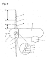
- FIG. 3 1 schematically shows a tidal power station 1 according to the invention.
- This comprises a water turbine 2 with rotor blades 3.1, 3.2, 3.3 fixed in a rotationally fixed manner to a hub 4, which points essentially radially outward for the embodiment shown.
- a drive shaft 5 connects to the hub 4, which connects.
- the other components of the rotating unit 10 and the associated bearing components and the electric generator are not shown in detail. These are typically received in the nacelle 6, which rests on a support structure 7.
- a first radial section 14 is defined, which, as shown by way of example for the rotor blade 3.1, extends from a first radius R 1 to a larger second radius R 2 .
- a second radial section 15 which extends from the third radius R 3 with R 3 > R 2 up to a larger, fourth radius R 4 , the essential contribution to the power coefficient C p for high-speed numbers results with ⁇ > ⁇ S.
- the contributions of the first radial section 14 and the second radial section 15 to the power coefficient C p are in FIG. 4 outlined.
- Shown is a first partially assigned Power coefficient A 1 , which is associated with the first radial section 14. This has a pronounced range with negative power coefficients C p up to a high-speed number ⁇ 2.5. Accordingly, the first radial section 14 brakes the water turbine in the range of small speed numbers ⁇ . In this operating range, the positive contribution by the second area-wise assigned power coefficient A 2 , which reflects the contribution of the second radial section 15, is not sufficient to cause a self-start of the water turbine.
- the total power coefficient C p is determined for larger speed numbers ⁇ substantially by the course of the second regionally associated power coefficient A 2 .
- FIG. 3 shows a magnified illustrated near-profile profile section 11 for the rotor blade 3.2, which falls in the first radial section 14 between the first radius R 1 and the second radius R 2 .
- the selected, bidirectionally flowable profile has an S-beat for the skeleton line, not shown in detail.
- the profile is point-symmetrical to the symmetry point 12.
- the power coefficient can be set to ensure self-start inhibition.
- FIG. 3 the angular position of the chord 13 is shown in outline to the plane of rotation 8, wherein the plane of rotation 8 is defined by the axis of rotation 9 of the rotating unit 10 as surface normal and by the position of the bases of the rotor blades 3.1, 3.2, 3.3 on the hub 4.
- a reduction of the installation angle leads to a profile characteristic for which the profile polar in the inflow angle range of 80 ° - 90 ° has a negative lift coefficient.
Landscapes
- Engineering & Computer Science (AREA)
- Chemical & Material Sciences (AREA)
- Combustion & Propulsion (AREA)
- Mechanical Engineering (AREA)
- General Engineering & Computer Science (AREA)
- Power Engineering (AREA)
- Other Liquid Machine Or Engine Such As Wave Power Use (AREA)
- Hydraulic Turbines (AREA)
- Control Of Water Turbines (AREA)
Description
- Die Erfindung betrifft ein Strömungskraftwerk, insbesondere zur Energiegewinnung aus einer Gezeitenströmung, sowie ein Verfahren zu dessen Betrieb.
- Ohne Dammstrukturen, freistehend in einer Umgebungsströmung arbeitende Strömungskraftwerke sind besonders zur Energiegewinnung aus einer Gezeitenströmung geeignet. Alternativ besteht die Möglichkeit eines Einsatzes in einem Fließgewässer, etwa zur Stromerzeugung an teilweise zurückgebauten Staustufen. Dabei umfassen gattungsgemäße Strömungskraftwerke eine Wasserturbine in Form eines Rotors, der an einer schwimmenden oder sich gegen den Gewässergrund mittels eines Tragwerks abstützenden Maschinengondel umläuft.
- Die freistehende Anlagenkonzeption erlaubt den Aufbau von Gezeitenenergieparks auch an Standorten, die für den Bau umfangreicher Sperrwerke ungeeignet wären. Allerdings müssen derartige Anlagen ohne eine bauliche Vorrichtung für einen trockenfallenden Servicezugang für möglichst lange Wartungsintervalle ausgelegt sein. Des Weiteren ist für den Einsatz im Meer eine möglichst robuste Anlage vorzusehen, um Belastungsspitzen bei stürmischen Wetterbedingungen standzuhalten.
- Ferner müssen Vorkehrungen getroffen werden, um eine Anlage jederzeit sicher anzuhalten und den Anlagenstillstand sichern zu können. Dies ist beispielsweise dann notwendig, wenn die Maschinengondel mit der Wasserturbine zur Ausführung einer Wartung geborgen werden muss. Als eine Lösung wurde vorgeschlagen, die Rotorblätter der Wasserturbine drehbar an einer Nabe zu befestigen und für das Abbremsen der Anlage die Rotorblätter in die Fahnenstellung zu drehen. Zusätzlich werden gattungsgemäße Anlagen typischerweise mit einer Feststellbremse versehen, um unter allen Umständen die Ausführbarkeit eines Rotorstopps sicherstellen zu können.
- Zwar verbessern drehbar angelenkte Rotorblätter das Anlaufverhalten der Wasserturbine, sie führen allerdings zu einer aufwendigen Konstruktion. Dies ist wiederum mit einer erhöhten Ausfallwahrscheinlichkeit der Anlage verbunden. Auch Feststellbremsen für die Wasserturbine oder für weitere Komponenten der umlaufenden Einheit stellen zusätzliche, die Komplexität der Anlage vergrößernde Komponenten dar, für die Ansteuerungen bzw. Energieversorgungssysteme bereitzustellen sind. Dabei ist insbesondere für einen Bremsmechanismus, der nur zeitweilig aktiviert wird, die Problematik maritimen Bewuchses oder der Korrosion insbesondere in einer Salzwasserumgebung gegeben.
- Der Erfindung liegt die Aufgabe zugrunde, die voranstehend genannten Nachteile des Stands der Technik zu überwinden und ein Strömungskraftwerk, insbesondere ein Gezeitenkraftwerk, und ein Verfahren für dessen Betrieb anzugeben, das für eine konstruktiv vereinfachte Anlage ein sicheres Stillsetzen der Wasserturbine gewährleistet.
- Die der Erfindung zugrunde liegende Aufgabe wird durch die Merkmale der unabhängigen Ansprüche gelöst. Vorteilhafte Ausgestaltungen ergeben sich aus den Unteransprüchen.
- Dabei geht die Erfindung von einer Wasserturbine für ein gattungsgemäßes, freistehendes Strömungskraftwerk aus, die in Form eines Rotors mit drehstarren Rotorblättern ausgebildet ist. Dafür sind unterschiedliche Ausgestaltungen denkbar, etwa eine Befestigung der Rotorblätter an einer Nabe, wobei die Rotorblätter sich nach radial außen erstrecken. Dies schließt die Möglichkeit einer Pfeilung der Rotorblätter in Vorwärts- oder Rückwärtsrichtung ein. Als Ausgestaltungsalternative sind ein äußerer Tragring und radial nach innen gerichtete Rotorblätter denkbar. Des Weiteren ist der Rotor mit einem Antriebsstrang verbunden, der wenigstens mittelbar einen elektrischen Generator antreibt. Besonders bevorzugt wird ein Direktantrieb mit einer drehzahlstarren Kopplung der Wasserturbine und des Generatorläufers. Alternativ kann der elektrische Generator mittelbar über ein mechanisches oder hydrodynamisches Getriebe mit der Wasserturbine verbunden sein oder es erfolgt eine indirekte Kraftübertragung mittels eines zwischengeschalteten hydraulischen Kreislaufs.
- Dokument
GB 2461265 - Für das sichere Stillsetzen ist die Wasserturbine einer erfindungsgemäßen Anlage über einen weiten Betriebsbereich nicht selbstanlaufend ausgelegt, wobei die Selbstanlaufhemmung für Schnelllaufzahlen λ unterhalb einer konstruktiv festgelegten Selbstanlauf-Schnelllaufzahl λAS mit λS ≥ 1 auftritt. Dabei ist die Schnelllaufzahl λ als das Verhältnis der Umlaufgeschwindigkeit u, d.h. der Tangentialgeschwindigkeit an den Rotorblattspitzen der Wasserturbine, relativ zur Anströmungsgeschwindigkeit v definiert (λ = u/v), wobei für die Anströmungsgeschwindigkeit von einer über die Rotorfläche energetisch gemittelten Geschwindigkeit der Umgebungsströmung ausgegangen wird.
- Die Selbstanlauf-Schnelllaufzahl λS ist vorliegend als die höchste Schnelllaufzahl λ definiert, für die bei einer Anströmungsgeschwindigkeit v bis zu einer festgelegten, am gewählten Standort theoretisch zu erwartenden Maximal-Anströmungsgeschwindigkeit V max, für die die Anlage ausgelegt ist, die Summe der bremsenden Kräfte in den Lagern der Wasserturbine und der weiteren umlaufenden Komponenten im Antriebsstrang größer ist als das von der Wasserturbine erzeugte Antriebsmoment. Dabei bleibt das im elektrischen Generator erzeugte elektromagnetische Moment unberücksichtigt.
- Besonders bevorzugt wird eine noch höhere Sicherheitsreserve zum Stillsetzen einer erfindungsgemäßen Anlage mit einer Festlegung für die Selbstanlauf-Schnelllaufzahl λS mit λS ≥ 1,5 und besonders bevorzugt λS ≥ 2. Die voranstehend genannten Untergrenzen für die Selbstanlauf-Schnelllaufzahl λS beziehen sich auf eine Anlage, die für eine Schnelllaufzahl λ im Bereich von 3 ≤ λ ≤ 6 leistungsoptimal geführt ist. Für eine hiervon abweichende Anlagenauslegung wird die erfindungsgemäß gewählte Untergrenze für die Selbstanlauf-Schnelllaufzahl λS ausgehend von einer zugeordneten, leistungsoptimalen Schnelllaufzahl λopt durch eine Untergrenze mit λS ≥ λopt/6, bevorzugt λS ≥ λopt/3 und besonders bevorzugt λS ≥ λopt/2 festlegt.
- Erfindungsgemäß ist die Wasserturbine so gestaltet, dass im Bereich kleiner Schnelllaufzahlen λ bis zu einer Null-Durchgangs-Schnelllaufzahl λ0 negative Leistungsbeiwerte C p vorliegen. Zur Festlegung der Selbstanlauf-Schnelllaufzahl λS werden Lagerverluste im Antriebsstrang berücksichtigt, entsprechend ist λS etwas größer als λ0. Für eine besonders vorteilhafte Ausgestaltung der Erfindung ist die Wasserturbine so gestaltet, dass für die Null-Durchgangs-Schnelllaufzahl λ0 die Bedingung λ0 ≥ 1 und besonders bevorzugt λ0 ≥ 1,5 erfüllt ist.
- Ein erfindungsgemäßes Strömungskraftwerk muss beim Anfahren mittels des motorisch betriebenen elektrischen Generators einen weiten Schnelllaufzahlbereich bis zur Selbstanlauf-Schnelllaufzahl λS durchfahren bis die Anlage ausschließlich durch das antreibende Moment der Wasserturbine selbst beschleunigt und bis in den leistungsoptimalen Betriebsbereich fährt. Der ausgedehnte Umlaufgeschwindigkeitsbereich ohne Selbstanlauf stellt demnach sicher, dass auch für die am gewählten Standort zu berücksichtigende Maximal-Anströmungsgeschwindigkeit V max die Wasserturbine nicht unkontrolliert anläuft. Es ist demnach nicht notwendig, eine separate Bremse zum Festsetzen der Wasserturbine zu verwenden, wodurch ein konstruktiv vereinfachtes Anlagenkonzept resultiert.
- Für den Fall, dass eine im Betrieb befindliche Anlage stillgesetzt werden soll, wird der Bremsvorgang dadurch eingeleitet, dass die Umlaufgeschwindigkeit u der Wasserturbine verlangsamt wird und die Schnelllaufzahl λ unter die vorbestimmte Selbstanlauf-Schnelllaufzahl λS sinkt. Hierzu kann ein für einen kurzzeitigen Betrieb konzipiertes Bremssystem verwendet werden. Eine andere Möglichkeit besteht darin, das Bremsmoment über eine Vergrößerung des vom elektrischen Generator erzeugten Generatormoments zu bewirken. Zusätzlich oder alternativ wird die gewünschte Verlangsamung der Umlaufgeschwindigkeit u durch ein kurzfristiges Erhöhen der bremsenden Lagermomente im Antriebsstrang bewirkt. Hierfür kommt im Falle eines Einsatzes von Gleitlagern für die Wasserturbine eine Veränderung der Lagercharakteristik durch einen Eingriff in den Lagerspalt in Frage. Dabei müssen die für das Bremsen ergriffenen Maßnahmen nicht dauerhaft wirken. Sie dienen lediglich dazu, die Schnelllaufzahl λ der Wasserturbine unter die vorgegebene Selbstanlauf-Schnelllaufzahl λS zu bringen. Die weitere Bremsphase bis zum endgültigen Stillstand ergibt sich dann automatisch aufgrund der Nicht-Selbstanlaufcharakteristik der Wasserturbine.
- Besonders bevorzugt wird eine rotorförmig ausgebildete Wasserturbine verwendet, deren Rotorblätter bezüglich des Einbauwinkel- und des Profilverlaufs so gestaltet sind, dass die erfindungsgemäße Festlegung für die Selbstanlauf-Schnelllaufzahl λS mit λS ≥ 1 erzielt wird. Dabei wird für eine bevorzugte Ausgestaltung der Erfindung wenigstens ein lokal begrenzter Teilabschnitt der Längserstreckung der Rotorblätter zur Sicherstellung der ausgedehnten Selbstanlaufhemmung ausgelegt. Hierfür kommen insbesondere die im Langsamlauf stärker gewichteten, radial inneren Abschnitte in Frage, während radial äußere Abschnitte insbesondere für einen vorteilhaften Schnelllauf im Bereich der optimalen Schnelllaufzahlen λopt ausgelegt werden. Neben dem ersten Radialabschnitt des Rotorblatts zur Anpassung im Bereich kleiner Schnelllaufzahlen mit λ ≤ λS liegt demnach wenigstens ein zweiter Radialabschnitt vor, für den der Profilverlauf und der Einbauwinkel zur Erzielung eines möglichst hohen Wirkungsgrads im Bereich λ > λS gewählt sind.
- Für eine Weitergestaltung der Erfindung wird die ausgedehnte Selbstanlaufhemmung der Wasserturbine mit einer bidirektionalen Anströmungscharakteristik kombiniert. Hierzu werden insbesondere punktsymmetrische Profile mit Wölbung, demnach Profile mit einer S-Schlagförmigen Skelettlinie verwendet. Diese können vorteilhaft so gewählt sein, dass im Langsamlauf mit λ ≤ λ0 die gewünschten negativen Leistungsbeiwerte Cp ≤ 0 resultieren und Schnelllaufzahlen λ im Betriebsbereich um λopt für eine Anströmung aus zwei entgegengesetzt gerichteten Hauptanströmungsrichtungen zu einem akzeptablen Wirkungsgrad führen.
- Nachfolgend wird die Erfindung anhand von Ausführungsbeispielen und in Verbindung mit Figurendarstellungen genauer erläutert. In diesen ist im Einzelnen Folgendes dargestellt:
- Figur 1
- zeigt einen charakteristischen Verlauf des Leistungsbeiwerts C p in Abhängigkeit der Schnelllaufzahl λ für ein erfindungsgemäßes Strömungskraftwerk.
- Figur 2
- zeigt für eine Anlage mit einer Leistungsbeiwert-Charakteristik gemäß
Figur 1 die von der Wasserturbine erzeugte Antriebsleistung P in Abhängigkeit der Anströmungsgeschwindigkeit V für unterschiedlich gewählte Schnelllaufzahlen λ sowie die geschwindigkeitsabhängige, bremsende Verlustleistung P r in den Lagern. - Figur 3
- zeigt eine Ausführungsvariante der Erfindung mit einer lokal begrenzten Anpassung der Rotorblätter der Wasserturbine zur Realisierung einer ausgedehnten Selbstanlaufhemmung.
- Figur 4
- zeigt den Verlauf des bereichsweise zugeordneten Leistungsbeiwerts für die in
Figur 3 dargestellten Radialabschnitte der Wasserturbine. -
Figur 1 zeigt für ein bevorzugtes Ausführungsbeispiel der Erfindung den Verlauf des Leistungsbeiwerts C p der Wasserturbine in Abhängigkeit der Schnelllaufzahl λ. Gewählt ist eine Anlagenauslegung mit einer leistungsoptimalen Schnelllaufzahl λopt = 4. Zur Sicherstellung einer ausgedehnten Selbstanlaufhemmung ist die Wasserturbine so gestaltet, dass für kleine Schnelllaufzahlen λ der Leistungsbeiwert Cp kleiner als null ist. Der Bereich mit C p ≤ 0 reicht bis zur Null-Durchgangs-Schnelllaufzahl λ0, wobei λ0 für das vorliegende bevorzugte Ausgestaltungsbeispiel mit λ0 > 2 gewählt ist. Des Weiteren tritt bis zur Selbstanlauf-Schnelllaufzahl λS, die vorliegend mit λS > 2 gewählt ist, die Bedingung auf, dass für alle Anströmungsgeschwindigkeiten v, für die die Anlage ausgelegt ist, das auf die umlaufende Einheit wirkende, bremsende Moment größer ist als das von der Wasserturbine erzeugte antreibende Moment. Dies wird nachfolgend anhand vonFigur 2 verdeutlicht. Dargestellt ist die von der Wasserturbine erzeugte Antriebsleistung P in Abhängigkeit der Anströmungsgeschwindigkeit v. Dabei ist für eine leistungsoptimale Schnelllaufzahl λopt, die für das vorliegende Ausführungsbeispiel bei λ = 4 liegt, ein leistungsoptimaler Anlagenbetrieb gegeben. In diesem Bereich wird im Normalbetrieb die Anlage geführt, bis die Nennleistung P n erreicht wird und eine Leistungsabregelung erfolgt. Zu diesem Zweck kann eine Leistungsbegrenzung durch den Betrieb im Schnelllaufbereich mit λ > λopt ausgeführt werden. - Ferner zeigt
Figur 2 den Verlauf der in den Lagern der umlaufenden Einheit erzeugten Verlustleistung P r, die mit zunehmender Anströmungsgeschwindigkeit v ansteigt. Dabei ist die Verlustleistung P r zur Verdeutlichung übertrieben dargestellt, da die typischerweise auftretenden Lagerverluste im Bereich von < 2 % bezogen auf die Nennleistung P n liegen. - Für kleine Schnelllaufzahlen mit λ ≤ 2 liegen für die bevorzugte Ausgestaltung gemäß
Figur 1 negative Leistungsbeiwerte C p vor. Der Bereich der Selbstanlaufhemmung reicht für das vorliegende Ausführungsbeispiel unter Annahme einer zur Verdeutlichung übertrieben dargestellten Verlustleistung P r bis zu einer Schnelllaufzahl von λ = 2,5, die der Selbstanlauf-Schnelllaufzahl λS entspricht. Für diese gilt, dass für alle Anströmungsgeschwindigkeiten v unterhalb der theoretisch zu erwartenden Maximal-Anströmungsgeschwindigkeit v max die Bedingung erfüllt ist, dass die von der Wasserturbine erzeugte Antriebsleistung P nicht größer als die Verlustleistung P r in den Lagern ist. -
Figur 3 zeigt schematisch vereinfacht ein erfindungsgemäßes Gezeitenkraftwerk 1. Dies umfasst eine Wasserturbine 2 mit drehstarr an einer Nabe 4 befestigten Rotorblättern 3.1, 3.2, 3.3, die für die dargestellte Ausgestaltung im Wesentlichen nach radial außen weisen. An die Nabe 4 schließt eine Antriebswelle 5 an. Die weiteren Komponenten der umlaufenden Einheit 10 sowie die zugeordneten Lagerkomponenten und der elektrische Generator sind im Einzelnen nicht dargestellt. Diese werden typischerweise in der Maschinengondel 6 aufgenommen, die auf einer Stützstruktur 7 ruht. - Für die in
Figur 3 dargestellte Ausführungsvariante der Erfindung sind die radial inneren Bereiche der Rotorblätter 3.1, 3.2, 3.3 für die erfindungsgemäß gewählte Anlaufhemmung verantwortlich. Hierzu wird ein erster Radialabschnitt 14 festgelegt, der, wie exemplarisch für das Rotorblatt 3.1 dargestellt, von einem ersten Radius R 1 bis zu einem größeren zweiten Radius R 2 reicht. Für einen zweiten Radialabschnitt 15, der vom dritten Radius R 3 mit R 3 > R 2 bis zu einem größeren, vierten Radius R 4 reicht, resultiert der wesentliche Beitrag zum Leistungsbeiwert C p für Schnelllaufzahlen mit λ > λS. Die Beiträge des ersten Radialabschnitts 14 und des zweiten Radialabschnitts 15 zum Leistungsbeiwert C p sind inFigur 4 skizziert. Dargestellt ist ein erster bereichsweise zugeordneter Leistungsbeiwert A 1, der dem ersten Radialabschnitt 14 zugeordnet ist. Dieser weist einen ausgeprägten Bereich mit negativen Leistungsbeiwerten C p bis zu einer Schnelllaufzahl λ = 2,5 auf. Demnach bremst der erste Radialabschnitt 14 die Wasserturbine im Bereich kleiner Schnelllaufzahlen λ. In diesem Betriebsbereich reicht der positive Beitrag durch den zweiten bereichsweise zugeordneten Leistungsbeiwert A 2, der den Beitrag des zweiten Radialabschnitts 15 widerspiegelt, nicht aus, um einen Selbstanlauf der Wasserturbine zu bewirken. Der gesamte Leistungsbeiwert C p wird für größere Schnelllaufzahlen λ im Wesentlichen durch den Verlauf des zweiten bereichsweise zugeordneten Leistungsbeiwerts A 2 bestimmt. -
Figur 3 zeigt einen vergrößert dargestellten nabennahen Profilschnitt 11 für das Rotorblatt 3.2, der in den ersten Radialabschnitt 14 zwischen dem ersten Radius R 1 und dem zweiten Radius R 2 fällt. Das gewählte, bidirektional anströmbare Profil weist einen S-Schlag für die im Einzelnen nicht dargestellte Skelettlinie auf. Dabei ist das Profil punktsymmetrisch zum Symmetriepunkt 12. Durch die Wahl des Profil- und Einbauwinkelverlaufs kann die Leistungsbeiwertcharakteristik zur Sicherstellung der Selbstanlaufhemmung festgelegt werden. InFigur 3 ist die Winkelstellung der Profilsehne 13 zur Rotationsebene 8 skizziert dargestellt, wobei die Rotationsebene 8 durch die Rotationsachse 9 der umlaufenden Einheit 10 als Flächennormale und durch die Lage der Fußpunkte der Rotorblätter 3.1, 3.2, 3.3 an der Nabe 4 festgelegt ist. Dabei führt eine Verringerung des Einbauwinkels zu einer Profilcharakteristik, für die die Profilpolare im Anströmungswinkelbereich von 80°- 90° einen negativen Auftriebsbeiwert aufweist. - Weitere Ausführungsvarianten der Erfindung ergeben sich aus den nachfolgenden Schutzansprüchen.
-
- 1
- Gezeitenkraftwerk
- 2
- Wasserturbine
- 3.1, 3.2, 3.3
- Rotorblätter
- 4
- Nabe
- 5
- Antriebswelle
- 6
- Maschinengondel
- 7
- Stützstruktur
- 8
- Rotationsebene
- 9
- Rotationsachse
- 10
- umlaufende Einheit
- 11
- Profilschnitt
- 12
- Symmetriepunkt
- 13
- Profilsehne
- 14
- erster Radialabschnitt
- 15
- zweiter Radialabschnitt
- A1
- erster bereichsweise zugeordneter Leistungsbeiwert
- A2
- zweiter bereichsweise zugeordneter Leistungsbeiwert
- u
- Umlaufgeschwindigkeit
- V
- Anströmungsgeschwindigkeit
- V max
- maximale Anströmungsgeschwindigkeit
- C p
- Leistungsbeiwert
- λ
- Schnelllaufzahl
- λopt
- leistungsoptimale Schnelllaufzahl
- λS
- Selbstanlauf-Schnelllaufzahl
- λ0
- Null-Durchgangs-Schnelllaufzahl
- P
- Antriebsleistung
- P n
- Nennleistung
- P r
- Verlustleistung
Claims (7)
- Strömungskraftwerk, umfassend1.1 eine Wasserturbine (2) mit drehstarren Rotorblättern (3.1, 3.2, 3.3);1.2 einen mit der Wasserturbine (2) verbundenen Antriebsstrang, der wenigstens mittelbar einen elektrischen Generator antreibt;
dadurch gekennzeichnet, dass1.3 bei Anströmungsgeschwindigkeiten v, für die das Strömungskraftwerk ausgelegt ist, die Wasserturbine (2) für Schnelllaufzahlen λ unterhalb einer vorbestimmten Selbstanlauf-Schnelllaufzahl λS mit λS ≥ 1 nicht selbstanlaufend ausgebildet ist; und1.4 die Wasserturbine (2) bis zu einer Null-Durchgangs-Schnelllaufzahl λ0, die kleiner als die Selbstanlauf-Schnelllaufzahl λS ist, einen negativen Leistungsbeiwert Cp aufweist. - Strömungskraftwerk nach Anspruch 1, dadurch gekennzeichnet, dass für die Selbstanlauf-Schnelllaufzahl λS ≥ 1,5 und bevorzugt λS ≥ 2 gilt.
- Strömungskraftwerk nach einem der Ansprüche 1 oder 2, dadurch gekennzeichnet, dass ausgehend von einer leistungsoptimalen Schnelllaufzahl λopt der Wasserturbine (2) für die Selbstanlauf-Schnelllaufzahl λS ≥ λopt/6, bevorzugt λS ≥ λopt/3 und besonders bevorzugt λS ≥ λopt/2 gilt.
- Strömungskraftwerk nach Anspruch 1, dadurch gekennzeichnet, dass für die Null-Durchgangs-Schnelllaufzahl λ0 ≥ 1 und bevorzugt λ0 ≥ 1,5 gilt.
- Strömungskraftwerk nach einem der vorausgehenden Ansprüche, dadurch gekennzeichnet, dass die Rotorblätter (3.1, 3.2, 3.3) der Wasserturbine (2) jeweils einen ersten Radialabschnitt (14) und einen zweiten Radialabschnitt (15) umfassen, wobei der Profilverlauf und der Einbauwinkelverlauf für den ersten Radialabschnitt (14) an Schnelllaufzahlen λ unterhalb der Selbstanlauf-Schnelllaufzahl und für den zweiten Radialbschnitt (15) an Schnelllaufzahlen λ oberhalb der Selbstanlauf-Schnelllaufzahl λS angepasst sind.
- Strömungskraftwerk nach einem der vorausgehenden Ansprüche, dadurch gekennzeichnet, dass die Wasserturbine (2) bidirektional anströmbar ist.
- Strömungskraftwerk nach Anspruch 6, dadurch gekennzeichnet, dass die Rotorblätter (3.1, 3.2, 3.3) der Wasserturbine (2) wenigstens über einen Teil ihrer Radialerstreckung ein gewölbtes, punktsymmetrisches Profil aufweisen.
Applications Claiming Priority (2)
| Application Number | Priority Date | Filing Date | Title |
|---|---|---|---|
| DE102010015534A DE102010015534A1 (de) | 2010-04-16 | 2010-04-16 | Strömungskraftwerk und Verfahren für dessen Betrieb |
| PCT/EP2011/000842 WO2011141074A2 (de) | 2010-04-16 | 2011-02-22 | Strömungskraftwerk und verfahren zu dessen betrieb |
Publications (2)
| Publication Number | Publication Date |
|---|---|
| EP2521856A2 EP2521856A2 (de) | 2012-11-14 |
| EP2521856B1 true EP2521856B1 (de) | 2014-10-01 |
Family
ID=44625294
Family Applications (1)
| Application Number | Title | Priority Date | Filing Date |
|---|---|---|---|
| EP11706472.5A Not-in-force EP2521856B1 (de) | 2010-04-16 | 2011-02-22 | Strömungskraftwerk und verfahren zu dessen betrieb |
Country Status (7)
| Country | Link |
|---|---|
| US (1) | US8847418B2 (de) |
| EP (1) | EP2521856B1 (de) |
| JP (1) | JP2013525660A (de) |
| KR (1) | KR20130059319A (de) |
| CA (1) | CA2793149A1 (de) |
| DE (1) | DE102010015534A1 (de) |
| WO (1) | WO2011141074A2 (de) |
Families Citing this family (2)
| Publication number | Priority date | Publication date | Assignee | Title |
|---|---|---|---|---|
| GB2495442B (en) * | 2010-12-30 | 2014-11-05 | Cameron Int Corp | System for the control of water level |
| DE102012224188A1 (de) * | 2012-12-21 | 2014-06-26 | Wobben Properties Gmbh | Verfahren zur Steuerung eines Wasserschütz-Antriebs für ein Wasserschütz mit einer elektrischen Maschine, Betriebsschaltung, Wasserschütz-Antrieb und Wasserkraftanlage |
Family Cites Families (21)
| Publication number | Priority date | Publication date | Assignee | Title |
|---|---|---|---|---|
| DE2418624C2 (de) | 1974-04-18 | 1981-12-10 | Pintsch Bamag Antriebs- Und Verkehrstechnik Gmbh, 4220 Dinslaken | Seezeichen, insbesondere Boje, mit elektrischer Lichtquelle |
| US5946909A (en) * | 1997-05-23 | 1999-09-07 | Swort International, Inc. | Floating turbine system for generating power |
| US6877968B2 (en) * | 2002-11-27 | 2005-04-12 | The Salmon River Project Limited | Low head water turbine |
| US6824353B2 (en) * | 2002-12-19 | 2004-11-30 | Wen-Pin Lin | Water turbine |
| BRPI0507012A (pt) * | 2004-01-21 | 2007-06-05 | Harvest Wind Energy Corp | turbina e pá de turbina |
| ITVA20040055A1 (it) * | 2004-11-23 | 2005-02-23 | St Microelectronics Srl | Metodo e circuito di controllo di un impianto di generazione di energia elettrica |
| US7357701B2 (en) * | 2005-04-07 | 2008-04-15 | Dan Gautier | Water driven rotary tool |
| US7500907B2 (en) * | 2005-04-07 | 2009-03-10 | Jose Gentilcore | Water driven motor |
| TW200726908A (en) * | 2005-10-04 | 2007-07-16 | Arthur Benjamin O Connor | Wind turbine |
| US8174136B2 (en) * | 2006-04-26 | 2012-05-08 | Alliance For Sustainable Energy, Llc | Adaptive pitch control for variable speed wind turbines |
| AU2007249992A1 (en) * | 2006-05-10 | 2007-11-22 | Viryd Technologies Inc. | Fluid energy converter |
| WO2008045662A2 (en) * | 2006-10-10 | 2008-04-17 | Adaptide, Inc. | Adaptive tidal current power extraction device |
| US8147201B2 (en) * | 2007-08-10 | 2012-04-03 | Verdant Power Inc. | Kinetic hydro power triangular blade hub |
| KR101542873B1 (ko) | 2007-11-16 | 2015-08-07 | 엘리멘털 에너지 테크널러지스 리미티드 | 동력발생장치 조립체, 추진 또는 펌프장치 및 발전장치 설비 |
| DE102007061185B4 (de) * | 2007-12-17 | 2010-11-11 | Voith Patent Gmbh | Tauchende Energieerzeugungsanlage, angetrieben durch eine Wasserströmung |
| AU2008338257B2 (en) | 2007-12-19 | 2014-03-27 | Neville Alan Smith | Apparatus for extracting energy from flowing water |
| RU2502890C2 (ru) * | 2008-01-08 | 2013-12-27 | Ричард Артур Генри РЭЙНОЛДС | Турбинная установка и электростанция |
| DE102008023050A1 (de) * | 2008-05-09 | 2009-11-12 | Voith Patent Gmbh | Verfahren und Vorrichtung zum Betrieb eines Gleitlagers |
| GB2461265A (en) | 2008-06-23 | 2009-12-30 | Tidal Energy Ltd | Tidal turbine with limited axial thrust |
| US20100060001A1 (en) * | 2008-07-31 | 2010-03-11 | Mariah Power, Inc. | Wind turbine safety system and methods |
| DE102008053732B8 (de) * | 2008-10-29 | 2013-10-02 | Voith Patent Gmbh | Verfahren und Vorrichtung für die Leistungsregelung eines Unterwasserkraftwerks |
-
2010
- 2010-04-16 DE DE102010015534A patent/DE102010015534A1/de not_active Withdrawn
-
2011
- 2011-02-22 US US13/580,804 patent/US8847418B2/en not_active Expired - Fee Related
- 2011-02-22 JP JP2013504140A patent/JP2013525660A/ja active Pending
- 2011-02-22 KR KR1020127024451A patent/KR20130059319A/ko not_active Withdrawn
- 2011-02-22 CA CA2793149A patent/CA2793149A1/en not_active Abandoned
- 2011-02-22 WO PCT/EP2011/000842 patent/WO2011141074A2/de not_active Ceased
- 2011-02-22 EP EP11706472.5A patent/EP2521856B1/de not_active Not-in-force
Also Published As
| Publication number | Publication date |
|---|---|
| CA2793149A1 (en) | 2011-11-17 |
| US20130049362A1 (en) | 2013-02-28 |
| DE102010015534A1 (de) | 2011-10-20 |
| US8847418B2 (en) | 2014-09-30 |
| EP2521856A2 (de) | 2012-11-14 |
| WO2011141074A3 (de) | 2012-04-12 |
| KR20130059319A (ko) | 2013-06-05 |
| WO2011141074A2 (de) | 2011-11-17 |
| JP2013525660A (ja) | 2013-06-20 |
Similar Documents
| Publication | Publication Date | Title |
|---|---|---|
| EP1255931B1 (de) | Windenergieanlage mit zwei hintereinander angeordneten rotoren | |
| EP2467600B1 (de) | Windkraftanlage und verfahren zur betriebssteuerung einer windkraftanlage | |
| EP2655874B1 (de) | Windkraft-rotor und verfahren zur energieerzeugung damit | |
| EP2729695B1 (de) | Strömungskraftwerk und verfahren für dessen betrieb | |
| EP1394406A3 (de) | Getriebelose Windturbine mit vielpoligem Synchrongenerator | |
| EP2406877A1 (de) | Verfahren und vorrichtung zum bremsen eines unterwasserkraftwerks | |
| DE102004041281B4 (de) | Verfahren für die Gewinnung elektrischer Energie aus Windenergie und ein Vertikalrotor für ein solches Verfahren | |
| DE102012013896A1 (de) | Windenergieanlage | |
| DE19644705A1 (de) | Vorrichtung zur Verstellung von Rotorblättern | |
| DE202011000798U1 (de) | Kanal als Pumpspeicherkraftwerk | |
| DE102008051370A1 (de) | Unterwasserkraftwerk mit passiver Leistungsregelung | |
| EP2522847B1 (de) | Strömungskraftwerkspark und Verfahren für dessen Erstellung | |
| EP2425124B1 (de) | Unterwasserkraftwerk mit einer bidirektional anströmbaren, gleichsinnig umlaufenden wasserturbine | |
| DE202021104898U1 (de) | Laufrad mit einer einstellbaren Anzahl von Schaufeln | |
| DE102010015534A1 (de) | Strömungskraftwerk und Verfahren für dessen Betrieb | |
| AT505351B1 (de) | Windrad | |
| EP2707597B1 (de) | Strömungskraftwerk und verfahren für dessen betrieb | |
| EP1387954B1 (de) | Vertikalachs-windturbine | |
| DE102009051117A1 (de) | Horizontalläufer-Turbine mit passiver Gierwinkel-Einstellvorrichtung | |
| EP2636892A2 (de) | Windkraftanlage und Verfahren zum Erzeugen von rotatorischer Energie durch Wind | |
| DE102018113760A1 (de) | Rotorlagergehäuse und Windenergieanlage mit Rotorlagergehäuse | |
| DE102023003821B3 (de) | Windkraftanlage zur Erzeugung von elektr. Energie, gekennzeichnet durch vertikal umlaufende Rotoren auf einer nicht kreisrunden Bahn | |
| EP2954201B1 (de) | Wind- oder wasserkraftmaschine sowie kraftmaschinenpark | |
| DE3017357A1 (de) | Hydrodynamischer energiewandler mit integrierter leistungsregelung | |
| DE102006050498B3 (de) | Windkraftanlage: Einarm-Flügel mit 3flg.-Propeller Rotor-Doppelkopf-Anlage |
Legal Events
| Date | Code | Title | Description |
|---|---|---|---|
| PUAI | Public reference made under article 153(3) epc to a published international application that has entered the european phase |
Free format text: ORIGINAL CODE: 0009012 |
|
| 17P | Request for examination filed |
Effective date: 20120802 |
|
| AK | Designated contracting states |
Kind code of ref document: A2 Designated state(s): AL AT BE BG CH CY CZ DE DK EE ES FI FR GB GR HR HU IE IS IT LI LT LU LV MC MK MT NL NO PL PT RO RS SE SI SK SM TR |
|
| RIN1 | Information on inventor provided before grant (corrected) |
Inventor name: BISKUP, FRANK Inventor name: WEILEPP, JOCHEN Inventor name: ARLITT, RAPHAEL |
|
| DAX | Request for extension of the european patent (deleted) | ||
| GRAP | Despatch of communication of intention to grant a patent |
Free format text: ORIGINAL CODE: EPIDOSNIGR1 |
|
| GRAS | Grant fee paid |
Free format text: ORIGINAL CODE: EPIDOSNIGR3 |
|
| GRAA | (expected) grant |
Free format text: ORIGINAL CODE: 0009210 |
|
| INTG | Intention to grant announced |
Effective date: 20140804 |
|
| AK | Designated contracting states |
Kind code of ref document: B1 Designated state(s): AL AT BE BG CH CY CZ DE DK EE ES FI FR GB GR HR HU IE IS IT LI LT LU LV MC MK MT NL NO PL PT RO RS SE SI SK SM TR |
|
| REG | Reference to a national code |
Ref country code: GB Ref legal event code: FG4D Free format text: NOT ENGLISH |
|
| REG | Reference to a national code |
Ref country code: CH Ref legal event code: EP Ref country code: AT Ref legal event code: REF Ref document number: 689673 Country of ref document: AT Kind code of ref document: T Effective date: 20141015 |
|
| REG | Reference to a national code |
Ref country code: IE Ref legal event code: FG4D Free format text: LANGUAGE OF EP DOCUMENT: GERMAN |
|
| REG | Reference to a national code |
Ref country code: DE Ref legal event code: R096 Ref document number: 502011004517 Country of ref document: DE Effective date: 20141113 |
|
| REG | Reference to a national code |
Ref country code: NO Ref legal event code: T2 Effective date: 20141001 |
|
| REG | Reference to a national code |
Ref country code: FR Ref legal event code: PLFP Year of fee payment: 5 |
|
| REG | Reference to a national code |
Ref country code: NL Ref legal event code: VDEP Effective date: 20141001 |
|
| REG | Reference to a national code |
Ref country code: LT Ref legal event code: MG4D |
|
| PG25 | Lapsed in a contracting state [announced via postgrant information from national office to epo] |
Ref country code: NL Free format text: LAPSE BECAUSE OF FAILURE TO SUBMIT A TRANSLATION OF THE DESCRIPTION OR TO PAY THE FEE WITHIN THE PRESCRIBED TIME-LIMIT Effective date: 20141001 |
|
| PG25 | Lapsed in a contracting state [announced via postgrant information from national office to epo] |
Ref country code: CZ Free format text: LAPSE BECAUSE OF FAILURE TO SUBMIT A TRANSLATION OF THE DESCRIPTION OR TO PAY THE FEE WITHIN THE PRESCRIBED TIME-LIMIT Effective date: 20141001 Ref country code: FI Free format text: LAPSE BECAUSE OF FAILURE TO SUBMIT A TRANSLATION OF THE DESCRIPTION OR TO PAY THE FEE WITHIN THE PRESCRIBED TIME-LIMIT Effective date: 20141001 Ref country code: PT Free format text: LAPSE BECAUSE OF FAILURE TO SUBMIT A TRANSLATION OF THE DESCRIPTION OR TO PAY THE FEE WITHIN THE PRESCRIBED TIME-LIMIT Effective date: 20150202 Ref country code: IS Free format text: LAPSE BECAUSE OF FAILURE TO SUBMIT A TRANSLATION OF THE DESCRIPTION OR TO PAY THE FEE WITHIN THE PRESCRIBED TIME-LIMIT Effective date: 20150201 Ref country code: ES Free format text: LAPSE BECAUSE OF FAILURE TO SUBMIT A TRANSLATION OF THE DESCRIPTION OR TO PAY THE FEE WITHIN THE PRESCRIBED TIME-LIMIT Effective date: 20141001 Ref country code: LT Free format text: LAPSE BECAUSE OF FAILURE TO SUBMIT A TRANSLATION OF THE DESCRIPTION OR TO PAY THE FEE WITHIN THE PRESCRIBED TIME-LIMIT Effective date: 20141001 |
|
| PGFP | Annual fee paid to national office [announced via postgrant information from national office to epo] |
Ref country code: NO Payment date: 20150212 Year of fee payment: 5 Ref country code: DE Payment date: 20150219 Year of fee payment: 5 |
|
| PG25 | Lapsed in a contracting state [announced via postgrant information from national office to epo] |
Ref country code: SE Free format text: LAPSE BECAUSE OF FAILURE TO SUBMIT A TRANSLATION OF THE DESCRIPTION OR TO PAY THE FEE WITHIN THE PRESCRIBED TIME-LIMIT Effective date: 20141001 Ref country code: CY Free format text: LAPSE BECAUSE OF FAILURE TO SUBMIT A TRANSLATION OF THE DESCRIPTION OR TO PAY THE FEE WITHIN THE PRESCRIBED TIME-LIMIT Effective date: 20141001 Ref country code: RS Free format text: LAPSE BECAUSE OF FAILURE TO SUBMIT A TRANSLATION OF THE DESCRIPTION OR TO PAY THE FEE WITHIN THE PRESCRIBED TIME-LIMIT Effective date: 20141001 Ref country code: GR Free format text: LAPSE BECAUSE OF FAILURE TO SUBMIT A TRANSLATION OF THE DESCRIPTION OR TO PAY THE FEE WITHIN THE PRESCRIBED TIME-LIMIT Effective date: 20150102 Ref country code: HR Free format text: LAPSE BECAUSE OF FAILURE TO SUBMIT A TRANSLATION OF THE DESCRIPTION OR TO PAY THE FEE WITHIN THE PRESCRIBED TIME-LIMIT Effective date: 20141001 Ref country code: LV Free format text: LAPSE BECAUSE OF FAILURE TO SUBMIT A TRANSLATION OF THE DESCRIPTION OR TO PAY THE FEE WITHIN THE PRESCRIBED TIME-LIMIT Effective date: 20141001 Ref country code: PL Free format text: LAPSE BECAUSE OF FAILURE TO SUBMIT A TRANSLATION OF THE DESCRIPTION OR TO PAY THE FEE WITHIN THE PRESCRIBED TIME-LIMIT Effective date: 20141001 |
|
| PGFP | Annual fee paid to national office [announced via postgrant information from national office to epo] |
Ref country code: GB Payment date: 20150218 Year of fee payment: 5 Ref country code: FR Payment date: 20150219 Year of fee payment: 5 |
|
| PG25 | Lapsed in a contracting state [announced via postgrant information from national office to epo] |
Ref country code: BE Free format text: LAPSE BECAUSE OF NON-PAYMENT OF DUE FEES Effective date: 20150228 |
|
| REG | Reference to a national code |
Ref country code: DE Ref legal event code: R097 Ref document number: 502011004517 Country of ref document: DE |
|
| PG25 | Lapsed in a contracting state [announced via postgrant information from national office to epo] |
Ref country code: SK Free format text: LAPSE BECAUSE OF FAILURE TO SUBMIT A TRANSLATION OF THE DESCRIPTION OR TO PAY THE FEE WITHIN THE PRESCRIBED TIME-LIMIT Effective date: 20141001 Ref country code: DK Free format text: LAPSE BECAUSE OF FAILURE TO SUBMIT A TRANSLATION OF THE DESCRIPTION OR TO PAY THE FEE WITHIN THE PRESCRIBED TIME-LIMIT Effective date: 20141001 Ref country code: RO Free format text: LAPSE BECAUSE OF FAILURE TO SUBMIT A TRANSLATION OF THE DESCRIPTION OR TO PAY THE FEE WITHIN THE PRESCRIBED TIME-LIMIT Effective date: 20141001 Ref country code: EE Free format text: LAPSE BECAUSE OF FAILURE TO SUBMIT A TRANSLATION OF THE DESCRIPTION OR TO PAY THE FEE WITHIN THE PRESCRIBED TIME-LIMIT Effective date: 20141001 |
|
| PLBE | No opposition filed within time limit |
Free format text: ORIGINAL CODE: 0009261 |
|
| STAA | Information on the status of an ep patent application or granted ep patent |
Free format text: STATUS: NO OPPOSITION FILED WITHIN TIME LIMIT |
|
| PG25 | Lapsed in a contracting state [announced via postgrant information from national office to epo] |
Ref country code: IT Free format text: LAPSE BECAUSE OF FAILURE TO SUBMIT A TRANSLATION OF THE DESCRIPTION OR TO PAY THE FEE WITHIN THE PRESCRIBED TIME-LIMIT Effective date: 20141001 |
|
| 26N | No opposition filed |
Effective date: 20150702 |
|
| PG25 | Lapsed in a contracting state [announced via postgrant information from national office to epo] |
Ref country code: LU Free format text: LAPSE BECAUSE OF FAILURE TO SUBMIT A TRANSLATION OF THE DESCRIPTION OR TO PAY THE FEE WITHIN THE PRESCRIBED TIME-LIMIT Effective date: 20150222 |
|
| REG | Reference to a national code |
Ref country code: CH Ref legal event code: PL |
|
| PG25 | Lapsed in a contracting state [announced via postgrant information from national office to epo] |
Ref country code: MC Free format text: LAPSE BECAUSE OF FAILURE TO SUBMIT A TRANSLATION OF THE DESCRIPTION OR TO PAY THE FEE WITHIN THE PRESCRIBED TIME-LIMIT Effective date: 20141001 Ref country code: LI Free format text: LAPSE BECAUSE OF NON-PAYMENT OF DUE FEES Effective date: 20150228 Ref country code: CH Free format text: LAPSE BECAUSE OF NON-PAYMENT OF DUE FEES Effective date: 20150228 |
|
| REG | Reference to a national code |
Ref country code: IE Ref legal event code: MM4A |
|
| PG25 | Lapsed in a contracting state [announced via postgrant information from national office to epo] |
Ref country code: IE Free format text: LAPSE BECAUSE OF NON-PAYMENT OF DUE FEES Effective date: 20150222 |
|
| PG25 | Lapsed in a contracting state [announced via postgrant information from national office to epo] |
Ref country code: SI Free format text: LAPSE BECAUSE OF FAILURE TO SUBMIT A TRANSLATION OF THE DESCRIPTION OR TO PAY THE FEE WITHIN THE PRESCRIBED TIME-LIMIT Effective date: 20141001 |
|
| REG | Reference to a national code |
Ref country code: DE Ref legal event code: R119 Ref document number: 502011004517 Country of ref document: DE |
|
| REG | Reference to a national code |
Ref country code: NO Ref legal event code: MMEP |
|
| GBPC | Gb: european patent ceased through non-payment of renewal fee |
Effective date: 20160222 |
|
| PG25 | Lapsed in a contracting state [announced via postgrant information from national office to epo] |
Ref country code: NO Free format text: LAPSE BECAUSE OF NON-PAYMENT OF DUE FEES Effective date: 20160229 |
|
| REG | Reference to a national code |
Ref country code: FR Ref legal event code: ST Effective date: 20161028 |
|
| PG25 | Lapsed in a contracting state [announced via postgrant information from national office to epo] |
Ref country code: MT Free format text: LAPSE BECAUSE OF FAILURE TO SUBMIT A TRANSLATION OF THE DESCRIPTION OR TO PAY THE FEE WITHIN THE PRESCRIBED TIME-LIMIT Effective date: 20141001 |
|
| PG25 | Lapsed in a contracting state [announced via postgrant information from national office to epo] |
Ref country code: DE Free format text: LAPSE BECAUSE OF NON-PAYMENT OF DUE FEES Effective date: 20160901 Ref country code: FR Free format text: LAPSE BECAUSE OF NON-PAYMENT OF DUE FEES Effective date: 20160229 Ref country code: GB Free format text: LAPSE BECAUSE OF NON-PAYMENT OF DUE FEES Effective date: 20160222 |
|
| REG | Reference to a national code |
Ref country code: AT Ref legal event code: MM01 Ref document number: 689673 Country of ref document: AT Kind code of ref document: T Effective date: 20160222 |
|
| PG25 | Lapsed in a contracting state [announced via postgrant information from national office to epo] |
Ref country code: HU Free format text: LAPSE BECAUSE OF FAILURE TO SUBMIT A TRANSLATION OF THE DESCRIPTION OR TO PAY THE FEE WITHIN THE PRESCRIBED TIME-LIMIT; INVALID AB INITIO Effective date: 20110222 Ref country code: BG Free format text: LAPSE BECAUSE OF FAILURE TO SUBMIT A TRANSLATION OF THE DESCRIPTION OR TO PAY THE FEE WITHIN THE PRESCRIBED TIME-LIMIT Effective date: 20141001 Ref country code: SM Free format text: LAPSE BECAUSE OF FAILURE TO SUBMIT A TRANSLATION OF THE DESCRIPTION OR TO PAY THE FEE WITHIN THE PRESCRIBED TIME-LIMIT Effective date: 20141001 Ref country code: AT Free format text: LAPSE BECAUSE OF NON-PAYMENT OF DUE FEES Effective date: 20160222 |
|
| PG25 | Lapsed in a contracting state [announced via postgrant information from national office to epo] |
Ref country code: TR Free format text: LAPSE BECAUSE OF FAILURE TO SUBMIT A TRANSLATION OF THE DESCRIPTION OR TO PAY THE FEE WITHIN THE PRESCRIBED TIME-LIMIT Effective date: 20141001 |
|
| PG25 | Lapsed in a contracting state [announced via postgrant information from national office to epo] |
Ref country code: MK Free format text: LAPSE BECAUSE OF FAILURE TO SUBMIT A TRANSLATION OF THE DESCRIPTION OR TO PAY THE FEE WITHIN THE PRESCRIBED TIME-LIMIT Effective date: 20141001 |
|
| PG25 | Lapsed in a contracting state [announced via postgrant information from national office to epo] |
Ref country code: AL Free format text: LAPSE BECAUSE OF FAILURE TO SUBMIT A TRANSLATION OF THE DESCRIPTION OR TO PAY THE FEE WITHIN THE PRESCRIBED TIME-LIMIT Effective date: 20141001 |