EP2521665B1 - Mass, drag coefficient and inclination determination using accelerometer sensor - Google Patents
Mass, drag coefficient and inclination determination using accelerometer sensor Download PDFInfo
- Publication number
- EP2521665B1 EP2521665B1 EP11700704.7A EP11700704A EP2521665B1 EP 2521665 B1 EP2521665 B1 EP 2521665B1 EP 11700704 A EP11700704 A EP 11700704A EP 2521665 B1 EP2521665 B1 EP 2521665B1
- Authority
- EP
- European Patent Office
- Prior art keywords
- vehicle
- mass
- accelerometer signals
- processor
- values
- Prior art date
- Legal status (The legal status is an assumption and is not a legal conclusion. Google has not performed a legal analysis and makes no representation as to the accuracy of the status listed.)
- Not-in-force
Links
Images




Classifications
-
- G—PHYSICS
- G01—MEASURING; TESTING
- G01G—WEIGHING
- G01G19/00—Weighing apparatus or methods adapted for special purposes not provided for in the preceding groups
- G01G19/08—Weighing apparatus or methods adapted for special purposes not provided for in the preceding groups for incorporation in vehicles
- G01G19/086—Weighing apparatus or methods adapted for special purposes not provided for in the preceding groups for incorporation in vehicles wherein the vehicle mass is dynamically estimated
-
- B—PERFORMING OPERATIONS; TRANSPORTING
- B60—VEHICLES IN GENERAL
- B60T—VEHICLE BRAKE CONTROL SYSTEMS OR PARTS THEREOF; BRAKE CONTROL SYSTEMS OR PARTS THEREOF, IN GENERAL; ARRANGEMENT OF BRAKING ELEMENTS ON VEHICLES IN GENERAL; PORTABLE DEVICES FOR PREVENTING UNWANTED MOVEMENT OF VEHICLES; VEHICLE MODIFICATIONS TO FACILITATE COOLING OF BRAKES
- B60T8/00—Arrangements for adjusting wheel-braking force to meet varying vehicular or ground-surface conditions, e.g. limiting or varying distribution of braking force
- B60T8/18—Arrangements for adjusting wheel-braking force to meet varying vehicular or ground-surface conditions, e.g. limiting or varying distribution of braking force responsive to vehicle weight or load, e.g. load distribution
- B60T8/1837—Arrangements for adjusting wheel-braking force to meet varying vehicular or ground-surface conditions, e.g. limiting or varying distribution of braking force responsive to vehicle weight or load, e.g. load distribution characterised by the load-detecting arrangements
-
- B—PERFORMING OPERATIONS; TRANSPORTING
- B60—VEHICLES IN GENERAL
- B60T—VEHICLE BRAKE CONTROL SYSTEMS OR PARTS THEREOF; BRAKE CONTROL SYSTEMS OR PARTS THEREOF, IN GENERAL; ARRANGEMENT OF BRAKING ELEMENTS ON VEHICLES IN GENERAL; PORTABLE DEVICES FOR PREVENTING UNWANTED MOVEMENT OF VEHICLES; VEHICLE MODIFICATIONS TO FACILITATE COOLING OF BRAKES
- B60T8/00—Arrangements for adjusting wheel-braking force to meet varying vehicular or ground-surface conditions, e.g. limiting or varying distribution of braking force
- B60T8/18—Arrangements for adjusting wheel-braking force to meet varying vehicular or ground-surface conditions, e.g. limiting or varying distribution of braking force responsive to vehicle weight or load, e.g. load distribution
- B60T8/1887—Arrangements for adjusting wheel-braking force to meet varying vehicular or ground-surface conditions, e.g. limiting or varying distribution of braking force responsive to vehicle weight or load, e.g. load distribution especially adapted for tractor-trailer combinations
-
- B—PERFORMING OPERATIONS; TRANSPORTING
- B60—VEHICLES IN GENERAL
- B60T—VEHICLE BRAKE CONTROL SYSTEMS OR PARTS THEREOF; BRAKE CONTROL SYSTEMS OR PARTS THEREOF, IN GENERAL; ARRANGEMENT OF BRAKING ELEMENTS ON VEHICLES IN GENERAL; PORTABLE DEVICES FOR PREVENTING UNWANTED MOVEMENT OF VEHICLES; VEHICLE MODIFICATIONS TO FACILITATE COOLING OF BRAKES
- B60T8/00—Arrangements for adjusting wheel-braking force to meet varying vehicular or ground-surface conditions, e.g. limiting or varying distribution of braking force
- B60T8/24—Arrangements for adjusting wheel-braking force to meet varying vehicular or ground-surface conditions, e.g. limiting or varying distribution of braking force responsive to vehicle inclination or change of direction, e.g. negotiating bends
- B60T8/245—Longitudinal vehicle inclination
-
- B—PERFORMING OPERATIONS; TRANSPORTING
- B60—VEHICLES IN GENERAL
- B60W—CONJOINT CONTROL OF VEHICLE SUB-UNITS OF DIFFERENT TYPE OR DIFFERENT FUNCTION; CONTROL SYSTEMS SPECIALLY ADAPTED FOR HYBRID VEHICLES; ROAD VEHICLE DRIVE CONTROL SYSTEMS FOR PURPOSES NOT RELATED TO THE CONTROL OF A PARTICULAR SUB-UNIT
- B60W40/00—Estimation or calculation of non-directly measurable driving parameters for road vehicle drive control systems not related to the control of a particular sub unit, e.g. by using mathematical models
- B60W40/12—Estimation or calculation of non-directly measurable driving parameters for road vehicle drive control systems not related to the control of a particular sub unit, e.g. by using mathematical models related to parameters of the vehicle itself, e.g. tyre models
- B60W40/13—Load or weight
-
- F—MECHANICAL ENGINEERING; LIGHTING; HEATING; WEAPONS; BLASTING
- F16—ENGINEERING ELEMENTS AND UNITS; GENERAL MEASURES FOR PRODUCING AND MAINTAINING EFFECTIVE FUNCTIONING OF MACHINES OR INSTALLATIONS; THERMAL INSULATION IN GENERAL
- F16H—GEARING
- F16H59/00—Control inputs to control units of change-speed- or reversing-gearings for conveying rotary motion
- F16H59/50—Inputs being a function of the status of the machine, e.g. position of doors or safety belts
- F16H59/52—Inputs being a function of the status of the machine, e.g. position of doors or safety belts dependent on the weight of the machine, e.g. change in weight resulting from passengers boarding a bus
-
- F—MECHANICAL ENGINEERING; LIGHTING; HEATING; WEAPONS; BLASTING
- F16—ENGINEERING ELEMENTS AND UNITS; GENERAL MEASURES FOR PRODUCING AND MAINTAINING EFFECTIVE FUNCTIONING OF MACHINES OR INSTALLATIONS; THERMAL INSULATION IN GENERAL
- F16H—GEARING
- F16H59/00—Control inputs to control units of change-speed- or reversing-gearings for conveying rotary motion
- F16H59/60—Inputs being a function of ambient conditions
- F16H59/66—Road conditions, e.g. slope, slippery
-
- F—MECHANICAL ENGINEERING; LIGHTING; HEATING; WEAPONS; BLASTING
- F16—ENGINEERING ELEMENTS AND UNITS; GENERAL MEASURES FOR PRODUCING AND MAINTAINING EFFECTIVE FUNCTIONING OF MACHINES OR INSTALLATIONS; THERMAL INSULATION IN GENERAL
- F16H—GEARING
- F16H59/00—Control inputs to control units of change-speed- or reversing-gearings for conveying rotary motion
- F16H59/48—Inputs being a function of acceleration
Definitions
- the technology herein relates generally to using existing vehicular sensors to determine non-sensed vehicular characteristics. More particularly, the technology herein relates to using a vehicle's accelerometer to determine the vehicle's mass, drag coefficient and a driving surface incline.
- Modern vehicles such as automobiles include multiple control systems that regulate the operation of various components of the vehicle.
- the control systems use input data from one or more sensors.
- the sensors provide data that is used to optimize the vehicle's operation.
- additional sensors are often used to provide additional data to the control systems.
- the inclusion of additional sensors to the vehicle adds to the vehicle's complexity and cost.
- the powertrain in a motor vehicle refers to the group of components that generate and deliver power to a road surface.
- the powertrain generally includes the motor vehicle's engine and transmission. Other vehicle components such as the vehicle's driveshafts, differentials and drive wheels may also be grouped as part of the powertrain.
- the powertrain is controlled using a control system.
- the control system ensures that the powertrain generates a desired power (for example, to propel a vehicle forward along a level surface).
- Optimal control of the powertrain requires knowledge of the vehicle's mass, among other factors. For instance, knowledge of the vehicle's mass is necessary to determine how to modify a "driving strategy.”
- Driving strategy dictates shift pattern (or when to shift gears of the vehicle) and is compensated by knowledge of the vehicle's mass.
- a vehicle's mass can dramatically change during operation of the vehicle, optimum operation of the vehicle's powertrain requires that the vehicle's mass be frequently determined. For example, in a commercial vehicle, a fully loaded vehicle could have a mass that is as much as three times the mass of the unloaded vehicle. Non-commercial vehicles also change mass as a result of loading and unloading, hitching trailers and other accessories that add to or otherwise change the total mass being driven by the vehicle's powertrain.
- some commercial vehicles include one or more mass detection sensors. These sensors are designed specifically to determine the vehicle's mass, and, as an extra component, add to the overall cost and complexity of the vehicle. Perhaps because of this additional cost, non-commercial vehicles generally do not utilize the additional mass detection sensors. Instead, an approximated mass value for the vehicle is used as a constant, non-changing input to powertrain calculations. While this reduces initial cost and complexity, the use of the constant mass value regardless of changes in the vehicle's mass results in sub-optimal control of the vehicle's powertrain.
- DE 102 45 270 A1 considered as the closest prior art, discloses a system for calculating a vehicle's mass based on engine power, acceleration, velocity, and road inclination. This document teaches using instantaneous values as opposed to values collected at different times. In particular, the document does not disclose using differences between accelerometer signals and differences in vehicle drive force values (which correspond in time with the accelerometer signals) to determine the vehicle mass.
- the technology described herein provides a method and system for determining vehicle driving characteristics such as the vehicle mass, drag force coefficients and driving surface inclination.
- vehicle driving characteristics such as the vehicle mass, drag force coefficients and driving surface inclination.
- the vehicle's mass, drag force coefficients and inclination are determined using signals input from the vehicle's accelerometer. The determination is accomplished without requiring a signal from a specialized mass, drag force or inclination sensor.
- the technology described herein provides methods of determining a vehicle's mass by using data output by the vehicle's accelerometer.
- the vehicle's drag coefficient and the incline of the vehicle's driving surface may also be determined using the vehicle's accelerometer.
- Applications of said determinations are also provided herein as various example embodiments. Other applications and comparable uses are also contemplated herein, as will be obvious to those of ordinary skill in the art.
- the mass of a vehicle may be dynamically determined without the use of specific mass detection sensors. Instead, mass determination is facilitated using other sensors and torque models already calculated and utilized by the vehicle control system. For example, a vehicle's mass may be determined using knowledge of the vehicle's longitudinal acceleration, speed and powertrain output torque, as explained below.
- FIG. 1 illustrates the typical longitudinal forces exerted on a motor vehicle 10. These forces include the longitudinal forces due to the vehicle's mass, summarized as the vehicle's mass force F Mass .
- the mass force F Mass includes forces that arise from changes in vehicle speed and from the grade of the driving surface.
- the drive force F Drive is the force resulting from the powertrain operation that propels the vehicle 10 forward.
- the drive force F Drive is opposed by a drag force F Drag .
- the drag force F Drag is the force acting upon the vehicle 10 by friction with external surfaces or volumes.
- the drag force F Drag includes aero-induced drag as well as tire-based frictional forces that may be described as a function of vehicle speed.
- the vehicle 10 includes at least one accelerometer that measures the vehicle's longitudinal acceleration a Long .
- Mass force F Mass may also be written in terms of longitudinal acceleration a Long , as illustrated below in equation 2.
- F Mass m ⁇ a Long
- Equation 2 The longitudinal acceleration a Long used in equation 2 and associated with the mass force F Mass may be directly read from the vehicle's accelerometer. Therefore, equation 1 may be rewritten as equation 3, where longitudinal acceleration a Long is a known value.
- F Drive F Drag + m ⁇ a Long
- the vehicle's mass may be determined with knowledge of the vehicle's drive force F Drive , the drag force F Drag , and the longitudinal acceleration a Long .
- the vehicle's longitudinal acceleration a Long is known from the vehicle's accelerometer.
- the vehicle's drive force F Drive can be derived from the vehicle powertrain's output torque, as explained below. Additionally, it is reasonable to assume that, for a short period of time on any given journey by the vehicle, external conditions that affect the drag force F Drag are generally constant. Therefore, the drag force F Drag for vehicle 10 will be constant for any given vehicle velocity during the short period of time on any given journey.
- Equation 4 is derived from solving equation 3 for the drag force F Drag , applying the solution to two different scenarios (scenario 1 and scenario 2, each with a corresponding drive force F Drive1 , F Drive2 , a corresponding mass force F Mass1 , F Mass2 , and a corresponding drag force F Drag1 , F Drag2 ), and then assuming that the two drag forces F Drag1 , F Drag2 are the same for a given speed and time period. Therefore, equation 4 is true for a given vehicle considered at scenario 1 and scenario 2, where the vehicle's velocity and external friction-induced drag forces are constant in both scenarios.
- F Drive ⁇ 1 - F Mass ⁇ 1 F Drive ⁇ 2 - F Mass ⁇ 2
- Equation 2 can be applied to equation 4. Appropriate rearrangement of equation 4 yields equation 5.
- Equation 5 can be solved for the vehicle's mass m, as indicated in equation 6. Therefore, the mass m of vehicle 10 may be calculated if the vehicle's accelerometer output is known at two different times when the vehicle is traveling at the same velocity, and if the vehicle's drive force F Drive is also known for the given times.
- the drive force F Drive for vehicle 10 may be derived from the output torque of the vehicle's axle.
- the drive force F Drive is the force that the vehicle's tire exerts on the driving surface, therefore any relationship between the output torque of the vehicle's axle and the drive force F Drive must consider any vehicle components through which the drive force F Drive is applied between the vehicle's axle and the road. These components include wheel bearings, brakes and tires.
- the drive force F Drive for vehicle 10 is related to the force resulting from the vehicle's axle torque less any drag force caused by the intermediary components.
- the force resulting from the vehicle's axle torque is equal to the axle torque T Axle divided by the vehicle's tire radius r Tire (or the distance between the vehicle's axle and the driving surface), as illustrated in equation 7. While drive force may be modeled using more complex models that include components of driveline torque that are functions of vehicle speed, these components may be neglected, since they do not affect the value of the ⁇ F Drive / ⁇ a Long ratio of equation 6.
- F Drive T Axle r Tire
- a vehicle accelerometers are used to make measurements at a variety of different speeds (step 310). Each accelerometer measurement is stored in memory with associated axle torque data (step 320). When the vehicle 10 returns to a speed for which measurements had previously been taken (step 330), additional measurements are made (step 340), equations 6 and 7 are invoked, and a mass for the vehicle 10 is determined (step 360). If desired, the mass determination step can be made optional, only occurring if the difference between the current measurements and the stored measurements is greater than a predefined threshold (optional step 350). This process is repeated for each of many different speeds at which measurements are taken. The final results from each speed are averaged together to yield a determined mass for the vehicle (step 370).
- a least squares method is applied to determine the vehicle's mass.
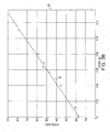
- the vehicle's longitudinal acceleration a Long is measured using an accelerometer and the vehicle's drive force F Drive is determined from the vehicle's axle torque and speed (using equation 7) (step 410). These measurements are made for a given time and the resulting drive force F Drive is plotted against the corresponding longitudinal acceleration a Long (step 420) (see also graph 20 of FIG. 3B ). These measurements are repeated many times. For each measurement, the resulting data point is added to the graph 20.
- the vehicle mass m is equal to the slope of a line connecting data points of drive force F Drive plotted against longitudinal acceleration a Long .
- the distribution of the data points may be approximated as a line or any other desired function (step 430).
- a line 22 is determined using a least squares method. The line 22 is fit to the data points plotted in graph 20, and the slope of the interpolated line 22 is the determined mass m of the vehicle 10 (step 440). Data points continue to be added to the graph 20, and the slope of the fitted line 22 is adjusted until a reset signal is received (as further explained below), wherein the process begins anew (steps 450, 460). If desired, the least squares method can proceed by adding new data points while disposing of sufficiently old data points to keep the slope of the determined line 22 based primarily upon recent data points.
- the slope m and y-intercept b values are given generically in equations 8 and 9, where x and y values may be substituted by data points for longitudinal acceleration a Long and drive force F Drive , respectively, in the current application.
- Equation 11 is illustrated in FIG. 4 , which shows a value for drive force F Drive in terms of vehicle speed V Spd and longitudinal acceleration a Long .
- the mass m and coefficients A, B, C of equation 11 may be simultaneously solved using a regression function. Therefore, using the regression function, the data is fit to a surface whose slope in the drive force F Drive /longitudinal acceleration a Long plane is the value of the vehicle's mass m. This is illustrated in FIGS. 5A and 5B .
- a least squares method may be efficiently used to solve for the coefficients A, B, C and the mass m.
- F Drag A + B ⁇ V Spd + C ⁇ V Spd 2
- the vehicle's longitudinal acceleration a Long is measured using an accelerometer and the vehicle's drive force F Drive is determined from the vehicle's axle torque and speed (using equation 7) (step 210), just as in step 410 of method 400. Additionally, the vehicle's speed V Spd is determined as well. Using these data sources and the least squares recursive method, equation 11 is solved and the drive force F Drive is plotted as a function of vehicle speed V Spd and longitudinal acceleration a Long (step 220) (see also graph 24 of FIG. 5B ). These measurements are repeated many times. For each measurement, the resulting data point is added to the graph 25. The distribution of the data points may be approximated as a surface representing drive force F Drive (step 230).
- the vehicle mass m is equal to the slope of the drive force F Drive surface in the drive force F Drive /longitudinal acceleration a Long plane.
- a surface 27 is determined using the least squares method. The surface 27 is fit to the data points plotted in graph 25. Solid data points are located above the best fit surface, while hollow data point are located below the determined surface. The slope of the interpolated surface 27 in the drive force F Drive /longitudinal acceleration a Long plane is the determined mass m of the vehicle 10 (step 240). Data points continue to be added to the graph 25, and the surface 27 is adjusted until a reset signal is received (as further explained below), wherein the process begins anew (steps 250, 260). If desired, the least squares method can proceed by adding new data points while disposing of sufficiently old data points to keep the surface 27 based primarily upon recent data points.
- vehicle mass m determined using any of the methods presented above may be sufficient for most purposes, the mass determination may be further refined by accounting for many other variables that may affect the accelerometer measurements. Refinements can be made, for example, to correct for the effects of pitch and lateral acceleration. Vehicle pitch may be caused by acceleration, air drag and load, while lateral acceleration may be caused by cornering, as explained below.
- a vehicle may pitch in one or more directions. For example, as a vehicle accelerates in a forward-moving direction, the vehicle may pitch backwards. A forward-moving vehicle that suddenly decelerates may pitch forward. This pitching action results in the vehicle's accelerometer being pitched or tilted as well. In the methods presented above, however, the accelerometer output, or the longitudinal acceleration a Long signal, is assumed to be parallel to the driving surface. Therefore, measurements made from the vehicle's accelerometer when the vehicle is pitching as a result of vehicle acceleration may introduce error into the mass determination.
- Vehicle and accelerometer pitch caused by acceleration is compensated by modifying the accelerometer signal according to a pitch stiffness of the vehicle.
- Vehicles have a pitch stiffness that is based on the vehicle's suspension system.
- the vehicle's pitch stiffness describes the amount of pitch the vehicle experiences as a function of acceleration. For example, a given vehicle may experience four degrees of pitch for the first "g" of acceleration (1 g). Additional “g's” may result in additional pitch, though the relationship between the vehicle's pitch and the vehicle's acceleration is rarely linear.
- the vehicle's pitch stiffness can be experimentally determined, with the results being stored for use by the vehicle as a lookup table or other data structure.
- the signal measured from the vehicle's accelerometer is adjusted using the angle of vehicle pitch experimentally known to occur for the measured acceleration. Therefore, the signal value used as longitudinal acceleration a Long is a component of the signal output by a vehicle's accelerometer.
- Lateral loads on the vehicle which are produced during cornering events, affect the longitudinal acceleration and drive force signals.
- the longitudinal acceleration is affected because the centripetal acceleration generated in a corner does not necessarily point at a right angle to the longitudinal accelerometer. This effect must be corrected on the longitudinal acceleration signal. Additionally, the slip angle that produces lateral acceleration increases tire drag. Because of this effect, the lateral acceleration is monitored, and the drive force is corrected accordingly.
- Additional sources of vehicle pitch may also be compensated for in the mass determinations, depending on the severity of the pitch-based effect. For example, if the vehicle's accelerometer is installed in the vehicle so that the accelerometer is tilted relative to the driving surface, the angle of tilt could be factored into the determination of longitudinal acceleration a Long . Additionally, aero drag can result in vehicle pitch. However, because the above-described methods determine mass by comparing two or more different measurements during a vehicle's journey, any offset caused by drag is generally minimal and, if desired, could be ignored. Similarly, although various vehicle loads may affect the vehicle's pitch, the effect of load in the calculation of the vehicle's mass m is generally ignored because pitch changes due to load are relatively constant for a journey. Because equation 6, for example, reflects a difference measurement, the effect of load pitch is either canceled out or is negligible.
- Other conditions that may be accounted for include dynamic events due to bumps in the driving surface, for example.
- the methods recognize transient events and then ignore data generated by these dynamic events.
- the events may be detected by comparing a body acceleration calculated from the transmission output speed with the longitudinal acceleration a Long output from the vehicle's accelerometer. When the rates of these two accelerations are significantly different, then the body is known to be pitching in a transient event. When the change in acceleration is near zero, then an absolute limit between the accelerations is imposed.
- Transient events may also be determined by monitoring drive force F Drive and longitudinal acceleration a Long rates. Experiments have shown that the timing of acceleration and force signals is difficult to match during transient events. Therefore, drive force and acceleration data that is not within a calibratable limit is assumed to represent a transient event and is ignored.
- Input data such as vehicle speed V Spd , longitudinal acceleration a Long and axle torque T Axle can each be refined for use in the above-described methods by collecting and averaging a sufficient number of samples. Sample collection must generally occur within certain constraints. For example, samples collected while the vehicle is braking are not used. In general, the above-described methods are most accurate when vehicle axle speed is above 150 revolutions/minute. In this axle speed range, samples may be collected every 0.02 seconds, for example, with 40 samples being sufficient for calibration and averaging.
- confidence in the accuracy of mass calculations is improved when the number of data points collected is above a minimal threshold and a high percentage of the data points have values within a predetermined spread or percentage range.
- the minimum number of data points, the percentage of data that must be within a predetermined spread, and the predetermined spread values may all be determined experimentally.
- the determined slope of the line will converge to the new mass as new data points are added to the plot, displacing old data points.
- the slope of the best-fitted line should approximate the new mass of the vehicle. While this method results in a stable mass determination that is generally invariant to noise and other artifacts, the adjustment of the mass determination using this method may be slower than desired.
- Another option for adjusting the mass calculation when the vehicle's mass changes is to reset the data points every time the vehicle comes to a stop.
- mass calculations would only require a small number of data points (e.g., 100) for consideration in determining the best fit for a line whose slope indicates the mass of the vehicle.
- This solution has a quick response time to changes in the vehicle's mass, but introduces noise and inaccuracy in the resultant slope.
- a third and desired option combines the long averages of the first option and the reset capabilities of the second option.
- load or unload events may be detected by the vehicle's accelerometer. For example, when 40-pound bags of salt are loaded or unloaded from a pickup truck, the truck bounces, an event that results in accelerometer output spikes. Additionally, when a trailer is hitched to a pickup truck, the additional weight causes the vehicle to pitch.
- the accelerometer output is monitored (step 510) for spikes indicative of load or unload events when a vehicle has come to rest (520). If the monitored accelerometer indicates a significant change (step 530), the memory is reset (step 540).
- the mass calculation/slope determination continues to use the most recent data points.
- the method 500 is able to differentiate between frequent vehicular stops for traffic signals and relatively infrequent load/unload events. Accuracy and stability of the determinations are thus improved while good response times are still available.
- the accuracy of the mass determinations described above may be further refined by incorporating additional methods for mass determinations into the above methods. While specific alternative methods to mass determination may not be independently sufficiently accurate, when used in conjunction with the above described mass determination methods, the alternative methods can improve the accuracy of the determined mass.
- One such alternative method that may be used in combination with the above methods uses brake torque measurements to collect additional data points.
- acceleration and drive force data would not be collected during a braking event. However, braking events may still be useful.
- Most brake systems use a pressure transducer to determine the cylinder pressure applied during a braking event. Some brake systems may even include a pressure sensor at each wheel. Using these sensors and knowledge about the properties of the brake components, a value for axle torque T Axle may be calculated.
- the axle torque T Axle values determined through the brake system may be used to determine drive force F Drive .
- the calculated drive force F Drive values are paired with corresponding longitudinal acceleration a Long values from the vehicle's accelerometer. The combined data points result in a greater number of data points to be used in fitting a line or a surface to the data points.
- braking events typically result in deceleration data that is higher in magnitude than that resulting from acceleration events.
- the resulting spread in the combined data points is greater than that which occurs using only powertrain torque data.
- a larger spread between a high number of data points results in a more accurately fitted line or surface. Therefore, by using brake torque data points in conjunction with powertrain drive torque data points in plotting a best-fit line or surface, fitting accuracy is improved.
- a high confidence level may be obtained by first determining the vehicle's mass using the powertrain drive torque, then determining the vehicle's mass using the vehicle's brake system, and then comparing the results. When the compared results are similar, the results may be combined to yield a more refined value for the vehicle mass. When the results are disparate, only powertrain drive torque results are used.
- Mass that is determined using any of the methods described above may be indicated to the driver of the vehicle.
- One display method illustrated in FIG. 7 includes a bar chart.
- the display 600 shows an outline of a vehicle with a number of cargo-shaped bars in the form of a bar graph.
- the display 600 indicates the amount of cargo being carried by the vehicle using bars.
- the cargo boxes 610 in the bed of the vehicle would fill when the measured cargo weight was equal to the gross vehicle weight rating (GVWR) of the vehicle.
- GVWR gross vehicle weight rating
- GCWR gross combined weight rating
- the display 600 could also alert the driver to which trailer classification is required and when trailer brakes are needed, based on the measured mass.
- the vehicle is carrying cargo that exceeds the vehicle's GVWR but is still less than the vehicle's GCWR.
- the mass determination using any of the above methods can be used in assisting in automatic trailer brake adjustment.
- Many pickup trucks include a trailer brake controller that allows a vehicle driver to manually adjust the amount of braking asserted by the trailer brake of an attached trailer. This adjustment is normally made each time the mass of the trailer is changed (upon load or unload events), or when a new trailer is connected to the vehicle.
- the amount of adjustment or the gain can be learned by the system by monitoring brake torque and vehicle longitudinal acceleration a Long .
- the automatic adjustment system can also accept as input the result of a mass determination performed using any of the above-specified methods, thus indicating to the system when mass has changed and adjustment is needed.
- Mass determinations may additionally be applied to a vehicle's electronic stability control (ESC) system to optimize the stability of the vehicle. Mass determinations can be used to enhance the effectiveness of exhaust braking and transmission shifting grade hunting logic. The mass determinations can enhance drive strategies for improved efficiency. Vehicles with high loads, as determined using the methods above, could even be equipped to communicate with other vehicles so as to alert neighboring vehicles to stay further away from the highly loaded vehicle. These and other applications of knowing a vehicle's mass are available.
- ESC electronic stability control
- the vehicle's accelerometer can also be used to determine the drag force F Drag exerted on the vehicle.
- drag force F Drag includes the forces acting upon the vehicle due to aero, tire and mechanical drag in the driveline.
- the coefficients A, B, C in equation 10 are representative of these different types of drag.
- Tire and mechanical drag in the driveline is modeled using coastdown coefficients A and B.
- the effect of aero drag is modeled using coefficient C. Therefore, using equation 11 and the recursive method presented above for solving the coefficients A, B, C, the drag force F Drag may be calculated. This information is useful, for example, in determining and displaying to the driver of the vehicle the distance that the vehicle can travel until the fuel tank is empty.
- the value of coefficient B may be used to indicate the type of driving surface being driven on by the vehicle.
- the vehicle accelerometer may also be used to determine the incline of the driving surface upon which the vehicle is driving. This determination can be performed using knowledge of the vehicle's longitudinal acceleration a Long and knowledge of the vehicle's body acceleration a Veh .
- Body acceleration a Veh is determined as the time derivative of wheel or transmission output speed.
- Wheel speed is determined by multiplying a wheel's circumference with the number of rotations of the wheel in a given period of time (often denoted as RPM or revolutions per minute). A wheel's circumference is given by ⁇ *d Tire , where d Tire is the diameter of the wheel.
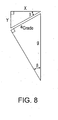
- incline or percent grade is given by y/x.
- angle ⁇ is equal to the arcsin of (a Grade / g).
- percent grade y/x is given by equation 13.
- equation 13 may be rewritten as equation 14.
- grade acceleration a Grade is equal to the difference between longitudinal acceleration a Long and vehicular acceleration a Veh
- equation 14 may be expanded (as in equation 15) and then simplified (as in equation 16) to result in a solution for percent grade y/x in terms of longitudinal acceleration a Long and vehicular acceleration a Veh .
- vehicular acceleration a Veh is measured by determining the derivative of a speed sensor in the vehicle's drivetrain, for example, the vehicle output speed or wheel speed sensors.
- the signals output from the measured speed sensors can be unreliable. Specifically, questions arise regarding the reliability of these speed sensors during vehicle operation at low speed or when the vehicle is slipping on the vehicle's driving surface. Therefore, to improve the accuracy of the vehicular acceleration a Veh determinations, the time derivative of the vehicle's speed is determined using one of at least two methods.
- speed sensor output data is sampled several times and the samples are averaged together to create an averaged sample.
- the derivative of the averaged speed samples is then determined by finding a difference between averaged samples.
- a plurality of speed sensor data points are plotted with respect to time. Then, using a least squares method, a line is fit to the plotted data points. The determined slope of the line is the desired vehicular acceleration a Veh .
- a model relating wheel speed to tire slip may also be implemented. Even on dry concrete, tires may slip as much as 20% during traction-limited acceleration. For lower friction coefficient surfaces, such as wet roads, the slip for a given acceleration also varies. Tire slip may be modeled as a linear function up to a peak friction coefficient where the tire breaks away. Using this linear relationship, measured wheel speed using a speed sensor may be compensated for tire slip as a function of the longitudinal acceleration a Long . Tire slip, however, only creates an issue if vehicular acceleration is determined using speed sensors at driven wheels. If non-driven wheels are used to determine vehicular acceleration a Veh , tire slip need not be compensated for. More complex models defining tire slip may also account for tire inflation pressure, tread depth, loads and temperature, among other factors.
- Slope determination is an input in vehicle grade hunting systems and in dual-powered or hybrid-powered vehicles that many require a specific power source (e.g., gasoline or electric) when climbing slopes of a minimum grade.
- a specific power source e.g., gasoline or electric
- the vehicle's mass may be determined.
- an applied drag force and a driving surface incline may be determined.
- only existing vehicle sensors are necessary to make the desired determinations.
- the determined results may be used in existing and new vehicle systems.
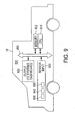
- FIG. 9 reflects one such embodiment, illustrating a processor system 800 in a vehicle 10.
- the processor system 800 includes a memory device 802.
- a processor system such as a computer system, generally comprises a central processing unit (CPU) 810, such as a microprocessor, a digital signal processor, or other programmable digital logic devices, which communicates with a sensor input 820 and an output device 825 over at least one bus 890.
- the memory device 802 communicates with the CPU 810 over bus 890 typically through a memory controller.
- the memory device 802 is used for storing samples obtained through the sensor input 820.
- the sensor input 820 is coupled to various sensors in the vehicle 10, including an accelerometer 830, speed sensor 840, and pressure sensor 850, among others.
- the CPU 810 processes data received through the sensor input 820 and outputs results such as the vehicle mass, drag force or driving surface incline through the output 825. Output results are either reused by various systems in vehicle 10 or are displayed to the users of the vehicle 10.
- multiple CPUs 810 may be used in system 800, and the entire system 800 could be implemented as a system on a chip (SOC), through integrated circuits (ICs), or through other methods known in the art.
Landscapes
- Engineering & Computer Science (AREA)
- Mechanical Engineering (AREA)
- General Engineering & Computer Science (AREA)
- Transportation (AREA)
- Physics & Mathematics (AREA)
- General Physics & Mathematics (AREA)
- Automation & Control Theory (AREA)
- Mathematical Physics (AREA)
- Control Of Driving Devices And Active Controlling Of Vehicle (AREA)
- Electric Propulsion And Braking For Vehicles (AREA)
Description
- The technology herein relates generally to using existing vehicular sensors to determine non-sensed vehicular characteristics. More particularly, the technology herein relates to using a vehicle's accelerometer to determine the vehicle's mass, drag coefficient and a driving surface incline.
- Modern vehicles such as automobiles include multiple control systems that regulate the operation of various components of the vehicle. In many cases, the control systems use input data from one or more sensors. The sensors provide data that is used to optimize the vehicle's operation. As the number of control systems increases and as the control systems themselves become more complex, additional sensors are often used to provide additional data to the control systems. However, the inclusion of additional sensors to the vehicle adds to the vehicle's complexity and cost.
- One vehicle system that uses sensors for data input is the vehicle's powertrain and associated control system. The powertrain in a motor vehicle refers to the group of components that generate and deliver power to a road surface. The powertrain generally includes the motor vehicle's engine and transmission. Other vehicle components such as the vehicle's driveshafts, differentials and drive wheels may also be grouped as part of the powertrain. The powertrain is controlled using a control system. The control system ensures that the powertrain generates a desired power (for example, to propel a vehicle forward along a level surface). Optimal control of the powertrain, however, requires knowledge of the vehicle's mass, among other factors. For instance, knowledge of the vehicle's mass is necessary to determine how to modify a "driving strategy." Driving strategy dictates shift pattern (or when to shift gears of the vehicle) and is compensated by knowledge of the vehicle's mass.
- Because a vehicle's mass can dramatically change during operation of the vehicle, optimum operation of the vehicle's powertrain requires that the vehicle's mass be frequently determined. For example, in a commercial vehicle, a fully loaded vehicle could have a mass that is as much as three times the mass of the unloaded vehicle. Non-commercial vehicles also change mass as a result of loading and unloading, hitching trailers and other accessories that add to or otherwise change the total mass being driven by the vehicle's powertrain.
- In order to dynamically measure a vehicle's mass and provide input to the vehicle's powertrain, some commercial vehicles include one or more mass detection sensors. These sensors are designed specifically to determine the vehicle's mass, and, as an extra component, add to the overall cost and complexity of the vehicle. Perhaps because of this additional cost, non-commercial vehicles generally do not utilize the additional mass detection sensors. Instead, an approximated mass value for the vehicle is used as a constant, non-changing input to powertrain calculations. While this reduces initial cost and complexity, the use of the constant mass value regardless of changes in the vehicle's mass results in sub-optimal control of the vehicle's powertrain.
- There exists, then, a need and a desire for a system capable of dynamically calculating a vehicle's mass and other characteristics without using additional mass detection sensors.
-
DE 102 45 270 A1 , considered as the closest prior art, discloses a system for calculating a vehicle's mass based on engine power, acceleration, velocity, and road inclination. This document teaches using instantaneous values as opposed to values collected at different times. In particular, the document does not disclose using differences between accelerometer signals and differences in vehicle drive force values (which correspond in time with the accelerometer signals) to determine the vehicle mass. - In various example embodiments, the technology described herein provides a method and system for determining vehicle driving characteristics such as the vehicle mass, drag force coefficients and driving surface inclination. The vehicle's mass, drag force coefficients and inclination are determined using signals input from the vehicle's accelerometer. The determination is accomplished without requiring a signal from a specialized mass, drag force or inclination sensor.
- There has thus been outlined, rather broadly, the features of the technology in order that the detailed description that follows may be better understood, and in order that the present contribution to the art may be better appreciated. There are additional features of the technology that will be described and which will form the subject matter of the claims. Additional aspects and advantages of the technology will be apparent from the following detailed description of an exemplary embodiment which is illustrated in the accompanying drawings. The technology is capable of other embodiments and of being practiced and earned out in various ways. Also, it is to be understood that the phraseology and terminology employed are for the purpose of description and should not be regarded as limiting.
- The technology is illustrated and described herein with reference to the various drawings, in which like reference numbers denote like method steps and/or system components, and in which:
-
FIG. 1 is an illustration of forces exerted by or on a motor vehicle, according to a disclosed embodiment; -
FIG. 2 illustrates a method of determining a vehicle's mass, according to a disclosed embodiment; -
FIG. 3A illustrates a method of determining a vehicle's mass, according to a disclosed embodiment; -
FIG. 3B is a graph illustrating a method of determining a vehicle's mass, according to a disclosed embodiment; -
FIG. 4 is a graph illustrating a value of drive force FDrive in terms of vehicle speed VSpd and longitudinal acceleration aLong, according to a disclosed embodiment; -
FIG. 5A illustrates a method of determining a vehicle's mass, according to a disclosed embodiment; -
FIG. 5B is a graph illustrating a method of determining a vehicle's mass, according to a disclosed embodiment; -
FIG. 6 illustrates a method of determining when to reset a vehicle mass calculation, according to a disclosed embodiment; -
FIG. 7 illustrates a method of displaying a vehicle's relative mass, according to a disclosed embodiment; -
FIG. 8 illustrates a method of determining a driving surface incline based on acceleration measurements, according to a disclosed embodiment; and -
FIG. 9 is a vehicle processing system, according to a disclosed embodiment. - Before describing the disclosed embodiments of the technology in detail, it is to be understood that the technology is not limited in its application to the details of the particular arrangement shown here since the technology is capable of other embodiments. Also, the terminology used herein is for the purpose of description and not of limitation.
- In various example embodiments, the technology described herein provides methods of determining a vehicle's mass by using data output by the vehicle's accelerometer. The vehicle's drag coefficient and the incline of the vehicle's driving surface may also be determined using the vehicle's accelerometer. Applications of said determinations are also provided herein as various example embodiments. Other applications and comparable uses are also contemplated herein, as will be obvious to those of ordinary skill in the art.
- The mass of a vehicle may be dynamically determined without the use of specific mass detection sensors. Instead, mass determination is facilitated using other sensors and torque models already calculated and utilized by the vehicle control system. For example, a vehicle's mass may be determined using knowledge of the vehicle's longitudinal acceleration, speed and powertrain output torque, as explained below.
-
FIG. 1 illustrates the typical longitudinal forces exerted on amotor vehicle 10. These forces include the longitudinal forces due to the vehicle's mass, summarized as the vehicle's mass force FMass. The mass force FMass includes forces that arise from changes in vehicle speed and from the grade of the driving surface. The drive force FDrive is the force resulting from the powertrain operation that propels thevehicle 10 forward. The drive force FDrive is opposed by a drag force FDrag. The drag force FDrag is the force acting upon thevehicle 10 by friction with external surfaces or volumes. For example, the drag force FDrag includes aero-induced drag as well as tire-based frictional forces that may be described as a function of vehicle speed. Thevehicle 10 includes at least one accelerometer that measures the vehicle's longitudinal acceleration aLong. - The relationship between the identified longitudinal forces may be summarized as shown below in
equation 1.
- Mass force FMass may also be written in terms of longitudinal acceleration aLong, as illustrated below in equation 2.

- The longitudinal acceleration aLong used in equation 2 and associated with the mass force FMass may be directly read from the vehicle's accelerometer. Therefore,
equation 1 may be rewritten as equation 3, where longitudinal acceleration aLong is a known value.
- From equation 3, the vehicle's mass may be determined with knowledge of the vehicle's drive force FDrive, the drag force FDrag, and the longitudinal acceleration aLong. The vehicle's longitudinal acceleration aLong is known from the vehicle's accelerometer. The vehicle's drive force FDrive can be derived from the vehicle powertrain's output torque, as explained below. Additionally, it is reasonable to assume that, for a short period of time on any given journey by the vehicle, external conditions that affect the drag force FDrag are generally constant. Therefore, the drag force FDrag for
vehicle 10 will be constant for any given vehicle velocity during the short period of time on any given journey. In other words, regardless of whether thevehicle 10 is traveling 20 miles/hour on flat terrain or 20 miles/hour on an incline, as long as thevehicle 10 is subject to the same external factors such as air and tire friction, the drag force FDrag applied to thevehicle 10 is the same in both situations. Mathematically, this is shown in equation 4. Equation 4 is derived from solving equation 3 for the drag force FDrag, applying the solution to two different scenarios (scenario 1 and scenario 2, each with a corresponding drive force FDrive1, FDrive2, a corresponding mass force FMass1, FMass2, and a corresponding drag force FDrag1, FDrag2), and then assuming that the two drag forces FDrag1, FDrag2 are the same for a given speed and time period. Therefore, equation 4 is true for a given vehicle considered atscenario 1 and scenario 2, where the vehicle's velocity and external friction-induced drag forces are constant in both scenarios.
- Equation 2 can be applied to equation 4. Appropriate rearrangement of equation 4 yields equation 5. Equation 5 can be solved for the vehicle's mass m, as indicated in equation 6. Therefore, the mass m of
vehicle 10 may be calculated if the vehicle's accelerometer output is known at two different times when the vehicle is traveling at the same velocity, and if the vehicle's drive force FDrive is also known for the given times.

- As mentioned above, the drive force FDrive for
vehicle 10 may be derived from the output torque of the vehicle's axle. The drive force FDrive is the force that the vehicle's tire exerts on the driving surface, therefore any relationship between the output torque of the vehicle's axle and the drive force FDrive must consider any vehicle components through which the drive force FDrive is applied between the vehicle's axle and the road. These components include wheel bearings, brakes and tires. In general, then, the drive force FDrive forvehicle 10 is related to the force resulting from the vehicle's axle torque less any drag force caused by the intermediary components. The force resulting from the vehicle's axle torque is equal to the axle torque TAxle divided by the vehicle's tire radius rTire (or the distance between the vehicle's axle and the driving surface), as illustrated in equation 7. While drive force may be modeled using more complex models that include components of driveline torque that are functions of vehicle speed, these components may be neglected, since they do not affect the value of the δFDrive/δaLong ratio of equation 6.
- Determination of a vehicle's mass using equations 6 and 7 is performed using various methods, as explained below. In a
first method 300, illustrated inFIG. 2 , vehicle accelerometers are used to make measurements at a variety of different speeds (step 310). Each accelerometer measurement is stored in memory with associated axle torque data (step 320). When thevehicle 10 returns to a speed for which measurements had previously been taken (step 330), additional measurements are made (step 340), equations 6 and 7 are invoked, and a mass for thevehicle 10 is determined (step 360). If desired, the mass determination step can be made optional, only occurring if the difference between the current measurements and the stored measurements is greater than a predefined threshold (optional step 350). This process is repeated for each of many different speeds at which measurements are taken. The final results from each speed are averaged together to yield a determined mass for the vehicle (step 370). - In a second method, illustrated in
FIGS. 3A and3B , a least squares method is applied to determine the vehicle's mass. In theleast squares method 400, the vehicle's longitudinal acceleration aLong is measured using an accelerometer and the vehicle's drive force FDrive is determined from the vehicle's axle torque and speed (using equation 7) (step 410). These measurements are made for a given time and the resulting drive force FDrive is plotted against the corresponding longitudinal acceleration aLong (step 420) (see also graph 20 ofFIG. 3B ). These measurements are repeated many times. For each measurement, the resulting data point is added to thegraph 20. As equation 6 demonstrates, the vehicle mass m is equal to the slope of a line connecting data points of drive force FDrive plotted against longitudinal acceleration aLong. The distribution of the data points may be approximated as a line or any other desired function (step 430). In the example ofFIG. 3B , aline 22 is determined using a least squares method. Theline 22 is fit to the data points plotted ingraph 20, and the slope of the interpolatedline 22 is the determined mass m of the vehicle 10 (step 440). Data points continue to be added to thegraph 20, and the slope of the fittedline 22 is adjusted until a reset signal is received (as further explained below), wherein the process begins anew (steps 450, 460). If desired, the least squares method can proceed by adding new data points while disposing of sufficiently old data points to keep the slope of thedetermined line 22 based primarily upon recent data points. - Under the least squares method, the determined line is modeled as a first-degree polynomial function in the standard form of y = m*x+b, where y and x represent data points along the y-axis and x-axis, respectively, m represents the slope of the polynomial function (remember, the slope is also representative of mass m), and b is the y-intercept. The slope m and y-intercept b values are given generically in
equations 

- In a third method, the principles of equations 6 and 7 and
FIG. 3B are extrapolated from a two-dimensional slope determination and applied to a three-dimensional surface determination. Recall from equation 3 that drive force FDrive is equal to the sum of the drag force FDrag and mass force FMass, which is also mass m multiplied by longitudinal acceleration aLong. The drag force FDrag may be modeled according toequation 10, where VSpd is the vehicle speed and A, B and C are coastdown coefficients. Thus, equation 3 may be rewritten as equation 11. Equation 11 is illustrated inFIG. 4 , which shows a value for drive force FDrive in terms of vehicle speed VSpd and longitudinal acceleration aLong. If the value of the drive force FDrive is known using equation 7, and the values of longitudinal acceleration aLong and vehicle speed VSpd are known from the appropriate sensors, the mass m and coefficients A, B, C of equation 11 may be simultaneously solved using a regression function. Therefore, using the regression function, the data is fit to a surface whose slope in the drive force FDrive/longitudinal acceleration aLong plane is the value of the vehicle's mass m. This is illustrated inFIGS. 5A and5B . A least squares method may be efficiently used to solve for the coefficients A, B, C and the mass m.

- In the
third method 200, the vehicle's longitudinal acceleration aLong is measured using an accelerometer and the vehicle's drive force FDrive is determined from the vehicle's axle torque and speed (using equation 7) (step 210), just as instep 410 ofmethod 400. Additionally, the vehicle's speed VSpd is determined as well. Using these data sources and the least squares recursive method, equation 11 is solved and the drive force FDrive is plotted as a function of vehicle speed VSpd and longitudinal acceleration aLong (step 220) (see also graph 24 ofFIG. 5B ). These measurements are repeated many times. For each measurement, the resulting data point is added to thegraph 25. The distribution of the data points may be approximated as a surface representing drive force FDrive (step 230). As equation 6 demonstrates, the vehicle mass m is equal to the slope of the drive force FDrive surface in the drive force FDrive/longitudinal acceleration aLong plane. In the example ofFIG. 5B , asurface 27 is determined using the least squares method. Thesurface 27 is fit to the data points plotted ingraph 25. Solid data points are located above the best fit surface, while hollow data point are located below the determined surface. The slope of the interpolatedsurface 27 in the drive force FDrive/longitudinal acceleration aLong plane is the determined mass m of the vehicle 10 (step 240). Data points continue to be added to thegraph 25, and thesurface 27 is adjusted until a reset signal is received (as further explained below), wherein the process begins anew (steps 250, 260). If desired, the least squares method can proceed by adding new data points while disposing of sufficiently old data points to keep thesurface 27 based primarily upon recent data points. - While vehicle mass m determined using any of the methods presented above may be sufficient for most purposes, the mass determination may be further refined by accounting for many other variables that may affect the accelerometer measurements. Refinements can be made, for example, to correct for the effects of pitch and lateral acceleration. Vehicle pitch may be caused by acceleration, air drag and load, while lateral acceleration may be caused by cornering, as explained below.
- During acceleration, a vehicle may pitch in one or more directions. For example, as a vehicle accelerates in a forward-moving direction, the vehicle may pitch backwards. A forward-moving vehicle that suddenly decelerates may pitch forward. This pitching action results in the vehicle's accelerometer being pitched or tilted as well. In the methods presented above, however, the accelerometer output, or the longitudinal acceleration aLong signal, is assumed to be parallel to the driving surface. Therefore, measurements made from the vehicle's accelerometer when the vehicle is pitching as a result of vehicle acceleration may introduce error into the mass determination.
- Vehicle and accelerometer pitch caused by acceleration is compensated by modifying the accelerometer signal according to a pitch stiffness of the vehicle. Vehicles have a pitch stiffness that is based on the vehicle's suspension system. The vehicle's pitch stiffness describes the amount of pitch the vehicle experiences as a function of acceleration. For example, a given vehicle may experience four degrees of pitch for the first "g" of acceleration (1 g). Additional "g's" may result in additional pitch, though the relationship between the vehicle's pitch and the vehicle's acceleration is rarely linear. The vehicle's pitch stiffness can be experimentally determined, with the results being stored for use by the vehicle as a lookup table or other data structure. Thus, to correct a vehicle's mass calculation for the vehicle's acceleration-based pitch, the signal measured from the vehicle's accelerometer is adjusted using the angle of vehicle pitch experimentally known to occur for the measured acceleration. Therefore, the signal value used as longitudinal acceleration aLong is a component of the signal output by a vehicle's accelerometer.
- Lateral loads on the vehicle, which are produced during cornering events, affect the longitudinal acceleration and drive force signals. The longitudinal acceleration is affected because the centripetal acceleration generated in a corner does not necessarily point at a right angle to the longitudinal accelerometer. This effect must be corrected on the longitudinal acceleration signal. Additionally, the slip angle that produces lateral acceleration increases tire drag. Because of this effect, the lateral acceleration is monitored, and the drive force is corrected accordingly.
- Additional sources of vehicle pitch may also be compensated for in the mass determinations, depending on the severity of the pitch-based effect. For example, if the vehicle's accelerometer is installed in the vehicle so that the accelerometer is tilted relative to the driving surface, the angle of tilt could be factored into the determination of longitudinal acceleration aLong. Additionally, aero drag can result in vehicle pitch. However, because the above-described methods determine mass by comparing two or more different measurements during a vehicle's journey, any offset caused by drag is generally minimal and, if desired, could be ignored. Similarly, although various vehicle loads may affect the vehicle's pitch, the effect of load in the calculation of the vehicle's mass m is generally ignored because pitch changes due to load are relatively constant for a journey. Because equation 6, for example, reflects a difference measurement, the effect of load pitch is either canceled out or is negligible.
- Other conditions that may be accounted for include dynamic events due to bumps in the driving surface, for example. Instead of modeling body damping and other vehicle movements resulting from the driving surface conditions, the methods recognize transient events and then ignore data generated by these dynamic events. The events may be detected by comparing a body acceleration calculated from the transmission output speed with the longitudinal acceleration aLong output from the vehicle's accelerometer. When the rates of these two accelerations are significantly different, then the body is known to be pitching in a transient event. When the change in acceleration is near zero, then an absolute limit between the accelerations is imposed.
- Transient events may also be determined by monitoring drive force FDrive and longitudinal acceleration aLong rates. Experiments have shown that the timing of acceleration and force signals is difficult to match during transient events. Therefore, drive force and acceleration data that is not within a calibratable limit is assumed to represent a transient event and is ignored.
- Other conditions that may need to be accounted for include the effect of cold temperatures. Driveline drag increases significantly when fluids are cold. While this effect is modeled in much of the powertrain, the models are inadequate when temperatures become extreme. Therefore, if vehicle temperatures are less than a predetermined threshold, data collected at the extreme temperatures is not used.
- Many other conditions may affect the mass determination, including shift position and a shift-in-progress event. If necessary, data collected at these times can be ignored.
- Input data such as vehicle speed VSpd, longitudinal acceleration aLong and axle torque TAxle can each be refined for use in the above-described methods by collecting and averaging a sufficient number of samples. Sample collection must generally occur within certain constraints. For example, samples collected while the vehicle is braking are not used. In general, the above-described methods are most accurate when vehicle axle speed is above 150 revolutions/minute. In this axle speed range, samples may be collected every 0.02 seconds, for example, with 40 samples being sufficient for calibration and averaging.
- Additionally, confidence in the accuracy of mass calculations is improved when the number of data points collected is above a minimal threshold and a high percentage of the data points have values within a predetermined spread or percentage range. The minimum number of data points, the percentage of data that must be within a predetermined spread, and the predetermined spread values may all be determined experimentally.
- Because a vehicle's mass may change dramatically over time (due to, for example, the loading or unloading of the vehicle or the attaching of trailers to a vehicle), accurate mass determinations using either of the methods presented in
FIGS. 3A-3B or4 must be able to account for changes in mass that occur during the vehicle's journey. One method of accounting for changes in mass, as applied using the least squares method ofFIG. 3A , is to only consider the most recent data points in determining the line or surface fitted to the data points. As an example, in the least squares method, the slope of a line fitted to the data points could be determined with relation to the most recent 1500 data points. Thus, if the mass of the vehicle changes, the determined slope of the line will converge to the new mass as new data points are added to the plot, displacing old data points. Once 1500 data points have been plotted after the change in mass, the slope of the best-fitted line should approximate the new mass of the vehicle. While this method results in a stable mass determination that is generally invariant to noise and other artifacts, the adjustment of the mass determination using this method may be slower than desired. - Another option for adjusting the mass calculation when the vehicle's mass changes is to reset the data points every time the vehicle comes to a stop. In this scenario, mass calculations would only require a small number of data points (e.g., 100) for consideration in determining the best fit for a line whose slope indicates the mass of the vehicle. This solution has a quick response time to changes in the vehicle's mass, but introduces noise and inaccuracy in the resultant slope.
- A third and desired option combines the long averages of the first option and the reset capabilities of the second option. Experimental observation shows that load or unload events may be detected by the vehicle's accelerometer. For example, when 40-pound bags of salt are loaded or unloaded from a pickup truck, the truck bounces, an event that results in accelerometer output spikes. Additionally, when a trailer is hitched to a pickup truck, the additional weight causes the vehicle to pitch. Thus, in the third option, as illustrated in
method 500 ofFIG. 6 , the accelerometer output is monitored (step 510) for spikes indicative of load or unload events when a vehicle has come to rest (520). If the monitored accelerometer indicates a significant change (step 530), the memory is reset (step 540). If not, the mass calculation/slope determination continues to use the most recent data points. In this way, themethod 500 is able to differentiate between frequent vehicular stops for traffic signals and relatively infrequent load/unload events. Accuracy and stability of the determinations are thus improved while good response times are still available. - The accuracy of the mass determinations described above may be further refined by incorporating additional methods for mass determinations into the above methods. While specific alternative methods to mass determination may not be independently sufficiently accurate, when used in conjunction with the above described mass determination methods, the alternative methods can improve the accuracy of the determined mass. One such alternative method that may be used in combination with the above methods uses brake torque measurements to collect additional data points.
- Typically, in the above-described methods, acceleration and drive force data would not be collected during a braking event. However, braking events may still be useful. Most brake systems use a pressure transducer to determine the cylinder pressure applied during a braking event. Some brake systems may even include a pressure sensor at each wheel. Using these sensors and knowledge about the properties of the brake components, a value for axle torque TAxle may be calculated. The axle torque TAxle values determined through the brake system may be used to determine drive force FDrive. The calculated drive force FDrive values are paired with corresponding longitudinal acceleration aLong values from the vehicle's accelerometer. The combined data points result in a greater number of data points to be used in fitting a line or a surface to the data points. As an additional benefit, braking events typically result in deceleration data that is higher in magnitude than that resulting from acceleration events. The resulting spread in the combined data points is greater than that which occurs using only powertrain torque data. A larger spread between a high number of data points results in a more accurately fitted line or surface. Therefore, by using brake torque data points in conjunction with powertrain drive torque data points in plotting a best-fit line or surface, fitting accuracy is improved.
- Because determination of a vehicle's drive force FDrive using the vehicle's brake system is subject to certain errors, this method should only be applied when there is a high degree of confidence in the resulting data. Some of the errors that may occur from the braking system method of determining drive force FDrive include errors due to variations in the friction coefficients of the braking system components. These friction coefficients have been found to vary over a wide range of values. Therefore, determining accurate values for wheel torque using a vehicle's braking system may require development of a friction coefficient model that compensates for speed, temperature and brake pressure. Additionally, the unaccounted use of trailer brakes can significantly skew the values of wheel torque obtained using a vehicle's brake system. If a trailer being towed has its own brakes, the braking information of the trailer is not generally known by the vehicle, and thus the calculated values of wheel torque using the vehicle's brake system will not be complete or accurate.
- Therefore, the data points arising from the vehicle's brake system are only included in the mass determination when confidence in the accuracy of the combined data points is high. A high confidence level may be obtained by first determining the vehicle's mass using the powertrain drive torque, then determining the vehicle's mass using the vehicle's brake system, and then comparing the results. When the compared results are similar, the results may be combined to yield a more refined value for the vehicle mass. When the results are disparate, only powertrain drive torque results are used.
- Mass that is determined using any of the methods described above may be indicated to the driver of the vehicle. One display method illustrated in
FIG. 7 includes a bar chart. InFIG. 7 , thedisplay 600 shows an outline of a vehicle with a number of cargo-shaped bars in the form of a bar graph. When the system detects a significant change in the vehicle's weight, thedisplay 600 indicates the amount of cargo being carried by the vehicle using bars. For example, thecargo boxes 610 in the bed of the vehicle would fill when the measured cargo weight was equal to the gross vehicle weight rating (GVWR) of the vehicle. As additional mass is added, theboxes 620 in the trailer would continue to fill until the mass reached the gross combined weight rating (GCWR) of the vehicle. Thedisplay 600 could also alert the driver to which trailer classification is required and when trailer brakes are needed, based on the measured mass. In the example ofFIG. 7 , the vehicle is carrying cargo that exceeds the vehicle's GVWR but is still less than the vehicle's GCWR. - The mass determination using any of the above methods can be used in assisting in automatic trailer brake adjustment. Many pickup trucks include a trailer brake controller that allows a vehicle driver to manually adjust the amount of braking asserted by the trailer brake of an attached trailer. This adjustment is normally made each time the mass of the trailer is changed (upon load or unload events), or when a new trailer is connected to the vehicle. In an automatic trailer brake adjustment system, the amount of adjustment or the gain can be learned by the system by monitoring brake torque and vehicle longitudinal acceleration aLong. The automatic adjustment system can also accept as input the result of a mass determination performed using any of the above-specified methods, thus indicating to the system when mass has changed and adjustment is needed.
- Mass determinations may additionally be applied to a vehicle's electronic stability control (ESC) system to optimize the stability of the vehicle. Mass determinations can be used to enhance the effectiveness of exhaust braking and transmission shifting grade hunting logic. The mass determinations can enhance drive strategies for improved efficiency. Vehicles with high loads, as determined using the methods above, could even be equipped to communicate with other vehicles so as to alert neighboring vehicles to stay further away from the highly loaded vehicle. These and other applications of knowing a vehicle's mass are available.
- In addition to using a vehicle's accelerometer to calculate the mass m of the vehicle, the vehicle's accelerometer can also be used to determine the drag force FDrag exerted on the vehicle. Recall that drag force FDrag includes the forces acting upon the vehicle due to aero, tire and mechanical drag in the driveline. The coefficients A, B, C in
equation 10 are representative of these different types of drag. Tire and mechanical drag in the driveline is modeled using coastdown coefficients A and B. The effect of aero drag is modeled using coefficient C. Therefore, using equation 11 and the recursive method presented above for solving the coefficients A, B, C, the drag force FDrag may be calculated. This information is useful, for example, in determining and displaying to the driver of the vehicle the distance that the vehicle can travel until the fuel tank is empty. In addition, the value of coefficient B may be used to indicate the type of driving surface being driven on by the vehicle. - The vehicle accelerometer may also be used to determine the incline of the driving surface upon which the vehicle is driving. This determination can be performed using knowledge of the vehicle's longitudinal acceleration aLong and knowledge of the vehicle's body acceleration aVeh. Body acceleration aVeh is determined as the time derivative of wheel or transmission output speed. Wheel speed is determined by multiplying a wheel's circumference with the number of rotations of the wheel in a given period of time (often denoted as RPM or revolutions per minute). A wheel's circumference is given by π*dTire, where dTire is the diameter of the wheel. As vehicle sensors are able to measure the period of rotation of a wheel in minutes, the RPM is equivalent to 1/RFinalDrive, where RFinalDrive is the period in minutes of wheel rotation. Therefore, converting minutes to seconds, the time derivative of the wheel speed is given by equation 12, where NQut represents the number of samples of the wheel rotation period RFinalDrive.

- Using
FIG. 8 as a guide, incline or percent grade is given by y/x. InFIG. 8 , angle β is equal to the arcsin of (aGrade / g). Thus, the percent grade y/x is given by equation 13. As the value of tan(arcsin(x)) may be rewritten as x/(1-x2)^1/2, equation 13 may be rewritten as equation 14. Recalling that grade acceleration aGrade is equal to the difference between longitudinal acceleration aLong and vehicular acceleration aVeh, equation 14 may be expanded (as in equation 15) and then simplified (as in equation 16) to result in a solution for percent grade y/x in terms of longitudinal acceleration aLong and vehicular acceleration aVeh.


- As described above in relation to equation 12, vehicular acceleration aVeh is measured by determining the derivative of a speed sensor in the vehicle's drivetrain, for example, the vehicle output speed or wheel speed sensors. However, under certain conditions, the signals output from the measured speed sensors can be unreliable. Specifically, questions arise regarding the reliability of these speed sensors during vehicle operation at low speed or when the vehicle is slipping on the vehicle's driving surface. Therefore, to improve the accuracy of the vehicular acceleration aVeh determinations, the time derivative of the vehicle's speed is determined using one of at least two methods. In the first method, speed sensor output data is sampled several times and the samples are averaged together to create an averaged sample. The derivative of the averaged speed samples is then determined by finding a difference between averaged samples. In the second method, a plurality of speed sensor data points are plotted with respect to time. Then, using a least squares method, a line is fit to the plotted data points. The determined slope of the line is the desired vehicular acceleration aVeh.
- To further improve the accuracy of the vehicular acceleration aVeh determinations, a model relating wheel speed to tire slip may also be implemented. Even on dry concrete, tires may slip as much as 20% during traction-limited acceleration. For lower friction coefficient surfaces, such as wet roads, the slip for a given acceleration also varies. Tire slip may be modeled as a linear function up to a peak friction coefficient where the tire breaks away. Using this linear relationship, measured wheel speed using a speed sensor may be compensated for tire slip as a function of the longitudinal acceleration aLong. Tire slip, however, only creates an issue if vehicular acceleration is determined using speed sensors at driven wheels. If non-driven wheels are used to determine vehicular acceleration aVeh, tire slip need not be compensated for. More complex models defining tire slip may also account for tire inflation pressure, tread depth, loads and temperature, among other factors.
- Slope determination is an input in vehicle grade hunting systems and in dual-powered or hybrid-powered vehicles that many require a specific power source (e.g., gasoline or electric) when climbing slopes of a minimum grade.
- Therefore, using a vehicle's accelerometer, the vehicle's mass, an applied drag force and a driving surface incline may be determined. In each case, only existing vehicle sensors are necessary to make the desired determinations. Once known, the determined results may be used in existing and new vehicle systems.
- While some aspects of the above disclosure necessarily relate to hardware in a vehicle, methods of determining and applying the above-identified vehicle specifications may be implemented in either software or hardware.
FIG. 9 reflects one such embodiment, illustrating aprocessor system 800 in avehicle 10. Theprocessor system 800 includes amemory device 802. A processor system, such as a computer system, generally comprises a central processing unit (CPU) 810, such as a microprocessor, a digital signal processor, or other programmable digital logic devices, which communicates with asensor input 820 and anoutput device 825 over at least onebus 890. Thememory device 802 communicates with theCPU 810 overbus 890 typically through a memory controller. Thememory device 802 is used for storing samples obtained through thesensor input 820. Thesensor input 820 is coupled to various sensors in thevehicle 10, including anaccelerometer 830,speed sensor 840, andpressure sensor 850, among others. TheCPU 810 processes data received through thesensor input 820 and outputs results such as the vehicle mass, drag force or driving surface incline through theoutput 825. Output results are either reused by various systems invehicle 10 or are displayed to the users of thevehicle 10. Of course,multiple CPUs 810 may be used insystem 800, and theentire system 800 could be implemented as a system on a chip (SOC), through integrated circuits (ICs), or through other methods known in the art. - Although this technology has been illustrated and described herein with reference to preferred embodiments and specific examples thereof, it will be readily apparent to those of ordinary skill in the art that other embodiments and examples can perform similar functions and/or achieve like results. All such equivalent embodiments and examples are within scope of the technology and are intended to be covered by the following claims.
Claims (16)
- A method of equipping a vehicle to determine and use at least one vehicle driving characteristic, the method comprising:providing one or more accelerometers (830) in the vehicle (10), at least one of the one or more accelerometers (830) configured to output accelerometer signals;providing a memory (802) for storing a plurality of accelerometer signals representing vehicle acceleration at different times;providing a processor (810) coupled to said memory (802) and configured to process the plurality of stored accelerometer signals to determine as an output signal a mass of the vehicle (10) based on a difference between at least a portion of the plurality of stored accelerometer signals and a difference between values for the vehicle's drive force that correspond in time with the portion of the plurality of stored accelerometer signals;configuring the processor (810) to determine the mass of the vehicle (10) during vehicle operation by:plotting the portion of the plurality of stored accelerometer signals against the corresponding values for the vehicle's drive force; anddetermining a line that best fits the plotted signals, the vehicle's mass being a slope of the determined line; andcoupling the processor with a vehicle control system (825) to improve vehicle drivetrain performance based on the output signal.
- The method of claim 1, wherein the line is determined using a least squares method.
- The method of claim 1, wherein the processor (810) is further configured to determine the mass of the vehicle (10) by:plotting the values for the vehicle's drive force against the corresponding portion of the plurality of stored accelerometer signals and against a corresponding plurality of speeds of the vehicle (10); anddetermining a surface that best fits the plotted signals, the vehicle's mass being a slope of the determined surface in the drive force/accelerometer plane of the plot.
- The method of claim 3, wherein the surface is determined using a least squares method.
- The method of claim 3, wherein the portion of the plurality of stored accelerometer signals is a most recently input portion.
- The method of claim 5, further comprising sensing a vehicle mass change event.
- The method of claim 6, further comprising configuring the processor (810) so that if a vehicle mass change event is sensed while the vehicle (10) is not moving, the portion of the plurality of stored accelerometer signals used is reset to only include signals input after the vehicle mass change event.
- The method of claim 1, wherein the memory (802) stores the at least a portion of the plurality of accelerometer signals with a corresponding vehicle speed value, as determined by a speed sensor (840) in the vehicle (10);
the method further comprising:configuring the processor (810) to determine the mass of the vehicle (10) by determining a difference between accelerometer signals with same corresponding speed values. - The method of claim 1, further comprising configuring the processor (810) to modify the plurality of stored accelerometer signals to compensate for vehicle pitch due to acceleration.
- The method of claim 1, further comprising providing one or more brake system pressure sensors (850) in the vehicle (10) whose output signals are used by the processor (810) to derive a plurality of wheel torque values to determine drive force values to supplement the already determined drive force values.
- The method of claim 1, further comprising providing the processor output signal for use in adjusting an amount of braking asserted by a trailer brake of a trailer attached to the vehicle, said adjustment based on the determined mass.
- A system for improving a vehicle's drivetrain performance, the system comprising:one or more accelerometers (830) in the vehicle;a memory (802) for storing a plurality of accelerometer signals representing vehicle acceleration at different times;a drivetrain of the vehicle (10), the drivetrain having a determinable drive force; anda processor (810) configured to receive from said memory (802) said plurality of stored accelerometer signals and to determine a mass of the vehicle (10) based on a difference between at least a portion of the plurality of stored accelerometer signals and a difference between values for the vehicle's drive force that correspond in time with the portion of the plurality of accelerometer signals by:plotting the portion of the plurality of stored accelerometer signals against the corresponding values for the vehicle's drive force; anddetermining a line that best fits the plotted signals, the vehicle's mass being a slope of the determined line.
- The system of claim 12, wherein the at least a portion of the plurality of stored accelerometer signals are stored in said memory (802) with corresponding vehicle speed values as determined by at least one speed sensor (840) in the vehicle (10).
- The system of claim 12, wherein a display (825) is used to indicate to an operator of the vehicle the mass of the vehicle (10) as a function of a total mass for which the vehicle (10) is rated to carry.
- The system of claim 12, wherein the processor (810) is further configured to determine drag force coefficients indicating a drag force acting upon the vehicle (10), the processor (810) being configured to recursively determine the drag force coefficients for values of said plurality of stored accelerometer signals at a known vehicle speed and corresponding to a known vehicle drive force.
- The system of claim 12, wherein the processor (810) is further configured to determine an incline of a driving surface upon which the vehicle (10) operates, the incline determination based on a difference between the at least a portion of the plurality of stored accelerometer signals and vehicular acceleration values arising from the derivative of a wheel speed of the vehicle (10).
Applications Claiming Priority (2)
| Application Number | Priority Date | Filing Date | Title |
|---|---|---|---|
| US12/684,145 US9395233B2 (en) | 2010-01-08 | 2010-01-08 | Mass, drag coefficient and inclination determination using accelerometer sensor |
| PCT/US2011/020308 WO2011085060A1 (en) | 2010-01-08 | 2011-01-06 | Mass, drag coefficient and inclination determination using accelerometer sensor |
Publications (2)
| Publication Number | Publication Date |
|---|---|
| EP2521665A1 EP2521665A1 (en) | 2012-11-14 |
| EP2521665B1 true EP2521665B1 (en) | 2015-09-16 |
Family
ID=43746608
Family Applications (1)
| Application Number | Title | Priority Date | Filing Date |
|---|---|---|---|
| EP11700704.7A Not-in-force EP2521665B1 (en) | 2010-01-08 | 2011-01-06 | Mass, drag coefficient and inclination determination using accelerometer sensor |
Country Status (4)
| Country | Link |
|---|---|
| US (1) | US9395233B2 (en) |
| EP (1) | EP2521665B1 (en) |
| CA (1) | CA2786594C (en) |
| WO (1) | WO2011085060A1 (en) |
Cited By (6)
| Publication number | Priority date | Publication date | Assignee | Title |
|---|---|---|---|---|
| US10670479B2 (en) | 2018-02-27 | 2020-06-02 | Methode Electronics, Inc. | Towing systems and methods using magnetic field sensing |
| US10696109B2 (en) | 2017-03-22 | 2020-06-30 | Methode Electronics Malta Ltd. | Magnetolastic based sensor assembly |
| US11084342B2 (en) | 2018-02-27 | 2021-08-10 | Methode Electronics, Inc. | Towing systems and methods using magnetic field sensing |
| US11135882B2 (en) | 2018-02-27 | 2021-10-05 | Methode Electronics, Inc. | Towing systems and methods using magnetic field sensing |
| US11221262B2 (en) | 2018-02-27 | 2022-01-11 | Methode Electronics, Inc. | Towing systems and methods using magnetic field sensing |
| US11491832B2 (en) | 2018-02-27 | 2022-11-08 | Methode Electronics, Inc. | Towing systems and methods using magnetic field sensing |
Families Citing this family (32)
| Publication number | Priority date | Publication date | Assignee | Title |
|---|---|---|---|---|
| DE102010063436A1 (en) * | 2010-12-17 | 2012-06-21 | Robert Bosch Gmbh | Method and device for determining a range of a vehicle |
| GB201105830D0 (en) * | 2011-04-06 | 2011-05-18 | Lysanda Ltd | Mass estimation model |
| US10166980B2 (en) * | 2013-02-28 | 2019-01-01 | Ford Global Technologies, Llc | Vehicle mass computation |
| GB2516916B (en) * | 2013-08-06 | 2016-09-14 | Lacsop Ltd | Method and apparatus for determining the mass of a body |
| FR3014192B1 (en) * | 2013-12-03 | 2015-12-25 | Renault Sas | METHOD AND DEVICE FOR ESTIMATING THE INTERVAL IN WHICH IS THE TOTAL MASS OF A MOTOR VEHICLE |
| US10126160B2 (en) * | 2013-12-19 | 2018-11-13 | Volvo Truck Corporation | Method and vehicle with arrangement for estimating mass of the vehicle |
| US20160016470A1 (en) * | 2014-03-25 | 2016-01-21 | Agco International Gmbh | Tractor control/display systems |
| WO2015164246A1 (en) | 2014-04-22 | 2015-10-29 | Michael Hall | Determining haul weight |
| GB2526806A (en) * | 2014-06-03 | 2015-12-09 | Here Global Bv | Trail interpolation |
| US20150353063A1 (en) * | 2014-06-09 | 2015-12-10 | Continental Automotive Systems, Inc. | Trailer brake system having trailer gain optimization |
| US20160039480A1 (en) * | 2014-08-05 | 2016-02-11 | Agco International Gmbh | Tractor control system |
| GB2535773B (en) * | 2015-02-27 | 2019-10-30 | Jaguar Land Rover Ltd | Vehicle mass estimation |
| GB2535775B (en) * | 2015-02-27 | 2019-10-30 | Jaguar Land Rover Ltd | Vehicle mass estimation |
| FR3054660A1 (en) * | 2016-07-26 | 2018-02-02 | Peugeot Citroen Automobiles Sa | METHOD FOR ESTIMATING THE MASS OF A MOTOR VEHICLE |
| US10053104B2 (en) * | 2016-10-20 | 2018-08-21 | Michael Hall | Determining gross combined weight |
| US10274360B2 (en) * | 2016-11-01 | 2019-04-30 | Hall Labs Llc | Mobile device vehicle weight determination |
| US10071742B2 (en) * | 2017-01-09 | 2018-09-11 | Newvistas Capital, Llc | Determining weight of electric and hybrid vehicles |
| MY204353A (en) * | 2017-02-14 | 2024-08-24 | Mitsubishi Heavy Ind Mach Systems Ltd | Charging system, charging method, and program |
| JP6863064B2 (en) * | 2017-05-12 | 2021-04-21 | いすゞ自動車株式会社 | Vehicle control unit |
| DE102017220860A1 (en) * | 2017-09-28 | 2019-03-28 | Continental Teves Ag & Co. Ohg | Method for determining the position of the center of gravity of a vehicle |
| US10612961B2 (en) * | 2017-12-20 | 2020-04-07 | Gm Global Technology Operateons Llc | Method for real-time mass estimation of a vehicle system |
| US11014417B2 (en) | 2018-02-27 | 2021-05-25 | Methode Electronics, Inc. | Towing systems and methods using magnetic field sensing |
| JP7077708B2 (en) * | 2018-03-28 | 2022-05-31 | いすゞ自動車株式会社 | Gradient estimation device and vehicle |
| JP7040307B2 (en) * | 2018-06-13 | 2022-03-23 | トヨタ自動車株式会社 | A recording medium that records an operation evaluation device, an operation evaluation method, and an operation evaluation program. |
| JP7040306B2 (en) | 2018-06-13 | 2022-03-23 | トヨタ自動車株式会社 | A recording medium that records an operation evaluation device, an operation evaluation method, and an operation evaluation program. |
| CN111198032A (en) * | 2018-11-19 | 2020-05-26 | 陕西汽车集团有限责任公司 | Real-time estimation method for automobile mass |
| DE102019105927B4 (en) * | 2019-03-08 | 2023-05-11 | Knorr-Bremse Systeme für Nutzfahrzeuge GmbH | System and method for determining a load change in a commercial vehicle |
| FR3097508A1 (en) * | 2019-06-18 | 2020-12-25 | Psa Automobiles Sa | A method of regulating the speed of a motor vehicle implementing an adaptive cruise control function |
| US11377111B1 (en) | 2020-08-26 | 2022-07-05 | Allstate Insurance Company | Systems and methods for detecting vehicle mass changes |
| DE102020216109A1 (en) * | 2020-12-17 | 2022-06-23 | Zf Friedrichshafen Ag | Method and control device for determining the mass of a vehicle |
| US20240246373A1 (en) * | 2021-08-27 | 2024-07-25 | Bridgestone Americas Tire Operations, Llc | System and method for real-time estimation of tire rolling resistance force |
| US12286109B2 (en) | 2022-12-27 | 2025-04-29 | Toyota Motor Engineering & Manufacturing North America, Inc. | Adaptive driveforce for speed limit control |
Family Cites Families (19)
| Publication number | Priority date | Publication date | Assignee | Title |
|---|---|---|---|---|
| JPH0694116A (en) * | 1992-09-08 | 1994-04-05 | Hitachi Ltd | Automatic shift control device |
| US5491630A (en) * | 1994-08-03 | 1996-02-13 | Eaton Corporation | Method/system for resetting the value of a control parameter indicative of gross combined weight of vehicles to a default value thereof |
| US5610372A (en) * | 1996-03-14 | 1997-03-11 | The Airsport Corp. | System for measuring total weight and weight distribution of a vehicle |
| JP3633120B2 (en) * | 1996-07-18 | 2005-03-30 | 日産自動車株式会社 | Vehicle speed and road friction coefficient estimation device |
| DE19728867A1 (en) * | 1997-07-05 | 1999-01-07 | Bosch Gmbh Robert | Method of weighing motor vehicle, especially commercial vehicle |
| US6249735B1 (en) * | 1998-01-28 | 2001-06-19 | Aisin Seiki Kabushiki Kaisha | Vehicle state estimation method and vehicular auxiliary brake control apparatus using the method |
| US6167357A (en) * | 1998-04-23 | 2000-12-26 | Cummins Engine Company, Inc. | Recursive vehicle mass estimation |
| JP2000283831A (en) * | 1999-03-31 | 2000-10-13 | Mitsubishi Motors Corp | Apparatus for determining vehicle weight and road slope |
| JP2001171504A (en) * | 1999-12-16 | 2001-06-26 | Nissan Motor Co Ltd | Road surface friction coefficient estimation device |
| US6347269B1 (en) * | 2000-07-26 | 2002-02-12 | Kabushiki Kaisha Toyota Chuo Kenkyusho | Vehicle mass calculation device |
| SE519792C2 (en) | 2001-08-17 | 2003-04-08 | Volvo Lastvagnar Ab | Method for estimating the mass of a vehicle which is carried on a road with a varying slope and method for estimating the slope of the road on which a vehicle is driven |
| DE10148091A1 (en) * | 2001-09-28 | 2003-04-17 | Bayerische Motoren Werke Ag | Method for determining the mass of a motor vehicle taking into account different driving situations |
| DE10244789A1 (en) * | 2002-09-26 | 2004-04-08 | Robert Bosch Gmbh | Motor vehicle mass determination method in which the driving force and acceleration are measured at at least two time points and the mass is calculated from the difference in the two values at the two points |
| DE10245270A1 (en) * | 2002-09-27 | 2004-04-01 | Robert Bosch Gmbh | Motor vehicle mass determination method in which the vehicle mass is determined from an equation balancing engine power and instantaneous resistance forces and acceleration, with the output value used by vehicle control systems |
| JP4066864B2 (en) * | 2003-03-28 | 2008-03-26 | アイシン精機株式会社 | Vehicle weight estimation device |
| DE10344210B4 (en) * | 2003-09-24 | 2015-03-19 | Robert Bosch Gmbh | Method for determining an estimated value of the mass of a motor vehicle |
| SE526514C2 (en) * | 2004-09-24 | 2005-09-27 | Volvo Lastvagnar Ab | Motor vehicle with transmission |
| US7668645B2 (en) * | 2004-10-15 | 2010-02-23 | Ford Global Technologies | System and method for dynamically determining vehicle loading and vertical loading distance for use in a vehicle dynamic control system |
| US7818140B2 (en) * | 2008-01-29 | 2010-10-19 | Zf Friedrichshafen Ag | System for estimating a vehicle mass |
-
2010
- 2010-01-08 US US12/684,145 patent/US9395233B2/en active Active
-
2011
- 2011-01-06 WO PCT/US2011/020308 patent/WO2011085060A1/en not_active Ceased
- 2011-01-06 CA CA2786594A patent/CA2786594C/en active Active
- 2011-01-06 EP EP11700704.7A patent/EP2521665B1/en not_active Not-in-force
Cited By (7)
| Publication number | Priority date | Publication date | Assignee | Title |
|---|---|---|---|---|
| US10696109B2 (en) | 2017-03-22 | 2020-06-30 | Methode Electronics Malta Ltd. | Magnetolastic based sensor assembly |
| US10940726B2 (en) | 2017-03-22 | 2021-03-09 | Methode Electronics Malta Ltd. | Magnetoelastic based sensor assembly |
| US10670479B2 (en) | 2018-02-27 | 2020-06-02 | Methode Electronics, Inc. | Towing systems and methods using magnetic field sensing |
| US11084342B2 (en) | 2018-02-27 | 2021-08-10 | Methode Electronics, Inc. | Towing systems and methods using magnetic field sensing |
| US11135882B2 (en) | 2018-02-27 | 2021-10-05 | Methode Electronics, Inc. | Towing systems and methods using magnetic field sensing |
| US11221262B2 (en) | 2018-02-27 | 2022-01-11 | Methode Electronics, Inc. | Towing systems and methods using magnetic field sensing |
| US11491832B2 (en) | 2018-02-27 | 2022-11-08 | Methode Electronics, Inc. | Towing systems and methods using magnetic field sensing |
Also Published As
| Publication number | Publication date |
|---|---|
| CA2786594C (en) | 2016-03-01 |
| CA2786594A1 (en) | 2011-07-14 |
| US20110172877A1 (en) | 2011-07-14 |
| WO2011085060A1 (en) | 2011-07-14 |
| EP2521665A1 (en) | 2012-11-14 |
| US9395233B2 (en) | 2016-07-19 |
Similar Documents
| Publication | Publication Date | Title |
|---|---|---|
| US9395233B2 (en) | Mass, drag coefficient and inclination determination using accelerometer sensor | |
| US10994715B2 (en) | Auto gain adjusting trailer brake controller | |
| US10071742B2 (en) | Determining weight of electric and hybrid vehicles | |
| US11573119B2 (en) | Method and apparatus for dynamically estimating vehicle mass | |
| JP6122916B2 (en) | System and method for determining tire wear | |
| US6339749B1 (en) | Device for determining the weight of a motor vehicle | |
| US9921134B2 (en) | System and method for determining tire wear | |
| US10053104B2 (en) | Determining gross combined weight | |
| US10612961B2 (en) | Method for real-time mass estimation of a vehicle system | |
| US20100179718A1 (en) | Method and device for monitoring the state of tires | |
| EP3084371B1 (en) | Method and vehicle with arrangement for estimating mass of the vehicle | |
| US10274360B2 (en) | Mobile device vehicle weight determination | |
| CN105416294A (en) | Heavy-duty combination vehicle parameter estimation method | |
| JP2005504311A (en) | Method for calculating the mass of a motor vehicle taking into account different driving situations | |
| JP2004515402A (en) | Device for detecting the risk of aquaplaning occurring during the driving mode of a vehicle | |
| US20100318308A1 (en) | Calibration in indirect tire pressure monitoring | |
| JP2019113373A (en) | Wheel load estimation device | |
| CN104470783B (en) | Method of detecting untimely acceleration of a motor vehicle | |
| US20220355772A1 (en) | Method and control unit for operating a tractor-trailer combination made up of a towing vehicle and a trailer including an overrun brake | |
| JP2014532170A (en) | Method for estimating rolling resistance of vehicle wheel | |
| US10214222B2 (en) | Determining weight of a vehicle in reverse gear | |
| JP4180752B2 (en) | Engine output control device based on road surface gradient | |
| US7013225B2 (en) | Method for determining the amount of an operating medium in a motor vehicle | |
| CN107813823A (en) | The steady slope method of uphill starting and automobile of automobile | |
| JP2001153883A (en) | Correction device for gradient vehicle acceleration sensor |
Legal Events
| Date | Code | Title | Description |
|---|---|---|---|
| PUAI | Public reference made under article 153(3) epc to a published international application that has entered the european phase |
Free format text: ORIGINAL CODE: 0009012 |
|
| 17P | Request for examination filed |
Effective date: 20120724 |
|
| AK | Designated contracting states |
Kind code of ref document: A1 Designated state(s): AL AT BE BG CH CY CZ DE DK EE ES FI FR GB GR HR HU IE IS IT LI LT LU LV MC MK MT NL NO PL PT RO RS SE SI SK SM TR |
|
| DAX | Request for extension of the european patent (deleted) | ||
| 17Q | First examination report despatched |
Effective date: 20130917 |
|
| GRAP | Despatch of communication of intention to grant a patent |
Free format text: ORIGINAL CODE: EPIDOSNIGR1 |
|
| RIC1 | Information provided on ipc code assigned before grant |
Ipc: F16H 59/14 20060101ALI20150303BHEP Ipc: B60T 8/18 20060101AFI20150303BHEP Ipc: B60T 8/24 20060101ALI20150303BHEP Ipc: F16H 59/66 20060101ALI20150303BHEP Ipc: F16H 59/52 20060101ALI20150303BHEP Ipc: G01G 19/08 20060101ALI20150303BHEP Ipc: F16H 59/48 20060101ALI20150303BHEP |
|
| INTG | Intention to grant announced |
Effective date: 20150401 |
|
| GRAS | Grant fee paid |
Free format text: ORIGINAL CODE: EPIDOSNIGR3 |
|
| RAP1 | Party data changed (applicant data changed or rights of an application transferred) |
Owner name: FCA US LLC |
|
| GRAA | (expected) grant |
Free format text: ORIGINAL CODE: 0009210 |
|
| AK | Designated contracting states |
Kind code of ref document: B1 Designated state(s): AL AT BE BG CH CY CZ DE DK EE ES FI FR GB GR HR HU IE IS IT LI LT LU LV MC MK MT NL NO PL PT RO RS SE SI SK SM TR |
|
| REG | Reference to a national code |
Ref country code: GB Ref legal event code: FG4D |
|
| REG | Reference to a national code |
Ref country code: CH Ref legal event code: EP |
|
| REG | Reference to a national code |
Ref country code: IE Ref legal event code: FG4D |
|
| REG | Reference to a national code |
Ref country code: AT Ref legal event code: REF Ref document number: 749550 Country of ref document: AT Kind code of ref document: T Effective date: 20151015 |
|
| REG | Reference to a national code |
Ref country code: DE Ref legal event code: R096 Ref document number: 602011019797 Country of ref document: DE |
|
| REG | Reference to a national code |
Ref country code: NL Ref legal event code: MP Effective date: 20150916 |
|
| REG | Reference to a national code |
Ref country code: FR Ref legal event code: PLFP Year of fee payment: 6 |
|
| PG25 | Lapsed in a contracting state [announced via postgrant information from national office to epo] |
Ref country code: GR Free format text: LAPSE BECAUSE OF FAILURE TO SUBMIT A TRANSLATION OF THE DESCRIPTION OR TO PAY THE FEE WITHIN THE PRESCRIBED TIME-LIMIT Effective date: 20151217 Ref country code: LV Free format text: LAPSE BECAUSE OF FAILURE TO SUBMIT A TRANSLATION OF THE DESCRIPTION OR TO PAY THE FEE WITHIN THE PRESCRIBED TIME-LIMIT Effective date: 20150916 Ref country code: NO Free format text: LAPSE BECAUSE OF FAILURE TO SUBMIT A TRANSLATION OF THE DESCRIPTION OR TO PAY THE FEE WITHIN THE PRESCRIBED TIME-LIMIT Effective date: 20151216 Ref country code: LT Free format text: LAPSE BECAUSE OF FAILURE TO SUBMIT A TRANSLATION OF THE DESCRIPTION OR TO PAY THE FEE WITHIN THE PRESCRIBED TIME-LIMIT Effective date: 20150916 Ref country code: FI Free format text: LAPSE BECAUSE OF FAILURE TO SUBMIT A TRANSLATION OF THE DESCRIPTION OR TO PAY THE FEE WITHIN THE PRESCRIBED TIME-LIMIT Effective date: 20150916 |
|
| REG | Reference to a national code |
Ref country code: LT Ref legal event code: MG4D |
|
| REG | Reference to a national code |
Ref country code: AT Ref legal event code: MK05 Ref document number: 749550 Country of ref document: AT Kind code of ref document: T Effective date: 20150916 |
|
| PG25 | Lapsed in a contracting state [announced via postgrant information from national office to epo] |
Ref country code: RS Free format text: LAPSE BECAUSE OF FAILURE TO SUBMIT A TRANSLATION OF THE DESCRIPTION OR TO PAY THE FEE WITHIN THE PRESCRIBED TIME-LIMIT Effective date: 20150916 Ref country code: HR Free format text: LAPSE BECAUSE OF FAILURE TO SUBMIT A TRANSLATION OF THE DESCRIPTION OR TO PAY THE FEE WITHIN THE PRESCRIBED TIME-LIMIT Effective date: 20150916 Ref country code: SE Free format text: LAPSE BECAUSE OF FAILURE TO SUBMIT A TRANSLATION OF THE DESCRIPTION OR TO PAY THE FEE WITHIN THE PRESCRIBED TIME-LIMIT Effective date: 20150916 |
|
| PG25 | Lapsed in a contracting state [announced via postgrant information from national office to epo] |
Ref country code: NL Free format text: LAPSE BECAUSE OF FAILURE TO SUBMIT A TRANSLATION OF THE DESCRIPTION OR TO PAY THE FEE WITHIN THE PRESCRIBED TIME-LIMIT Effective date: 20150916 |
|
| PG25 | Lapsed in a contracting state [announced via postgrant information from national office to epo] |
Ref country code: CZ Free format text: LAPSE BECAUSE OF FAILURE TO SUBMIT A TRANSLATION OF THE DESCRIPTION OR TO PAY THE FEE WITHIN THE PRESCRIBED TIME-LIMIT Effective date: 20150916 Ref country code: ES Free format text: LAPSE BECAUSE OF FAILURE TO SUBMIT A TRANSLATION OF THE DESCRIPTION OR TO PAY THE FEE WITHIN THE PRESCRIBED TIME-LIMIT Effective date: 20150916 Ref country code: SK Free format text: LAPSE BECAUSE OF FAILURE TO SUBMIT A TRANSLATION OF THE DESCRIPTION OR TO PAY THE FEE WITHIN THE PRESCRIBED TIME-LIMIT Effective date: 20150916 Ref country code: IS Free format text: LAPSE BECAUSE OF FAILURE TO SUBMIT A TRANSLATION OF THE DESCRIPTION OR TO PAY THE FEE WITHIN THE PRESCRIBED TIME-LIMIT Effective date: 20160116 Ref country code: EE Free format text: LAPSE BECAUSE OF FAILURE TO SUBMIT A TRANSLATION OF THE DESCRIPTION OR TO PAY THE FEE WITHIN THE PRESCRIBED TIME-LIMIT Effective date: 20150916 |
|
| PG25 | Lapsed in a contracting state [announced via postgrant information from national office to epo] |
Ref country code: RO Free format text: LAPSE BECAUSE OF FAILURE TO SUBMIT A TRANSLATION OF THE DESCRIPTION OR TO PAY THE FEE WITHIN THE PRESCRIBED TIME-LIMIT Effective date: 20150916 Ref country code: BE Free format text: LAPSE BECAUSE OF NON-PAYMENT OF DUE FEES Effective date: 20160131 Ref country code: AT Free format text: LAPSE BECAUSE OF FAILURE TO SUBMIT A TRANSLATION OF THE DESCRIPTION OR TO PAY THE FEE WITHIN THE PRESCRIBED TIME-LIMIT Effective date: 20150916 Ref country code: PL Free format text: LAPSE BECAUSE OF FAILURE TO SUBMIT A TRANSLATION OF THE DESCRIPTION OR TO PAY THE FEE WITHIN THE PRESCRIBED TIME-LIMIT Effective date: 20150916 Ref country code: PT Free format text: LAPSE BECAUSE OF FAILURE TO SUBMIT A TRANSLATION OF THE DESCRIPTION OR TO PAY THE FEE WITHIN THE PRESCRIBED TIME-LIMIT Effective date: 20160118 |
|
| REG | Reference to a national code |
Ref country code: DE Ref legal event code: R097 Ref document number: 602011019797 Country of ref document: DE |
|
| PLBE | No opposition filed within time limit |
Free format text: ORIGINAL CODE: 0009261 |
|
| STAA | Information on the status of an ep patent application or granted ep patent |
Free format text: STATUS: NO OPPOSITION FILED WITHIN TIME LIMIT |
|
| 26N | No opposition filed |
Effective date: 20160617 |
|
| PG25 | Lapsed in a contracting state [announced via postgrant information from national office to epo] |
Ref country code: LU Free format text: LAPSE BECAUSE OF FAILURE TO SUBMIT A TRANSLATION OF THE DESCRIPTION OR TO PAY THE FEE WITHIN THE PRESCRIBED TIME-LIMIT Effective date: 20160106 Ref country code: DK Free format text: LAPSE BECAUSE OF FAILURE TO SUBMIT A TRANSLATION OF THE DESCRIPTION OR TO PAY THE FEE WITHIN THE PRESCRIBED TIME-LIMIT Effective date: 20150916 |
|
| REG | Reference to a national code |
Ref country code: CH Ref legal event code: PL |
|
| PG25 | Lapsed in a contracting state [announced via postgrant information from national office to epo] |
Ref country code: MC Free format text: LAPSE BECAUSE OF FAILURE TO SUBMIT A TRANSLATION OF THE DESCRIPTION OR TO PAY THE FEE WITHIN THE PRESCRIBED TIME-LIMIT Effective date: 20150916 |
|
| PG25 | Lapsed in a contracting state [announced via postgrant information from national office to epo] |
Ref country code: LI Free format text: LAPSE BECAUSE OF NON-PAYMENT OF DUE FEES Effective date: 20160131 Ref country code: CH Free format text: LAPSE BECAUSE OF NON-PAYMENT OF DUE FEES Effective date: 20160131 |
|
| REG | Reference to a national code |
Ref country code: IE Ref legal event code: MM4A |
|
| PG25 | Lapsed in a contracting state [announced via postgrant information from national office to epo] |
Ref country code: SI Free format text: LAPSE BECAUSE OF FAILURE TO SUBMIT A TRANSLATION OF THE DESCRIPTION OR TO PAY THE FEE WITHIN THE PRESCRIBED TIME-LIMIT Effective date: 20150916 |
|
| PG25 | Lapsed in a contracting state [announced via postgrant information from national office to epo] |
Ref country code: BE Free format text: LAPSE BECAUSE OF FAILURE TO SUBMIT A TRANSLATION OF THE DESCRIPTION OR TO PAY THE FEE WITHIN THE PRESCRIBED TIME-LIMIT Effective date: 20150916 |
|
| REG | Reference to a national code |
Ref country code: FR Ref legal event code: PLFP Year of fee payment: 7 |
|
| PG25 | Lapsed in a contracting state [announced via postgrant information from national office to epo] |
Ref country code: IE Free format text: LAPSE BECAUSE OF NON-PAYMENT OF DUE FEES Effective date: 20160106 |
|
| PG25 | Lapsed in a contracting state [announced via postgrant information from national office to epo] |
Ref country code: MT Free format text: LAPSE BECAUSE OF FAILURE TO SUBMIT A TRANSLATION OF THE DESCRIPTION OR TO PAY THE FEE WITHIN THE PRESCRIBED TIME-LIMIT Effective date: 20150916 |
|
| REG | Reference to a national code |
Ref country code: FR Ref legal event code: PLFP Year of fee payment: 8 |
|
| PG25 | Lapsed in a contracting state [announced via postgrant information from national office to epo] |
Ref country code: CY Free format text: LAPSE BECAUSE OF FAILURE TO SUBMIT A TRANSLATION OF THE DESCRIPTION OR TO PAY THE FEE WITHIN THE PRESCRIBED TIME-LIMIT Effective date: 20150916 Ref country code: SM Free format text: LAPSE BECAUSE OF FAILURE TO SUBMIT A TRANSLATION OF THE DESCRIPTION OR TO PAY THE FEE WITHIN THE PRESCRIBED TIME-LIMIT Effective date: 20150916 Ref country code: HU Free format text: LAPSE BECAUSE OF FAILURE TO SUBMIT A TRANSLATION OF THE DESCRIPTION OR TO PAY THE FEE WITHIN THE PRESCRIBED TIME-LIMIT; INVALID AB INITIO Effective date: 20110106 |
|
| PG25 | Lapsed in a contracting state [announced via postgrant information from national office to epo] |
Ref country code: MK Free format text: LAPSE BECAUSE OF FAILURE TO SUBMIT A TRANSLATION OF THE DESCRIPTION OR TO PAY THE FEE WITHIN THE PRESCRIBED TIME-LIMIT Effective date: 20150916 Ref country code: TR Free format text: LAPSE BECAUSE OF FAILURE TO SUBMIT A TRANSLATION OF THE DESCRIPTION OR TO PAY THE FEE WITHIN THE PRESCRIBED TIME-LIMIT Effective date: 20150916 Ref country code: MT Free format text: LAPSE BECAUSE OF FAILURE TO SUBMIT A TRANSLATION OF THE DESCRIPTION OR TO PAY THE FEE WITHIN THE PRESCRIBED TIME-LIMIT Effective date: 20160131 |
|
| PG25 | Lapsed in a contracting state [announced via postgrant information from national office to epo] |
Ref country code: BG Free format text: LAPSE BECAUSE OF FAILURE TO SUBMIT A TRANSLATION OF THE DESCRIPTION OR TO PAY THE FEE WITHIN THE PRESCRIBED TIME-LIMIT Effective date: 20150916 |
|
| PG25 | Lapsed in a contracting state [announced via postgrant information from national office to epo] |
Ref country code: AL Free format text: LAPSE BECAUSE OF FAILURE TO SUBMIT A TRANSLATION OF THE DESCRIPTION OR TO PAY THE FEE WITHIN THE PRESCRIBED TIME-LIMIT Effective date: 20150916 |
|
| PGFP | Annual fee paid to national office [announced via postgrant information from national office to epo] |
Ref country code: GB Payment date: 20220127 Year of fee payment: 12 Ref country code: DE Payment date: 20220127 Year of fee payment: 12 |
|
| PGFP | Annual fee paid to national office [announced via postgrant information from national office to epo] |
Ref country code: IT Payment date: 20220119 Year of fee payment: 12 Ref country code: FR Payment date: 20220125 Year of fee payment: 12 |
|
| REG | Reference to a national code |
Ref country code: DE Ref legal event code: R119 Ref document number: 602011019797 Country of ref document: DE |
|
| GBPC | Gb: european patent ceased through non-payment of renewal fee |
Effective date: 20230106 |
|
| PG25 | Lapsed in a contracting state [announced via postgrant information from national office to epo] |
Ref country code: GB Free format text: LAPSE BECAUSE OF NON-PAYMENT OF DUE FEES Effective date: 20230106 Ref country code: DE Free format text: LAPSE BECAUSE OF NON-PAYMENT OF DUE FEES Effective date: 20230801 |
|
| PG25 | Lapsed in a contracting state [announced via postgrant information from national office to epo] |
Ref country code: FR Free format text: LAPSE BECAUSE OF NON-PAYMENT OF DUE FEES Effective date: 20230131 |
|
| PG25 | Lapsed in a contracting state [announced via postgrant information from national office to epo] |
Ref country code: IT Free format text: LAPSE BECAUSE OF NON-PAYMENT OF DUE FEES Effective date: 20230106 |