EP2521420A1 - Wireless device common use device - Google Patents
Wireless device common use device Download PDFInfo
- Publication number
- EP2521420A1 EP2521420A1 EP10840998A EP10840998A EP2521420A1 EP 2521420 A1 EP2521420 A1 EP 2521420A1 EP 10840998 A EP10840998 A EP 10840998A EP 10840998 A EP10840998 A EP 10840998A EP 2521420 A1 EP2521420 A1 EP 2521420A1
- Authority
- EP
- European Patent Office
- Prior art keywords
- radio
- signal
- monitoring
- interface
- equipment device
- Prior art date
- Legal status (The legal status is an assumption and is not a legal conclusion. Google has not performed a legal analysis and makes no representation as to the accuracy of the status listed.)
- Withdrawn
Links
Images


Classifications
-
- H—ELECTRICITY
- H04—ELECTRIC COMMUNICATION TECHNIQUE
- H04W—WIRELESS COMMUNICATION NETWORKS
- H04W24/00—Supervisory, monitoring or testing arrangements
- H04W24/08—Testing, supervising or monitoring using real traffic
-
- H—ELECTRICITY
- H04—ELECTRIC COMMUNICATION TECHNIQUE
- H04W—WIRELESS COMMUNICATION NETWORKS
- H04W88/00—Devices specially adapted for wireless communication networks, e.g. terminals, base stations or access point devices
- H04W88/08—Access point devices
- H04W88/10—Access point devices adapted for operation in multiple networks, e.g. multi-mode access points
-
- H—ELECTRICITY
- H04—ELECTRIC COMMUNICATION TECHNIQUE
- H04W—WIRELESS COMMUNICATION NETWORKS
- H04W92/00—Interfaces specially adapted for wireless communication networks
- H04W92/04—Interfaces between hierarchically different network devices
- H04W92/12—Interfaces between hierarchically different network devices between access points and access point controllers
Definitions
- the present invention relates to a radio equipment device sharing device that allows a radio equipment (RE) device to be shared by a plurality of monitoring controllers (REC).
- RE radio equipment
- REC monitoring controllers
- CPRI Common Public Radio Interface
- RE radio equipment
- REC Radio Equipment Control
- compatibility can be secured for allowing an RE and an REC manufactured by different vendors to be easily connected to each other.
- a transition period to a new radio communication method includes a period where there are both of a system based on a conventional radio communication method, e.g., a third generation mobile communication system (hereinafter, 3G) defined by 3GPP, and a system based on the new radio communication method, e. g. , a Long Term Evolution (hereinafter, LTE) defined by the 3GPP.
- a conventional radio communication method e.g., a third generation mobile communication system (hereinafter, 3G) defined by 3GPP
- 3G third generation mobile communication system
- LTE Long Term Evolution
- an RE can be used in both 3G and LTE
- an REC is dedicated to each system.
- an RE/REC system supporting the 3G and an RE/REC system supporting the LTE need to be prepared to connect the RE and the REC in accordance with the CPRI. Therefore, there arises a problem that the RE cannot be efficiently used.
- a radio base station system including a radio equipment device sharing device (BRE: Base station Radio processing Equipment) provided between an RE and multiple RECs respectively supporting the systems, and configured to allow the multiple RECs to share the RE.
- a conventional system based on a conventional radio communication system (3G) does not necessarily support the CPRI.
- information transmitted and received by a user may be modulated into a signal (hereinafter, RF signal) in a radio frequency band (RF band) and then is transmitted and received between the REC (MDE: Modulation and Demodulation Equipment) for the 3G and the radio equipment device sharing device in some cases.
- RF signal a radio frequency band
- MDE Modulation and Demodulation Equipment
- a digital signal in accordance with the CPRI is transmitted and received between the REC (BDE: Base station Digital processing Equipment) for the LTE and the radio equipment device sharing device.
- NON-PATENT DOCUMENT 1 CPRI Specification V4.0, [online], June 30th, 2008 [searched on April 1st, 2008], Internet ⁇ URL: http://www.cpri.info/downloads/CPRI_v_4_0_2008-06-30.pdf>
- the above-described radio equipment device sharing device has the following problem. Specifically, a signal transmitted and received between the REC (MDE) for the 3G and the radio equipment device sharing device is an RF signal and failure information of the RE (e.g., sector failure) is difficult to multiplex on the RF signal. Thus, there is a problem that the failure information cannot be notified to the MDE.
- MDE REC
- failure information of the RE e.g., sector failure
- an objective of the present invention is to provide a radio equipment device sharing device capable of allowing plural monitoring controllers (RECs) in different communication systems to monitor the state of a radio equipment (RE) device even in a case where the radio equipment (RE) device is shared by the RECs, and where the radio equipment device sharing device transmits and receives, to and from one of the RECs, a digital signal in accordance with a standardized interface specification for connecting the RE and the REC, and transmits and receives an RF signal to and from another one of the RECs.
- RECs monitoring controllers
- a radio equipment device sharing device comprising a radio unit (radio unit 50) configured to transmit and receive a radio signal (radio signal RS) to and from a mobile station (mobile station 20), wherein the radio equipment device sharing device is connected to: a first monitoring controller (MDE 200) configured to monitor and control the radio unit in accordance with a first radio communication system (3G); and a second monitoring controller (BDE 300) configured to monitor and control the radio unit in accordance with a second radio communication system (LTE) different from the first radio communication system, an RF interface (RF-INF103) for transmitting and receiving an RF signal that is a signal in a radio frequency band is used for communication between the radio equipment device sharing device and the first monitoring controller, whereas a digital signal interface (TRX-INF105) for transmitting and receiving a digital signal in accordance with a standardized interface specification for connecting a radio equipment device (CPRI) and
- MDE 200 configured to monitor and control the radio unit in accordance with a first radio communication system (3G)
- the second feature is according to the first feature and is summarized in that the signal transmitted and received through the monitoring signal interface is a ground signal.
- the Third feature is according to the first feature and is summarized in that a radio frequency band used in the first radio communication system overlaps with a radio frequency band used in the second radio communication method.
- the fourth feature is according to the first feature and is summarized in that the monitoring signal is a signal indicating a state of a sector formed by the radio unit.
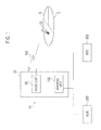
- Fig. 1 is an overall schematic configurational view of a radio base station system 10 according to this embodiment.
- the radio base station system 10 includes a BRE 30, an MDE 200, and a BDE 300.
- the BRE 30 includes a radio unit 50 and a sharing unit 100.
- the radio unit 50 transmits and receives a radio signal RS in a predetermined radio frequency band to and from a mobile station 20.
- the radio unit 50 includes a plurality of radio transmission and reception units (OA-RA: Open Air Receiver Amplifier) and forms a cover area C in which the mobile station 20 can perform radio communications with the radio unit 50.
- the cover area C includes a plurality of sectors S (sector 1 to sector 6 in this embodiment).
- the sharing unit 100 is connected to the radio unit 50.
- the sharing unit 100 is connected to the MDE 200 and the BDE 300.
- the sharing unit 100 relays a signal (hereinafter RF signal) in a radio frequency band transmitted and received by the MDE 200.
- the sharing unit 100 relays a digital signal in accordance with CPRI transmitted and received by the BDE 300.
- the BRE 30 forms a radio equipment device sharing device.
- the RF signal transmitted and received by the MDE 200 and the digital signal transmitted and received by the BDE 300 include information transmitted and received by a user (mobile station 20) and the like.
- the BRE 30 functions as a Radio Equipment (RE) device defined by the Common Public Radio Interface (CPRI) for the BDE 300.
- RE Radio Equipment
- CPRI Common Public Radio Interface
- the MDE 200 is a monitoring controller for a third generation mobile communication system (3G) defined by 3GPP and monitors and controls the radio unit 50.
- the MDE 200 forms a first monitoring controller that monitors the radio unit 50 in accordance with a first radio communication system (3G).
- the radio unit 50 transmits and receives a radio signal RS based on the control by the MDE 200.
- the BDE 300 is a monitoring controller for a Long Term Evolution (LTE) defined by the 3GPP and monitors and controls the radio unit 50.
- LTE Long Term Evolution
- the BDE 300 forms a second monitoring controller that monitors the radio unit 50 in accordance with a second radio communication system (LTE) different from the first radio communication system.
- LTE radio communication system
- the BDE 300 functions as the Radio Equipment Control (REC) defined by the CPRI.
- a radio frequency band (e.g., 2 GHz band) used in the 3G overlaps with a radio frequency band used in the LTE.
- Fig. 2 is a configurational diagram of functional blocks of the BRE 30 forming the radio equipment device sharing device in this embodiment.
- the BRE 30 includes the radio unit 50, a relay processing unit 101, a 3G RF-INF 103, a TRX-IF 105, a sector monitoring unit 107, and a PORT-INF 110.
- the relay processing unit 101 relays an RF signal transmitted and received by the MDE 200 and a digital signal transmitted and received by the BDE 300.
- the relay processing unit 101 relays the RF signal to the radio unit 50 received from the MDE 200 through the 3G RF-INF 103. Similarly, the relay processing unit 101 relays the RF signal addressed to the MDE 200 and received from the radio unit 50 to the MDE 200.
- the relay processing unit 101 converts the digital signal received from the BDE 300 through the TRX-IF 105 into the RF signal and relays the signal to the radio unit 50. Similarly, the relay processing unit 101 converts the RF signal addressed to the BDE 300 received from the radio unit 50 into the digital signal and relays the signal to the BDE 300.
- the 3G RF-INF 103 is an interface for transmitting and receiving an RF signal that is a signal in a radio frequency band to and from the MDE 200.
- the 3G RF-INF 103 forms an RF interface.
- a coaxial cable and the like through which the RF signal can be transmitted is connected to the 3G RF-INF 103.
- the TRX-IF 105 is an interface for transmitting and receiving a digital signal in accordance with the CPRI to and from the BDE 300.
- the TRX-IF 105 forms a digital signal interface.
- An optical cable through which the digital signal can be transmitted is connected to the TRX-IF 105.
- the sector monitoring unit 107 monitors a state of a sector S (see Fig. 1 ) in the cover area C formed by the radio unit 50. Specifically, the sector monitoring unit 107 acquires a signal indicating a state of a plurality of radio transmission and reception units (OA-RA) included in the radio unit 50.
- the radio transmission and reception units respectively correspond to the sectors (sector 1 to sector 6 in this embodiment).
- the sector monitoring unit 107 outputs to the TRX-IF 105 and the PORT-INF 110, the acquired state of each of the radio transmission and reception unit as a state (normal or failed) of each of the sectors.
- the state of each of the sectors inputted to the TRX-IF 105 is notified to the BDE 300 by using C&M Plane Data Channels (see CPRI Specification V4.0 Section 4.2.7.7). Meanwhile, the state of each of the sectors inputted to the PORT-INF 110 is notified to the MDE 200 as a ground signal.
- the PORT-INF 110 is an interface for notifying the MDE 200 of a monitoring signal indicating a state of the radio unit 50, specifically, the signal indicating the state of each of the sectors.
- the PORT-INF 110 forms a monitoring signal interface.
- a signal transmitted and received through the PORT-INF 110 is a ground signal.
- the "ground signal” includes switching a relay contact between close (loop) and open or between a grounded state and opened state based on the state (normal or failed) of the sector.
- the "ground signal” may that for performing switching between a state where a predetermined voltage is applied and the opened state based on the state of the sector.
- the signal transmitted and received through the PORT-INF 110 is of a type different from those of signals transmitted and received by the 3G RF-INF 103 (RF interface) and the TRX-IF 105 (digital signal interface).
- Fig. 3 is a configurational view of the PORT-INF 110 forming the monitoring signal interface in this embodiment.
- the PORT-INF 110 includes a relay control unit 111, relays 113 1 to 113 6 , and a connector 115.
- the relay controller 111 controls the relays 113 1 to 113 6 based on the states of the sectors outputted from the sector monitoring unit 107. Specifically, the relay control unit 111 performs the following control. When the state of a sector is normal, a relay corresponding thereto is turned to a closed state (ON) whereas when a sector is in failure, a relay corresponding thereto is turned to an opened state (OFF).
- the relay 113 1 corresponds to the sector 1.
- the relays 113 2 to 113 6 correspond to the sector 2 to sector 6, respectively.
- the connector 115 is used for the connection to terminals (A, B) of the relays 113 1 to 113 6 .
- a cable including equal to or more than six pairs of core wires connecting the MDE 200 and the PORT-INF 110 is connected to the connector 115.
- This embodiment is configured in such a manner that when a relay is closed, current flows through a circuit (not shown) connected to the relay.
- Fig. 4 shows an example of an operation for obtaining the state of the radio unit 50 performed between the BRE 30 and the BDE 300.
- the BDE 300 transmits to the BRE 30, a state report request for an RE card (not shown) installed in the radio unit 50.
- the BRE 30 transmits a state report response for the RE card to the BDE 300 based on the state report request received from the BDE 300.
- the state repot request and the state report response are executed using the C&M Plane Data in accordance with the CPRI Specification.
- the state report response includes a state of each RE card (in operation/used/failed) and a cause of failure.
- Fig. 5 shows a table defining operations for notifying sector states performed between the BRE 30 and the MDE 200.
- Connector numbers (1 to 6) shown in Fig. 5 respectively correspond to the relays 113 1 to 113 6 (see Fig. 3 ).
- the connector number 1 (the relay 113 1 ) is used for failure notification for the sector 1.
- the connector numbers 2 to 6 (113 2 to 113 6 ) are used for failure notification for the sector 2 to the sector 6, respectively.
- the state of the BRE 30 can be notified to the MDE 200 even when the BRE 30 and the MDE 200 are connected with each other through an RF interface (3G RF-INF 103) for transmitting and receiving an RF signal generated through a modulation of user information because a monitoring signal interface (PORT-INF 110) using a ground signal is provided.
- an RF interface 3G RF-INF 103
- PORT-INF 110 monitoring signal interface
- a monitoring signal interface using a widely used ground signal is used.
- the state of the BRE 30 can be notified to the MDE 200 without upgrading the MDE 200.
- the BRE 30 allows the BDE 300 to perform state monitoring of the BRE 30 in accordance with the CPRI.
- a plurality of monitoring controllers in different radio communication systems to monitor the state of the radio unit 50 (RE) even in a case where the radio unit 50 is shared by the monitoring controllers, and where the radio unit 50 transmits and receives, to and from one of the monitoring controllers (BDE 300), the digital signal in accordance with the CPRI, and transmits and receives the RF signal to and from another one of the monitoring controllers (MDE 200).
- the description is given with the 3G and the LTE as examples.
- the used radio communication systems are not limited to these and a GSM and the LTE may be used.
- the functions of the BRE 30 may be implemented by hardware or a software module implemented by a processor. Alternatively, the functions may be implemented by a combination of hardware and software.
- the present invention can provide a radio equipment device sharing device capable of allowing plural monitoring controllers (RECs) in different communication systems to monitor the state of a radio equipment (RE) device even in a case where the radio equipment (RE) device is shared by the RECs, and where the radio equipment device sharing device transmits and receives, to and from one of the RECs, a digital signal in accordance with a standardized interface specification for connecting the RE and the REC, and transmits and receives an RF signal to and from another one of the RECs, and thus is useful in radio communications and the like.
- RECs monitoring controllers
Landscapes
- Engineering & Computer Science (AREA)
- Computer Networks & Wireless Communication (AREA)
- Signal Processing (AREA)
- Mobile Radio Communication Systems (AREA)
- Telephone Function (AREA)
Abstract
In a BRE300, an RF interface for transmitting and receiving an RF signal is used for communication with a MDE 200 and a digital signal interface for transmitting and receiving a digital signal in accordance with CPRI is used for communication with BDE 300. The BRE 300 includes a monitoring signal interface configured to notify the MDE 200 of a monitoring signal indicating a state of the radio unit 50. The signal transmitted and received through the monitoring signal interface is a ground signal and is of type different from types of signals transmitted and received by the RF interface and the digital signal interface.
Description
- The present invention relates to a radio equipment device sharing device that allows a radio equipment (RE) device to be shared by a plurality of monitoring controllers (REC).
- Recently, Common Public Radio Interface (CPRI) has been specified as the standard interface specification between a radio equipment (RE) device that transmits and receives a radio signal to and from a mobile station and a monitoring controller (REC: Radio Equipment Control) that controls the radio equipment device and does the like (see, Non-Patent
Document 1, for example). - In accordance with the interface specification, compatibility can be secured for allowing an RE and an REC manufactured by different vendors to be easily connected to each other.
- In terms of mobile communication systems, a transition period to a new radio communication method includes a period where there are both of a system based on a conventional radio communication method, e.g., a third generation mobile communication system (hereinafter, 3G) defined by 3GPP, and a system based on the new radio communication method, e. g. , a Long Term Evolution (hereinafter, LTE) defined by the 3GPP.
- Here, while an RE can be used in both 3G and LTE, an REC is dedicated to each system. Thus, an RE/REC system supporting the 3G and an RE/REC system supporting the LTE need to be prepared to connect the RE and the REC in accordance with the CPRI. Therefore, there arises a problem that the RE cannot be efficiently used.
- To address this, studies have been made on a radio base station system including a radio equipment device sharing device (BRE: Base station Radio processing Equipment) provided between an RE and multiple RECs respectively supporting the systems, and configured to allow the multiple RECs to share the RE. A conventional system based on a conventional radio communication system (3G) does not necessarily support the CPRI. For this reason, when such a radio equipment device sharing device is provided, information transmitted and received by a user (mobile station) may be modulated into a signal (hereinafter, RF signal) in a radio frequency band (RF band) and then is transmitted and received between the REC (MDE: Modulation and Demodulation Equipment) for the 3G and the radio equipment device sharing device in some cases. On the other hand, a digital signal in accordance with the CPRI is transmitted and received between the REC (BDE: Base station Digital processing Equipment) for the LTE and the radio equipment device sharing device.
- NON-PATENT DOCUMENT 1: CPRI Specification V4.0, [online], June 30th, 2008 [searched on April 1st, 2008], Internet <URL: http://www.cpri.info/downloads/CPRI_v_4_0_2008-06-30.pdf>
- However, the above-described radio equipment device sharing device has the following problem. Specifically, a signal transmitted and received between the REC (MDE) for the 3G and the radio equipment device sharing device is an RF signal and failure information of the RE (e.g., sector failure) is difficult to multiplex on the RF signal. Thus, there is a problem that the failure information cannot be notified to the MDE.
- Accordingly, an objective of the present invention is to provide a radio equipment device sharing device capable of allowing plural monitoring controllers (RECs) in different communication systems to monitor the state of a radio equipment (RE) device even in a case where the radio equipment (RE) device is shared by the RECs, and where the radio equipment device sharing device transmits and receives, to and from one of the RECs, a digital signal in accordance with a standardized interface specification for connecting the RE and the REC, and transmits and receives an RF signal to and from another one of the RECs.
- The present invention has the following features to solve the problems described above. The first feature of the present invention is summarized in that a radio equipment device sharing device (BRE 30) comprising a radio unit (radio unit 50) configured to transmit and receive a radio signal (radio signal RS) to and from a mobile station (mobile station 20), wherein the radio equipment device sharing device is connected to: a first monitoring controller (MDE 200) configured to monitor and control the radio unit in accordance with a first radio communication system (3G); and a second monitoring controller (BDE 300) configured to monitor and control the radio unit in accordance with a second radio communication system (LTE) different from the first radio communication system, an RF interface (RF-INF103) for transmitting and receiving an RF signal that is a signal in a radio frequency band is used for communication between the radio equipment device sharing device and the first monitoring controller, whereas a digital signal interface (TRX-INF105) for transmitting and receiving a digital signal in accordance with a standardized interface specification for connecting a radio equipment device (CPRI) and the second monitoring controller is used for communication between the radio equipment device sharing device and the second monitoring controller, the radio equipment device sharing device relays the RF signal transmitted and to be received by the first monitoring controller and the digital signal transmitted and to be received by the second monitoring controller, the radio equipment device sharing device includes a monitoring signal interface (PORT-INF110) configured to notify the first monitoring controller of a monitoring signal indicating a state of the radio unit, and the signal transmitted and received through the monitoring signal interface is of a type different from types of signals transmitted and received by the RF interface and the digital signal interface.
- The second feature is according to the first feature and is summarized in that the signal transmitted and received through the monitoring signal interface is a ground signal.
- The Third feature is according to the first feature and is summarized in that a radio frequency band used in the first radio communication system overlaps with a radio frequency band used in the second radio communication method.
- The fourth feature is according to the first feature and is summarized in that the monitoring signal is a signal indicating a state of a sector formed by the radio unit.
-
- [
Fig. 1] Fig. 1 is an overall schematic configurational view of a radiobase station system 10 according to an embodiment of the present invention. - [
Fig. 2] Fig. 2 is a configuration diagram of functional blocks of aBRE 30 according to the embodiment of the present invention. - [
Fig. 3] Fig. 3 is a configurational view of a PORT-INF 110 according to the embodiment of the present invention. - [
Fig. 4] Fig. 4 is a diagram showing an example of an operation for acquiring a state of aradio unit 50 performed between the BRE 30 and aBDE 300 according to the embodiment of the present invention. - [
Fig. 5] Fig. 5 is a diagram showing a table defining notification operations of sector states performed between the BRE 30 and an MDE 200 according to the embodiment of the present invention. - Next, an embodiment of the present invention is described. Specifically, descriptions are given on (1) Overall Schematic Configuration of Radio Base Station System, (2) Functional Block Configuration of Radio Equipment Device Sharing Device, (3) Configuration of Monitoring Signal Interface, (4) Operation of Radio Equipment Device Sharing Device, (5) Advantageous Effect, and (6) Other Embodiment.
- Note that, in the following description of the drawings, same or similar reference signs denote same or similar elements and portions. In addition, it should be noted that the drawings are schematic and ratios of dimensions and the like are different from actual ones.
- Therefore, specific dimensions and the like should be determined in consideration of the following description. Moreover, the drawings also include portions having different dimensional relationships and ratios from each other.
-
Fig. 1 is an overall schematic configurational view of a radiobase station system 10 according to this embodiment. As shown inFig. 1 , the radiobase station system 10 includes a BRE 30, an MDE 200, and a BDE 300. - The BRE 30 includes a
radio unit 50 and asharing unit 100. Theradio unit 50 transmits and receives a radio signal RS in a predetermined radio frequency band to and from amobile station 20. Specifically, theradio unit 50 includes a plurality of radio transmission and reception units (OA-RA: Open Air Receiver Amplifier) and forms a cover area C in which themobile station 20 can perform radio communications with theradio unit 50. The cover area C includes a plurality of sectors S (sector 1 tosector 6 in this embodiment). - The sharing
unit 100 is connected to theradio unit 50. The sharingunit 100 is connected to the MDE 200 and the BDE 300. The sharingunit 100 relays a signal (hereinafter RF signal) in a radio frequency band transmitted and received by the MDE 200. The sharingunit 100 relays a digital signal in accordance with CPRI transmitted and received by the BDE 300. In this embodiment, the BRE 30 forms a radio equipment device sharing device. The RF signal transmitted and received by the MDE 200 and the digital signal transmitted and received by the BDE 300 include information transmitted and received by a user (mobile station 20) and the like. - In this embodiment, the BRE 30 functions as a Radio Equipment (RE) device defined by the Common Public Radio Interface (CPRI) for the BDE 300.
- The MDE 200 is a monitoring controller for a third generation mobile communication system (3G) defined by 3GPP and monitors and controls the
radio unit 50. In this embodiment, the MDE 200 forms a first monitoring controller that monitors theradio unit 50 in accordance with a first radio communication system (3G). Theradio unit 50 transmits and receives a radio signal RS based on the control by the MDE 200. - The BDE 300 is a monitoring controller for a Long Term Evolution (LTE) defined by the 3GPP and monitors and controls the
radio unit 50. In this embodiment, the BDE 300 forms a second monitoring controller that monitors theradio unit 50 in accordance with a second radio communication system (LTE) different from the first radio communication system. The BDE 300 functions as the Radio Equipment Control (REC) defined by the CPRI. - In this embodiment, a radio frequency band (e.g., 2 GHz band) used in the 3G overlaps with a radio frequency band used in the LTE.
-
Fig. 2 is a configurational diagram of functional blocks of the BRE 30 forming the radio equipment device sharing device in this embodiment. As shown inFig. 2 , the BRE 30 includes theradio unit 50, arelay processing unit 101, a 3G RF-INF 103, a TRX-IF 105, asector monitoring unit 107, and a PORT-INF 110. - The
relay processing unit 101 relays an RF signal transmitted and received by the MDE 200 and a digital signal transmitted and received by the BDE 300. - Specifically, the
relay processing unit 101 relays the RF signal to theradio unit 50 received from the MDE 200 through the 3G RF-INF 103. Similarly, therelay processing unit 101 relays the RF signal addressed to the MDE 200 and received from theradio unit 50 to the MDE 200. - The
relay processing unit 101 converts the digital signal received from theBDE 300 through the TRX-IF 105 into the RF signal and relays the signal to theradio unit 50. Similarly, therelay processing unit 101 converts the RF signal addressed to theBDE 300 received from theradio unit 50 into the digital signal and relays the signal to theBDE 300. - The 3G RF-
INF 103 is an interface for transmitting and receiving an RF signal that is a signal in a radio frequency band to and from theMDE 200. In this embodiment, the 3G RF-INF 103 forms an RF interface. A coaxial cable and the like through which the RF signal can be transmitted is connected to the 3G RF-INF 103. - The TRX-
IF 105 is an interface for transmitting and receiving a digital signal in accordance with the CPRI to and from theBDE 300. In this embodiment, the TRX-IF 105 forms a digital signal interface. An optical cable through which the digital signal can be transmitted is connected to the TRX-IF 105. - The
sector monitoring unit 107 monitors a state of a sector S (seeFig. 1 ) in the cover area C formed by theradio unit 50. Specifically, thesector monitoring unit 107 acquires a signal indicating a state of a plurality of radio transmission and reception units (OA-RA) included in theradio unit 50. The radio transmission and reception units respectively correspond to the sectors (sector 1 tosector 6 in this embodiment). - The
sector monitoring unit 107 outputs to the TRX-IF 105 and the PORT-INF 110, the acquired state of each of the radio transmission and reception unit as a state (normal or failed) of each of the sectors. The state of each of the sectors inputted to the TRX-IF 105 is notified to theBDE 300 by using C&M Plane Data Channels (see CPRI Specification V4.0 Section 4.2.7.7). Meanwhile, the state of each of the sectors inputted to the PORT-INF 110 is notified to theMDE 200 as a ground signal. - The PORT-
INF 110 is an interface for notifying theMDE 200 of a monitoring signal indicating a state of theradio unit 50, specifically, the signal indicating the state of each of the sectors. In this embodiment, the PORT-INF 110 forms a monitoring signal interface. - In this embodiment, a signal transmitted and received through the PORT-
INF 110 is a ground signal. Here, the "ground signal" includes switching a relay contact between close (loop) and open or between a grounded state and opened state based on the state (normal or failed) of the sector. Alternatively, the "ground signal" may that for performing switching between a state where a predetermined voltage is applied and the opened state based on the state of the sector. - That is, the signal transmitted and received through the PORT-
INF 110 is of a type different from those of signals transmitted and received by the 3G RF-INF 103 (RF interface) and the TRX-IF 105 (digital signal interface). -
Fig. 3 is a configurational view of the PORT-INF 110 forming the monitoring signal interface in this embodiment. As shown inFig. 3 , the PORT-INF 110 includes arelay control unit 111, relays 1131 to 1136, and aconnector 115. - The
relay controller 111 controls the relays 1131 to 1136 based on the states of the sectors outputted from thesector monitoring unit 107. Specifically, therelay control unit 111 performs the following control. When the state of a sector is normal, a relay corresponding thereto is turned to a closed state (ON) whereas when a sector is in failure, a relay corresponding thereto is turned to an opened state (OFF). - The relay 1131 corresponds to the
sector 1. Similarly, the relays 1132 to 1136 correspond to thesector 2 tosector 6, respectively. - The
connector 115 is used for the connection to terminals (A, B) of the relays 1131 to 1136. A cable including equal to or more than six pairs of core wires connecting theMDE 200 and the PORT-INF 110 is connected to theconnector 115. - This embodiment is configured in such a manner that when a relay is closed, current flows through a circuit (not shown) connected to the relay.
- Next, an operation of the
BRE 30 forming the radio equipment device sharing device will be described. Specifically, descriptions are given on (4.1) Operation for Acquiring State ofRadio Unit 50 Performed betweenBRE 30 andBDE 300, and (4.2) Operation for Notifying Sector State Performed betweenBRE 30 andMDE 200. -
Fig. 4 shows an example of an operation for obtaining the state of theradio unit 50 performed between theBRE 30 and theBDE 300. As shown inFig. 4 , theBDE 300 transmits to theBRE 30, a state report request for an RE card (not shown) installed in theradio unit 50. - The
BRE 30 transmits a state report response for the RE card to theBDE 300 based on the state report request received from theBDE 300. As described above, the state repot request and the state report response are executed using the C&M Plane Data in accordance with the CPRI Specification. - As shown in
Fig. 4 , the state report response includes a state of each RE card (in operation/used/failed) and a cause of failure. -
Fig. 5 shows a table defining operations for notifying sector states performed between theBRE 30 and theMDE 200. Connector numbers (1 to 6) shown inFig. 5 respectively correspond to the relays 1131 to 1136 (seeFig. 3 ). For example, the connector number 1 (the relay 1131) is used for failure notification for thesector 1. Similarly, theconnector numbers 2 to 6 (1132 to 1136) are used for failure notification for thesector 2 to thesector 6, respectively. - With the
BRE 30, the state of theBRE 30 can be notified to theMDE 200 even when theBRE 30 and theMDE 200 are connected with each other through an RF interface (3G RF-INF 103) for transmitting and receiving an RF signal generated through a modulation of user information because a monitoring signal interface (PORT-INF 110) using a ground signal is provided. Thus, the failure of theBRE 30 can be addressed promptly. Accordingly, effect of the failure on the provision of a service can be minimized. - According to the
BRE 30, a monitoring signal interface using a widely used ground signal is used. Thus, the state of theBRE 30 can be notified to theMDE 200 without upgrading theMDE 200. Moreover, theBRE 30 allows theBDE 300 to perform state monitoring of theBRE 30 in accordance with the CPRI. - Specifically, with the
BRE 30, a plurality of monitoring controllers (MDE 200 and BDE 300) in different radio communication systems to monitor the state of the radio unit 50 (RE) even in a case where theradio unit 50 is shared by the monitoring controllers, and where theradio unit 50 transmits and receives, to and from one of the monitoring controllers (BDE 300), the digital signal in accordance with the CPRI, and transmits and receives the RF signal to and from another one of the monitoring controllers (MDE 200). - As described above, the details of the present invention have been disclosed by using the embodiment of the present invention. However, it should not be understood that the description and drawings which constitute part of this disclosure limit the present invention. From this disclosure, various alternative embodiments, examples, and operation techniques will be easily found by those skilled in the art.
- For example, in the above-described embodiment of the present invention, the description is given with the 3G and the LTE as examples. The used radio communication systems are not limited to these and a GSM and the LTE may be used.
- The functions of the
BRE 30 may be implemented by hardware or a software module implemented by a processor. Alternatively, the functions may be implemented by a combination of hardware and software. - As described above, the present invention naturally includes various embodiments which are not described herein. Accordingly, the technical scope of the present invention should be determined only by the matters to define the invention in the scope of claims regarded as appropriate based on the description.
- Note that the entire content of Japanese Patent Application No.
2009-298417 (filed on December 28, 2009 - The present invention can provide a radio equipment device sharing device capable of allowing plural monitoring controllers (RECs) in different communication systems to monitor the state of a radio equipment (RE) device even in a case where the radio equipment (RE) device is shared by the RECs, and where the radio equipment device sharing device transmits and receives, to and from one of the RECs, a digital signal in accordance with a standardized interface specification for connecting the RE and the REC, and transmits and receives an RF signal to and from another one of the RECs, and thus is useful in radio communications and the like.
-
- 10
- radio base station system
- 20
- mobile station
- 30
- BRE
- 50
- radio unit
- 100
- sharing unit
- 101
- relay processing unit
- 103
- 3G RF-INF
- 105
- TRX-IF
- 107
- sector monitoring unit
- 110
- PORT-INF
- 111
- relay control unit
- 1131 to 1136
- relays
- 115
- connector
- 300
- BDE
- 200
- MDE
- C
- cover area
- RS
- radio signal
- S
- sector
Claims (4)
- A radio equipment device sharing device comprising a radio unit configured to transmit and receive a radio signal to and from a mobile station, wherein
the radio equipment device sharing device is connected to:a first monitoring controller configured to monitor and control the radio unit in accordance with a first radio communication system; anda second monitoring controller configured to monitor and control the radio unit in accordance with a second radio communication system different from the first radio communication system,an RF interface for transmitting and receiving an RF signal that is a signal in a radio frequency band is used for communication between the radio equipment device sharing device and the first monitoring controller, whereas a digital signal interface for transmitting and receiving a digital signal in accordance with a standardized interface specification for connecting a radio equipment device and the second monitoring controller is used for communication between the radio equipment device sharing device and the second monitoring controller,
the radio equipment device sharing device relays the RF signal transmitted and to be received by the first monitoring controller and the digital signal transmitted and to be received by the second monitoring controller,
the radio equipment device sharing device comprises a monitoring signal interface configured to notify the first monitoring controller of a monitoring signal indicating a state of the radio unit, and
the signal transmitted and received through the monitoring signal interface is of a type different from types of signals transmitted and received by the RF interface and the digital signal interface. - The radio equipment device sharing device according to claim 1, wherein the signal transmitted and received through the monitoring signal interface is a ground signal.
- The radio equipment device sharing device according to claim 1, wherein a radio frequency band used in the first radio communication system overlaps with a radio frequency band used in the second radio communication method.
- The radio equipment device sharing device according to claim 3, wherein the monitoring signal is a signal indicating a state of a sector formed by the radio unit.
Applications Claiming Priority (2)
| Application Number | Priority Date | Filing Date | Title |
|---|---|---|---|
| JP2009298417A JP5391057B2 (en) | 2009-12-28 | 2009-12-28 | Wireless device shared device |
| PCT/JP2010/073584 WO2011081142A1 (en) | 2009-12-28 | 2010-12-27 | Wireless device common use device |
Publications (1)
| Publication Number | Publication Date |
|---|---|
| EP2521420A1 true EP2521420A1 (en) | 2012-11-07 |
Family
ID=44226546
Family Applications (1)
| Application Number | Title | Priority Date | Filing Date |
|---|---|---|---|
| EP10840998A Withdrawn EP2521420A1 (en) | 2009-12-28 | 2010-12-27 | Wireless device common use device |
Country Status (5)
| Country | Link |
|---|---|
| US (1) | US20130005318A1 (en) |
| EP (1) | EP2521420A1 (en) |
| JP (1) | JP5391057B2 (en) |
| CN (1) | CN102687585A (en) |
| WO (1) | WO2011081142A1 (en) |
Families Citing this family (5)
| Publication number | Priority date | Publication date | Assignee | Title |
|---|---|---|---|---|
| JP2013065977A (en) * | 2011-09-15 | 2013-04-11 | Nec Saitama Ltd | Radio base station system and communication control method |
| JP6467294B2 (en) * | 2015-06-05 | 2019-02-13 | 株式会社Nttドコモ | Communication system and relay device |
| MX2018014697A (en) | 2016-06-01 | 2019-09-13 | Isco Int Llc | METHOD AND APPARATUS TO CARRY OUT SIGNAL CONDITIONING TO MITIGATE THE INTERFERENCE DETECTED IN A COMMUNICATION SYSTEM. |
| EP3632013B1 (en) | 2017-05-31 | 2022-05-11 | Fraunhofer-Gesellschaft zur Förderung der angewandten Forschung e.V. | Apparatus, measurement system for testing an apparatus and methods for operating the same |
| US10284313B2 (en) * | 2017-08-09 | 2019-05-07 | Isco International, Llc | Method and apparatus for monitoring, detecting, testing, diagnosing and/or mitigating interference in a communication system |
Family Cites Families (17)
| Publication number | Priority date | Publication date | Assignee | Title |
|---|---|---|---|---|
| JPS63131645A (en) * | 1986-11-20 | 1988-06-03 | Fujitsu Ltd | Ineffective start preventing system for total dial network |
| JPH02301297A (en) * | 1989-05-15 | 1990-12-13 | Fujitsu Ltd | Trunk line monitor control method |
| FI98974C (en) * | 1993-09-24 | 1997-09-10 | Nokia Telecommunications Oy | Procedure for securing the function of a base station divided into sectors as well as a base station |
| JP3736211B2 (en) * | 1999-07-05 | 2006-01-18 | 日本電気株式会社 | Radio base station apparatus and radio function stop prevention method |
| JP2004312131A (en) * | 2003-04-03 | 2004-11-04 | Matsushita Electric Ind Co Ltd | Radio base station resource allocation method and radio base station |
| CN1956564A (en) * | 2005-10-26 | 2007-05-02 | Ut斯达康通讯有限公司 | Multi-protocol signal transmission method based on CPRI in distributed base station system and its device |
| JP2007312185A (en) * | 2006-05-19 | 2007-11-29 | Nec Corp | Radio base station system |
| EP2127414A2 (en) * | 2007-01-29 | 2009-12-02 | Nokia Corporation | Apparatus, method and computer program product providing inter-operatibility between legacy and other radio network subsystem |
| JP2008227618A (en) * | 2007-03-08 | 2008-09-25 | Nec Saitama Ltd | Base station radio apparatus, mobile unit communication system, and control method for base station radio apparatus |
| EP2139243B1 (en) * | 2007-03-16 | 2014-07-30 | Fujitsu Limited | Base station, wireless control device, and wireless device |
| WO2008120297A1 (en) * | 2007-03-28 | 2008-10-09 | Fujitsu Limited | Method for data communication between radio control equipment and radio equipment, radio control equipment and radio equipment |
| JP5157550B2 (en) * | 2008-03-17 | 2013-03-06 | 日本電気株式会社 | Signal distribution device, radio device, and communication system |
| US8050296B2 (en) * | 2008-03-31 | 2011-11-01 | Telefonaktiebolaget Lm Ericsson (Publ) | Radio equipment (RE)-based synchronization |
| CN101309465B (en) * | 2008-05-23 | 2012-07-04 | 华为技术有限公司 | Wireless Base Station Equipment, Wireless Device Controllers, and Wireless Devices |
| JP5243109B2 (en) | 2008-06-11 | 2013-07-24 | 東洋自動機株式会社 | Automatic bagging and packaging machine |
| US20100023282A1 (en) * | 2008-07-22 | 2010-01-28 | Sun Microsystem, Inc. | Characterizing a computer system using radiating electromagnetic signals monitored through an interface |
| CN102450046A (en) * | 2009-06-03 | 2012-05-09 | 华为技术有限公司 | Base station with a plurality of logical base stations |
-
2009
- 2009-12-28 JP JP2009298417A patent/JP5391057B2/en active Active
-
2010
- 2010-12-27 WO PCT/JP2010/073584 patent/WO2011081142A1/en not_active Ceased
- 2010-12-27 US US13/519,702 patent/US20130005318A1/en not_active Abandoned
- 2010-12-27 EP EP10840998A patent/EP2521420A1/en not_active Withdrawn
- 2010-12-27 CN CN2010800597205A patent/CN102687585A/en active Pending
Non-Patent Citations (1)
| Title |
|---|
| See references of WO2011081142A1 * |
Also Published As
| Publication number | Publication date |
|---|---|
| CN102687585A (en) | 2012-09-19 |
| JP5391057B2 (en) | 2014-01-15 |
| WO2011081142A1 (en) | 2011-07-07 |
| JP2011139327A (en) | 2011-07-14 |
| US20130005318A1 (en) | 2013-01-03 |
Similar Documents
| Publication | Publication Date | Title |
|---|---|---|
| CN109831223B (en) | Antenna multiplexing radio frequency device and terminal | |
| EP2432274B1 (en) | Method and device for data transmission | |
| US9320081B2 (en) | Radio communication apparatus, radio communication system and radio communication method | |
| EP2521420A1 (en) | Wireless device common use device | |
| KR101713930B1 (en) | Apparatus for transmitting of portable terminal and operation method thereof | |
| WO2017096637A1 (en) | Mimo satellite service terminal | |
| US10085237B2 (en) | Information processing device, wireless communication system, and information processing method | |
| CN105357737A (en) | Method and device for accessing WiFi device to wireless access point | |
| WO2012045370A1 (en) | Relay nodes | |
| US20250063491A1 (en) | Wireless communication device and wireless communication method | |
| US20190253147A1 (en) | Optical relay system and method for setting identification information of remote device in optical relay system | |
| EP1650903B1 (en) | Relay apparatus and relay method | |
| JP7417673B2 (en) | Signal processing method and device | |
| CN104770016B (en) | Non-access stratum message processing method, user equipment and network side equipment | |
| EP3013102B1 (en) | Method of handling serving cell becoming barred status, base station using the same, and user equipment using the same | |
| US9686325B2 (en) | Client terminal's tethering function is selectively turn on or off based on network connection | |
| JP4547221B2 (en) | Wireless base station equipment | |
| EP2190124A2 (en) | Radio communication apparatus, radio communication system and signal switching method | |
| KR20160131722A (en) | Telematics apparatus | |
| CN107612624B (en) | Communication relay device, communication relay system, method, and recording medium | |
| CN104010017A (en) | Terminal device and information processing method applied thereto | |
| WO2012047003A3 (en) | Method and device for transmitting/receiving data in a multi radio access system | |
| US9408068B2 (en) | Wireless communication apparatus and user equipment | |
| US11025306B2 (en) | Node unit and method of processing signal for distributed antenna system | |
| JP2013187598A (en) | Mobile communication system, base station device and mobile communication method |
Legal Events
| Date | Code | Title | Description |
|---|---|---|---|
| PUAI | Public reference made under article 153(3) epc to a published international application that has entered the european phase |
Free format text: ORIGINAL CODE: 0009012 |
|
| 17P | Request for examination filed |
Effective date: 20120712 |
|
| AK | Designated contracting states |
Kind code of ref document: A1 Designated state(s): AL AT BE BG CH CY CZ DE DK EE ES FI FR GB GR HR HU IE IS IT LI LT LU LV MC MK MT NL NO PL PT RO RS SE SI SK SM TR |
|
| DAX | Request for extension of the european patent (deleted) | ||
| STAA | Information on the status of an ep patent application or granted ep patent |
Free format text: STATUS: THE APPLICATION HAS BEEN WITHDRAWN |
|
| 18W | Application withdrawn |
Effective date: 20140109 |