EP2521267B1 - Method and apparatus for clock frequency division - Google Patents
Method and apparatus for clock frequency division Download PDFInfo
- Publication number
- EP2521267B1 EP2521267B1 EP10840419.5A EP10840419A EP2521267B1 EP 2521267 B1 EP2521267 B1 EP 2521267B1 EP 10840419 A EP10840419 A EP 10840419A EP 2521267 B1 EP2521267 B1 EP 2521267B1
- Authority
- EP
- European Patent Office
- Prior art keywords
- counting
- output
- indication
- frequency division
- accumulation
- Prior art date
- Legal status (The legal status is an assumption and is not a legal conclusion. Google has not performed a legal analysis and makes no representation as to the accuracy of the status listed.)
- Not-in-force
Links
Images



Classifications
-
- H—ELECTRICITY
- H03—ELECTRONIC CIRCUITRY
- H03K—PULSE TECHNIQUE
- H03K23/00—Pulse counters comprising counting chains; Frequency dividers comprising counting chains
- H03K23/64—Pulse counters comprising counting chains; Frequency dividers comprising counting chains with a base or radix other than a power of two
- H03K23/68—Pulse counters comprising counting chains; Frequency dividers comprising counting chains with a base or radix other than a power of two with a base which is a non-integer
-
- H—ELECTRICITY
- H03—ELECTRONIC CIRCUITRY
- H03K—PULSE TECHNIQUE
- H03K23/00—Pulse counters comprising counting chains; Frequency dividers comprising counting chains
- H03K23/64—Pulse counters comprising counting chains; Frequency dividers comprising counting chains with a base or radix other than a power of two
- H03K23/66—Pulse counters comprising counting chains; Frequency dividers comprising counting chains with a base or radix other than a power of two with a variable counting base, e.g. by presetting or by adding or suppressing pulses
- H03K23/667—Pulse counters comprising counting chains; Frequency dividers comprising counting chains with a base or radix other than a power of two with a variable counting base, e.g. by presetting or by adding or suppressing pulses by switching the base during a counting cycle
Definitions
- the present invention relates to a clock frequency division technology and more particularly to a method and an apparatus for clock frequency division.
- a frequency divider is required for the realization of clock frequency division, wherein the principle of the frequency divider isthat: each time when int( ⁇ b) is accumulated to be an integer, the frequency divider will add an input clock cycle Ti to frequency division time of an output clock cycle To according to Formula (1), which will shorten the output clock cycle To.
- ⁇ To ⁇ a + int ⁇ b * Ti + mod ⁇ b * Ti
- mod indicates a modulus function
- int indicates an integral function
- Ti represents the input clock cycle
- To represents the output clock cycle
- a is an integer portion after frequency division processing
- b is a decimal portion after frequency division processing.
- decimal portion b after the frequency division processing performed by the frequency divider is generally separated to be processed as an integer portion, which can be applied in network communications, such as the circuit emulation service of the packet switch network, so as to recover the clock of the source end at the receiver terminals.
- the integer portion ai and the decimal portion bi of the current frequency division are determined according to a current frequency division coefficient Ki in Formula (2), and a decimal scale threshold ci is determined according to the determined decimal portion bi.
- the decimal portion bi can be represented by an 8-bit, 12-bit, 16-bit or 32-bit value, etc., for example, if the decimal portion bi is a hexadecimal value, the corresponding decimal scale threshold ci is 3B9ACA00.
- the output clock frequency Fo is obtained based on the input clock frequency Fi according to the Formula (2) with the determined integer portion ai of the current frequency division, decimal portion bi of the current frequency division and current value of the decimal scale threshold ci of the current frequency division, so as to recover the clock frequency of the source end at the receiver terminals.
- the clock frequency division method above is completed on the basis of the hypothesis that the frequency division coefficient Ki is fixed. It can be used only in the situation where the frequency division coefficient is fixed; moreover, the decimal portion bi generally supports the value precision of 1 bit or 2 bits only.
- the frequency division precision is low, which makes it hard to meet the requirements of high frequency division precision, multi bit decimal portion and the dynamic adjustment of the frequency division coefficient in the clock recovery application in the communication field such as the packet switch network.
- the present invention provides a method and an apparatus for clock frequency division, which can raise the frequency division precision and meet the requirements of the dynamic adjustment of the frequency division coefficient.
- the present invention adopts the technical solution as follows.
- the present invention provides a method for clock frequency division, comprising: determining a current frequency division coefficient according to a current input clock frequency and a current output clock frequency, outputting an integer portion and a decimal portion of the frequency division coefficient, and obtaining a decimal scale threshold of the decimal portion; performing counting on input clock signals, and outputting a counting indication according to a counting result and the integer portion of the frequency division coefficient; performing accumulation on the decimal portion of the frequency division coefficient according to the counting indication, and outputting an accumulation indication according to an accumulation result and the decimal scale threshold; and controlling an output clock level according to the counting indication and the accumulation indication.
- the method comprises: performing counting on the input clock signals, and outputting an end indication of the current counting when the counting result is equal to the integer portion of the frequency division coefficient; performing accumulation on the decimal portion of the frequency division coefficient when the counting indication is the end indication of the counting, and outputting an end indication of the accumulation when the accumulation result is equal to the decimal scale threshold; and if the accumulation indication is the end indication of the accumulation, driving the output clock level to be high after delaying one clock cycle.
- the method further comprises: outputting an indication of half counting when the counting result is equal to integer digits of half of the integer portion of the frequency division coefficient; and driving the output clock level to be low when the counting indication is the indication of half counting.
- the step of controlling the output clock level according to the counting indication and the accumulation indication comprises: directly driving the output clock level to be high when the counting indication is the end indication of the counting and no end indication of the accumulation is output.
- the present invention also provides an apparatus for clock frequency division, comprising: a determination unit, configured to determine a current frequency division coefficient according to a current input clock frequency and a current output clock frequency, and respectively output an integer portion and a decimal portion of the current frequency division coefficient and a decimal scale threshold of the decimal portion; a counting unit, configured to perform counting on input clock signals, and output a counting indication according to a counting result and the integer portion of the current frequency division coefficient output by the determination unit; an accumulation unit, configured to perform accumulation on the decimal portion output by the determination unit according to the counting indication output by the counting unit, and output an accumulation indication according to the decimal scale threshold output by the determination unit and an accumulation result; and an output clock control unit, configured to control an output clock level according to the counting indication output by the counting unit and the accumulation indication output by the accumulation unit.
- the counting unit is configured to: perform counting on the input clock signals, and output an end indication of the current counting when the counting result is equal to the integer portion of the current frequency division coefficient output by the determination mit.
- the accumulation unit is configured to: perform accumulation on the decimal portion output by the determination unit when the end indication of the current counting is output by the counting unit; and output an end indication of the accumulation when the accumulation result is no less than the decimal scale threshold output by the determination unit.
- the counting unit is further configured to clear the counting result after outputting the end indication of the current counting.
- the counting unit is further configured to: output an indication of half counting when the counting result is equal to integer digits of half of the received integer portion of the current frequency division coefficient output by the determination unit.
- the output clock control unit is configured to: when receiving the end indication of the accumulation output by the accumulation unit, drive the output clock level to be high after delaying one clock cycle; when receiving the end indication of the counting output by the counting unit and the accumulation unit does not output the end indication of the accumulation, directly drive the output clock level to be high; when receiving the indication of half counting output by the counting unit, drive the output clock level to be low.
- the present invention determines the current frequency division coefficient in real time according to input clock signals and output clock information, performs counting on the input clock signals according to the integer portion and the decimal portion of the frequency division coefficient as well as the decimal scale threshold of the decimal portion, and then performs accumulation on the decimal portion according to the counting result, at last controls the output clock according to the counting result and the accumulation result, in thisway, the output signals can be dynamically adjusted according to the input signals.
- the bit width of the integer portion and the decimal portion of the frequency division coefficient and the decimal scale threshold of the decimal portion can be increased on demand, so that the precision of the frequency division coefficient can be adjusted.
- the method for clock frequency division mainly comprises the following steps.
- Step 101 a current frequency division coefficient is determined according to a current input clock frequency and a current output clock frequency, an integer portion and a decimal portion of the frequency division coefficient are output, and a decimal scale threshold of the decimal portion is obtained.
- the current frequency division coefficient can be determined in real time based on the actual frequencies of the input clock and output clock according to the actual application requirements.
- the decimal scale threshold can be obtained according to the number of bits of the decimal portion of the frequency division coefficient and the numeration system. For example, if the decimal portion of the frequency division coefficient adopts decimal system, the number of bits of the decimal portion are 2, thus the decimal scale threshold is 100.
- bit width of the integer portion and the decimal portion of the frequency division coefficient and the decimal scale threshold of the decimal portion can be increased on demand, so that the precision of the frequency division coefficientcan be adjusted.
- Step 102 counting is performed on input clock signals, and a counting indication is output according to the counting result and the integerportion of the frequency division coefficient.
- the process of outputting the counting indication according to the counting result and the integer portion of the frequency division coefficient can be specifically as follows: performing counting on the input clock signals and outputting an end indication of the current counting when the counting result is equal to the integer portion of the frequency division coefficient; outputting an indication of half counting when the counting result is equal to integer digits of half of the integer portion of the frequency division coefficient.
- the end indication of the current counting can be a high-level pulse signal generated when the counting result is equal to the integer portion of the frequency division coefficient, or can be a digit indication with the value being 1.
- the indication of half counting can be a high-level pulse signal generated when the counting result is equal to the integer digits of half of the integer portion of the frequency division coefficient, or can be a digit indication with the value being 1.
- Step 103 accumulation is performed on the decimal portion of the frequency division coefficient according to the counting indication, and an accumulation indication is output according to the accumulation result and the decimal scale threshold.
- the process of performing accumulation on the decimal portion of the frequency division coefficient according to the counting indication is specifically as follows: performing accumulation on the decimal portion of the frequency division coefficient when the counting indication is the end indication of the counting.
- the process of outputting the accumulation indication according to the accumulation result and the decimal scale threshold is specifically as follows: outputting the end indication of the accumulation when the accumulation result is equal to the decimal scale threshold.
- the end indication of the accumulation can be a high-level pulse signal generated when the accumulation result is equal to the decimal scale threshold, or can be a digit indication with the value being 1.
- Step 104 an output clock level is controlled according to the counting indication and the accumulation indication.
- the process of controlling the output clock level according to the counting indication and the accumulation indication is specifically as follows: when the accumulation indication is the end indication of the accumulation, driving the output clock level to be high after delaying one clock cycle; when the counting indication is the end indication of the counting and no end indication of the accumulation is output, directly driving the output clock level to be high; when the counting indication is the indication of half counting, driving the output clock level to be low.
- Step 102 specifically comprises the steps below.
- Step 201 the counting result cnt1 is cleared, the target value a of the counting is updated to be the integer portion ai of the current frequency division coefficient, and the value of the variable cnt1_div2 is updated to be the integer digits obtained by dividing the integerportion ai of the current frequency division coefficient by 2.
- the value of cnt1_div2 can be determined to be the integer obtained by adding 1 to the integer digits of half of ai, so as to ensure the duty ratio of the high & low levels of the output clock within one clock cycle keeps 50% during the whole frequency division processing if possible.
- Step 202 counting is performed on the input clock signals clki, each time when one input clock signal clki is detected, count once and add 1 to cnt1.
- Step 203 it is judged whether the value of cnt1 is equal to cnt1_div2, if equal, jump to Step 206; if not, enter Step 204.
- Step 204 it is judged whether the value of cnt1 is equal to a, if equal, enter Step 205; if not, return to Step 202,
- Step 205 an end indication cnt1_end, which is a high-level pulse signal, of the current counting is output, and return to Step 201.
- Step 206 an indication cnt1_half, which is a high-level pulse signal, of half counting is output, and return to Step 202.
- Step 103 the realization of the accumulation process in Step 103 comprises the steps below.
- Step 301 it is judged whether the decimal portion bi of the input current frequency division coefficient is equal to the current accumulation value b, and whether the input decimal scale threshold is equal to the threshold c of the current accumulation value, if equal, jump to Step 303; if not, enter Step 302.
- Step 302 the accumulation value b is updated to be the decimal portion bi of the current frequency division coefficient, the threshold c of the accumulation value is updated to be the current decimal scale threshold ci, and the accumulation result cnt2 is cleared.
- Step 303 it is judged whether the input cnt1_end is high level, if yes, enter Step 304; if not, end the current procedure.
- Step 304 b is accumulated onto the accumulation result cnt2.
- Step 305 it is judged whether cnt2 is not less than c, if cnt2 is not less than c, enter Step 306; if cnt2 is less than c, return to Step 303.
- Step 306 cnt2 is updated to be the difference obtained by subtracting c from cnt2, and an end indication cnt2_end, which is a high-level pulse signal, of the current counting is output, and return to Step 301.
- Step 104 the realization of the output clock level control process in Step 104 comprises the steps below.
- Step 401 it is judged whether cnt1_half is high level, if yes, enter Step 402; if not, jump to Step 403.
- Step 402 the level of the output clock clko is driven to be low, and return to Step 401.
- Step 403 it is judged whether cnt1_end is high level, if yes, enter Step 404; if not, return to Step 401.
- Step 404 it is judged whether cnt2_end is high level, if yes, enter Step 405; if not, jump to Step 406.
- Step 405 after delaying one clock cycle of an input clock clki, the level of the output clock clko is driven to be high, and return to Step 401.
- Step 406 the level of the output clock clko is directly driven to be high, and return to Step 401.
- the apparatus mainly comprises: a determination unit 51, a counting unit 52, an accumulation unit 53 and an output clock control unit 54, wherein the determination unit 51 is used to determine a current frequency division coefficient according to a current input clock frequency and a current output clock frequency, and output an integer portion ai and a decimal portion bi of the current frequency division coefficient and a decimal scale threshold ci of the decimal portion bi; the counting unit 52 is used to perform counting on the input clock (clki) signals and output a counting indication according to the integer portion ai of the current frequency division coefficient output by the determination unit51 and the counting result, the counting indication herein comprises an end indication cnt1_end of the counting and an indication cnt1_half of half counting; the accumulation unit 53 is used to perform accumulation on the decimal portion bi output by the determination unit 51 according to the counting indication output by the counting unit 52, and output an accumulation indication according to
- the counting unit 52 is specifically used to: perform counting on the input clock signals, and output the end indication cnt1_end of the counting when the counting result is equal to the integer portion of the current frequency division coefficient output by the determination unit 51.
- the counting unit 52 is also used to: clear the counting result after outputting theend indication cnt1_end of the counting.
- the counting unit 52 is also used to: output the indication cnt1_half of half counting when the counting result is equal to the integer digits of half of the integer portion of the current frequency division coefficient output by the determination unit 51.
- the accumulation unit 53 is specifically used to: perform accumulation on the decimal portion output by the determination unit 51 when the end indication cnt1_end of the counting is output by the counting unit 52; and output the end indication cnt2_end of the accumulation when the accumulation result is no less than the decimal scale threshold output by the determination unit 51.
- the output clock control unit 54 is specifically used to: when receiving the end indication cnt2_end of the accumulation output by the accumulation unit 53, drive the level of the output clock clko to be high after delaying one clock cycle; when receiving the end indication cnt1_end of the counting output by the counting unit 52 and the accumulation unit 53 does not output the end indication of the accumulation, directly drive the level of the output clock clko to be high; when receiving the indication cnt1_half of half counting output by the counting unit 52, drive the level of the output clock clko to be low.
Landscapes
- Manipulation Of Pulses (AREA)
- Synchronisation In Digital Transmission Systems (AREA)
- Stabilization Of Oscillater, Synchronisation, Frequency Synthesizers (AREA)
Description
- The present invention relates to a clock frequency division technology and more particularly to a method and an apparatus for clock frequency division.
- In the communication field, a frequency divider is required for the realization of clock frequency division, wherein the principle of the frequency divider isthat: each time when int(Σb) is accumulated to be an integer, the frequency divider will add an input clock cycle Ti to frequency division time of an output clock cycle To according to Formula (1), which will shorten the output clock cycle To.

- Wherein, mod indicates a modulus function, int indicates an integral function, Ti represents the input clock cycle, To represents the output clock cycle, a is an integer portion after frequency division processing, and b is a decimal portion after frequency division processing.
- In practical application, the decimal portion b after the frequency division processing performed by the frequency divider is generally separated to be processed as an integer portion, which can be applied in network communications, such as the circuit emulation service of the packet switch network, so as to recover the clock of the source end at the receiver terminals.
- At present, the specific method for decimal frequency division is as follows.
- First of all, the integer portion ai and the decimal portion bi of the current frequency division are determined according to a current frequency division coefficient Ki in Formula (2), and a decimal scale threshold ci is determined according to the determined decimal portion bi. As required by the precision, the decimal portion bi can be represented by an 8-bit, 12-bit, 16-bit or 32-bit value, etc., for example, if the decimal portion bi is a hexadecimal value, the corresponding decimal scale threshold ci is 3B9ACA00.

- Then the output clock frequency Fo is obtained based on the input clock frequency Fi according to the Formula (2) with the determined integer portion ai of the current frequency division, decimal portion bi of the current frequency division and current value of the decimal scale threshold ci of the current frequency division, so as to recover the clock frequency of the source end at the receiver terminals.
- The clock frequency division method above is completed on the basis of the hypothesis that the frequency division coefficient Ki is fixed. It can be used only in the situation where the frequency division coefficient is fixed; moreover, the decimal portion bi generally supports the value precision of 1 bit or 2 bits only. The frequency division precision is low, which makes it hard to meet the requirements of high frequency division precision, multi bit decimal portion and the dynamic adjustment of the frequency division coefficient in the clock recovery application in the communication field such as the packet switch network.
- Document
EP 1304804 discloses a fractional divider. However, the above mentioned problem still remains unsolved. - In view of the above, the present invention provides a method and an apparatus for clock frequency division, which can raise the frequency division precision and meet the requirements of the dynamic adjustment of the frequency division coefficient.
- The present invention adopts the technical solution as follows.
- The present invention provides a method for clock frequency division, comprising: determining a current frequency division coefficient according to a current input clock frequency and a current output clock frequency, outputting an integer portion and a decimal portion of the frequency division coefficient, and obtaining a decimal scale threshold of the decimal portion; performing counting on input clock signals, and outputting a counting indication according to a counting result and the integer portion of the frequency division coefficient; performing accumulation on the decimal portion of the frequency division coefficient according to the counting indication, and outputting an accumulation indication according to an accumulation result and the decimal scale threshold; and controlling an output clock level according to the counting indication and the accumulation indication.
- In the above solution, the method comprises: performing counting on the input clock signals, and outputting an end indication of the current counting when the counting result is equal to the integer portion of the frequency division coefficient; performing accumulation on the decimal portion of the frequency division coefficient when the counting indication is the end indication of the counting, and outputting an end indication of the accumulation when the accumulation result is equal to the decimal scale threshold; and if the accumulation indication is the end indication of the accumulation, driving the output clock level to be high after delaying one clock cycle.
- In the above solution, the method further comprises: outputting an indication of half counting when the counting result is equal to integer digits of half of the integer portion of the frequency division coefficient; and driving the output clock level to be low when the counting indication is the indication of half counting.
- In the above solution, the step of controlling the output clock level according to the counting indication and the accumulation indication comprises: directly driving the output clock level to be high when the counting indication is the end indication of the counting and no end indication of the accumulation is output.
- The present invention also provides an apparatus for clock frequency division, comprising: a determination unit, configured to determine a current frequency division coefficient according to a current input clock frequency and a current output clock frequency, and respectively output an integer portion and a decimal portion of the current frequency division coefficient and a decimal scale threshold of the decimal portion; a counting unit, configured to perform counting on input clock signals, and output a counting indication according to a counting result and the integer portion of the current frequency division coefficient output by the determination unit; an accumulation unit, configured to perform accumulation on the decimal portion output by the determination unit according to the counting indication output by the counting unit, and output an accumulation indication according to the decimal scale threshold output by the determination unit and an accumulation result; and an output clock control unit, configured to control an output clock level according to the counting indication output by the counting unit and the accumulation indication output by the accumulation unit.
- In the above solution, the counting unit is configured to: perform counting on the input clock signals, and output an end indication of the current counting when the counting result is equal to the integer portion of the current frequency division coefficient output by the determination mit.
- In the above solution, the accumulation unit is configured to: perform accumulation on the decimal portion output by the determination unit when the end indication of the current counting is output by the counting unit; and output an end indication of the accumulation when the accumulation result is no less than the decimal scale threshold output by the determination unit.
- In the above solution, the counting unit is further configured to clear the counting result after outputting the end indication of the current counting.
- In the above solution, the counting unit is further configured to: output an indication of half counting when the counting result is equal to integer digits of half of the received integer portion of the current frequency division coefficient output by the determination unit.
- In the above solution, the output clock control unit is configured to: when receiving the end indication of the accumulation output by the accumulation unit, drive the output clock level to be high after delaying one clock cycle; when receiving the end indication of the counting output by the counting unit and the accumulation unit does not output the end indication of the accumulation, directly drive the output clock level to be high; when receiving the indication of half counting output by the counting unit, drive the output clock level to be low.
- The present invention determines the current frequency division coefficient in real time according to input clock signals and output clock information, performs counting on the input clock signals according to the integer portion and the decimal portion of the frequency division coefficient as well as the decimal scale threshold of the decimal portion, and then performs accumulation on the decimal portion according to the counting result, at last controls the output clock according to the counting result and the accumulation result, in thisway, the output signals can be dynamically adjusted according to the input signals. In the present invention, the bit width of the integer portion and the decimal portion of the frequency division coefficient and the decimal scale threshold of the decimal portion can be increased on demand, so that the precision of the frequency division coefficient can be adjusted.
-
-
Fig. 1 is a schematic diagram of the realization procedure of the method for clock frequency division according to an embodiment of the present invention; -
Fig. 2 is a schematic diagram of the detailed procedure of the counting process realization according to an embodiment of the present invention; -
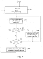
Fig. 3 is a schematic diagram of the detailed procedure of the accumulation process realization according to an embodiment of the present invention; -
Fig. 4 is a schematic diagram of the detailed procedure of the realization of the output clock control process according to an embodiment of the present invention; and -
Fig. 5 is a schematic diagram of the structure of the apparatus for clock frequency division according to an embodiment of the present invention. - The method for clock frequency division according to an embodiment of the present invention, as shown in
Fig. 1 , mainly comprises the following steps. - Step 101: a current frequency division coefficient is determined according to a current input clock frequency and a current output clock frequency, an integer portion and a decimal portion of the frequency division coefficient are output, and a decimal scale threshold of the decimal portion is obtained.
- In this step, the current frequency division coefficient can be determined in real time based on the actual frequencies of the input clock and output clock according to the actual application requirements.
- In the above, the decimal scale threshold can be obtained according to the number of bits of the decimal portion of the frequency division coefficient and the numeration system. For example, if the decimal portion of the frequency division coefficient adopts decimal system, the number of bits of the decimal portion are 2, thus the decimal scale threshold is 100.
- In practical application, the bit width of the integer portion and the decimal portion of the frequency division coefficient and the decimal scale threshold of the decimal portion can be increased on demand, so that the precision of the frequency division coefficientcan be adjusted.
- Step 102: counting is performed on input clock signals, and a counting indication is output according to the counting result and the integerportion of the frequency division coefficient.
- In this step, the process of outputting the counting indication according to the counting result and the integer portion of the frequency division coefficient can be specifically as follows: performing counting on the input clock signals and outputting an end indication of the current counting when the counting result is equal to the integer portion of the frequency division coefficient; outputting an indication of half counting when the counting result is equal to integer digits of half of the integer portion of the frequency division coefficient.
- Herein, the end indication of the current counting can be a high-level pulse signal generated when the counting result is equal to the integer portion of the frequency division coefficient, or can be a digit indication with the value being 1. The indication of half counting can be a high-level pulse signal generated when the counting result is equal to the integer digits of half of the integer portion of the frequency division coefficient, or can be a digit indication with the value being 1.
- Step 103: accumulation is performed on the decimal portion of the frequency division coefficient according to the counting indication, and an accumulation indication is output according to the accumulation result and the decimal scale threshold.
- In this step, the process of performing accumulation on the decimal portion of the frequency division coefficient according to the counting indication is specifically as follows: performing accumulation on the decimal portion of the frequency division coefficient when the counting indication is the end indication of the counting.
- In this step, the process of outputting the accumulation indication according to the accumulation result and the decimal scale threshold is specifically as follows: outputting the end indication of the accumulation when the accumulation result is equal to the decimal scale threshold.
- Herein, the end indication of the accumulation can be a high-level pulse signal generated when the accumulation result is equal to the decimal scale threshold, or can be a digit indication with the value being 1.
- Step 104: an output clock level is controlled according to the counting indication and the accumulation indication.
- In this step, the process of controlling the output clock level according to the counting indication and the accumulation indication is specifically as follows: when the accumulation indication is the end indication of the accumulation, driving the output clock level to be high after delaying one clock cycle; when the counting indication is the end indication of the counting and no end indication of the accumulation is output, directly driving the output clock level to be high; when the counting indication is the indication of half counting, driving the output clock level to be low.
- Specifically, as shown in
Fig. 2 , the realization of the counting process inStep 102 specifically comprises the steps below. - Step 201: the counting result cnt1 is cleared, the target value a of the counting is updated to be the integer portion ai of the current frequency division coefficient, and the value of the variable cnt1_div2 is updated to be the integer digits obtained by dividing the integerportion ai of the current frequency division coefficient by 2.
- Alternatively, when half of the integer portion ai of the current frequency division coefficient is not an integer, the value of cnt1_div2 can be determined to be the integer obtained by adding 1 to the integer digits of half of ai, so as to ensure the duty ratio of the high & low levels of the output clock within one clock cycle keeps 50% during the whole frequency division processing if possible.
- Step 202: counting is performed on the input clock signals clki, each time when one input clock signal clki is detected, count once and add 1 to cnt1.
- Step 203: it is judged whether the value of cnt1 is equal to cnt1_div2, if equal, jump to
Step 206; if not, enterStep 204. - Step 204: it is judged whether the value of cnt1 is equal to a, if equal, enter
Step 205; if not, return toStep 202, - Step 205: an end indication cnt1_end, which is a high-level pulse signal, of the current counting is output, and return to Step 201.
- Step 206: an indication cnt1_half, which is a high-level pulse signal, of half counting is output, and return to
Step 202. - Specifically, as shown in
Fig. 3 , the realization of the accumulation process inStep 103 comprises the steps below. - Step 301: it is judged whether the decimal portion bi of the input current frequency division coefficient is equal to the current accumulation value b, and whether the input decimal scale threshold is equal to the threshold c of the current accumulation value, if equal, jump to
Step 303; if not, enterStep 302. - Step 302: the accumulation value b is updated to be the decimal portion bi of the current frequency division coefficient, the threshold c of the accumulation value is updated to be the current decimal scale threshold ci, and the accumulation result cnt2 is cleared.
- Step 303: it is judged whether the input cnt1_end is high level, if yes, enter
Step 304; if not, end the current procedure. - Step 304: b is accumulated onto the accumulation result cnt2.
- Step 305: it is judged whether cnt2 is not less than c, if cnt2 is not less than c, enter
Step 306; if cnt2 is less than c, return toStep 303. - Step 306: cnt2 is updated to be the difference obtained by subtracting c from cnt2, and an end indication cnt2_end, which is a high-level pulse signal, of the current counting is output, and return to
Step 301. - Specifically, as shown in
Fig. 4 , the realization of the output clock level control process inStep 104 comprises the steps below. - Step 401: it is judged whether cnt1_half is high level, if yes, enter
Step 402; if not, jump toStep 403. - Step 402: the level of the output clock clko is driven to be low, and return to
Step 401. - Step 403: it is judged whether cnt1_end is high level, if yes, enter
Step 404; if not, return toStep 401. - Step 404: it is judged whether cnt2_end is high level, if yes, enter
Step 405; if not, jump toStep 406. - Step 405: after delaying one clock cycle of an input clock clki, the level of the output clock clko is driven to be high, and return to
Step 401. - Step 406: the level of the output clock clko is directly driven to be high, and return to
Step 401. - In practical application, when the frequencies of the current input clock and output clock have any change, and the current frequency division coefficient requires re-determination, the clock frequency division processing procedure above shall be repeated.
- To realize the method above, an apparatus for clock frequency division is also provided by an embodiment of the present invention. As shown in
Fig. 5 , the apparatus mainly comprises: a determination unit 51, a counting unit 52, an accumulation unit 53 and an output clock control unit 54, wherein the determination unit 51 is used to determine a current frequency division coefficient according to a current input clock frequency and a current output clock frequency, and output an integer portion ai and a decimal portion bi of the current frequency division coefficient and a decimal scale threshold ci of the decimal portion bi; the counting unit 52 is used to perform counting on the input clock (clki) signals and output a counting indication according to the integer portion ai of the current frequency division coefficient output by the determination unit51 and the counting result, the counting indication herein comprises an end indication cnt1_end of the counting and an indication cnt1_half of half counting; the accumulation unit 53 is used to perform accumulation on the decimal portion bi output by the determination unit 51 according to the counting indication output by the counting unit 52, and output an accumulation indication according to the decimal scale threshold ci output by the determination unit 51 and the accumulation result, the accumulation indication herein comprises an end indication cnt2_end of the accumulation; the output clock control unit 54 is used to control the output clock level according to the counting indication output by the counting unit 52 and the accumulation indication output by the accumulation unit 53. - In the above, the
counting unit 52 is specifically used to: perform counting on the input clock signals, and output the end indication cnt1_end of the counting when the counting result is equal to the integer portion of the current frequency division coefficient output by thedetermination unit 51. - Herein, the
counting unit 52 is also used to: clear the counting result after outputting theend indication cnt1_end of the counting. - In the above, the
counting unit 52 is also used to: output the indication cnt1_half of half counting when the counting result is equal to the integer digits of half of the integer portion of the current frequency division coefficient output by thedetermination unit 51. - In the above, the
accumulation unit 53 is specifically used to: perform accumulation on the decimal portion output by thedetermination unit 51 when the end indication cnt1_end of the counting is output by thecounting unit 52; and output the end indication cnt2_end of the accumulation when the accumulation result is no less than the decimal scale threshold output by thedetermination unit 51. - In the above, the output
clock control unit 54 is specifically used to: when receiving the end indication cnt2_end of the accumulation output by theaccumulation unit 53, drive the level of the output clock clko to be high after delaying one clock cycle; when receiving the end indication cnt1_end of the counting output by thecounting unit 52 and theaccumulation unit 53 does not output the end indication of the accumulation, directly drive the level of the output clock clko to be high; when receiving the indication cnt1_half of half counting output by thecounting unit 52, drive the level of the output clock clko to be low. - In practical applications, the realization process of the clock frequency division processing of the apparatus for clock frequency division according to the embodiment of the present invention has been illustrated above, so no details will be given herein.
- The above is just the preferred embodiments of the present invention, not intended to limit the protection scope of the present invention. Any modification, alternation and improvement within the principles of the present invention shall be included in the protection scope of the present invention.
Claims (4)
- A method for clock frequency division comprising:determining (101) a current frequency division coefficient according to the ratio of a current input clock frequency of an input clock signal to a current output clock frequency, outputting an integer portion and a decimal portion of the frequency division coefficient, and obtaining a decimal scale threshold of the decimal portion;performing counting (102) on the input clock signal, and outputting an end indication of the current counting when the counting result is equal to the integer portion of the frequency division coefficient;performing accumulation (103) on the decimal portion of the frequency division coefficient when the counting indication is the end indication of the counting, and outputting an end indication of the accumulation when the accumulation result is equal to the decimal scale threshold;if the accumulation indication is the end indication of the accumulation, driving (104) the output clock level to be high after delaying one clock cycle of the input clock signal;outputting an indication of half counting when the counting result is equal to integer digits of half of the integer portion of the frequency division coefficient, and driving (104) the output clock level to be low when the counting indication is the indication of half counting.
- The method for clock frequency division as claimed in Claim 1, characterized in that the step of driving (104) the output clock level to be high comprises:directly driving the output clock level to be high when the counting indication is the end indication of the counting and no end indication of the accumulation is output
- An apparatus for clock frequency division comprising:a determination unit (51), configured to determine a current frequency division coefficient according to the ratio of a current input clock frequency of an input clock signal (clki) to a current output clock frequency, and respectively output an integer portion and a decimal portion of the current frequency division coefficient and a decimal scale threshold of the decimal portion;a counting unit (52), configured to perform counting on the input clock signal, and output an end indication of the current counting when the counting result is equal to the integer portion of the current frequency division coefficient output by the determination unit (51);an accumulation unit (53), configured to perform accumulation on the decimal portion output by the determination unit (51) when the end indication of the current counting is output by the counting unit (52); and output an end indication of the accumulation when the accumulation result is no less than the decimal scale threshold output by the determination unit (51);the counting unit (52) being further configured to:output an indication of half counting when the counting result is equal to integer digits of half of the received integer portion of the current frequency division coefficient output by the determination unit (51); andan output clock control unit (54), configured to perform the following operations:when receiving the end indication of the accumulation output by the accumulation unit (53), drive the output clock level to be high after delaying one clock cycle of the input clock signal;when receiving the end indication of the counting output by the counting unit (52) and the accumulation unit (53) does not output the end indication of the accumulation, directly drive the output clock level to be high;when receiving the indication of half counting output by the counting unit (52), drive the output clock level to be low.
- The apparatus for clock frequency division as claimed in Claim 3, characterized in that the counting unit (52) is further configured to clear the counting result after outputting the end indication of the current counting.
Applications Claiming Priority (2)
| Application Number | Priority Date | Filing Date | Title |
|---|---|---|---|
| CN200910261738.2A CN101783676B (en) | 2009-12-29 | 2009-12-29 | Method and device for clock division |
| PCT/CN2010/077062 WO2011079630A1 (en) | 2009-12-29 | 2010-09-17 | Method and apparatus for clock frequency division |
Publications (3)
| Publication Number | Publication Date |
|---|---|
| EP2521267A1 EP2521267A1 (en) | 2012-11-07 |
| EP2521267A4 EP2521267A4 (en) | 2013-06-12 |
| EP2521267B1 true EP2521267B1 (en) | 2014-07-23 |
Family
ID=42523515
Family Applications (1)
| Application Number | Title | Priority Date | Filing Date |
|---|---|---|---|
| EP10840419.5A Not-in-force EP2521267B1 (en) | 2009-12-29 | 2010-09-17 | Method and apparatus for clock frequency division |
Country Status (4)
| Country | Link |
|---|---|
| US (1) | US8391438B2 (en) |
| EP (1) | EP2521267B1 (en) |
| CN (1) | CN101783676B (en) |
| WO (1) | WO2011079630A1 (en) |
Families Citing this family (8)
| Publication number | Priority date | Publication date | Assignee | Title |
|---|---|---|---|---|
| CN101783676B (en) | 2009-12-29 | 2012-09-05 | 中兴通讯股份有限公司 | Method and device for clock division |
| CN102208973B (en) * | 2011-05-18 | 2014-02-19 | 北京瀚景锦河科技有限公司 | Method and device for data stream transmission |
| CN107715241B (en) * | 2017-11-16 | 2020-09-29 | 湖南工业大学 | Infusion dripping speed monitoring device |
| CN111064466B (en) * | 2019-12-27 | 2023-08-18 | 成都蓝大科技有限公司 | Negative feedback method and system thereof |
| CN111446960B (en) * | 2020-04-16 | 2023-05-12 | 浙江大华技术股份有限公司 | Clock output circuit |
| CN114884506A (en) * | 2021-02-05 | 2022-08-09 | 炬芯科技股份有限公司 | Decimal frequency division method, device, system, readable storage medium and electronic equipment |
| CN114138051A (en) * | 2021-11-08 | 2022-03-04 | 西安电子科技大学 | Waveform generation method for electrochemical workstation |
| CN116094513B (en) * | 2023-04-04 | 2023-06-23 | 苏州萨沙迈半导体有限公司 | Decimal frequency dividing system, decimal frequency dividing method and decimal frequency dividing chip |
Family Cites Families (13)
| Publication number | Priority date | Publication date | Assignee | Title |
|---|---|---|---|---|
| US3976945A (en) * | 1975-09-05 | 1976-08-24 | Hewlett-Packard Company | Frequency synthesizer |
| JP3086706B2 (en) * | 1995-08-03 | 2000-09-11 | アンリツ株式会社 | Rational frequency divider and frequency synthesizer using the same |
| JP3356059B2 (en) * | 1998-06-02 | 2002-12-09 | 日本ビクター株式会社 | Clock signal generator |
| US6707866B1 (en) * | 1998-08-04 | 2004-03-16 | Sony Corporation | Clock generator, clock generating method, and signal receiver |
| EP1304804A3 (en) * | 2001-10-10 | 2006-07-12 | STMicroelectronics Pvt. Ltd | Fractional divider |
| CN1258881C (en) * | 2002-09-24 | 2006-06-07 | 华为技术有限公司 | A clock frequency division method and its realization circuit |
| JP3688683B2 (en) * | 2003-01-31 | 2005-08-31 | 株式会社東芝 | Fractional frequency divider, television receiver, integrated circuit for video signal, and fractional frequency divider method |
| CN2641924Y (en) * | 2003-06-10 | 2004-09-15 | 华为技术有限公司 | High speed clock switching device having fixed frequency dividing relation |
| CN100382430C (en) * | 2004-01-05 | 2008-04-16 | 华为技术有限公司 | Clock fractional frequency division method |
| JP4556730B2 (en) * | 2005-03-25 | 2010-10-06 | 船井電機株式会社 | Clock generation circuit |
| US7164297B2 (en) * | 2005-03-31 | 2007-01-16 | Freescale Semiconductor, Inc. | Multiple reference clock synthesizer |
| DE102006037436A1 (en) * | 2006-08-09 | 2008-02-14 | Micronas Gmbh | Digital clock divider and method for operating a digital clock divider |
| CN101783676B (en) * | 2009-12-29 | 2012-09-05 | 中兴通讯股份有限公司 | Method and device for clock division |
-
2009
- 2009-12-29 CN CN200910261738.2A patent/CN101783676B/en not_active Expired - Fee Related
-
2010
- 2010-09-17 US US13/520,153 patent/US8391438B2/en not_active Expired - Fee Related
- 2010-09-17 WO PCT/CN2010/077062 patent/WO2011079630A1/en not_active Ceased
- 2010-09-17 EP EP10840419.5A patent/EP2521267B1/en not_active Not-in-force
Also Published As
| Publication number | Publication date |
|---|---|
| CN101783676A (en) | 2010-07-21 |
| US20120275559A1 (en) | 2012-11-01 |
| WO2011079630A1 (en) | 2011-07-07 |
| EP2521267A4 (en) | 2013-06-12 |
| EP2521267A1 (en) | 2012-11-07 |
| CN101783676B (en) | 2012-09-05 |
| US8391438B2 (en) | 2013-03-05 |
Similar Documents
| Publication | Publication Date | Title |
|---|---|---|
| EP2521267A1 (en) | Method and apparatus for clock frequency division | |
| US7965802B2 (en) | Clock data restoring device | |
| JP5114244B2 (en) | Clock recovery circuit | |
| CN111510129A (en) | Fractional frequency division system and frequency division method for pure digital circuit | |
| US20110116557A1 (en) | Data processing apparatus | |
| US7492216B2 (en) | Filtering apparatus for correcting variation of CR-product | |
| CN1297092C (en) | Asynchronous communication circuit | |
| EP1318604A1 (en) | Digitally programmable converter for reducing the duty cycle range of a pulse-width modulation code | |
| SE519916C2 (en) | Code Sharing Multiple Access (CDMA) Receivers and Methods of Removing DC Component | |
| CN117130430A (en) | Real-time counter, method and device for controlling real-time counter and storage medium | |
| EP1868059B1 (en) | Timer circuit, mobile communication terminal using the same, and electronic device using the same | |
| JP2723486B2 (en) | Automatic high brightness compression method and circuit | |
| CN116094513B (en) | Decimal frequency dividing system, decimal frequency dividing method and decimal frequency dividing chip | |
| CA2422328A1 (en) | Dual-edge m/n counter | |
| US12166851B2 (en) | Timing detection and correction method for a slave device in an IO-link communication and slave device of an IO-link communication | |
| JP2003134098A (en) | Serial receiver | |
| JP3379501B2 (en) | Variable gain digital filter | |
| JP3142033B2 (en) | D / A conversion circuit | |
| EP2068518A1 (en) | Signal receiver apparatus and waveform shaping method | |
| JP2007202151A (en) | Integrated circuit for asynchronous serial data transfer with bit length counter | |
| CN115801929B (en) | CAN message analysis method and device, intelligent terminal and storage medium | |
| EP1921789B1 (en) | Receiving apparatus for performing frequency synchronization using specific code pattern | |
| KR101092850B1 (en) | Clock frequency offset compensation method and apparatus for base station and terminal communication system | |
| US11595144B2 (en) | Electronic control apparatus | |
| CN107294529B (en) | Digital phase-locked loop for realizing infinite precision |
Legal Events
| Date | Code | Title | Description |
|---|---|---|---|
| PUAI | Public reference made under article 153(3) epc to a published international application that has entered the european phase |
Free format text: ORIGINAL CODE: 0009012 |
|
| 17P | Request for examination filed |
Effective date: 20120717 |
|
| AK | Designated contracting states |
Kind code of ref document: A1 Designated state(s): AL AT BE BG CH CY CZ DE DK EE ES FI FR GB GR HR HU IE IS IT LI LT LU LV MC MK MT NL NO PL PT RO SE SI SK SM TR |
|
| DAX | Request for extension of the european patent (deleted) | ||
| A4 | Supplementary search report drawn up and despatched |
Effective date: 20130515 |
|
| RIC1 | Information provided on ipc code assigned before grant |
Ipc: H03K 23/66 20060101AFI20130508BHEP |
|
| REG | Reference to a national code |
Ref country code: DE Ref legal event code: R079 Ref document number: 602010017814 Country of ref document: DE Free format text: PREVIOUS MAIN CLASS: H03K0023660000 Ipc: H03K0023680000 |
|
| GRAP | Despatch of communication of intention to grant a patent |
Free format text: ORIGINAL CODE: EPIDOSNIGR1 |
|
| RIC1 | Information provided on ipc code assigned before grant |
Ipc: H03K 23/66 20060101ALI20140116BHEP Ipc: H03K 23/68 20060101AFI20140116BHEP |
|
| INTG | Intention to grant announced |
Effective date: 20140211 |
|
| GRAS | Grant fee paid |
Free format text: ORIGINAL CODE: EPIDOSNIGR3 |
|
| GRAA | (expected) grant |
Free format text: ORIGINAL CODE: 0009210 |
|
| AK | Designated contracting states |
Kind code of ref document: B1 Designated state(s): AL AT BE BG CH CY CZ DE DK EE ES FI FR GB GR HR HU IE IS IT LI LT LU LV MC MK MT NL NO PL PT RO SE SI SK SM TR |
|
| REG | Reference to a national code |
Ref country code: GB Ref legal event code: FG4D |
|
| RIN1 | Information on inventor provided before grant (corrected) |
Inventor name: WU, XUESONG |
|
| REG | Reference to a national code |
Ref country code: CH Ref legal event code: EP |
|
| REG | Reference to a national code |
Ref country code: IE Ref legal event code: FG4D |
|
| REG | Reference to a national code |
Ref country code: AT Ref legal event code: REF Ref document number: 679356 Country of ref document: AT Kind code of ref document: T Effective date: 20140815 |
|
| REG | Reference to a national code |
Ref country code: DE Ref legal event code: R096 Ref document number: 602010017814 Country of ref document: DE Effective date: 20140904 |
|
| REG | Reference to a national code |
Ref country code: AT Ref legal event code: MK05 Ref document number: 679356 Country of ref document: AT Kind code of ref document: T Effective date: 20140723 |
|
| REG | Reference to a national code |
Ref country code: NL Ref legal event code: VDEP Effective date: 20140723 |
|
| REG | Reference to a national code |
Ref country code: LT Ref legal event code: MG4D |
|
| PG25 | Lapsed in a contracting state [announced via postgrant information from national office to epo] |
Ref country code: BG Free format text: LAPSE BECAUSE OF FAILURE TO SUBMIT A TRANSLATION OF THE DESCRIPTION OR TO PAY THE FEE WITHIN THE PRESCRIBED TIME-LIMIT Effective date: 20141023 Ref country code: PT Free format text: LAPSE BECAUSE OF FAILURE TO SUBMIT A TRANSLATION OF THE DESCRIPTION OR TO PAY THE FEE WITHIN THE PRESCRIBED TIME-LIMIT Effective date: 20141124 Ref country code: FI Free format text: LAPSE BECAUSE OF FAILURE TO SUBMIT A TRANSLATION OF THE DESCRIPTION OR TO PAY THE FEE WITHIN THE PRESCRIBED TIME-LIMIT Effective date: 20140723 Ref country code: GR Free format text: LAPSE BECAUSE OF FAILURE TO SUBMIT A TRANSLATION OF THE DESCRIPTION OR TO PAY THE FEE WITHIN THE PRESCRIBED TIME-LIMIT Effective date: 20141024 Ref country code: ES Free format text: LAPSE BECAUSE OF FAILURE TO SUBMIT A TRANSLATION OF THE DESCRIPTION OR TO PAY THE FEE WITHIN THE PRESCRIBED TIME-LIMIT Effective date: 20140723 Ref country code: NO Free format text: LAPSE BECAUSE OF FAILURE TO SUBMIT A TRANSLATION OF THE DESCRIPTION OR TO PAY THE FEE WITHIN THE PRESCRIBED TIME-LIMIT Effective date: 20141023 Ref country code: SE Free format text: LAPSE BECAUSE OF FAILURE TO SUBMIT A TRANSLATION OF THE DESCRIPTION OR TO PAY THE FEE WITHIN THE PRESCRIBED TIME-LIMIT Effective date: 20140723 Ref country code: LT Free format text: LAPSE BECAUSE OF FAILURE TO SUBMIT A TRANSLATION OF THE DESCRIPTION OR TO PAY THE FEE WITHIN THE PRESCRIBED TIME-LIMIT Effective date: 20140723 |
|
| PG25 | Lapsed in a contracting state [announced via postgrant information from national office to epo] |
Ref country code: HR Free format text: LAPSE BECAUSE OF FAILURE TO SUBMIT A TRANSLATION OF THE DESCRIPTION OR TO PAY THE FEE WITHIN THE PRESCRIBED TIME-LIMIT Effective date: 20140723 Ref country code: CY Free format text: LAPSE BECAUSE OF FAILURE TO SUBMIT A TRANSLATION OF THE DESCRIPTION OR TO PAY THE FEE WITHIN THE PRESCRIBED TIME-LIMIT Effective date: 20140723 Ref country code: AT Free format text: LAPSE BECAUSE OF FAILURE TO SUBMIT A TRANSLATION OF THE DESCRIPTION OR TO PAY THE FEE WITHIN THE PRESCRIBED TIME-LIMIT Effective date: 20140723 Ref country code: PL Free format text: LAPSE BECAUSE OF FAILURE TO SUBMIT A TRANSLATION OF THE DESCRIPTION OR TO PAY THE FEE WITHIN THE PRESCRIBED TIME-LIMIT Effective date: 20140723 Ref country code: NL Free format text: LAPSE BECAUSE OF FAILURE TO SUBMIT A TRANSLATION OF THE DESCRIPTION OR TO PAY THE FEE WITHIN THE PRESCRIBED TIME-LIMIT Effective date: 20140723 Ref country code: IS Free format text: LAPSE BECAUSE OF FAILURE TO SUBMIT A TRANSLATION OF THE DESCRIPTION OR TO PAY THE FEE WITHIN THE PRESCRIBED TIME-LIMIT Effective date: 20141123 Ref country code: LV Free format text: LAPSE BECAUSE OF FAILURE TO SUBMIT A TRANSLATION OF THE DESCRIPTION OR TO PAY THE FEE WITHIN THE PRESCRIBED TIME-LIMIT Effective date: 20140723 |
|
| REG | Reference to a national code |
Ref country code: DE Ref legal event code: R097 Ref document number: 602010017814 Country of ref document: DE |
|
| PG25 | Lapsed in a contracting state [announced via postgrant information from national office to epo] |
Ref country code: DK Free format text: LAPSE BECAUSE OF FAILURE TO SUBMIT A TRANSLATION OF THE DESCRIPTION OR TO PAY THE FEE WITHIN THE PRESCRIBED TIME-LIMIT Effective date: 20140723 Ref country code: MC Free format text: LAPSE BECAUSE OF FAILURE TO SUBMIT A TRANSLATION OF THE DESCRIPTION OR TO PAY THE FEE WITHIN THE PRESCRIBED TIME-LIMIT Effective date: 20140723 Ref country code: RO Free format text: LAPSE BECAUSE OF FAILURE TO SUBMIT A TRANSLATION OF THE DESCRIPTION OR TO PAY THE FEE WITHIN THE PRESCRIBED TIME-LIMIT Effective date: 20140723 Ref country code: LU Free format text: LAPSE BECAUSE OF FAILURE TO SUBMIT A TRANSLATION OF THE DESCRIPTION OR TO PAY THE FEE WITHIN THE PRESCRIBED TIME-LIMIT Effective date: 20140917 Ref country code: EE Free format text: LAPSE BECAUSE OF FAILURE TO SUBMIT A TRANSLATION OF THE DESCRIPTION OR TO PAY THE FEE WITHIN THE PRESCRIBED TIME-LIMIT Effective date: 20140723 Ref country code: CZ Free format text: LAPSE BECAUSE OF FAILURE TO SUBMIT A TRANSLATION OF THE DESCRIPTION OR TO PAY THE FEE WITHIN THE PRESCRIBED TIME-LIMIT Effective date: 20140723 Ref country code: SK Free format text: LAPSE BECAUSE OF FAILURE TO SUBMIT A TRANSLATION OF THE DESCRIPTION OR TO PAY THE FEE WITHIN THE PRESCRIBED TIME-LIMIT Effective date: 20140723 Ref country code: IT Free format text: LAPSE BECAUSE OF FAILURE TO SUBMIT A TRANSLATION OF THE DESCRIPTION OR TO PAY THE FEE WITHIN THE PRESCRIBED TIME-LIMIT Effective date: 20140723 |
|
| REG | Reference to a national code |
Ref country code: CH Ref legal event code: PL |
|
| PLBE | No opposition filed within time limit |
Free format text: ORIGINAL CODE: 0009261 |
|
| STAA | Information on the status of an ep patent application or granted ep patent |
Free format text: STATUS: NO OPPOSITION FILED WITHIN TIME LIMIT |
|
| REG | Reference to a national code |
Ref country code: IE Ref legal event code: MM4A |
|
| PG25 | Lapsed in a contracting state [announced via postgrant information from national office to epo] |
Ref country code: BE Free format text: LAPSE BECAUSE OF NON-PAYMENT OF DUE FEES Effective date: 20140930 |
|
| 26N | No opposition filed |
Effective date: 20150424 |
|
| PG25 | Lapsed in a contracting state [announced via postgrant information from national office to epo] |
Ref country code: CH Free format text: LAPSE BECAUSE OF NON-PAYMENT OF DUE FEES Effective date: 20140930 Ref country code: LI Free format text: LAPSE BECAUSE OF NON-PAYMENT OF DUE FEES Effective date: 20140930 |
|
| PG25 | Lapsed in a contracting state [announced via postgrant information from national office to epo] |
Ref country code: IE Free format text: LAPSE BECAUSE OF NON-PAYMENT OF DUE FEES Effective date: 20140917 |
|
| PG25 | Lapsed in a contracting state [announced via postgrant information from national office to epo] |
Ref country code: SI Free format text: LAPSE BECAUSE OF FAILURE TO SUBMIT A TRANSLATION OF THE DESCRIPTION OR TO PAY THE FEE WITHIN THE PRESCRIBED TIME-LIMIT Effective date: 20140723 |
|
| PG25 | Lapsed in a contracting state [announced via postgrant information from national office to epo] |
Ref country code: SM Free format text: LAPSE BECAUSE OF FAILURE TO SUBMIT A TRANSLATION OF THE DESCRIPTION OR TO PAY THE FEE WITHIN THE PRESCRIBED TIME-LIMIT Effective date: 20140723 |
|
| PG25 | Lapsed in a contracting state [announced via postgrant information from national office to epo] |
Ref country code: MT Free format text: LAPSE BECAUSE OF FAILURE TO SUBMIT A TRANSLATION OF THE DESCRIPTION OR TO PAY THE FEE WITHIN THE PRESCRIBED TIME-LIMIT Effective date: 20140723 |
|
| REG | Reference to a national code |
Ref country code: DE Ref legal event code: R082 Ref document number: 602010017814 Country of ref document: DE Representative=s name: MUELLER-BORE & PARTNER PATENTANWAELTE PARTG MB, DE |
|
| PG25 | Lapsed in a contracting state [announced via postgrant information from national office to epo] |
Ref country code: BE Free format text: LAPSE BECAUSE OF FAILURE TO SUBMIT A TRANSLATION OF THE DESCRIPTION OR TO PAY THE FEE WITHIN THE PRESCRIBED TIME-LIMIT Effective date: 20140723 Ref country code: HU Free format text: LAPSE BECAUSE OF FAILURE TO SUBMIT A TRANSLATION OF THE DESCRIPTION OR TO PAY THE FEE WITHIN THE PRESCRIBED TIME-LIMIT; INVALID AB INITIO Effective date: 20100917 Ref country code: TR Free format text: LAPSE BECAUSE OF FAILURE TO SUBMIT A TRANSLATION OF THE DESCRIPTION OR TO PAY THE FEE WITHIN THE PRESCRIBED TIME-LIMIT Effective date: 20140723 |
|
| REG | Reference to a national code |
Ref country code: FR Ref legal event code: PLFP Year of fee payment: 7 |
|
| REG | Reference to a national code |
Ref country code: FR Ref legal event code: PLFP Year of fee payment: 8 |
|
| PG25 | Lapsed in a contracting state [announced via postgrant information from national office to epo] |
Ref country code: MK Free format text: LAPSE BECAUSE OF FAILURE TO SUBMIT A TRANSLATION OF THE DESCRIPTION OR TO PAY THE FEE WITHIN THE PRESCRIBED TIME-LIMIT Effective date: 20140723 |
|
| REG | Reference to a national code |
Ref country code: FR Ref legal event code: PLFP Year of fee payment: 9 |
|
| PG25 | Lapsed in a contracting state [announced via postgrant information from national office to epo] |
Ref country code: AL Free format text: LAPSE BECAUSE OF FAILURE TO SUBMIT A TRANSLATION OF THE DESCRIPTION OR TO PAY THE FEE WITHIN THE PRESCRIBED TIME-LIMIT Effective date: 20140723 |
|
| PGFP | Annual fee paid to national office [announced via postgrant information from national office to epo] |
Ref country code: FR Payment date: 20190925 Year of fee payment: 10 |
|
| PGFP | Annual fee paid to national office [announced via postgrant information from national office to epo] |
Ref country code: GB Payment date: 20190926 Year of fee payment: 10 |
|
| PGFP | Annual fee paid to national office [announced via postgrant information from national office to epo] |
Ref country code: DE Payment date: 20191001 Year of fee payment: 10 |
|
| REG | Reference to a national code |
Ref country code: DE Ref legal event code: R119 Ref document number: 602010017814 Country of ref document: DE |
|
| GBPC | Gb: european patent ceased through non-payment of renewal fee |
Effective date: 20200917 |
|
| PG25 | Lapsed in a contracting state [announced via postgrant information from national office to epo] |
Ref country code: DE Free format text: LAPSE BECAUSE OF NON-PAYMENT OF DUE FEES Effective date: 20210401 Ref country code: FR Free format text: LAPSE BECAUSE OF NON-PAYMENT OF DUE FEES Effective date: 20200930 |
|
| PG25 | Lapsed in a contracting state [announced via postgrant information from national office to epo] |
Ref country code: GB Free format text: LAPSE BECAUSE OF NON-PAYMENT OF DUE FEES Effective date: 20200917 |