EP2521127A2 - Optical disc and optical disc device - Google Patents
Optical disc and optical disc device Download PDFInfo
- Publication number
- EP2521127A2 EP2521127A2 EP12178407A EP12178407A EP2521127A2 EP 2521127 A2 EP2521127 A2 EP 2521127A2 EP 12178407 A EP12178407 A EP 12178407A EP 12178407 A EP12178407 A EP 12178407A EP 2521127 A2 EP2521127 A2 EP 2521127A2
- Authority
- EP
- European Patent Office
- Prior art keywords
- information
- optical disc
- layer
- type
- layers
- Prior art date
- Legal status (The legal status is an assumption and is not a legal conclusion. Google has not performed a legal analysis and makes no representation as to the accuracy of the status listed.)
- Granted
Links
- 230000003287 optical effect Effects 0.000 title claims abstract description 158
- 238000000034 method Methods 0.000 abstract description 14
- 239000010410 layer Substances 0.000 description 227
- 239000004065 semiconductor Substances 0.000 description 14
- 235000005811 Viola adunca Nutrition 0.000 description 6
- 240000009038 Viola odorata Species 0.000 description 6
- 235000013487 Viola odorata Nutrition 0.000 description 6
- 235000002254 Viola papilionacea Nutrition 0.000 description 6
- 230000000717 retained effect Effects 0.000 description 5
- 101001139126 Homo sapiens Krueppel-like factor 6 Proteins 0.000 description 4
- 239000002355 dual-layer Substances 0.000 description 4
- 230000000737 periodic effect Effects 0.000 description 4
- 101000911772 Homo sapiens Hsc70-interacting protein Proteins 0.000 description 3
- 239000000463 material Substances 0.000 description 3
- 239000000758 substrate Substances 0.000 description 3
- 230000003466 anti-cipated effect Effects 0.000 description 2
- 238000001514 detection method Methods 0.000 description 2
- 238000010586 diagram Methods 0.000 description 2
- 230000000704 physical effect Effects 0.000 description 2
- 238000002834 transmittance Methods 0.000 description 2
- 102100035353 Cyclin-dependent kinase 2-associated protein 1 Human genes 0.000 description 1
- 101000760620 Homo sapiens Cell adhesion molecule 1 Proteins 0.000 description 1
- 101000737813 Homo sapiens Cyclin-dependent kinase 2-associated protein 1 Proteins 0.000 description 1
- 101000710013 Homo sapiens Reversion-inducing cysteine-rich protein with Kazal motifs Proteins 0.000 description 1
- 101000661816 Homo sapiens Suppression of tumorigenicity 18 protein Proteins 0.000 description 1
- 230000000694 effects Effects 0.000 description 1
- 238000009499 grossing Methods 0.000 description 1
- 230000001939 inductive effect Effects 0.000 description 1
- 230000001151 other effect Effects 0.000 description 1
- 238000004904 shortening Methods 0.000 description 1
- 239000000126 substance Substances 0.000 description 1
Images


Classifications
-
- G—PHYSICS
- G11—INFORMATION STORAGE
- G11B—INFORMATION STORAGE BASED ON RELATIVE MOVEMENT BETWEEN RECORD CARRIER AND TRANSDUCER
- G11B7/00—Recording or reproducing by optical means, e.g. recording using a thermal beam of optical radiation by modifying optical properties or the physical structure, reproducing using an optical beam at lower power by sensing optical properties; Record carriers therefor
- G11B7/007—Arrangement of the information on the record carrier, e.g. form of tracks, actual track shape, e.g. wobbled, or cross-section, e.g. v-shaped; Sequential information structures, e.g. sectoring or header formats within a track
-
- G—PHYSICS
- G11—INFORMATION STORAGE
- G11B—INFORMATION STORAGE BASED ON RELATIVE MOVEMENT BETWEEN RECORD CARRIER AND TRANSDUCER
- G11B27/00—Editing; Indexing; Addressing; Timing or synchronising; Monitoring; Measuring tape travel
- G11B27/10—Indexing; Addressing; Timing or synchronising; Measuring tape travel
- G11B27/19—Indexing; Addressing; Timing or synchronising; Measuring tape travel by using information detectable on the record carrier
- G11B27/28—Indexing; Addressing; Timing or synchronising; Measuring tape travel by using information detectable on the record carrier by using information signals recorded by the same method as the main recording
- G11B27/32—Indexing; Addressing; Timing or synchronising; Measuring tape travel by using information detectable on the record carrier by using information signals recorded by the same method as the main recording on separate auxiliary tracks of the same or an auxiliary record carrier
- G11B27/327—Table of contents
- G11B27/329—Table of contents on a disc [VTOC]
-
- G—PHYSICS
- G11—INFORMATION STORAGE
- G11B—INFORMATION STORAGE BASED ON RELATIVE MOVEMENT BETWEEN RECORD CARRIER AND TRANSDUCER
- G11B19/00—Driving, starting, stopping record carriers not specifically of filamentary or web form, or of supports therefor; Control thereof; Control of operating function ; Driving both disc and head
- G11B19/02—Control of operating function, e.g. switching from recording to reproducing
- G11B19/12—Control of operating function, e.g. switching from recording to reproducing by sensing distinguishing features of or on records, e.g. diameter end mark
- G11B19/122—Control of operating function, e.g. switching from recording to reproducing by sensing distinguishing features of or on records, e.g. diameter end mark involving the detection of an identification or authentication mark
-
- G—PHYSICS
- G11—INFORMATION STORAGE
- G11B—INFORMATION STORAGE BASED ON RELATIVE MOVEMENT BETWEEN RECORD CARRIER AND TRANSDUCER
- G11B20/00—Signal processing not specific to the method of recording or reproducing; Circuits therefor
- G11B20/10—Digital recording or reproducing
- G11B20/12—Formatting, e.g. arrangement of data block or words on the record carriers
- G11B20/1217—Formatting, e.g. arrangement of data block or words on the record carriers on discs
-
- G—PHYSICS
- G11—INFORMATION STORAGE
- G11B—INFORMATION STORAGE BASED ON RELATIVE MOVEMENT BETWEEN RECORD CARRIER AND TRANSDUCER
- G11B27/00—Editing; Indexing; Addressing; Timing or synchronising; Monitoring; Measuring tape travel
- G11B27/10—Indexing; Addressing; Timing or synchronising; Measuring tape travel
- G11B27/102—Programmed access in sequence to addressed parts of tracks of operating record carriers
- G11B27/105—Programmed access in sequence to addressed parts of tracks of operating record carriers of operating discs
-
- G—PHYSICS
- G11—INFORMATION STORAGE
- G11B—INFORMATION STORAGE BASED ON RELATIVE MOVEMENT BETWEEN RECORD CARRIER AND TRANSDUCER
- G11B7/00—Recording or reproducing by optical means, e.g. recording using a thermal beam of optical radiation by modifying optical properties or the physical structure, reproducing using an optical beam at lower power by sensing optical properties; Record carriers therefor
- G11B7/007—Arrangement of the information on the record carrier, e.g. form of tracks, actual track shape, e.g. wobbled, or cross-section, e.g. v-shaped; Sequential information structures, e.g. sectoring or header formats within a track
- G11B7/00736—Auxiliary data, e.g. lead-in, lead-out, Power Calibration Area [PCA], Burst Cutting Area [BCA], control information
-
- G—PHYSICS
- G11—INFORMATION STORAGE
- G11B—INFORMATION STORAGE BASED ON RELATIVE MOVEMENT BETWEEN RECORD CARRIER AND TRANSDUCER
- G11B7/00—Recording or reproducing by optical means, e.g. recording using a thermal beam of optical radiation by modifying optical properties or the physical structure, reproducing using an optical beam at lower power by sensing optical properties; Record carriers therefor
- G11B7/12—Heads, e.g. forming of the optical beam spot or modulation of the optical beam
- G11B7/125—Optical beam sources therefor, e.g. laser control circuitry specially adapted for optical storage devices; Modulators, e.g. means for controlling the size or intensity of optical spots or optical traces
- G11B7/127—Lasers; Multiple laser arrays
- G11B7/1275—Two or more lasers having different wavelengths
-
- G—PHYSICS
- G11—INFORMATION STORAGE
- G11B—INFORMATION STORAGE BASED ON RELATIVE MOVEMENT BETWEEN RECORD CARRIER AND TRANSDUCER
- G11B7/00—Recording or reproducing by optical means, e.g. recording using a thermal beam of optical radiation by modifying optical properties or the physical structure, reproducing using an optical beam at lower power by sensing optical properties; Record carriers therefor
- G11B7/24—Record carriers characterised by shape, structure or physical properties, or by the selection of the material
- G11B7/2403—Layers; Shape, structure or physical properties thereof
- G11B7/24035—Recording layers
- G11B7/24038—Multiple laminated recording layers
-
- G—PHYSICS
- G11—INFORMATION STORAGE
- G11B—INFORMATION STORAGE BASED ON RELATIVE MOVEMENT BETWEEN RECORD CARRIER AND TRANSDUCER
- G11B7/00—Recording or reproducing by optical means, e.g. recording using a thermal beam of optical radiation by modifying optical properties or the physical structure, reproducing using an optical beam at lower power by sensing optical properties; Record carriers therefor
- G11B7/24—Record carriers characterised by shape, structure or physical properties, or by the selection of the material
- G11B7/2407—Tracks or pits; Shape, structure or physical properties thereof
- G11B7/24073—Tracks
-
- G—PHYSICS
- G11—INFORMATION STORAGE
- G11B—INFORMATION STORAGE BASED ON RELATIVE MOVEMENT BETWEEN RECORD CARRIER AND TRANSDUCER
- G11B7/00—Recording or reproducing by optical means, e.g. recording using a thermal beam of optical radiation by modifying optical properties or the physical structure, reproducing using an optical beam at lower power by sensing optical properties; Record carriers therefor
- G11B2007/0003—Recording, reproducing or erasing systems characterised by the structure or type of the carrier
- G11B2007/0006—Recording, reproducing or erasing systems characterised by the structure or type of the carrier adapted for scanning different types of carrier, e.g. CD & DVD
-
- G—PHYSICS
- G11—INFORMATION STORAGE
- G11B—INFORMATION STORAGE BASED ON RELATIVE MOVEMENT BETWEEN RECORD CARRIER AND TRANSDUCER
- G11B7/00—Recording or reproducing by optical means, e.g. recording using a thermal beam of optical radiation by modifying optical properties or the physical structure, reproducing using an optical beam at lower power by sensing optical properties; Record carriers therefor
- G11B2007/0003—Recording, reproducing or erasing systems characterised by the structure or type of the carrier
- G11B2007/0009—Recording, reproducing or erasing systems characterised by the structure or type of the carrier for carriers having data stored in three dimensions, e.g. volume storage
- G11B2007/0013—Recording, reproducing or erasing systems characterised by the structure or type of the carrier for carriers having data stored in three dimensions, e.g. volume storage for carriers having multiple discrete layers
-
- G—PHYSICS
- G11—INFORMATION STORAGE
- G11B—INFORMATION STORAGE BASED ON RELATIVE MOVEMENT BETWEEN RECORD CARRIER AND TRANSDUCER
- G11B2220/00—Record carriers by type
- G11B2220/20—Disc-shaped record carriers
- G11B2220/23—Disc-shaped record carriers characterised in that the disc has a specific layer structure
- G11B2220/235—Multilayer discs, i.e. multiple recording layers accessed from the same side
-
- G—PHYSICS
- G11—INFORMATION STORAGE
- G11B—INFORMATION STORAGE BASED ON RELATIVE MOVEMENT BETWEEN RECORD CARRIER AND TRANSDUCER
- G11B7/00—Recording or reproducing by optical means, e.g. recording using a thermal beam of optical radiation by modifying optical properties or the physical structure, reproducing using an optical beam at lower power by sensing optical properties; Record carriers therefor
- G11B7/007—Arrangement of the information on the record carrier, e.g. form of tracks, actual track shape, e.g. wobbled, or cross-section, e.g. v-shaped; Sequential information structures, e.g. sectoring or header formats within a track
- G11B7/0079—Zoned data area, e.g. having different data structures or formats for the user data within data layer, Zone Constant Linear Velocity [ZCLV], Zone Constant Angular Velocity [ZCAV], carriers with RAM and ROM areas
-
- G—PHYSICS
- G11—INFORMATION STORAGE
- G11B—INFORMATION STORAGE BASED ON RELATIVE MOVEMENT BETWEEN RECORD CARRIER AND TRANSDUCER
- G11B7/00—Recording or reproducing by optical means, e.g. recording using a thermal beam of optical radiation by modifying optical properties or the physical structure, reproducing using an optical beam at lower power by sensing optical properties; Record carriers therefor
- G11B7/08—Disposition or mounting of heads or light sources relatively to record carriers
- G11B7/09—Disposition or mounting of heads or light sources relatively to record carriers with provision for moving the light beam or focus plane for the purpose of maintaining alignment of the light beam relative to the record carrier during transducing operation, e.g. to compensate for surface irregularities of the latter or for track following
- G11B7/0945—Methods for initialising servos, start-up sequences
Definitions
- the present invention relates to a multilayer optical disc having information layers conforming to a plurality of different optical disc standards and an optical disc device for recording or reproducing information on the optical disc.
- Optical discs are a subject of research in the information recording field. They have a wide range of applications, from industrial use to consumer use, because they enable non-contact recording and reproduction, because they can accommodate large files at low cost, and because reproduction-only, writable, or rewritable media can be selected according to the application.
- optical discs The capacity of optical discs has been increased by reducing the size of the information stored on the tracks, by using laser beams having shorter wavelengths as light sources for recording and reproducing, by using objective lenses with higher numerical apertures, and by reducing the size of the focused light spot on the focal plane.
- the thickness of the disc substrate used as a light transmitting layer is about 1.2 mm
- the wavelength of the laser beam is about 780 nm
- the numerical aperture (NA) of the objective lens is 0.45
- the disc capacity is 650 MB.
- the thickness of the disc substrate used as a light transmitting layer is about 0.6 mm
- the wavelength of the laser beam is about 650 nm
- the numerical aperture of the object lens is 0.6
- the disc capacity is 4.7 GB.
- two disc substrates having thicknesses of about 0.6 mm each are laminated together, to obtain a disc having a thickness of about 1.2 mm.
- a BD (Blu-ray disc) disc having a still higher density uses an optical disc having a protection layer as thin as 0.1 mm as the light transmitting layer on the optical recording layer. With a laser beam wavelength of about 405 nm and a numerical aperture of 0.85, capacities in excess of 23 GB are obtained.
- optical disc recording and reproducing devices are generally compatible with a plurality of different optical disc standards.
- some DVD recording and reproducing devices can record and reproduce information not only on a DVD but also on a CD.
- Some BD recording and reproducing devices can record and reproduce information on BDs, DVDs, and CDs. These compatible recording and reproducing devices are extremely convenient because they allow the user to record and reproduce information on optical discs in the user's possession that conform to old standards, and they have played an important role in smoothing the introduction of new standards.
- Patent document 1 Japanese Unexamined Patent Application Publication No. 2004-95005
- a problem with such optical discs as the above is that when one information layer is being accessed, it is not known whether another information layer is present or not, so if the need to reproduce or record information on another information layer suddenly arises, it takes time to access the other designated information layer.
- optical discs such as the above is that the type of one information layer is not recorded on another layer, so when an optical disc device conforming to a plurality of different optical disc standards reads or writes information, every time the device accesses a different information layer, it must read the type of the layer to select a method of generating a tracking error signal adapted to the type; consequently, access takes time.
- the purpose of the present invention is to shorten the access time in a multilayer optical disc having information layers conforming to a plurality of different optical disc standards.
- the present invention is an optical disc in which an information layer of highest recording density has a management area in which information indicating the types of other information layers is recorded, the types including at least a reproduction-only type.
- the present invention is also an optical disc in which an information layer of highest recording density has a management area in which information indicating presence or absence of other information layers is recorded.
- the present invention enables the access time to be shortened.
- FIGs. 1 to 3 are schematic drawings showing an optical disc and an optical disc device accessing an information layer in the optical disc in the first embodiment of the invention
- FIG. 4 is a schematic drawing showing the management area in information layer L1 of the optical disc in FIG. 1
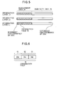
- FIG. 5 is a schematic drawing showing the data structure of the optical disc, including the information field in the management area.
- FIG. 6 is a conceptual drawing of the information field in the management area.
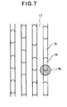
- FIG. 7 is a schematic drawing showing a focused spot and information written in tracks on information layer L2;
- FIG. 8 is a schematic drawing showing the focused spot and information written in tracks on information layer L3.
- FIG. 9 is a flowchart illustrating a sequence that reads information about the individual types of information layers.
- FIG. 10 is a flowchart illustrating a sequence that uses the information about the individual types of information layers to reproduce information from another information layer.
- the optical disc 1 in the first embodiment is provided with information layers L1, L2, and L3 for a plurality of differing optical disc standards.
- Information layers L1, L2, and L3 are disposed at distances of 0.1 mm, 0.6 mm, and 1.2 mm from the surface, in this order.
- These information layers L1, L2, and L3 satisfy the BD, DVD, and CD optical disc standards, in this order, information layer L1 being the layer with the highest recording density, information layer L3 being the layer with the lowest recording density.
- these layers are a reproduction-only layer, a writable layer, and a reproduction-only layer, respectively.
- a beam 3a emitted from a blue-violet semiconductor laser light source 2a which has a wavelength of about 405 nm, this being the shortest wavelength, is collimated by a collimator lens 4a, reflected by a prism 5a, and focused to a focused spot 7a on information layer L1 by an objective lens 6.
- the beam 3a reflected from information layer L1 returns to the objective lens 6, then passes through prisms 5a, 5b, 5c and is directed by a sensor lens 8 onto a photodetector 9.
- the photodetector 9 converts the received light beam into electrical signals for output to a signal processing means 10.
- the signal processing means 10 controls the amount of light emitted by light source 2a, generates a tracking error signal indicating the relative positional discrepancy between the focused spot and the tracks on the information layer, and after signal processing, outputs information to an image processing means 11.
- the image processing means 11 performs image processing and output.
- the above elements from the laser light source 2a to the image processing means 11 constitute an optical disc device 12.
- the optical disc device 12 records and reproduces information on the optical disc 1 according to commands from a host device 13.
- the host device 13 is a PC (personal computer) that instructs the optical disc device 12 to record and reproduce information.
- the host device 13 may be an audiovisual reproduction device that decodes information read out from the optical disc device 12 and outputs images and/or sounds, and/or an audiovisual recording device that encodes image and/or sound information input from an external device and instructs the optical disc device 12 to record the information.
- a beam 3b having a wavelength of about 650 nm is emitted from a red semiconductor laser light source 2b, collimated by a collimator lens 4a, reflected by prism 5b, and focused to a focused spot 7b on information layer L2 by the objective lens 6.
- the beam 3b now passes through information layer L1.
- the material and structure of information layer L1 are selected so as to avoid interference with access to information layer L2, taking physical properties such as transmittance and reflectance of a light beam having a wavelength of about 650 nm into consideration.
- the beam 3b reflected from information layer L2 returns to the objective lens 6, then passes through prisms 5a, 5b, 5c and is directed by the sensor lens 8 onto the photodetector 9.
- the signal processing means 10 and image processing means 11 operate as above; descriptions will be omitted.
- the signal processing means 10 controls light source 2b.
- a beam 3c emitted from an infrared semiconductor laser light source 2c having a wavelength of about 780 nm is collimated by a collimator lens 4c, reflected by a prism 5c, and focused to a focused spot 7c on information layer L3 by the objective lens 6.
- the beam 3c now passes through information layers L1 and L2.
- the materials and structure of information layers L1 and L2 are selected so as to avoid interference with access to information layer L3, taking physical properties such as transmittance and reflectance of a light beam having a wavelength of about 780 nm into consideration.
- the beam 3b reflected from information layer L2 returns to the objective lens 6, then passes through prisms 5a, 5b, 5c and is directed by the sensor lens 8 onto the photodetector 9.
- the signal processing means 10 and image processing means 11 operate as above; descriptions will be omitted. In FIG. 3 , the signal processing means 10 controls light source 2c.
- the management area 14 disposed in information layer L1 in FIG. 4 and FIG. 5 is located at the innermost circumference of the optical disc 1, the rest of the area being a user data area 15.
- the information field 16 in this management area 14 contains information indicating the type of each information layer.
- the optical disc device 12 obtains information indicating the types of information layers by reading the information from the information field 16.
- FIG. 6 is a conceptual drawing of the information field 16.
- Areas S1, S2, S3 in the information field 16 are bit areas indicating the types of information layers L1, L2, L3, respectively. Each of areas S1, S2, S3 comprises two bits, making six bits in total.
- the bit values are '01'
- the bit values are '10'. Absence of an information layer is represented by bit values of '00'. Therefore, in the first embodiment, areas S1, S2, S3 have values '01', '10', '01', respectively.
- FIG. 7 shows focused spot 7b and information written on a track of a writable information layer.
- a writable information layer has tracks referred to as lands 17 and grooves 18. Information is recorded as recording marks 19 by inducing a chemical change or shape change in the material.
- a tracking error signal is generated by the Differential Push-Pull method (DPP method), which is known in the art. In this method, the light is split into three beams and focused on the information layer, the reflected light is received by three binary photodetectors, and calculations are carried out to generate a tracking error signal.
- DPP method Differential Push-Pull method
- FIG. 8 shows focused spot 7c and information written on a track of a reproduction-only information layer.
- information is recorded in the form of microscopic holes called pits 20.
- the tracking error signal is generated by the Differential Phase Detection method (DPD method), which is also known in the art.
- DPD method Differential Phase Detection method
- the light beam is focused on an information layer, the reflected light of the focused light is received by one four-quadrant photodetector, and calculations are carried out to generate the tracking error signal.
- the optical disc device 12 when the optical disc 1 is inserted into the optical disc device 12 (ST1), the optical disc device 12 reads information from the information field 16 in the management area 14 on information layer L1 of the optical disc 1 to obtain information indicating the types of information layers L1, L2, L3. The information is retained in the signal processing means 10 (ST3) and the process ends (ST4). The device returns to a standby mode to wait for a command from the host device 13.
- the optical disc device 12 in response to a command from the host device 13 to reproduce information on information layer L2 (ST10), the optical disc device 12 follows the sequence by reading the type of information layer L2 retained in the signal processing means 10 as above (ST11).
- information layer L2 is not a reproduction-only layer (FALSE in ST12) but a writable layer (TRUE in ST13)
- the DPP method is selected, which is suitable for writable information layer L2, the laser power of the laser having a wavelength suitable for information layer L2 is set at the same time, a tracking error signal is generated (ST14), and information is reproduced from information layer L2 (ST15).
- the optical disc device 12 in response to a command from the host device 13 to reproduce information from information layer L3 (ST10), the optical disc device 12 follows the sequence by reading the type of information layer L3 retained in the signal processing means 10 as above (ST11).
- information layer L3 is a reproduction-only layer (TRUE in ST12)
- the DPD method is selected, which is suitable for reproduction-only information layer L3, the laser power of the laser having a wavelength suitable for information layer L3 is set at the same time, a tracking error signal is generated (ST16), and information is reproduced from information layer L3 (ST17).
- the optical disc device 12 When the optical disc device 12 receives the information reproducing command from the host device 13, if the type of information layer L3 retained in the signal processing means 10 is neither the reproduction-only type nor the writable type (FALSE in ST12 and ST13), that is, if the type information is not recognizable by the optical disc device, a notification is returned to the host device 13 indicating that the information layer to be reproduced is not accessible (ST18), and the process ends (ST19). The optical disc device 12 returns to a standby mode to wait for the next command from the host device 13.
- FALSE in ST12 and ST13 reproduction-only type nor the writable type
- steps ST12 and ST13 can be performed in either order to determine the type of the information layer, that is, to determine where the layer is of the reproduction-only type or writable type.
- FIG. 10 shows a case in which the host device 13 commands the reproduction of the information.
- access time can be similarly shortened and appropriate recording operations can be carried out on the information layer to be recorded, based on the information indicating the type of information layer.
- the information indicating the types of the other information layers is recorded in the management area of the information layer having the highest recording density. It can be anticipated that the information layer having the highest recording density will be accessed most frequently, so the optical disc device will be sure to read and retain the information.
- the optical disc device can set a suitable value for the laser power of the laser having a wavelength suitable for the layer to be accessed, based on the information indicating the type of the information layer. Also, the method of generating a tracking error indicating a relative positional discrepancy between the focused spot and the information written in tracks in a direction crossing the plurality of tracks can be determined in advance, so access time can be shortened.
- the second embodiment is similar to the first embodiment in regard to FIG. 1 to FIG. 5 and FIG. 7 to FIG. 10 , but differs from the first embodiment in regard to the usage of the part of the management area in FIG. 6 .
- the optical disc comprises a management area 14a located at its inner circumference and a user data area 15a extending toward its outer circumference.
- an indicator area 21 is provided inside the management area 14a to record information indicating the presence or absence of other information layers
- a type area 22 is provided to record information indicating the types of the other information layers.
- areas T2 and T3 of indicator area 21 respectively record information indicating the presence or absence of information layers L2 and L3 shown in FIG. 1 .
- Area T4 indicates the presence or absence of another information layer (not shown in optical disc 1) conforming to an optical disc standard other than the BD standard which uses a blue-violet semiconductor laser having about a 405-nm wavelength as a light source, or to a standard that may be developed in the future.
- Areas T2, T3, T4 store one bit of information each, so the indicator area 21 stores three bits in total.
- a bit value of '1' indicates the presence of another information layer, while a bit value of '0' indicates the absence of the other information layer.
- areas U2, U3, U4 in the type area 22 are associated with the information represented by areas T2, T3, T4 of indicator area 21, respectively; areas U2, U3, U4 record information indicating the type of the corresponding information layers. That is, when areas T2, T3, T4 indicate the presence of an information layer (bit value '1'), areas U2, U3, U4 indicate the type of the information layer. Areas U2, U3, U4 contain two bits of information each, so type area 22 has six bits in total. When a layer is of the reproduction-only type, the corresponding bit values are '00'. When the layer is of the writable type, the bit values are '01', and when it is of the rewritable type, the bit values are '10'.
- the writable type includes the DVD-R and DVD+R standards and their dual-layer standards, which permit writing but not rewriting.
- the rewritable type includes the dual-layer DVD-RW and DVD+RW standards and DVD-RAM.
- bit value '0' When one of areas T2, T3, T4 indicates the absence of a corresponding information layer (bit value '0'), the value '00', indicating a 'reserved area', is assigned to the corresponding U2, U3, or U4 area.
- this value is apparently the same as for an information layer of the reproduction-only type, no particular problem occurs, because when one of the T2, T3 and T4 bits is '0', the optical disc device will not read the corresponding U2, U3, or U4 area.
- a bit value for example '11'
- the device When an optical disc is inserted into the optical disc device, the device reads the information in areas T2, T3, T4 of the indicator area 21 in the management area 14a on information layer L1 of the optical disc to obtain information indicating the presence or absence of information layers L2 and L3 and information layers conforming to other standards.
- the optical disc device When one of areas T2, T3, T4 indicates the presence of a corresponding information layer (bit value '1'), the optical disc device reads the corresponding one of areas U2, U3, U4 in the type area 22 in the management area 14a, obtains information indicating the type of information layer, and retains the obtained information in the signal processing means 10. Subsequent operations are similar to those shown in the flowchart in FIG. 10 .
- the optical disc device can be configured to read only those of the areas U2, U3, U4 in the type area 22 corresponding to areas T2, T3, T4 indicating the presence of an information layer (bit value '1').
- the optical disc device can be configured to read information in all areas U2, U3, U4 of the type area 22 regardless of whether the corresponding information layer is present or not.
- the disc When an information layer corresponding to area T4 is present, and the information layer conforms to an optical disc standard, other than the BD standard, that uses a blue-violet semiconductor laser having a wavelength of about 405 nm as a light source, the disc will have a plurality of information layers (two layers, information layer L1 and the information layer corresponding to area T4) using the shortest wavelength of approximately 405 nm; in this case, the indicator area 21 and type area 22 are provided at least in information layer L1.
- the indicator area 21 and type area 22 may be provided not just on information layer L1 but also on the information layer corresponding to area T4.
- areas T4 and U4 may be left empty, with no particular information stored, reserved for use in case a new standard is developed in the future.
- the indicator area 21 and type area 22 then hold information for two types of information layers, these being information layers L2 and L3.
- the two bits assigned to area U2 may classify the corresponding DVD layer according to its type of information track structure.
- the classification may be based on the periodic structure of the information tracks, e.g., on their wobble frequency.
- the bit value may be '00'.
- the bit value may be '01'.
- DVD+R and DVD+RW which have wobble with higher wobble frequency than DVD-R and DVD-RW, the bit value may be '10'.
- the bit value may be '11'.
- the frequency structure of the information tracks in a DVD layer has the same format for each category, so the characteristics of the wobble signal detection circuit (a circuit such as a bandpass filter for detecting the frequency of the periodic structure) can be set prior to access to the DVD layer, the disc rotation can be rapidly brought to the target value, and the access time can therefore be shortened.
- a type area 22 which stores information indicating the types of information layers is provided in addition to the indicator area 21 which stores information indicating the presence or absence of other information layers, and the information in the indicator area 21 is related to the information in the type area 22 so that the information in the indicator area 21 and the information in the type area 22 have a hierarchical structure. Therefore, if another area is created in the user data area 15 in the future, or if another type of information layer is added, the hierarchical structure can be exploited to accommodate the expansion.
- the information is recorded in the management area in an information layer having the highest recording density, which is expected to be the information layer most frequently accessed, ensuring that the optical disc device will read and retain the information.
- the optical disc device can set a suitable value for the laser power of a laser having a wavelength suitable for the layer to be accessed, based on information such as the above.
- the method of generating the tracking error signal indicating a relative positional discrepancy between the focused spot and the information written in the tracks in a direction crossing a plurality of tracks can be determined in advance, so the access time can be shortened.
- the optical disc 1 has at most two types of information layers, including the type of the L1 layer.
- the third embodiment is similar to the second embodiment in regard to FIG. 1 to FIG. 5 and FIG. 7 to FIG. 10 , but differs from the second embodiment in regard to the usage of the indicator area 21 and type area 22 in FIG. 12 .
- the areas T2, T3, T4 in the indicator area 21 are the same as in FIG. 12 .
- area V1 in the type area 22 indicates the type of this information layer.
- the type area 22 includes only the two bits of information in area V1. The values of these bits are '00' when the information layer is of the reproduction-only type, '01' when it is of the writable type, and '10' when it is of the rewritable type.
- the writable type includes DVD-R, DVD+R, and their dual-layer standards.
- the rewritable type includes dual-layer DVD-RW and DVD+RW and DVD-RAM.
- information layer L1 is a writable layer or pair of layers
- the type area 22 can have only two bits, producing a saving of information bits as compared with the second embodiment above.
- there is an anticipated market demand for optical discs having only one of information layers L2 and L3 and using it as a reproduction-only layer so if only optical discs having information layer L2 or L3 and using it as a reproduction-only layer are manufactured and sold, the two bits of area V1 will suffice for the type area 22.
- the classification in area V1 may be based on the type of information track structure, such as the presence or absence of wobble.
- the area V1 of the type area 22 was shown as having two bits of information in this embodiment, it may have only one bit of information, saving one further information bit.
- the reproduction-only type may be indicated by '0' and other types, that is, the writable type and rewritable type, may be indicated by '1'.
- the classification may be based on the type of information track structure: for example, '0' when there is no wobble and '1' when wobble is present.
- the one bit of area V1 can be reassigned to area T4, since area T4 is a one-bit area to begin with.
- This scheme saves a still further information bit and, by placing the indicator area 21 and type area 22 adjacent to each other, can further shorten the access time of the disc device.
- the type area 22 of the second and third embodiments is a reserved area having a value of '00' or '0' with no information assigned, in expectation that effective use of this area can be made in the future. Also, as described in the third embodiment, if only optical discs having information layers L2 and L3 of the reproduction-only type are manufactured and sold, there is no particular need to assign information indicating the type of the information layer to the type area 22.
- bit or bits in the type area 22 to indicate the type of information layer.
- the bit values '00' or '0' should be assigned to indicate the reproduction-only type, which is the type most frequently used. If these bits are used for indicating some completely different property, the value '00' or '0' should be protected in some way, such as being used only as a reserved value.
- This embodiment provides only the information stored in the indicator area to indicate the presence or absence of other information layers, but since this information enables the optical disc device to identify the presence or absence of other information layers, it contributes to the shortening of the access time.
- a multilayer optical disc having information layers conforming to a plurality of different optical disc standards, wherein an information layer of highest recording density has a management area in which information indicating the types of other information layers is recorded, the types including at least a reproduction-only type.
- Said optical disc may further include a writable type.
- a multilayer optical disc having information layers conforming to a plurality of different optical disc standards, wherein an information layer of highest recording density has a management area in which information indicating presence or absence of other information layers is recorded.
- optical disc information indicating the types of the other information layers may also be recorded in the management area.
- the information indicating the presence or absence of the other information layers may be associated with the information indicating the types of the other information layers.
- a zero bit may be assigned to the information indicating the type of the other information layer.
- the information indicating the types of the other information layers may be based on the type of structure of the information tracks in the other information layers.
- the type of structure of the information tracks may be a periodic structure.
- the other information layers may include at least two types of information layers adapted for a single wavelength each.
- the information layers may include a plurality of information layers adapted for a shortest wavelength.
- the information indicating the types of the other information layers may indicate only one type.
- '00' or '0' may be assigned to indicate the read-only type.
- an optical disc device for reading information from the optical discs previously mentioned comprising:
- an optical disc device for writing to a multilayer optical disc having information layers conforming to a plurality of different optical disc standards, comprising means for recording information indicating the types of other information layers in a management area of an information layer of highest recording density, the types including at least a reproduction-only type.
- an optical disc device for recording or reproducing information written in tracks on the optical discs previously mentioned by a focused spot, comprising:
- an optical disc device for reading information from the optical disc previously mentioned comprising:
- an optical disc device for reading information from the optical discs previously mentioned, comprising:
- the optical disc device previously mentioned may further comprise means for setting laser power for reproduction of information in an information layer to be accessed, based on the extracted information.
- an optical disc device for reading information from the optical discs previously mentioned comprising:
- an optical disc device for writing to a multilayer optical disc having information layers conforming to a plurality of different optical disc standards, comprising means for recording information indicating presence or absence of other information layers in a management area in an information layer of highest recording density.
- the optical disc device previously mentioned may further comprise means for recording information indicating the types of the other information layers in the management area.
Abstract
Description
- The present invention relates to a multilayer optical disc having information layers conforming to a plurality of different optical disc standards and an optical disc device for recording or reproducing information on the optical disc.
- Optical discs are a subject of research in the information recording field. They have a wide range of applications, from industrial use to consumer use, because they enable non-contact recording and reproduction, because they can accommodate large files at low cost, and because reproduction-only, writable, or rewritable media can be selected according to the application.
- The capacity of optical discs has been increased by reducing the size of the information stored on the tracks, by using laser beams having shorter wavelengths as light sources for recording and reproducing, by using objective lenses with higher numerical apertures, and by reducing the size of the focused light spot on the focal plane.
- For example, in a CD (compact disc), the thickness of the disc substrate used as a light transmitting layer is about 1.2 mm, the wavelength of the laser beam is about 780 nm, the numerical aperture (NA) of the objective lens is 0.45, and the disc capacity is 650 MB. In a DVD (digital versatile disc), the thickness of the disc substrate used as a light transmitting layer is about 0.6 mm, the wavelength of the laser beam is about 650 nm, the numerical aperture of the object lens is 0.6, and the disc capacity is 4.7 GB. For a DVD, two disc substrates having thicknesses of about 0.6 mm each are laminated together, to obtain a disc having a thickness of about 1.2 mm.
- A BD (Blu-ray disc) disc having a still higher density uses an optical disc having a protection layer as thin as 0.1 mm as the light transmitting layer on the optical recording layer. With a laser beam wavelength of about 405 nm and a numerical aperture of 0.85, capacities in excess of 23 GB are obtained.
- Thus, as optical disc capacities have increased, various optical disc standards have been established, including CD, DVD, and BD. Optical disc recording and reproducing devices are generally compatible with a plurality of different optical disc standards.
- For example, some DVD recording and reproducing devices can record and reproduce information not only on a DVD but also on a CD. Some BD recording and reproducing devices can record and reproduce information on BDs, DVDs, and CDs. These compatible recording and reproducing devices are extremely convenient because they allow the user to record and reproduce information on optical discs in the user's possession that conform to old standards, and they have played an important role in smoothing the introduction of new standards.
- Although discs have been manufactured according to each of the different standards, to increase the user's convenience, a multilayer optical disc having information layers conforming to a plurality of different optical disc standards has been developed (for example, patent document 1).
- Patent document 1: Japanese Unexamined Patent Application Publication No.
2004-95005 - A problem with such optical discs as the above is that when one information layer is being accessed, it is not known whether another information layer is present or not, so if the need to reproduce or record information on another information layer suddenly arises, it takes time to access the other designated information layer.
- Another problem with optical discs such as the above is that the type of one information layer is not recorded on another layer, so when an optical disc device conforming to a plurality of different optical disc standards reads or writes information, every time the device accesses a different information layer, it must read the type of the layer to select a method of generating a tracking error signal adapted to the type; consequently, access takes time.
- The purpose of the present invention is to shorten the access time in a multilayer optical disc having information layers conforming to a plurality of different optical disc standards.
- In a multilayer optical disc having information layers conforming to a plurality of different optical disc standards, the present invention is an optical disc in which an information layer of highest recording density has a management area in which information indicating the types of other information layers is recorded, the types including at least a reproduction-only type.
- In a multilayer optical disc having information layers conforming to a plurality of different optical disc standards, the present invention is also an optical disc in which an information layer of highest recording density has a management area in which information indicating presence or absence of other information layers is recorded.
- In a multilayer optical disc having information layers conforming to a plurality of different optical disc standards, the present invention enables the access time to be shortened.
-
-
FIG. 1 is a schematic drawing of an optical disc and optical disc device in a first embodiment, showing the optical disc device accessing information layer L1 of the optical disc. -
FIG. 2 is a schematic drawing of the optical disc and optical disc device in the first embodiment, showing the optical disc device accessing information layer L2 of the optical disc. -
FIG. 3 is a schematic drawing of the optical disc and optical disc device in the first embodiment, showing the optical disc device accessing information layer L3 of the optical disc. -
FIG. 4 is a schematic drawing showing the management area in information layer L1 of the optical disc in the first embodiment. -
FIG. 5 is a schematic drawing of the data structure of the optical disc in the first embodiment, showing an information field in the management area. -
FIG. 6 is a conceptual drawing of the information field in the management area in the first embodiment. -
FIG. 7 is a schematic drawing showing a focused spot and information written in tracks on information layer L2 in the first embodiment. -
FIG. 8 is a schematic drawing showing a focused spot and information written in tracks on information layer L3 in the first embodiment. -
FIG. 9 is a flowchart illustrating a sequence that reads information about the individual types of information layers in the first embodiment. -
FIG. 10 is a flowchart illustrating a sequence that uses the information about the individual types of information layers in the first embodiment to reproduce information from another information layer. -
FIG. 11 is a schematic diagram showing the management area in information layer L2 in a second embodiment. -
FIG. 12 is a conceptual drawing of parts of the management area in the second embodiment. -
FIG. 13 is a schematic diagram showing parts of a management area in a third embodiment. - Explanation of
Reference Characters 1 optical disc, 2a blue-violet semiconductor laser light source, 2b red semiconductor laser light source, 2c infrared semiconductor laser light source, 3a beam from blue-violet semiconductor laser light source, 3b beam from red semiconductor laser light source, 3c beam from infrared semiconductor laser light source, 4a, 4b, 4c collimating lens, 5a, 5b, 5c prism, 6 objective lens, 7a focused spot from blue-violet semiconductor laser light source, 7b focused spot from red semiconductor laser light source, 7c focused spot from infrared semiconductor laser light source, 8 sensor lens, 9 photodetector, 10 signal processing means, 11 image processing means, 12 optical disc device, 13 host device, 14, 14a management area, 15, 15a user data area, 16, information field, 17 land, 18 groove, 19 recording mark, 20 pit, 21 indicator area, 22 type area -
FIGs. 1 to 3 are schematic drawings showing an optical disc and an optical disc device accessing an information layer in the optical disc in the first embodiment of the invention;FIG. 4 is a schematic drawing showing the management area in information layer L1 of the optical disc inFIG. 1 .FIG. 5 is a schematic drawing showing the data structure of the optical disc, including the information field in the management area.FIG. 6 is a conceptual drawing of the information field in the management area.FIG. 7 is a schematic drawing showing a focused spot and information written in tracks on information layer L2;FIG. 8 is a schematic drawing showing the focused spot and information written in tracks on information layer L3.FIG. 9 is a flowchart illustrating a sequence that reads information about the individual types of information layers.FIG. 10 is a flowchart illustrating a sequence that uses the information about the individual types of information layers to reproduce information from another information layer. - The first embodiment of the invention will now be described with reference to the attached drawings. The
optical disc 1 in the first embodiment is provided with information layers L1, L2, and L3 for a plurality of differing optical disc standards. Information layers L1, L2, and L3 are disposed at distances of 0.1 mm, 0.6 mm, and 1.2 mm from the surface, in this order. These information layers L1, L2, and L3 satisfy the BD, DVD, and CD optical disc standards, in this order, information layer L1 being the layer with the highest recording density, information layer L3 being the layer with the lowest recording density. In the following description, these layers are a reproduction-only layer, a writable layer, and a reproduction-only layer, respectively. - In the state in
FIG. 1 , information layer L1 is being accessed; abeam 3a emitted from a blue-violet semiconductorlaser light source 2a, which has a wavelength of about 405 nm, this being the shortest wavelength, is collimated by acollimator lens 4a, reflected by aprism 5a, and focused to a focusedspot 7a on information layer L1 by anobjective lens 6. - The
beam 3a reflected from information layer L1 returns to theobjective lens 6, then passes throughprisms sensor lens 8 onto aphotodetector 9. - The
photodetector 9 converts the received light beam into electrical signals for output to a signal processing means 10. The signal processing means 10 controls the amount of light emitted bylight source 2a, generates a tracking error signal indicating the relative positional discrepancy between the focused spot and the tracks on the information layer, and after signal processing, outputs information to an image processing means 11. The image processing means 11 performs image processing and output. - The above elements from the
laser light source 2a to the image processing means 11 constitute anoptical disc device 12. Theoptical disc device 12 records and reproduces information on theoptical disc 1 according to commands from ahost device 13. Thehost device 13 is a PC (personal computer) that instructs theoptical disc device 12 to record and reproduce information. Alternatively, thehost device 13 may be an audiovisual reproduction device that decodes information read out from theoptical disc device 12 and outputs images and/or sounds, and/or an audiovisual recording device that encodes image and/or sound information input from an external device and instructs theoptical disc device 12 to record the information. - In the state in
FIG. 2 , information layer L2 is being accessed. Abeam 3b having a wavelength of about 650 nm is emitted from a red semiconductorlaser light source 2b, collimated by acollimator lens 4a, reflected byprism 5b, and focused to a focusedspot 7b on information layer L2 by theobjective lens 6. - The
beam 3b now passes through information layer L1. - The material and structure of information layer L1 are selected so as to avoid interference with access to information layer L2, taking physical properties such as transmittance and reflectance of a light beam having a wavelength of about 650 nm into consideration.
- The
beam 3b reflected from information layer L2 returns to theobjective lens 6, then passes throughprisms sensor lens 8 onto thephotodetector 9. The signal processing means 10 and image processing means 11 operate as above; descriptions will be omitted. InFIG. 2 , the signal processing means 10 controlslight source 2b. - In the state in
FIG. 3 , information layer L3 is being accessed. Abeam 3c emitted from an infrared semiconductorlaser light source 2c having a wavelength of about 780 nm is collimated by acollimator lens 4c, reflected by aprism 5c, and focused to afocused spot 7c on information layer L3 by theobjective lens 6. - The
beam 3c now passes through information layers L1 and L2. The materials and structure of information layers L1 and L2 are selected so as to avoid interference with access to information layer L3, taking physical properties such as transmittance and reflectance of a light beam having a wavelength of about 780 nm into consideration. - The
beam 3b reflected from information layer L2 returns to theobjective lens 6, then passes throughprisms sensor lens 8 onto thephotodetector 9. The signal processing means 10 and image processing means 11 operate as above; descriptions will be omitted. InFIG. 3 , the signal processing means 10 controlslight source 2c. - The
management area 14 disposed in information layer L1 inFIG. 4 andFIG. 5 is located at the innermost circumference of theoptical disc 1, the rest of the area being a user data area 15. Theinformation field 16 in thismanagement area 14 contains information indicating the type of each information layer. Theoptical disc device 12 obtains information indicating the types of information layers by reading the information from theinformation field 16. -
FIG. 6 is a conceptual drawing of theinformation field 16. Areas S1, S2, S3 in theinformation field 16 are bit areas indicating the types of information layers L1, L2, L3, respectively. Each of areas S1, S2, S3 comprises two bits, making six bits in total. When an information layer is of the reproduction-only type, the bit values are '01', and when a layer is of the writable type, the bit values are '10'. Absence of an information layer is represented by bit values of '00'. Therefore, in the first embodiment, areas S1, S2, S3 have values '01', '10', '01', respectively. -
FIG. 7 shows focusedspot 7b and information written on a track of a writable information layer. A writable information layer has tracks referred to aslands 17 andgrooves 18. Information is recorded as recording marks 19 by inducing a chemical change or shape change in the material. In a writable information layer, a tracking error signal is generated by the Differential Push-Pull method (DPP method), which is known in the art. In this method, the light is split into three beams and focused on the information layer, the reflected light is received by three binary photodetectors, and calculations are carried out to generate a tracking error signal. -
FIG. 8 shows focusedspot 7c and information written on a track of a reproduction-only information layer. On a reproduction-only layer, information is recorded in the form of microscopic holes called pits 20. The tracking error signal is generated by the Differential Phase Detection method (DPD method), which is also known in the art. In this method, the light beam is focused on an information layer, the reflected light of the focused light is received by one four-quadrant photodetector, and calculations are carried out to generate the tracking error signal. - In
FIG. 9 , when theoptical disc 1 is inserted into the optical disc device 12 (ST1), theoptical disc device 12 reads information from theinformation field 16 in themanagement area 14 on information layer L1 of theoptical disc 1 to obtain information indicating the types of information layers L1, L2, L3. The information is retained in the signal processing means 10 (ST3) and the process ends (ST4). The device returns to a standby mode to wait for a command from thehost device 13. - In
FIG. 10 , in response to a command from thehost device 13 to reproduce information on information layer L2 (ST10), theoptical disc device 12 follows the sequence by reading the type of information layer L2 retained in the signal processing means 10 as above (ST11). As information layer L2 is not a reproduction-only layer (FALSE in ST12) but a writable layer (TRUE in ST13), the DPP method is selected, which is suitable for writable information layer L2, the laser power of the laser having a wavelength suitable for information layer L2 is set at the same time, a tracking error signal is generated (ST14), and information is reproduced from information layer L2 (ST15). - Similarly, in response to a command from the
host device 13 to reproduce information from information layer L3 (ST10), theoptical disc device 12 follows the sequence by reading the type of information layer L3 retained in the signal processing means 10 as above (ST11). As information layer L3 is a reproduction-only layer (TRUE in ST12), the DPD method is selected, which is suitable for reproduction-only information layer L3, the laser power of the laser having a wavelength suitable for information layer L3 is set at the same time, a tracking error signal is generated (ST16), and information is reproduced from information layer L3 (ST17). - When the
optical disc device 12 receives the information reproducing command from thehost device 13, if the type of information layer L3 retained in the signal processing means 10 is neither the reproduction-only type nor the writable type (FALSE in ST12 and ST13), that is, if the type information is not recognizable by the optical disc device, a notification is returned to thehost device 13 indicating that the information layer to be reproduced is not accessible (ST18), and the process ends (ST19). Theoptical disc device 12 returns to a standby mode to wait for the next command from thehost device 13. - In
FIG. 10 , steps ST12 and ST13 can be performed in either order to determine the type of the information layer, that is, to determine where the layer is of the reproduction-only type or writable type. -
FIG. 10 shows a case in which thehost device 13 commands the reproduction of the information. When thehost device 13 commands the recording of the information, access time can be similarly shortened and appropriate recording operations can be carried out on the information layer to be recorded, based on the information indicating the type of information layer. - In this embodiment, in a multilayer optical disc having information layers conforming to a plurality of different optical disc standards, information indicating the type of other information layers is recorded, so the optical disc device can easily identify the types of the other information layers, and access time to those layers can be shortened.
- Furthermore, the information indicating the types of the other information layers is recorded in the management area of the information layer having the highest recording density. It can be anticipated that the information layer having the highest recording density will be accessed most frequently, so the optical disc device will be sure to read and retain the information.
- When recording and reproducing information on an optical disc as above, before access, the optical disc device can set a suitable value for the laser power of the laser having a wavelength suitable for the layer to be accessed, based on the information indicating the type of the information layer. Also, the method of generating a tracking error indicating a relative positional discrepancy between the focused spot and the information written in tracks in a direction crossing the plurality of tracks can be determined in advance, so access time can be shortened.
- The second embodiment is similar to the first embodiment in regard to
FIG. 1 to FIG. 5 andFIG. 7 to FIG. 10 , but differs from the first embodiment in regard to the usage of the part of the management area inFIG. 6 . - Referring to
FIG. 11 , the optical disc comprises a management area 14a located at its inner circumference and a user data area 15a extending toward its outer circumference. Inside the management area 14a, anindicator area 21 is provided to record information indicating the presence or absence of other information layers, and atype area 22 is provided to record information indicating the types of the other information layers. InFIG. 12 , areas T2 and T3 ofindicator area 21 respectively record information indicating the presence or absence of information layers L2 and L3 shown inFIG. 1 . Area T4 indicates the presence or absence of another information layer (not shown in optical disc 1) conforming to an optical disc standard other than the BD standard which uses a blue-violet semiconductor laser having about a 405-nm wavelength as a light source, or to a standard that may be developed in the future. Areas T2, T3, T4 store one bit of information each, so theindicator area 21 stores three bits in total. A bit value of '1' indicates the presence of another information layer, while a bit value of '0' indicates the absence of the other information layer. - In
FIG. 12 , areas U2, U3, U4 in thetype area 22 are associated with the information represented by areas T2, T3, T4 ofindicator area 21, respectively; areas U2, U3, U4 record information indicating the type of the corresponding information layers. That is, when areas T2, T3, T4 indicate the presence of an information layer (bit value '1'), areas U2, U3, U4 indicate the type of the information layer. Areas U2, U3, U4 contain two bits of information each, sotype area 22 has six bits in total. When a layer is of the reproduction-only type, the corresponding bit values are '00'. When the layer is of the writable type, the bit values are '01', and when it is of the rewritable type, the bit values are '10'. The writable type includes the DVD-R and DVD+R standards and their dual-layer standards, which permit writing but not rewriting. The rewritable type includes the dual-layer DVD-RW and DVD+RW standards and DVD-RAM. When one of areas T2, T3, T4 indicates the absence of a corresponding information layer (bit value '0'), the value '00', indicating a 'reserved area', is assigned to the corresponding U2, U3, or U4 area. Although, this value is apparently the same as for an information layer of the reproduction-only type, no particular problem occurs, because when one of the T2, T3 and T4 bits is '0', the optical disc device will not read the corresponding U2, U3, or U4 area. Alternatively, a bit value (for example '11') other than the above can be assigned. - When an optical disc is inserted into the optical disc device, the device reads the information in areas T2, T3, T4 of the
indicator area 21 in the management area 14a on information layer L1 of the optical disc to obtain information indicating the presence or absence of information layers L2 and L3 and information layers conforming to other standards. When one of areas T2, T3, T4 indicates the presence of a corresponding information layer (bit value '1'), the optical disc device reads the corresponding one of areas U2, U3, U4 in thetype area 22 in the management area 14a, obtains information indicating the type of information layer, and retains the obtained information in the signal processing means 10. Subsequent operations are similar to those shown in the flowchart inFIG. 10 . - The optical disc device can be configured to read only those of the areas U2, U3, U4 in the
type area 22 corresponding to areas T2, T3, T4 indicating the presence of an information layer (bit value '1'). Alternatively, the optical disc device can be configured to read information in all areas U2, U3, U4 of thetype area 22 regardless of whether the corresponding information layer is present or not. - When an information layer corresponding to area T4 is present, and the information layer conforms to an optical disc standard, other than the BD standard, that uses a blue-violet semiconductor laser having a wavelength of about 405 nm as a light source, the disc will have a plurality of information layers (two layers, information layer L1 and the information layer corresponding to area T4) using the shortest wavelength of approximately 405 nm; in this case, the
indicator area 21 andtype area 22 are provided at least in information layer L1. Theindicator area 21 andtype area 22 may be provided not just on information layer L1 but also on the information layer corresponding to area T4. - Alternatively, areas T4 and U4 may be left empty, with no particular information stored, reserved for use in case a new standard is developed in the future. The
indicator area 21 andtype area 22 then hold information for two types of information layers, these being information layers L2 and L3. - Alternatively, the two bits assigned to area U2 may classify the corresponding DVD layer according to its type of information track structure. The classification may be based on the periodic structure of the information tracks, e.g., on their wobble frequency. For example, when the layer is a reproduction-only type layer such as a DVD-ROM layer having only pre-pits with no wobble, the bit value may be '00'. For DVD-R and DVD-RW, which have wobble, the bit value may be '01'. For DVD+R and DVD+RW, which have wobble with higher wobble frequency than DVD-R and DVD-RW, the bit value may be '10'. For DVD-RAM in which the head is shifted in the radius direction on a land/groove single spiral structure with no wobble, the bit value may be '11'. The frequency structure of the information tracks in a DVD layer has the same format for each category, so the characteristics of the wobble signal detection circuit (a circuit such as a bandpass filter for detecting the frequency of the periodic structure) can be set prior to access to the DVD layer, the disc rotation can be rapidly brought to the target value, and the access time can therefore be shortened.
- In this embodiment, in a multilayer optical disc having information layers conforming to a plurality of different optical disc standards, information indicating the presence of other information layers is recorded, so the optical disc device can easily identify the presence or absence of other information layers, and access time can be shortened.
- Furthermore, in the management region of the optical disc, a
type area 22 which stores information indicating the types of information layers is provided in addition to theindicator area 21 which stores information indicating the presence or absence of other information layers, and the information in theindicator area 21 is related to the information in thetype area 22 so that the information in theindicator area 21 and the information in thetype area 22 have a hierarchical structure. Therefore, if another area is created in the user data area 15 in the future, or if another type of information layer is added, the hierarchical structure can be exploited to accommodate the expansion. - Furthermore, the information is recorded in the management area in an information layer having the highest recording density, which is expected to be the information layer most frequently accessed, ensuring that the optical disc device will read and retain the information.
- When recording and reproducing information on an optical disc of this type, the optical disc device can set a suitable value for the laser power of a laser having a wavelength suitable for the layer to be accessed, based on information such as the above. The method of generating the tracking error signal indicating a relative positional discrepancy between the focused spot and the information written in the tracks in a direction crossing a plurality of tracks can be determined in advance, so the access time can be shortened.
- In the third embodiment, the
optical disc 1 has at most two types of information layers, including the type of the L1 layer. The third embodiment is similar to the second embodiment in regard toFIG. 1 to FIG. 5 andFIG. 7 to FIG. 10 , but differs from the second embodiment in regard to the usage of theindicator area 21 andtype area 22 inFIG. 12 . - In
FIG. 13 , the areas T2, T3, T4 in theindicator area 21 are the same as inFIG. 12 . - When an information layer other than information layer L1 is present, area V1 in the
type area 22 indicates the type of this information layer. Thetype area 22 includes only the two bits of information in area V1. The values of these bits are '00' when the information layer is of the reproduction-only type, '01' when it is of the writable type, and '10' when it is of the rewritable type. The writable type includes DVD-R, DVD+R, and their dual-layer standards. The rewritable type includes dual-layer DVD-RW and DVD+RW and DVD-RAM. - For example when information layer L1 is a writable layer or pair of layers, information layers L2 and L3 are reproduction-only layers, and no other layers are present (T2 = 1, T3 = 1, T4 = 0), the bit values in area V1 will be '00'.
- Thus, in the
optical disc 1, when at least one of areas T2, T3, T4 in theindicator area 21 has a bit value of '1' and the corresponding information layers are of only one type, or when only one of areas T2, T3, T4 has a bit value of '1', thetype area 22 can have only two bits, producing a saving of information bits as compared with the second embodiment above. In particular, there is an anticipated market demand for optical discs having only one of information layers L2 and L3 and using it as a reproduction-only layer, so if only optical discs having information layer L2 or L3 and using it as a reproduction-only layer are manufactured and sold, the two bits of area V1 will suffice for thetype area 22. - Alternatively, as shown in the second embodiment, the classification in area V1 may be based on the type of information track structure, such as the presence or absence of wobble.
- Although the area V1 of the
type area 22 was shown as having two bits of information in this embodiment, it may have only one bit of information, saving one further information bit. In this case, the reproduction-only type may be indicated by '0' and other types, that is, the writable type and rewritable type, may be indicated by '1'. - Alternatively, the classification may be based on the type of information track structure: for example, '0' when there is no wobble and '1' when wobble is present.
- Furthermore, when the area V1 storing information indicating the type of information layer has only one bit and area T4 in the
indicator area 21 inFIG. 13 is a reserved area with no particular information, the one bit of area V1 can be reassigned to area T4, since area T4 is a one-bit area to begin with. This scheme saves a still further information bit and, by placing theindicator area 21 andtype area 22 adjacent to each other, can further shorten the access time of the disc device. - Other effects are similar to those shown in first and second embodiments.
- It is possible to use the
type area 22 of the second and third embodiments as a reserved area having a value of '00' or '0' with no information assigned, in expectation that effective use of this area can be made in the future. Also, as described in the third embodiment, if only optical discs having information layers L2 and L3 of the reproduction-only type are manufactured and sold, there is no particular need to assign information indicating the type of the information layer to thetype area 22. - However, if the market changes in the future and not only optical discs having information layers L2 and L3 of the reproduction-only type but various other types of hybrid optical discs are manufactured and sold, it will be necessary to use the bit or bits in the
type area 22 to indicate the type of information layer. In order to ensure compatibility with optical discs having information layers L2 and L3 of the reproduction-only type, the bit values '00' or '0' should be assigned to indicate the reproduction-only type, which is the type most frequently used. If these bits are used for indicating some completely different property, the value '00' or '0' should be protected in some way, such as being used only as a reserved value. - This embodiment provides only the information stored in the indicator area to indicate the presence or absence of other information layers, but since this information enables the optical disc device to identify the presence or absence of other information layers, it contributes to the shortening of the access time.
- In a further aspect of the present invention a multilayer optical disc is provided having information layers conforming to a plurality of different optical disc standards, wherein an information layer of highest recording density has a management area in which information indicating the types of other information layers is recorded, the types including at least a reproduction-only type.
- Said optical disc may further include a writable type.
- In a further aspect of the present invention a multilayer optical disc is provided having information layers conforming to a plurality of different optical disc standards, wherein an information layer of highest recording density has a management area in which information indicating presence or absence of other information layers is recorded.
- In said optical disc information indicating the types of the other information layers may also be recorded in the management area.
- In said optical discs previously mentioned the information indicating the presence or absence of the other information layers may be associated with the information indicating the types of the other information layers.
- In said optical discs previously mentioned if the information indicating the presence or absence of another information layer indicates absence, a zero bit may be assigned to the information indicating the type of the other information layer.
- In said optical discs previously mentioned the information indicating the types of the other information layers may be based on the type of structure of the information tracks in the other information layers.
- In said optical disc the type of structure of the information tracks may be a periodic structure.
- In said optical discs previously mentioned the other information layers may include at least two types of information layers adapted for a single wavelength each.
- In said optical discs previously mentioned the information layers may include a plurality of information layers adapted for a shortest wavelength.
- In said optical discs previously mentioned the information indicating the types of the other information layers may indicate only one type.
- In said optical discs previously mentioned in the information indicating the types of other information layers, '00' or '0' may be assigned to indicate the read-only type.
- In a further aspect of the invention an optical disc device is provided for reading information from the optical discs previously mentioned comprising:
- means for accessing the information layer of the highest recording density;
- means for reading information in the management area of the accessed information layer; and
- means for extracting information indicating the types of the other information layers from the information in the management area.
- In a further aspect of the invention an optical disc device is provided for writing to a multilayer optical disc having information layers conforming to a plurality of different optical disc standards, comprising
means for recording information indicating the types of other information layers in a management area of an information layer of highest recording density, the types including at least a reproduction-only type. - In a further aspect of the invention an optical disc device is provided for recording or reproducing information written in tracks on the optical discs previously mentioned by a focused spot, comprising:
- means for extracting information indicating the types of other information layers;
- means for retaining the extracted information indicating the types; and
- means for generating a tracking error indicating a relative positional discrepancy between the focused spot and the information written in tracks in a direction crossing the plurality of tracks, according to the retained information, when accessing each information layer.
- In a further aspect of the invention an optical disc device is provided for reading information from the optical disc previously mentioned comprising:
- means for accessing the information layer of the highest recording density;
- means for reading information from the management area in the accessed information layer; and
- means for extracting the information indicating the presence or absence of other information layers from the information in the management area.
- In a further aspect of the invention an optical disc device is provided for reading information from the optical discs previously mentioned, comprising:
- means for accessing the information layer of the highest recording density;
- means for reading information from the management area in the accessed information layer; and
- means for extracting the information indicating the presence or absence of the other information layers and information indicating the types of the other information layers from the information in the management area.
- The optical disc device previously mentioned may further comprise means for setting laser power for reproduction of information in an information layer to be accessed, based on the extracted information.
- In a further aspect of the invention an optical disc device is provided for reading information from the optical discs previously mentioned comprising:
- means for accessing the information layer with the highest recording density;
- means for reading information from the management area in the accessed information layer;
- means for extracting the information indicating the presence or absence of the other information layers and information indicating the types of the other information layers from the information in the management area; and
- means for setting characteristics of a circuit for detecting a frequency of the periodic structure of the information tracks according to the extracted information.
- In a further aspect of the present invention an optical disc device is provided for writing to a multilayer optical disc having information layers conforming to a plurality of different optical disc standards, comprising
means for recording information indicating presence or absence of other information layers in a management area in an information layer of highest recording density. - The optical disc device previously mentioned may further comprise means for recording information indicating the types of the other information layers in the management area.
Claims (3)
- An optical disc (1) comprising:a management area (14) provided on an information layer (L1) satisfying BD optical disc standard, said management area (14) storing information (T2, T3) regarding a plurality of other information layers (L2, L3) of different optical disc standards using different laser wavelengths;said information (T2, T3) representing if each of said other information layers (L2, L3) of different optical disc standards is present in said optical disc (1);wherein said management area (14) is provided on an information layer (L1) of which recording density is higher than recording density of any of said other information layers (L2, L3).
- An optical disc drive for reading an optical disc (1) according to claim 1 comprising:means for accessing said management area (14),means for extracting said information (T2, T3) representing if each of said other information layers (L2, L3) is present in said optical disc (1), andmeans for reading said optical disc (1).
- An optical disc drive for reading an optical disc (1) and recording on an optical disc (1) according to claim 1 comprising:means for accessing said management area (14),means for extracting said information (T2, T3) representing if each of said other information layers (L2, L3) is present in said optical disc (1),means for reading said optical disc (1), andmeans for recording on said optical disc (1).
Applications Claiming Priority (3)
| Application Number | Priority Date | Filing Date | Title |
|---|---|---|---|
| JP2005039026 | 2005-02-16 | ||
| JP2005043131A JP3812584B1 (en) | 2005-02-16 | 2005-02-18 | Optical disc and optical disc apparatus |
| EP05772619.2A EP1850341B8 (en) | 2005-02-16 | 2005-08-19 | Optical disc and optical disc device |
Related Parent Applications (2)
| Application Number | Title | Priority Date | Filing Date |
|---|---|---|---|
| EP05772619.2A Division-Into EP1850341B8 (en) | 2005-02-16 | 2005-08-19 | Optical disc and optical disc device |
| EP05772619.2 Division | 2005-08-19 |
Publications (3)
| Publication Number | Publication Date |
|---|---|
| EP2521127A2 true EP2521127A2 (en) | 2012-11-07 |
| EP2521127A3 EP2521127A3 (en) | 2013-03-20 |
| EP2521127B1 EP2521127B1 (en) | 2013-11-20 |
Family
ID=36916250
Family Applications (15)
| Application Number | Title | Priority Date | Filing Date |
|---|---|---|---|
| EP12178416.9A Active EP2521134B1 (en) | 2005-02-16 | 2005-08-19 | Optical disc and optical disc device |
| EP05772619.2A Active EP1850341B8 (en) | 2005-02-16 | 2005-08-19 | Optical disc and optical disc device |
| EP10007570A Active EP2249346B1 (en) | 2005-02-16 | 2005-08-19 | Optical disc and optical disc device |
| EP12178407.8A Active EP2521127B1 (en) | 2005-02-16 | 2005-08-19 | Optical disc and optical disc device |
| EP12178412.8A Active EP2521132B1 (en) | 2005-02-16 | 2005-08-19 | Optical disc and optical disc device |
| EP14150632.9A Active EP2720228B1 (en) | 2005-02-16 | 2005-08-19 | Optical disc and optical disc device |
| EP12178408.6A Active EP2521128B1 (en) | 2005-02-16 | 2005-08-19 | Optical disc and optical disc device |
| EP12178411.0A Active EP2521131B1 (en) | 2005-02-16 | 2005-08-19 | Optical disc and optical disc device |
| EP12178409.4A Active EP2521129B1 (en) | 2005-02-16 | 2005-08-19 | Optical disc and optical disc device |
| EP14150630.3A Expired - Fee Related EP2720227B1 (en) | 2005-02-16 | 2005-08-19 | Optical disc and optical disc device |
| EP12178399.7A Active EP2521124B1 (en) | 2005-02-16 | 2005-08-19 | Optical disc and optical disc device |
| EP12178400.3A Active EP2521125B1 (en) | 2005-02-16 | 2005-08-19 | Optical disc and optical disc device |
| EP12178410.2A Active EP2521130B1 (en) | 2005-02-16 | 2005-08-19 | Optical disc and optical disc device |
| EP12178406.0A Active EP2521126B1 (en) | 2005-02-16 | 2005-08-19 | Optical disc and optical disc device |
| EP12178413.6A Active EP2521133B1 (en) | 2005-02-16 | 2005-08-19 | Optical disc and optical disc device |
Family Applications Before (3)
| Application Number | Title | Priority Date | Filing Date |
|---|---|---|---|
| EP12178416.9A Active EP2521134B1 (en) | 2005-02-16 | 2005-08-19 | Optical disc and optical disc device |
| EP05772619.2A Active EP1850341B8 (en) | 2005-02-16 | 2005-08-19 | Optical disc and optical disc device |
| EP10007570A Active EP2249346B1 (en) | 2005-02-16 | 2005-08-19 | Optical disc and optical disc device |
Family Applications After (11)
| Application Number | Title | Priority Date | Filing Date |
|---|---|---|---|
| EP12178412.8A Active EP2521132B1 (en) | 2005-02-16 | 2005-08-19 | Optical disc and optical disc device |
| EP14150632.9A Active EP2720228B1 (en) | 2005-02-16 | 2005-08-19 | Optical disc and optical disc device |
| EP12178408.6A Active EP2521128B1 (en) | 2005-02-16 | 2005-08-19 | Optical disc and optical disc device |
| EP12178411.0A Active EP2521131B1 (en) | 2005-02-16 | 2005-08-19 | Optical disc and optical disc device |
| EP12178409.4A Active EP2521129B1 (en) | 2005-02-16 | 2005-08-19 | Optical disc and optical disc device |
| EP14150630.3A Expired - Fee Related EP2720227B1 (en) | 2005-02-16 | 2005-08-19 | Optical disc and optical disc device |
| EP12178399.7A Active EP2521124B1 (en) | 2005-02-16 | 2005-08-19 | Optical disc and optical disc device |
| EP12178400.3A Active EP2521125B1 (en) | 2005-02-16 | 2005-08-19 | Optical disc and optical disc device |
| EP12178410.2A Active EP2521130B1 (en) | 2005-02-16 | 2005-08-19 | Optical disc and optical disc device |
| EP12178406.0A Active EP2521126B1 (en) | 2005-02-16 | 2005-08-19 | Optical disc and optical disc device |
| EP12178413.6A Active EP2521133B1 (en) | 2005-02-16 | 2005-08-19 | Optical disc and optical disc device |
Country Status (8)
| Country | Link |
|---|---|
| US (13) | US8036086B2 (en) |
| EP (15) | EP2521134B1 (en) |
| JP (1) | JP3812584B1 (en) |
| KR (10) | KR20080075208A (en) |
| CN (12) | CN102270487B (en) |
| HK (4) | HK1161931A1 (en) |
| TW (1) | TWI306248B (en) |
| WO (1) | WO2006087836A1 (en) |
Families Citing this family (20)
| Publication number | Priority date | Publication date | Assignee | Title |
|---|---|---|---|---|
| US5494286A (en) | 1994-09-30 | 1996-02-27 | Williams Electronics Games, Inc. | Ball advancing device for a pinball game |
| US8213290B2 (en) * | 2005-02-16 | 2012-07-03 | Mitsubishi Electric Corporation | Optical disc and optical disc device |
| US8248907B2 (en) * | 2005-02-16 | 2012-08-21 | Mitsubishi Electric Corporation | Optical disc and optical disc device |
| US8254240B2 (en) * | 2005-02-16 | 2012-08-28 | Mitsubishi Electric Corporation | Optical disc and optical disc device |
| US8755258B2 (en) | 2005-02-16 | 2014-06-17 | Mitsubishi Electric Corporation | Optical disc and optical disc device |
| JP3812584B1 (en) * | 2005-02-16 | 2006-08-23 | 三菱電機株式会社 | Optical disc and optical disc apparatus |
| WO2006103593A1 (en) * | 2005-03-31 | 2006-10-05 | Koninklijke Philips Electronics N.V. | A method for reproducing information from a plural layer optical information carrier |
| KR20080002277A (en) * | 2006-06-30 | 2008-01-04 | 삼성전자주식회사 | Apparatus for distinguishing the kind of optical disc and method thereof |
| JP2008165961A (en) * | 2006-11-17 | 2008-07-17 | Matsushita Electric Ind Co Ltd | Information recording medium, information supply system and optical information device |
| WO2008075350A1 (en) * | 2006-12-18 | 2008-06-26 | Mempile Inc. | Three-dimensional optical information carrier |
| JP4905212B2 (en) | 2007-03-27 | 2012-03-28 | 株式会社日立製作所 | Combination type optical disc medium, reproducing method thereof, and optical disc apparatus |
| JPWO2009044662A1 (en) * | 2007-10-01 | 2011-02-03 | シャープ株式会社 | Information recording medium and recording / reproducing apparatus for information recording medium |
| JP4664415B2 (en) * | 2008-10-31 | 2011-04-06 | シャープ株式会社 | Optical information recording medium, optical information recording / reproducing apparatus and control method therefor, optical information recording / reproducing program, and computer-readable recording medium |
| JP4673413B2 (en) | 2009-02-27 | 2011-04-20 | シャープ株式会社 | Information recording medium |
| JP5241569B2 (en) * | 2009-03-05 | 2013-07-17 | 株式会社日立製作所 | Optical disc recording apparatus, optical disc reproducing apparatus, information recording method, and information reproducing method |
| WO2011007890A1 (en) * | 2009-07-17 | 2011-01-20 | シャープ株式会社 | Information recording medium, recording/reproducing device, recording/reproducing device control method, recording/reproducing device control program, and computer readable recording medium |
| JP2011048868A (en) * | 2009-08-26 | 2011-03-10 | Hitachi-Lg Data Storage Inc | Focus jump method and optical disk device |
| EP2290644A3 (en) * | 2009-08-28 | 2011-03-30 | Hitachi Consumer Electronics Co., Ltd. | Optical disc, optical disc reproducing apparatus, optical disc apparatus, reproducing method and recording method |
| CN102598133A (en) | 2009-11-06 | 2012-07-18 | 日本先锋公司 | Information recording medium, information recording apparatus, and information reproducing apparatus |
| JP2011108318A (en) * | 2009-11-17 | 2011-06-02 | Renesas Electronics Corp | Optical recording medium, device for reproducing the same, and device for recording the same |
Citations (1)
| Publication number | Priority date | Publication date | Assignee | Title |
|---|---|---|---|---|
| JP2004095005A (en) | 2002-08-29 | 2004-03-25 | Sharp Corp | Optical information recording medium |
Family Cites Families (51)
| Publication number | Priority date | Publication date | Assignee | Title |
|---|---|---|---|---|
| US7286153B1 (en) * | 1991-10-11 | 2007-10-23 | Hitachi, Ltd. | Three-dimensional recording and reproducing apparatus |
| JPH08147762A (en) * | 1994-11-16 | 1996-06-07 | Sony Corp | Optical disk and its reproducing device |
| DE69528636T2 (en) * | 1994-12-19 | 2003-06-26 | Koninkl Philips Electronics Nv | MULTILAYER RECORDING CARRIER AND DEVICE FOR SCANNING THIS CARRIER |
| KR970003054A (en) * | 1995-06-29 | 1997-01-28 | 구자홍 | How to determine the recording density of compact discs |
| KR100406624B1 (en) * | 1995-09-08 | 2004-03-24 | 코닌클리케 필립스 일렉트로닉스 엔.브이. | Information carrier |
| US5838653A (en) * | 1995-10-04 | 1998-11-17 | Reveo, Inc. | Multiple layer optical recording media and method and system for recording and reproducing information using the same |
| JPH09274765A (en) | 1996-02-08 | 1997-10-21 | Victor Co Of Japan Ltd | Disk kind determining device and optical disk reproducing device |
| TW453493U (en) * | 1996-02-13 | 2001-09-01 | Tokyo Shibaura Electric Co | Reproducing device of optical disk |
| KR980004473A (en) * | 1996-06-04 | 1998-03-30 | 하지메 후카다 | Optical discs and recording and reproducing apparatus |
| DE69727989T2 (en) | 1996-09-25 | 2004-07-22 | Victor Company of Japan, Ltd., Yokohama | Device for determining the type of a disk, device for reproducing an optical disk |
| JPH1166576A (en) | 1997-08-22 | 1999-03-09 | Nikon Corp | Information recording/reproducing apparatus |
| KR19990020314A (en) * | 1997-08-30 | 1999-03-25 | 윤종용 | Disc and disc recognizing method and disc reproducing apparatus having multiple recording surfaces of different recording densities |
| JPH11232700A (en) | 1998-02-09 | 1999-08-27 | Sony Corp | Optical record medium and its manufacture |
| EP2261914A3 (en) | 1998-02-23 | 2011-03-09 | Kabushiki Kaisha Toshiba | Information storage medium, information playback method and apparatus and information recording method |
| JP3389086B2 (en) * | 1998-02-23 | 2003-03-24 | 株式会社東芝 | Optical disc recording method, optical disc, reproducing method, and reproducing apparatus |
| DE69938855D1 (en) * | 1998-10-21 | 2008-07-10 | Matsushita Electric Ind Co Ltd | Optical information recording medium, method and apparatus for recording and reproduction |
| KR20010072350A (en) | 1999-06-28 | 2001-07-31 | 이데이 노부유끼 | Optical recoding medium and method for reading optical recoding medium |
| JP4374698B2 (en) * | 2000-02-25 | 2009-12-02 | ソニー株式会社 | Recording device |
| CN1151500C (en) * | 2000-06-20 | 2004-05-26 | 财团法人工业技术研究院 | Recordable optical record medium-membrane and its matched material |
| JP3972559B2 (en) * | 2000-06-27 | 2007-09-05 | 富士ゼロックス株式会社 | Image forming apparatus |
| TWI236667B (en) * | 2000-06-29 | 2005-07-21 | Samsung Electronics Co Ltd | Optical recording medium having read-only storage area and writeable storage area and recording/reproducing apparatus and method therefor |
| JP4386594B2 (en) * | 2001-03-08 | 2009-12-16 | パイオニア株式会社 | Multi-layer information recording medium |
| WO2002086888A2 (en) * | 2001-04-24 | 2002-10-31 | Koninklijke Philips Electronics N.V. | Device and method for multi-session recording |
| JP4201158B2 (en) * | 2001-10-19 | 2008-12-24 | コーニンクレッカ フィリップス エレクトロニクス エヌ ヴィ | Optical disc medium, information recording method, and information recording apparatus |
| JP4101666B2 (en) | 2002-01-22 | 2008-06-18 | 松下電器産業株式会社 | Information recording medium, recording apparatus, reproducing apparatus, recording method, reproducing method |
| JP2003308631A (en) | 2002-04-09 | 2003-10-31 | Ricoh Co Ltd | Hybrid optical disk |
| US7245407B2 (en) * | 2002-06-10 | 2007-07-17 | Matsushita Electric Industrial Co., Ltd. | Complex objective lens compatible with information media of different thicknesses |
| KR20040007994A (en) | 2002-07-15 | 2004-01-28 | 엘지전자 주식회사 | front panel structure of gas oven range |
| AU2003257644A1 (en) * | 2002-08-21 | 2004-03-11 | Nec Corporation | Optical information recording/reproduction medium recording method, recording/reproduction method, and reproduction method, recording device, recording/reproduction device, reproduction device, and optical information recording/reproduction medium |
| JP3863081B2 (en) * | 2002-08-29 | 2006-12-27 | 株式会社東芝 | Disk apparatus and head unload control method thereof |
| JP2004199757A (en) * | 2002-12-17 | 2004-07-15 | Mitsubishi Chemicals Corp | Optical recording medium, and recording/reproducing method and device for the same |
| EP1595255A4 (en) * | 2003-02-13 | 2008-04-02 | Doug Carson & Associates Inc | Identifier tag to track layers in a multi-layer optical disc |
| US7188271B2 (en) * | 2003-02-25 | 2007-03-06 | Lg Electronics Inc. | Write-once optical disc, and method and apparatus for recording management information on write-once optical disc |
| JP2004295940A (en) * | 2003-03-25 | 2004-10-21 | Ricoh Co Ltd | Trial writing control method, optical recording medium, device and program for recording optical information, and storage medium |
| CA2472075C (en) | 2003-06-25 | 2013-02-26 | Matsushita Electric Industrial Co., Ltd. | Optical disk, method for manufacturing the same, and method for recording and method for reproducing data using optical disk |
| JP2005038584A (en) * | 2003-06-25 | 2005-02-10 | Matsushita Electric Ind Co Ltd | Optical disk and manufacturing method thereof, and method for recording and reproducing data using the optical disk |
| KR20050001976A (en) * | 2003-06-28 | 2005-01-07 | 삼성전자주식회사 | Information storage medium |
| JP2005025821A (en) * | 2003-06-30 | 2005-01-27 | Sony Corp | Recording medium, recording and reproducing apparatus, recording and reproducing method |
| JP2007502496A (en) * | 2003-08-14 | 2007-02-08 | エルジー エレクトロニクス インコーポレーテッド | RECORDING MEDIUM, RECORDING MEDIUM CONTROL INFORMATION CONFIGURATION METHOD, RECORDING / REPRODUCING METHOD USING THE SAME, AND DEVICE |
| JP4337569B2 (en) * | 2004-02-06 | 2009-09-30 | 株式会社日立製作所 | Optical disc recording apparatus, optical disc recording method, and optical disc |
| US8259557B2 (en) * | 2004-04-08 | 2012-09-04 | Mitsubishi Electric Corporation | Recording and reproduction control of optical disc, optical disc driving apparatus, optical disc driving method, data processing apparatus, and optical disc recording/reproducing apparatus using version of specification information included in the optical disc |
| JP2005353142A (en) * | 2004-06-09 | 2005-12-22 | Matsushita Electric Ind Co Ltd | Optical disk discriminating apparatus |
| EP1755117B1 (en) * | 2004-06-10 | 2011-08-24 | Pioneer Corporation | Information recording medium and information recording device and method |
| JP2006172574A (en) | 2004-12-14 | 2006-06-29 | Memory Tec Kk | Optical disk, optical disk device, optical disk reproducing method, digital work publication |
| US20060140081A1 (en) * | 2004-12-28 | 2006-06-29 | Samsung Electronics Co., Ltd. | Information storage medium having flexibility for allocating an area, recording method, reproducing method and apparatus thereof |
| GB2439224B (en) * | 2005-01-28 | 2009-07-22 | Matsushita Electric Ind Co Ltd | Optical storage medium and player |
| US8248907B2 (en) * | 2005-02-16 | 2012-08-21 | Mitsubishi Electric Corporation | Optical disc and optical disc device |
| JP3812584B1 (en) * | 2005-02-16 | 2006-08-23 | 三菱電機株式会社 | Optical disc and optical disc apparatus |
| US8213290B2 (en) * | 2005-02-16 | 2012-07-03 | Mitsubishi Electric Corporation | Optical disc and optical disc device |
| US8254240B2 (en) * | 2005-02-16 | 2012-08-28 | Mitsubishi Electric Corporation | Optical disc and optical disc device |
| KR20070003513A (en) * | 2005-06-30 | 2007-01-05 | 엘지전자 주식회사 | Recording medium and method and apparatus recording/reproducing data to/from the recording medium |
-
2005
- 2005-02-18 JP JP2005043131A patent/JP3812584B1/en active Active
- 2005-08-19 EP EP12178416.9A patent/EP2521134B1/en active Active
- 2005-08-19 KR KR1020087015473A patent/KR20080075208A/en not_active Application Discontinuation
- 2005-08-19 CN CN201110148077.XA patent/CN102270487B/en active Active
- 2005-08-19 EP EP05772619.2A patent/EP1850341B8/en active Active
- 2005-08-19 CN CN201110148067.6A patent/CN102270474B/en active Active
- 2005-08-19 EP EP10007570A patent/EP2249346B1/en active Active
- 2005-08-19 KR KR1020097010631A patent/KR101011560B1/en active IP Right Grant
- 2005-08-19 EP EP12178407.8A patent/EP2521127B1/en active Active
- 2005-08-19 CN CN201110147526.9A patent/CN102298935B/en active Active
- 2005-08-19 EP EP12178412.8A patent/EP2521132B1/en active Active
- 2005-08-19 CN CN201110148052.XA patent/CN102270466B/en active Active
- 2005-08-19 EP EP14150632.9A patent/EP2720228B1/en active Active
- 2005-08-19 CN CN201110148069.5A patent/CN102298941B/en active Active
- 2005-08-19 CN CN201110147932.5A patent/CN102298936B/en active Active
- 2005-08-19 KR KR1020117010434A patent/KR101327569B1/en active IP Right Grant
- 2005-08-19 CN CN201110148054.9A patent/CN102298939B/en active Active
- 2005-08-19 EP EP12178408.6A patent/EP2521128B1/en active Active
- 2005-08-19 KR KR1020077000939A patent/KR100870803B1/en active IP Right Grant
- 2005-08-19 US US11/579,832 patent/US8036086B2/en active Active
- 2005-08-19 EP EP12178411.0A patent/EP2521131B1/en active Active
- 2005-08-19 EP EP12178409.4A patent/EP2521129B1/en active Active
- 2005-08-19 KR KR1020117003031A patent/KR20110022093A/en not_active Application Discontinuation
- 2005-08-19 CN CN201110148044.5A patent/CN102298938B/en active Active
- 2005-08-19 CN CN201110147935.9A patent/CN102298937B/en active Active
- 2005-08-19 KR KR1020087015471A patent/KR100895164B1/en active IP Right Grant
- 2005-08-19 KR KR1020107024416A patent/KR101049993B1/en active IP Right Grant
- 2005-08-19 EP EP14150630.3A patent/EP2720227B1/en not_active Expired - Fee Related
- 2005-08-19 EP EP12178399.7A patent/EP2521124B1/en active Active
- 2005-08-19 KR KR1020127002403A patent/KR101248681B1/en active IP Right Grant
- 2005-08-19 WO PCT/JP2005/015160 patent/WO2006087836A1/en active Application Filing
- 2005-08-19 EP EP12178400.3A patent/EP2521125B1/en active Active
- 2005-08-19 KR KR1020117018601A patent/KR101118400B1/en active IP Right Grant
- 2005-08-19 EP EP12178410.2A patent/EP2521130B1/en active Active
- 2005-08-19 KR KR1020087015478A patent/KR100922266B1/en active IP Right Grant
- 2005-08-19 CN CN201110147933.XA patent/CN102270486B/en active Active
- 2005-08-19 CN CN201110148061.9A patent/CN102298940B/en active Active
- 2005-08-19 EP EP12178406.0A patent/EP2521126B1/en active Active
- 2005-08-19 CN CN201110148076.5A patent/CN102298942B/en active Active
- 2005-08-19 EP EP12178413.6A patent/EP2521133B1/en active Active
- 2005-09-05 TW TW094130258A patent/TWI306248B/en active
-
2007
- 2007-01-24 US US11/657,029 patent/US7773485B2/en not_active Expired - Fee Related
- 2007-07-24 US US11/878,465 patent/US8045441B2/en active Active
- 2007-07-24 US US11/878,406 patent/US8004949B2/en not_active Expired - Fee Related
- 2007-07-24 US US11/878,461 patent/US8036087B2/en active Active
- 2007-07-24 US US11/878,462 patent/US8014253B2/en not_active Expired - Fee Related
- 2007-07-24 US US11/878,463 patent/US8018812B2/en not_active Expired - Fee Related
- 2007-10-30 US US11/978,594 patent/US7995451B2/en not_active Expired - Fee Related
- 2007-10-30 US US11/978,641 patent/US7907493B2/en not_active Expired - Fee Related
- 2007-10-30 US US11/978,645 patent/US7889614B2/en not_active Expired - Fee Related
- 2007-10-30 US US11/978,595 patent/US8000217B2/en not_active Expired - Fee Related
- 2007-10-30 US US11/978,611 patent/US7889613B2/en not_active Expired - Fee Related
- 2007-10-30 US US11/978,596 patent/US8014254B2/en not_active Expired - Fee Related
-
2012
- 2012-03-09 HK HK12102416.8A patent/HK1161931A1/en unknown
- 2012-03-09 HK HK12102413.1A patent/HK1161930A1/en unknown
- 2012-03-09 HK HK12102412.2A patent/HK1161929A1/en unknown
- 2012-04-06 HK HK12103445.1A patent/HK1163334A1/en unknown
Patent Citations (1)
| Publication number | Priority date | Publication date | Assignee | Title |
|---|---|---|---|---|
| JP2004095005A (en) | 2002-08-29 | 2004-03-25 | Sharp Corp | Optical information recording medium |
Also Published As
Similar Documents
| Publication | Publication Date | Title |
|---|---|---|
| EP1850341B1 (en) | Optical disc and optical disc device | |
| US8630159B2 (en) | Optical disc and optical disc device | |
| US10650855B2 (en) | Optical disc and optical disc device |
Legal Events
| Date | Code | Title | Description |
|---|---|---|---|
| PUAI | Public reference made under article 153(3) epc to a published international application that has entered the european phase |
Free format text: ORIGINAL CODE: 0009012 |
|
| 17P | Request for examination filed |
Effective date: 20120730 |
|
| AC | Divisional application: reference to earlier application |
Ref document number: 1850341 Country of ref document: EP Kind code of ref document: P |
|
| AK | Designated contracting states |
Kind code of ref document: A2 Designated state(s): DE FR GB |
|
| PUAL | Search report despatched |
Free format text: ORIGINAL CODE: 0009013 |
|
| AK | Designated contracting states |
Kind code of ref document: A3 Designated state(s): DE FR GB |
|
| RIC1 | Information provided on ipc code assigned before grant |
Ipc: G11B 7/007 20060101ALI20130208BHEP Ipc: G11B 27/32 20060101AFI20130208BHEP Ipc: G11B 20/12 20060101ALI20130208BHEP Ipc: G11B 27/10 20060101ALI20130208BHEP Ipc: G11B 19/12 20060101ALI20130208BHEP Ipc: G11B 7/24 20130101ALI20130208BHEP |
|
| GRAP | Despatch of communication of intention to grant a patent |
Free format text: ORIGINAL CODE: EPIDOSNIGR1 |
|
| INTG | Intention to grant announced |
Effective date: 20130913 |
|
| GRAS | Grant fee paid |
Free format text: ORIGINAL CODE: EPIDOSNIGR3 |
|
| GRAA | (expected) grant |
Free format text: ORIGINAL CODE: 0009210 |
|
| AC | Divisional application: reference to earlier application |
Ref document number: 1850341 Country of ref document: EP Kind code of ref document: P |
|
| AK | Designated contracting states |
Kind code of ref document: B1 Designated state(s): DE FR GB |
|
| REG | Reference to a national code |
Ref country code: GB Ref legal event code: FG4D |
|
| REG | Reference to a national code |
Ref country code: DE Ref legal event code: R096 Ref document number: 602005041979 Country of ref document: DE Effective date: 20140116 |
|
| REG | Reference to a national code |
Ref country code: DE Ref legal event code: R097 Ref document number: 602005041979 Country of ref document: DE |
|
| PLBE | No opposition filed within time limit |
Free format text: ORIGINAL CODE: 0009261 |
|
| STAA | Information on the status of an ep patent application or granted ep patent |
Free format text: STATUS: NO OPPOSITION FILED WITHIN TIME LIMIT |
|
| 26N | No opposition filed |
Effective date: 20140821 |
|
| REG | Reference to a national code |
Ref country code: DE Ref legal event code: R097 Ref document number: 602005041979 Country of ref document: DE Effective date: 20140821 |
|
| REG | Reference to a national code |
Ref country code: DE Ref legal event code: R084 Ref document number: 602005041979 Country of ref document: DE |
|
| REG | Reference to a national code |
Ref country code: GB Ref legal event code: 746 Effective date: 20160519 |
|
| REG | Reference to a national code |
Ref country code: FR Ref legal event code: PLFP Year of fee payment: 12 |
|
| REG | Reference to a national code |
Ref country code: FR Ref legal event code: PLFP Year of fee payment: 13 |
|
| REG | Reference to a national code |
Ref country code: FR Ref legal event code: PLFP Year of fee payment: 14 |
|
| P01 | Opt-out of the competence of the unified patent court (upc) registered |
Effective date: 20230512 |
|
| PGFP | Annual fee paid to national office [announced via postgrant information from national office to epo] |
Ref country code: GB Payment date: 20230629 Year of fee payment: 19 |
|
| PGFP | Annual fee paid to national office [announced via postgrant information from national office to epo] |
Ref country code: FR Payment date: 20230703 Year of fee payment: 19 Ref country code: DE Payment date: 20230627 Year of fee payment: 19 |