EP2521019A1 - Systems and methods for interface management - Google Patents
Systems and methods for interface management Download PDFInfo
- Publication number
- EP2521019A1 EP2521019A1 EP11169515A EP11169515A EP2521019A1 EP 2521019 A1 EP2521019 A1 EP 2521019A1 EP 11169515 A EP11169515 A EP 11169515A EP 11169515 A EP11169515 A EP 11169515A EP 2521019 A1 EP2521019 A1 EP 2521019A1
- Authority
- EP
- European Patent Office
- Prior art keywords
- interface
- screen
- tilt
- signal
- specific
- Prior art date
- Legal status (The legal status is an assumption and is not a legal conclusion. Google has not performed a legal analysis and makes no representation as to the accuracy of the status listed.)
- Ceased
Links
Images






Classifications
-
- G—PHYSICS
- G06—COMPUTING OR CALCULATING; COUNTING
- G06F—ELECTRIC DIGITAL DATA PROCESSING
- G06F3/00—Input arrangements for transferring data to be processed into a form capable of being handled by the computer; Output arrangements for transferring data from processing unit to output unit, e.g. interface arrangements
- G06F3/01—Input arrangements or combined input and output arrangements for interaction between user and computer
- G06F3/048—Interaction techniques based on graphical user interfaces [GUI]
- G06F3/0481—Interaction techniques based on graphical user interfaces [GUI] based on specific properties of the displayed interaction object or a metaphor-based environment, e.g. interaction with desktop elements like windows or icons, or assisted by a cursor's changing behaviour or appearance
- G06F3/0482—Interaction with lists of selectable items, e.g. menus
-
- G—PHYSICS
- G06—COMPUTING OR CALCULATING; COUNTING
- G06F—ELECTRIC DIGITAL DATA PROCESSING
- G06F3/00—Input arrangements for transferring data to be processed into a form capable of being handled by the computer; Output arrangements for transferring data from processing unit to output unit, e.g. interface arrangements
- G06F3/01—Input arrangements or combined input and output arrangements for interaction between user and computer
- G06F3/048—Interaction techniques based on graphical user interfaces [GUI]
- G06F3/0481—Interaction techniques based on graphical user interfaces [GUI] based on specific properties of the displayed interaction object or a metaphor-based environment, e.g. interaction with desktop elements like windows or icons, or assisted by a cursor's changing behaviour or appearance
- G06F3/0483—Interaction with page-structured environments, e.g. book metaphor
-
- G—PHYSICS
- G06—COMPUTING OR CALCULATING; COUNTING
- G06F—ELECTRIC DIGITAL DATA PROCESSING
- G06F3/00—Input arrangements for transferring data to be processed into a form capable of being handled by the computer; Output arrangements for transferring data from processing unit to output unit, e.g. interface arrangements
- G06F3/01—Input arrangements or combined input and output arrangements for interaction between user and computer
- G06F3/048—Interaction techniques based on graphical user interfaces [GUI]
- G06F3/0487—Interaction techniques based on graphical user interfaces [GUI] using specific features provided by the input device, e.g. functions controlled by the rotation of a mouse with dual sensing arrangements, or of the nature of the input device, e.g. tap gestures based on pressure sensed by a digitiser
- G06F3/0488—Interaction techniques based on graphical user interfaces [GUI] using specific features provided by the input device, e.g. functions controlled by the rotation of a mouse with dual sensing arrangements, or of the nature of the input device, e.g. tap gestures based on pressure sensed by a digitiser using a touch-screen or digitiser, e.g. input of commands through traced gestures
- G06F3/04883—Interaction techniques based on graphical user interfaces [GUI] using specific features provided by the input device, e.g. functions controlled by the rotation of a mouse with dual sensing arrangements, or of the nature of the input device, e.g. tap gestures based on pressure sensed by a digitiser using a touch-screen or digitiser, e.g. input of commands through traced gestures for inputting data by handwriting, e.g. gesture or text
-
- G—PHYSICS
- G06—COMPUTING OR CALCULATING; COUNTING
- G06F—ELECTRIC DIGITAL DATA PROCESSING
- G06F2203/00—Indexing scheme relating to G06F3/00 - G06F3/048
- G06F2203/048—Indexing scheme relating to G06F3/048
- G06F2203/04802—3D-info-object: information is displayed on the internal or external surface of a three dimensional manipulable object, e.g. on the faces of a cube that can be rotated by the user
Definitions
- the disclosure relates generally to interface browsing, and, more particularly to methods and systems for interface management that display interfaces of an electronic device with 3D (three-dimensional) tilt effects when the interface are rotated.
- a handheld device may have telecommunications capabilities, e-mail message capabilities, an advanced address book management system, a media playback system, and various other functions. Due to increased convenience and functions of the devices, these devices have become necessities of life.
- a handheld device can install a large amount of functions which are implemented as widgets, applications, virtual or physical buttons, or any other kind of executable program code. Due to the size limitation of screens or other classification requirements, several interfaces, such as menus or pages can be provided in the handheld device. Users can perform a switch operation to switch between the interfaces by using a virtual or physical key, or a touch-sensitive screen.
- the arrangement and display of the interface are uninteresting.
- the interfaces are respectively rendered as 2D images, and one of the images representing the interfaces is displayed on the screen.
- the switch operation is performed, another image is displayed on the screen to replace the original image.
- At least one interface is provided and displayed on a screen of the electronic device.
- the interface is a page or a menu.
- a plurality of candidate tilt interface images corresponding to the interface are provided, wherein the respective candidate tilt interface images correspond to the interface which is to be rotated at various angles.
- a signal including a movement of an object continuously detected on the screen is received.
- one of the candidate tilt interface images is selected as a specific tilt interface image according to a distance corresponding to the movement of the object on the screen, and the specific tilt interface image is displayed on the screen.
- An embodiment of a system for interface management includes a storage unit, a screen, and a processing unit.
- the storage unit includes at least one interface and a plurality of candidate tilt interface images corresponding to the interface.
- the interface is a page or a menu, and the respective candidate tilt interface images correspond to the interface which is to be rotated at various angles.
- the screen displays the at least one interface.
- the processing unit receives a signal including a movement of an object continuously detected on the screen is received, and in response to the signal, selects one of the candidate tilt interface images as a specific tilt interface image according to a distance corresponding to the movement of the object on the screen, and displays the specific tilt interface image on the screen.
- the interface is implemented with multiple display layers, wherein a plurality of objects of the interface are deployed to be displayed in different display layers, such that a 3D visual effect can be viewed via the screen.
- the at least one interface is placed in a circle across a 3D space to form a 3D object, and when the signal is received, the 3D object is rotated according to the distance of the signal.
- a specific angle is corresponded based on the distance corresponding to the movement of the object on the screen, and the specific tilt interface image is selected based on the specific angle.
- Methods for operational interface management may take the form of a program code embodied in a tangible media.
- the program code When the program code is loaded into and executed by a machine, the machine becomes an apparatus for practicing the disclosed method.
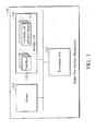
- Fig. 1 is a schematic diagram illustrating an embodiment of a system for operational interface management of the invention
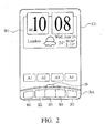
- Fig. 2 is a schematic diagram illustrating an embodiment of an example of an interface of the invention
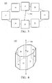
- Fig. 3 is a schematic diagram illustrating an embodiment of an example of an interface circle of the invention.
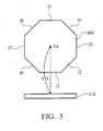
- Fig. 4 is a schematic diagram illustrating an embodiment of an example of a virtual 3D polyhedron of the invention.
- Fig. 5 is a schematic diagram illustrating a concept of a virtual distance between a predefined axle and a screen
- Fig. 6A is a schematic diagram illustrating an embodiment of an example of a screen view for a portrait mode of the invention
- Fig. 6B is a schematic diagram illustrating an embodiment of an example of a screen view for a landscape mode of the invention.
- Fig. 7 is a flowchart of an embodiment of a method for operational interface management of the invention.
- Fig. 8 is a flowchart of an embodiment of a method for determining a virtual distance and a background of the invention.
- Figs. 9A to 9D are schematic diagrams illustrating an embodiment of an example of spinning of the virtual 3D polyhedron of the invention.
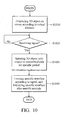
- Fig. 10 is a flowchart of another embodiment of a method for operational interface management of the invention.
- Fig. 11 is a schematic diagram illustrating an embodiment of an example of an interface with multiple display layers of the invention.
- Figs. 12A-12C are schematic diagrams illustrating embodiments of examples of a screen displaying various candidate tilt interface images corresponding to the interface in Fig. 11 of the invention.
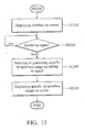
- Fig. 13 is a flowchart of an embodiment of a method for operational interface management of the invention.
- Fig. 14 is a flowchart of another embodiment of a method for operational interface management of the invention.
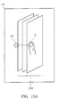
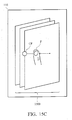
- Figs. 15A-15C are schematic diagrams illustrating an embodiment of an example of transition for the rotation of an interface.
- Fig. 1 is a schematic diagram illustrating an embodiment of a system for operational interface management of the invention.
- the system for operational interface management can be used in an electronic device, such as a PDA (Personal Digital Assistant), a smart phone, a mobile phone, an MID (Mobile Internet Device, MID), a laptop computer, a car computer, a digital camera, a multi-media player, a game device, or any other type of mobile computational device, however, it is to be understood that the invention is not limited thereto.
- PDA Personal Digital Assistant
- a smart phone such as a PDA (Personal Digital Assistant), a smart phone, a mobile phone, an MID (Mobile Internet Device, MID), a laptop computer, a car computer, a digital camera, a multi-media player, a game device, or any other type of mobile computational device, however, it is to be understood that the invention is not limited thereto.
- MID Mobile Internet Device
- the system for operational interface management 100 comprises a screen 110, a storage unit 120, and a processing unit 130.
- the screen 110 can display related data, such as texts, figures, interfaces, and/or related information. It is understood that, in some embodiments, the screen 110 may be integrated with a touch-sensitive device (not shown).
- the touch-sensitive device has a touch-sensitive surface comprising sensors in at least one dimension to detect contact and movement of at least one object (input tool), such as a pen/stylus or finger near or on the touch-sensitive surface. Accordingly, users would be able to input related commands or signals via the screen.
- the storage unit 120 comprises a plurality of interfaces 121. It is understood that, in some embodiments, the respective interface may be a page defined in Android system.
- the respective interface may include a menu of the electronic device. It is noted that, in some embodiments, the interfaces can form an extended desktop, and the respective interface is a part of the extended desktop. It is understood that, in some embodiments, the respective interface can be implemented with multiple display layers, wherein a plurality of objects of the respective interface are deployed to be displayed in different display layers, such that a 3D visual effect can be viewed via the screen. In some embodiments, the respective interfaces can comprise at least one widget, at least one application icon, and/or at least one button.
- Fig. 2 is a schematic diagram illustrating an embodiment of an example of an interface of the invention. As shown in Fig.
- the interface 121 shows a widget W1, four application shortcuts A1 ⁇ A4, and five button B1 ⁇ B5, wherein the widget W1 can obtain related data, and perform related operations to show related results on the interface 121, and related applications or functions can be activated when the application shortcuts or the buttons are selected.
- the plurality of interfaces 121 may be arranged to form a 3D object, such as an interface circle 300, as shown in Fig. 3 , or a virtual 3D polyhedron 400, as shown in Fig. 4 .
- Fig. 11 is a schematic diagram illustrating an embodiment of an example of an interface with multiple display layers of the invention.
- the interface 1100 has three display layers L1, L2 and L3, in which object O1 is deployed to be displayed in the display layer L1, object 02 is deployed to be displayed in the display layer L2, and object 03 is deployed to be displayed in the display layer L3.
- object O1 is deployed to be displayed in the display layer L1
- object 02 is deployed to be displayed in the display layer L2
- object 03 is deployed to be displayed in the display layer L3.
- 3D visual effects can be viewed via the screen.
- the respective interfaces may have 3D tilt effects during the rotation of the respective interfaces when the interface are switched.
- the storage unit 120 may comprise a plurality of candidate tilt interface images 122 for the respective interface.
- the combination of the candidate tilt interface images 122 may show the transition for the rotation of the interface.
- the respective candidate tilt interface images can be corresponded to a respective interface which is to be rotated at various angles.
- candidate tilt interface images corresponding to the interface of Fig. 11 to be rotated, from right to left, at 20°, 45° and 80° are respectively shown in Figs. 12A , 12B and 12C .
- the candidate tilt interface images can be generated in advance.
- one of the candidate tilt interface images can be selected and displayed in the screen 110 according to a distance of the movement. It is noted that, in some embodiments, the distance of the movement of the object continuously detected on the screen 110 can be directly corresponded to a specific candidate tilt interface image.
- the distance of the movement of the object continuously detected on the screen 110 can be first corresponded to a specific angel, and a specific candidate tilt interface image can be corresponded according to the specific angel.
- a 3D graphic engine can be employed to dynamically generate a tilt interface image corresponding to the respective interfaces according to a distance of a movement of an object continuously detected on the screen 110.
- the tilt interface image may correspond to an interface which is to be rotated at a specific angle.
- the plurality of interfaces 121 may be arranged to form a 3D object, such as an interface circle 300, as shown in Fig. 3 , or a virtual 3D polyhedron 400, as shown in Fig. 4 .
- a 3D object such as an interface circle 300, as shown in Fig. 3
- the interfaces I1 ⁇ I8 are arranged in sequence, and the interface circle 300 has a predefined axle SA, in which the interface circle 300 can be spun with respect to the predefined axle SA.
- the plurality of interfaces 121 may be arranged to form a virtual 3D polyhedron 400, as shown in Fig. 4 . It is noted that, in the example of Fig.
- the interfaces I1 ⁇ I8 are arranged in sequence, and form the surfaces of the virtual 3D polyhedron 400 except for the surfaces which are perpendicular to a predefined axle SA of the virtual 3D polyhedron 400, in which the virtual 3D polyhedron 400 can be spun with respect to the predefined axle SA.
- an indicator IN showing a relative position of an interface currently displayed on the screen 110 among the plurality of interfaces 121 can be also displayed in the interface, as shown in Fig. 2 . It is understood that, in some embodiments, when the interface are switched, the indicator IN will accordingly move to indicate the interface currently being viewed on the screen. In some embodiments, the indicator IN will move in the opposite direction of the object such as a finger movement on the screen.
- the processing unit 130 can perform the method for interface management of the present invention, which will be discussed further in the following paragraphs. It is noted that, the processing unit 130 can display the 3D object, such as the interface circle or the virtual 3D polyhedron on the screen 110. Note that, a concept of a virtual distance, used to determine where the 3D object should be located behind and away from the screen will be introduced. That is, the 3D object is located at the virtual distance behind the screen 110. For example, as shown in Fig. 5 , the virtual 3D polyhedron 400 can be located at a virtual distance VD behind the screen 110. It is understood that, in some embodiments, the virtual distance VD is a distance from the screen 110 to the predefined axle SA.
- the virtual distance VD can dynamically adjust a size of the virtual 3D polyhedron 400 to be viewed on the screen 110.
- the virtual 3D polyhedron 400 will be viewed as being small when the virtual distance is being large, and the virtual 3D polyhedron 400 will be viewed as being large when the virtual distance is small.
- the virtual distance between the predefined axle of the 3D object, such as the interface circle or the virtual 3D polyhedron and the screen 110 can be set to a first value
- the virtual distance between the predefined axle of the 3D object, such as the interface circle or the virtual 3D polyhedron and the screen 110 can be set to a second value, in which the second value is greater than the first value, such that only one interface is displayed on the screen 110 when the browsing mode of the electronic device is the portrait mode, as shown in Fig.
- an interface which is completely displayed means the whole interface is displayed, and an interface which is partially displayed means only a part of the interface is displayed.
- the 3D object such as the interface circle or the virtual 3D polyhedron can be spun with respect to the predefined axle SA. During the spinning of the 3D object, the virtual distance between the predefined axle SA of the 3D object and the screen 110 will be varied, which will be discussed further in the following paragraphs.
- a virtual distance between a predefined axle of a 3D object, such as an interface circle or a virtual 3D polyhedron and a screen of the electronic device is determined.
- the 3D object may comprise a plurality of interfaces which are placed, in sequence, in a circle across a 3D space.
- the respective interface may be a page defined in Android system.
- the respective interface may include a menu of the electronic device.
- the interfaces can form an extended desktop, and the respective interface is a part of the extended desktop.
- the respective interface can be implemented with multiple display layers, wherein a plurality of objects of the respective interface are deployed to be displayed in different display layers, such that a 3D visual effect can be viewed via the screen.
- the respective interface can comprise at least one widget, at least one application icon, and/or at least one button.
- the virtual distance can be predefined or determined according to various requirements or applications.
- the virtual distance can be determined according to the browsing mode of the electronic device.
- Fig. 8 is a flowchart of an embodiment of a method for determining a virtual distance and a background of the invention. In step S810, the browsing mode of the electronic device is detected.
- the virtual distance is determined according to the browsing mode of the electronic device. It is understood that, in some embodiments, when the browsing mode of the electronic device is a portrait mode, the virtual distance can be set to a first value, and when the browsing mode of the electronic device is a landscape mode, the virtual distance can be set to a second value, in which the second value is greater than the first value. It is noted that, the 3D object, such as the interface circle or the virtual 3D polyhedron will be viewed as being small when the virtual distance is large, and the 3D object, such as the interface circle or the virtual 3D polyhedron will be viewed as being large when the virtual distance is small.
- only one interface is displayed on the screen when the browsing mode of the electronic device is the portrait mode, and one completely displayed interface and two partially displayed interfaces which are adjacent to the completely displayed interface are displayed on the screen when the browsing mode of the electronic device is the landscape mode.
- an interface which is completely displayed means the whole interface is displayed, and an interface which is partially displayed means only a part of the interface is displayed.
- a specific portion is cropped from wallpaper according to the browsing mode of the electronic device.
- the specific portion of the wallpaper will be displayed as background of the interface. It is understood that, in some embodiments, when users switch between the interfaces, the background wallpaper will not slide. Meanwhile, the size of the wallpaper and the cropping, when it is set to the wallpaper, should change.
- the wallpaper may have an equal height and length, such as 1024x1024.
- the center part of the wallpaper is cropped and used as background and the left/right part of the wallpaper is not used.
- the center part of the wallpaper is cropped and used as background and the upper/lower part of the wallpaper is not used. It is understood that, step S830 can be selectively performed according to various requirements and applications.
- step S720 the 3D object, such as the interface circle or the virtual 3D polyhedron is displayed on the screen according to the determined virtual distance.
- the 3D object is located at the determined virtual distance behind the screen.
- a default interface will be displayed on the screen when the electronic device is activated, or a specific interface will be displayed on the screen when the electronic device is resumed from a specific state, in which the specific interface is the final interface of the specific state.
- the browsing mode of the electronic device will be continuously detected, and the virtual distance will be dynamically adjusted when the browsing mode of the electronic device is changed.
- step S730 it is determined whether a signal has been received.
- the signal may be a gesture of an object on the screen.
- the gesture is used to trigger the electronic device to perform an interface switch operation.
- the gesture may comprise a distance, a contact time corresponding to the object on the screen, and a velocity determined based on the distance and the contact time. If no signal is received (No in step S730), the procedure remains at step S730. If a signal is received (Yes in step S730), in step S740, the 3D object, such as the interface circle or the virtual 3D polyhedron is spun with respect to the predefined axle, wherein the virtual distance varies gradually according to the signal during the spinning of the 3D object. It is understood that, in some embodiments, during the spinning of the 3D object, the 3D object can be stopped when a long contact on the screen is detected.
- Figs. 9A to 9D are schematic diagrams illustrating an embodiment of an example of spinning of the virtual 3D polyhedron of the invention. Initially, the virtual 3D polyhedron is located at a virtual distance VD behind the screen, as shown in Fig. 5 .
- the specific value of the virtual distance can be determined as a virtual distance VD2 based on the signal.
- the 3D object is located at a virtual distance VD1 ( Fig. 9A ) behind the screen, and located at a farthest virtual distance VD2 ( Fig. 9B ) behind the screen.
- the 3D object is closed to the screen, wherein the 3D object is located at a virtual distance VD3 ( Fig. 9C ) behind the screen, and finally located at the initial virtual distance VD ( Fig.
- a spinning velocity of the spinning of the virtual 3D polyhedron can vary, and the spinning velocity of the spinning of the virtual 3D polyhedron can be from a first velocity, determined, based on the signal to 0. That is, during the spinning of the interface circle or the virtual 3D polyhedron, users can view that the spinning velocity of the interface circle or the virtual 3D polyhedron is gradually decreasing. As described, the farthest virtual distance (specific value) can be determined based on the velocity of the signal.
- a specific interface can be located among the plurality of interfaces based on the signal, and the specific interface is displayed on the screen after the spinning of the virtual 3D polyhedron (when the virtual 3D polyhedron is stopped).
- a 3D graphic engine can be employed to dynamically generate at least one frame/picture corresponding to the transition for the spinning of the 3D object, such as the interface circle or the virtual 3D polyhedron by inputting related parameters, such as the various virtual distances of the interface circle or the virtual 3D polyhedron, the number of frames/pictures expected to be generated, the spinning velocity, and/or the located specific interface.
- the frames/pictures corresponding to the transition for the spinning of the interface circle or the virtual 3D polyhedron can be generated in advance for various situations, and stored in a database.
- related frames/pictures can be accordingly retrieved from the database for playback.
- Fig. 10 is a flowchart of another embodiment of a method for interface management of the invention.
- the method for interface management can be used in an electronic device, such as a PDA, a smart phone, a mobile phone, an MID, a laptop computer, a car computer, a digital camera, a multi-media player, a game device, or any other type of mobile computational device, however, it is to be understood that the invention is not limited thereto.
- a 3D object such as an interface circle or a virtual 3D polyhedron is displayed on the screen according to a virtual distance.
- the 3D object may comprise a plurality of interfaces which are placed, in sequence, in a circle across a 3D space.
- the respective interface may be a page defined in Android system.
- the respective interface may include a menu of the electronic device.
- the interfaces can form an extended desktop, and the respective interface is a part of the extended desktop.
- the respective interface can be implemented with multiple display layers, wherein a plurality of objects of the respective interface are deployed to be displayed in different display layers, such that a 3D visual effect can be viewed via the screen.
- the respective interface can comprise at least one widget, at least one application icon, and/or at least one button.
- a default interface will be displayed on the screen when the electronic device is activated, or a specific interface will be displayed on the screen when the electronic device is resumed from a specific state, in which the specific interface is the final interface of the specific state.
- the virtual distance can be used to determine where the 3D object should be located behind away from the screen.
- the 3D object is located behind the screen, and a predefined axle of the 3D object is away from the screen with the virtual distance.
- the virtual distance can be predefined or determined according to various requirements or applications.
- the virtual distance can be determined according to the browsing mode of the electronic device.
- the browsing mode of the electronic device will be continuously detected, and the virtual distance will be dynamically adjusted when the browsing mode of the electronic device is changed.
- the signal may be a gesture of an object on the screen. The gesture is used to trigger the electronic device to perform an interface switch operation.
- the gesture may comprise a distance, a contact time corresponding to the object on the screen, and a velocity determined, based on the distance and the contact time. If no signal is received (No in step S1020), the procedure remains at step S1020. If a signal is received (Yes in step S1020), in step S1030, the 3D object, such as the interface circle or the virtual 3D polyhedron is spun with respect to the predefined axle for a specific period, wherein the virtual distance varies gradually according to the signal during the spinning of the 3D object.
- the specific period can be fixed. It is understood that, in some embodiments, the specific period can be determined, based on the signal. For example, when the velocity corresponding to the input signal is fast, the specific period is long, and when the velocity corresponding to the input signal is slow, the specific period is short.
- the virtual distance varies gradually from a first predefined value, such as the first value in the portrait mode to a specific value, determined, based on the velocity, for example, of the signal, before finally returning back to the virtual distance of the first predefined value. That is, during the spinning of the 3D object, users can view that the 3D object is first far away from the screen, and then closer to the screen.
- a spinning velocity of the spinning of the 3D object can vary, and the spinning velocity of the spinning of the 3D object can be from a first velocity, determined, based on the signal to 0. That is, during the spinning of the 3D object, users can view that the spinning velocity of the 3D object is gradually decreasing. It is understood that, in some embodiments, more circles will be spun when the velocity of the signal is high, and less circles will be spun when the velocity of the signal is slow. It is understood that, a specific interface can be located among the plurality of interfaces based on the signal. After the specific period is ended (the spinning of the 3D object), in step S1040, the specific interface is displayed on the screen. Similarly, in some embodiments, during the spinning of the 3D object, the 3D object can be stopped when a long contact on the screen is detected.
- a 3D graphic engine can be employed to dynamically generate at least one frame/picture corresponding to the transition for the spinning of the 3D object, such as the interface circle or the virtual 3D polyhedron by inputting related parameters, such as the various virtual distances of the 3D object, the number of frames/pictures expected to be generated, the spinning velocity, the specific period, and/or the located specific interface.
- the frames/pictures corresponding to the transition for the spinning of the3D object can be generated in advance for various situations, and stored in a database.
- related frames/pictures can be accordingly retrieved from the database for playback.
- Fig. 13 is a flowchart of an embodiment of a method for interface management of the invention.
- the method for operational interface management can be used in an electronic device, such as a PDA, a smart phone, a mobile phone, an MID, a laptop computer, a car computer, a digital camera, a multi-media player, a game device, or any other type of mobile computational device, however, it is to be understood that the invention is not limited thereto.
- 3D tilt effects for respective interfaces can be viewed via the screen.
- an interface is displayed on the screen. It is understood that, in some embodiments, several interfaces can be placed, in sequence, in a circle across a 3D space, to form a 3D object, such as an interface circle or a virtual 3D polyhedron, as described above. It is understood that, in some embodiments, the respective interface may be a page defined in Android system. In some embodiments, the respective interface may include a menu of the electronic device. It is noted that, in some embodiments, the interfaces can form an extended desktop, and the respective interface is a part of the extended desktop.
- the respective interface can be implemented with multiple display layers, wherein a plurality of objects of the respective interface are deployed to be displayed in different display layers, such that a 3D visual effect can be viewed via the screen.
- the respective interface can comprise at least one widget, at least one application icon, and/or at least one button.
- a default interface will be displayed on the screen when the electronic device is activated, or a specific interface will be displayed on the screen when the electronic device is resumed from a specific state, in which the specific interface is the final interface of the specific state.
- step S1320 it is determined whether a signal has been received.
- the signal may be a movement of an object on the screen.
- the movement is used to trigger the electronic device to perform an interface rotation/switch operation.
- the 3D object such as the interface circle or the virtual 3D polyhedron can be rotated.
- the movement may comprise a distance. If no signal is received (No in step S1320), the procedure remains at step S1320. If a signal is received (Yes in step S1320), in step S1330, a specific tilt interface image is dynamically generated or selected from a plurality of candidate tilt interface images generated in advance according to the signal.
- a 3D graphic engine can be employed to dynamically generate a tilt interface image corresponding to a respective interface according to the distance of the movement of the object.
- the tilt interface image may correspond to an interface which is to be rotated at a specific angle.
- a plurality of candidate tilt interface images corresponding to a respective interface can be generated in advance for various angles, and stored in a database of the storage unit. The combination of the candidate tilt interface images may show the transitions for the rotation of the interface.
- one of the candidate tilt interface images can be selected and displayed in the screen according to the distance of the movement.
- the distance of the movement of the object continuously detected on the screen 110 can be directly corresponded to a specific candidate tilt interface image.
- the distance of the movement of the object continuously detected on the screen 110 can be first corresponded to a specific angel, and a specific candidate tilt interface image can be corresponded according to the specific angel. After the specific tilt interface image is generated or selected, in step S1340, the specific tilt interface image is displayed on the screen.
- the candidate tilt interface image corresponding to the interface of Fig. 11 to be rotated, from right to left, at 20° is retrieved, and displayed on the screen, as shown in Fig. 12A .
- the candidate tilt interface image corresponding to the interface of Fig. 11 to be rotated, from right to left, at 45° is retrieved, and displayed on the screen, as shown in Fig. 12B .
- the candidate tilt interface image corresponding to the interface of Fig. 11 to be rotated, from right to left, at 80° is retrieved, and displayed on the screen, as shown in Fig. 12C .
- Fig. 14 is a flowchart of another embodiment of a method for interface management of the invention.
- the method for operational interface management can be used in an electronic device, such as a PDA, a smart phone, a mobile phone, an MID, a laptop computer, a car computer, a digital camera, a multi-media player, a game device, or any other type of mobile computational device, however, it is to be understood that the invention is not limited thereto.
- 3D tilt effects for respective interfaces can be viewed via the screen, and the transitions for the rotation of the interface can be dynamically displayed based on the movement of an object on the screen.
- an interface is displayed on the screen.
- several interfaces can be placed, in sequence, in a circle across a 3D space, to form a 3D object, such as an interface circle or a virtual 3D polyhedron, as described above.
- the respective interface may be a page defined in Android system.
- the respective interface may include a menu of the electronic device.
- the interfaces can form an extended desktop, and the respective interface is a part of the extended desktop.
- the respective interface can be implemented with multiple display layers, wherein a plurality of objects of the respective interface are deployed to be displayed in different display layers, such that a 3D visual effect can be viewed via the screen.
- the respective interface can comprise at least one widget, at least one application icon, and/or at least one button.
- a default interface will be displayed on the screen when the electronic device is activated, or a specific interface will be displayed on the screen when the electronic device is resumed from a specific state, in which the specific interface is the final interface of the specific state.
- step S1420 a movement of an object on the screen is detected.
- the movement is used to trigger the electronic device to perform an interface rotation/switch operation.
- the 3D object such as the interface circle or the virtual 3D polyhedron can be accordingly rotated.
- a specific tilt interface image is dynamically generated or selected from a plurality of candidate tilt interface images generated in advance according to a distance of the movement.
- a 3D graphic engine can be employed to dynamically generate a tilt interface image corresponding to a respective interface according to the distance of the movement of the object.
- the tilt interface image may correspond to an interface which is to be rotated at a specific angle.
- a plurality of candidate tilt interface images corresponding to a respective interface can be generated in advance for various angles, and stored in a database of the storage unit.
- the combination of the candidate tilt interface images may show the transitions for the rotation of the interface.
- one of the candidate tilt interface images can be selected and displayed in the screen according to the distance of the movement.
- the distance of the movement of the object continuously detected on the screen 110 can be directly corresponded to a specific candidate tilt interface image.
- the distance of the movement of the object continuously detected on the screen 110 can be first corresponded to a specific angel, and a specific candidate tilt interface image can be corresponded according to the specific angel.
- step S1440 the specific tilt interface image is displayed on the screen.
- step S1450 it is determined whether the object is continuously detected on the screen. When the object is continuously detected on the screen (the object is still on the screen) (Yes in step S1450), the procedure returns to step S1430, wherein another specific tilt interface image can be dynamically generated or selected from the candidate tilt interface images according to new distance of the movement of the object. When the object is no longer detected on the screen (No in step S1450), the procedure is terminated. It is understood that, in some embodiments, after the trigger of the signal (movement of the object), another interface placed adjacent to the interface can be displayed on the screen.
- a first tilt interface image corresponding to an interface 1500 to be rotated at a first angle, such as 20° is displayed on the screen 110, as shown in Fig. 15A .
- a second tilt interface image corresponding to the interface 1500 to be rotated at a second angle, such as 80° is displayed on the screen 110, as shown in Fig. 15B .
- a third tilt interface image corresponding to the interface 1500 to be rotated at a third angle, such as 10° is displayed on the screen 110, as shown in Fig. 15C .
- the specific angle can be determined based on the distance between the contact point CP and the final position of the finger F.
- the methods and systems for operational interface management can display interfaces of an electronic device with 3D visual effects, and 3D tilt effects when the interface are rotated, thus, enhancing the value of devices and increasing user experience.
- Methods for operational interface management may take the form of a program code (i.e., executable instructions) embodied in tangible media, such as floppy diskettes, CD-ROMS, hard drives, or any other machine-readable storage medium, wherein, when the program code is loaded into and executed by a machine, such as a computer, the machine thereby becomes an apparatus for practicing the methods.
- the methods may also be embodied in the form of a program code transmitted over some transmission medium, such as electrical wiring or cabling, through fiber optics, or via any other form of transmission, wherein, when the program code is received and loaded into and executed by a machine, such as a computer, the machine becomes an apparatus for practicing the disclosed methods.
- the program code When implemented on a general-purpose processor, the program code combines with the processor to provide a unique apparatus that operates analogously to application specific logic circuits.
Landscapes
- Engineering & Computer Science (AREA)
- General Engineering & Computer Science (AREA)
- Theoretical Computer Science (AREA)
- Human Computer Interaction (AREA)
- Physics & Mathematics (AREA)
- General Physics & Mathematics (AREA)
- User Interface Of Digital Computer (AREA)
- Telephone Function (AREA)
Abstract
Methods and systems for interface management are provided. First, at least one interface is provided and displayed on a screen of the electronic device. The interface is a page or a menu. A plurality of candidate tilt interface images corresponding to the interface are provided, wherein the respective candidate tilt interface images correspond to the interface which is to be rotated at various angles. Then, a signal including a movement of an object continuously detected on the screen is received. In response to the signal, one of the candidate tilt interface images is selected as a specific tilt interface image according to a distance corresponding to the movement of the object on the screen, and the specific tilt interface image is displayed on the screen.
Description
- The disclosure relates generally to interface browsing, and, more particularly to methods and systems for interface management that display interfaces of an electronic device with 3D (three-dimensional) tilt effects when the interface are rotated.
- Recently, portable devices, such as handheld devices, have become more and more technically advanced and multifunctional. For example, a handheld device may have telecommunications capabilities, e-mail message capabilities, an advanced address book management system, a media playback system, and various other functions. Due to increased convenience and functions of the devices, these devices have become necessities of life.
- Generally, a handheld device can install a large amount of functions which are implemented as widgets, applications, virtual or physical buttons, or any other kind of executable program code. Due to the size limitation of screens or other classification requirements, several interfaces, such as menus or pages can be provided in the handheld device. Users can perform a switch operation to switch between the interfaces by using a virtual or physical key, or a touch-sensitive screen.
- Conventionally, the arrangement and display of the interface are uninteresting. For example, the interfaces are respectively rendered as 2D images, and one of the images representing the interfaces is displayed on the screen. When the switch operation is performed, another image is displayed on the screen to replace the original image. To enhance the value of devices and increase user experience, it is an objective of the present application to provide functional and applicable interface management systems for electronic devices.
- Methods and systems for interface management are provided.
- In an embodiment of a method for interface management, at least one interface is provided and displayed on a screen of the electronic device. The interface is a page or a menu. A plurality of candidate tilt interface images corresponding to the interface are provided, wherein the respective candidate tilt interface images correspond to the interface which is to be rotated at various angles. Then, a signal including a movement of an object continuously detected on the screen is received. In response to the signal, one of the candidate tilt interface images is selected as a specific tilt interface image according to a distance corresponding to the movement of the object on the screen, and the specific tilt interface image is displayed on the screen.
- An embodiment of a system for interface management includes a storage unit, a screen, and a processing unit. The storage unit includes at least one interface and a plurality of candidate tilt interface images corresponding to the interface. The interface is a page or a menu, and the respective candidate tilt interface images correspond to the interface which is to be rotated at various angles. The screen displays the at least one interface. The processing unit receives a signal including a movement of an object continuously detected on the screen is received, and in response to the signal, selects one of the candidate tilt interface images as a specific tilt interface image according to a distance corresponding to the movement of the object on the screen, and displays the specific tilt interface image on the screen.
- In some embodiments, the interface is implemented with multiple display layers, wherein a plurality of objects of the interface are deployed to be displayed in different display layers, such that a 3D visual effect can be viewed via the screen.
- In some embodiments, the at least one interface is placed in a circle across a 3D space to form a 3D object, and when the signal is received, the 3D object is rotated according to the distance of the signal.
- In some embodiments, a specific angle is corresponded based on the distance corresponding to the movement of the object on the screen, and the specific tilt interface image is selected based on the specific angle.
- Methods for operational interface management may take the form of a program code embodied in a tangible media. When the program code is loaded into and executed by a machine, the machine becomes an apparatus for practicing the disclosed method.
- The invention will become more fully understood by referring to the following detailed description with reference to the accompanying drawings, wherein:
-
Fig. 1 is a schematic diagram illustrating an embodiment of a system for operational interface management of the invention; -
Fig. 2 is a schematic diagram illustrating an embodiment of an example of an interface of the invention; -
Fig. 3 is a schematic diagram illustrating an embodiment of an example of an interface circle of the invention; -
Fig. 4 is a schematic diagram illustrating an embodiment of an example of a virtual 3D polyhedron of the invention; -
Fig. 5 is a schematic diagram illustrating a concept of a virtual distance between a predefined axle and a screen; -
Fig. 6A is a schematic diagram illustrating an embodiment of an example of a screen view for a portrait mode of the invention; -
Fig. 6B is a schematic diagram illustrating an embodiment of an example of a screen view for a landscape mode of the invention; -
Fig. 7 is a flowchart of an embodiment of a method for operational interface management of the invention; -
Fig. 8 is a flowchart of an embodiment of a method for determining a virtual distance and a background of the invention; -
Figs. 9A to 9D are schematic diagrams illustrating an embodiment of an example of spinning of the virtual 3D polyhedron of the invention; -
Fig. 10 is a flowchart of another embodiment of a method for operational interface management of the invention; -
Fig. 11 is a schematic diagram illustrating an embodiment of an example of an interface with multiple display layers of the invention; -
Figs. 12A-12C are schematic diagrams illustrating embodiments of examples of a screen displaying various candidate tilt interface images corresponding to the interface inFig. 11 of the invention; -
Fig. 13 is a flowchart of an embodiment of a method for operational interface management of the invention; -
Fig. 14 is a flowchart of another embodiment of a method for operational interface management of the invention; and -
Figs. 15A-15C are schematic diagrams illustrating an embodiment of an example of transition for the rotation of an interface. - Methods and systems for operational interface management are provided.
-
Fig. 1 is a schematic diagram illustrating an embodiment of a system for operational interface management of the invention. The system for operational interface management can be used in an electronic device, such as a PDA (Personal Digital Assistant), a smart phone, a mobile phone, an MID (Mobile Internet Device, MID), a laptop computer, a car computer, a digital camera, a multi-media player, a game device, or any other type of mobile computational device, however, it is to be understood that the invention is not limited thereto. - The system for
operational interface management 100 comprises ascreen 110, astorage unit 120, and aprocessing unit 130. Thescreen 110 can display related data, such as texts, figures, interfaces, and/or related information. It is understood that, in some embodiments, thescreen 110 may be integrated with a touch-sensitive device (not shown). The touch-sensitive device has a touch-sensitive surface comprising sensors in at least one dimension to detect contact and movement of at least one object (input tool), such as a pen/stylus or finger near or on the touch-sensitive surface. Accordingly, users would be able to input related commands or signals via the screen. Thestorage unit 120 comprises a plurality ofinterfaces 121. It is understood that, in some embodiments, the respective interface may be a page defined in Android system. In some embodiments, the respective interface may include a menu of the electronic device. It is noted that, in some embodiments, the interfaces can form an extended desktop, and the respective interface is a part of the extended desktop. It is understood that, in some embodiments, the respective interface can be implemented with multiple display layers, wherein a plurality of objects of the respective interface are deployed to be displayed in different display layers, such that a 3D visual effect can be viewed via the screen. In some embodiments, the respective interfaces can comprise at least one widget, at least one application icon, and/or at least one button.Fig. 2 is a schematic diagram illustrating an embodiment of an example of an interface of the invention. As shown inFig. 2 , theinterface 121 shows a widget W1, four application shortcuts A1∼A4, and five button B1∼B5, wherein the widget W1 can obtain related data, and perform related operations to show related results on theinterface 121, and related applications or functions can be activated when the application shortcuts or the buttons are selected. It is understood that, in some embodiments, the plurality ofinterfaces 121 may be arranged to form a 3D object, such as aninterface circle 300, as shown inFig. 3 , or avirtual 3D polyhedron 400, as shown inFig. 4 . -
Fig. 11 is a schematic diagram illustrating an embodiment of an example of an interface with multiple display layers of the invention. As shown inFig. 11 , theinterface 1100 has three display layers L1, L2 and L3, in which object O1 is deployed to be displayed in the display layer L1, object 02 is deployed to be displayed in the display layer L2, and object 03 is deployed to be displayed in the display layer L3. It is understood that, with deployment of objects in different display layers, 3D visual effects can be viewed via the screen. It is noted that, the respective interfaces may have 3D tilt effects during the rotation of the respective interfaces when the interface are switched. Thestorage unit 120 may comprise a plurality of candidatetilt interface images 122 for the respective interface. The combination of the candidatetilt interface images 122 may show the transition for the rotation of the interface. It is understood that, the respective candidate tilt interface images can be corresponded to a respective interface which is to be rotated at various angles. For example, candidate tilt interface images corresponding to the interface ofFig. 11 to be rotated, from right to left, at 20°, 45° and 80° are respectively shown inFigs. 12A ,12B and12C . In some embodiments, the candidate tilt interface images can be generated in advance. When a movement of an object is continuously detected on thescreen 110, one of the candidate tilt interface images can be selected and displayed in thescreen 110 according to a distance of the movement. It is noted that, in some embodiments, the distance of the movement of the object continuously detected on thescreen 110 can be directly corresponded to a specific candidate tilt interface image. In some embodiments, the distance of the movement of the object continuously detected on thescreen 110 can be first corresponded to a specific angel, and a specific candidate tilt interface image can be corresponded according to the specific angel. Further, in some embodiments, a 3D graphic engine can be employed to dynamically generate a tilt interface image corresponding to the respective interfaces according to a distance of a movement of an object continuously detected on thescreen 110. Similarly, in some embodiments, the tilt interface image may correspond to an interface which is to be rotated at a specific angle. - It is understood that, in some embodiments, the plurality of
interfaces 121 may be arranged to form a 3D object, such as aninterface circle 300, as shown inFig. 3 , or avirtual 3D polyhedron 400, as shown inFig. 4 . It is noted that, in the example ofFig. 3 , the interfaces I1∼I8 are arranged in sequence, and theinterface circle 300 has a predefined axle SA, in which theinterface circle 300 can be spun with respect to the predefined axle SA. In some embodiments, the plurality ofinterfaces 121 may be arranged to form avirtual 3D polyhedron 400, as shown inFig. 4 . It is noted that, in the example ofFig. 4 , the interfaces I1∼I8 are arranged in sequence, and form the surfaces of thevirtual 3D polyhedron 400 except for the surfaces which are perpendicular to a predefined axle SA of thevirtual 3D polyhedron 400, in which thevirtual 3D polyhedron 400 can be spun with respect to the predefined axle SA. - It is understood that, since the plurality of
interfaces 121 are arranged in sequence, in some embodiments, an indicator IN showing a relative position of an interface currently displayed on thescreen 110 among the plurality ofinterfaces 121 can be also displayed in the interface, as shown inFig. 2 . It is understood that, in some embodiments, when the interface are switched, the indicator IN will accordingly move to indicate the interface currently being viewed on the screen. In some embodiments, the indicator IN will move in the opposite direction of the object such as a finger movement on the screen. - The
processing unit 130 can perform the method for interface management of the present invention, which will be discussed further in the following paragraphs. It is noted that, theprocessing unit 130 can display the 3D object, such as the interface circle or the virtual 3D polyhedron on thescreen 110. Note that, a concept of a virtual distance, used to determine where the 3D object should be located behind and away from the screen will be introduced. That is, the 3D object is located at the virtual distance behind thescreen 110. For example, as shown inFig. 5 , thevirtual 3D polyhedron 400 can be located at a virtual distance VD behind thescreen 110. It is understood that, in some embodiments, the virtual distance VD is a distance from thescreen 110 to the predefined axle SA. The virtual distance VD can dynamically adjust a size of thevirtual 3D polyhedron 400 to be viewed on thescreen 110. Thevirtual 3D polyhedron 400 will be viewed as being small when the virtual distance is being large, and thevirtual 3D polyhedron 400 will be viewed as being large when the virtual distance is small. For example, when the browsing mode of the electronic device is a portrait mode, the virtual distance between the predefined axle of the 3D object, such as the interface circle or the virtual 3D polyhedron and thescreen 110 can be set to a first value, and when the browsing mode of the electronic device is a landscape mode, the virtual distance between the predefined axle of the 3D object, such as the interface circle or the virtual 3D polyhedron and thescreen 110 can be set to a second value, in which the second value is greater than the first value, such that only one interface is displayed on thescreen 110 when the browsing mode of the electronic device is the portrait mode, as shown inFig. 6A , and one completely displayed interface and two partially displayed interfaces which are adjacent to the completely displayed interface are displayed on thescreen 110 when the browsing mode of the electronic device is the landscape mode, as shown inFig. 6B . It is noted that, an interface which is completely displayed means the whole interface is displayed, and an interface which is partially displayed means only a part of the interface is displayed. As described, the 3D object, such as the interface circle or the virtual 3D polyhedron can be spun with respect to the predefined axle SA. During the spinning of the 3D object, the virtual distance between the predefined axle SA of the 3D object and thescreen 110 will be varied, which will be discussed further in the following paragraphs. - In step S710, a virtual distance between a predefined axle of a 3D object, such as an interface circle or a virtual 3D polyhedron and a screen of the electronic device is determined. It is understood that, in some embodiments, the 3D object may comprise a plurality of interfaces which are placed, in sequence, in a circle across a 3D space. It is understood that, in some embodiments, the respective interface may be a page defined in Android system. In some embodiments, the respective interface may include a menu of the electronic device. It is noted that, in some embodiments, the interfaces can form an extended desktop, and the respective interface is a part of the extended desktop. It is understood that, in some embodiments, the respective interface can be implemented with multiple display layers, wherein a plurality of objects of the respective interface are deployed to be displayed in different display layers, such that a 3D visual effect can be viewed via the screen. In some embodiments, the respective interface can comprise at least one widget, at least one application icon, and/or at least one button. It is understood that, the virtual distance can be predefined or determined according to various requirements or applications. In some embodiments, the virtual distance can be determined according to the browsing mode of the electronic device.
Fig. 8 is a flowchart of an embodiment of a method for determining a virtual distance and a background of the invention. In step S810, the browsing mode of the electronic device is detected. In step S820, the virtual distance is determined according to the browsing mode of the electronic device. It is understood that, in some embodiments, when the browsing mode of the electronic device is a portrait mode, the virtual distance can be set to a first value, and when the browsing mode of the electronic device is a landscape mode, the virtual distance can be set to a second value, in which the second value is greater than the first value. It is noted that, the 3D object, such as the interface circle or the virtual 3D polyhedron will be viewed as being small when the virtual distance is large, and the 3D object, such as the interface circle or the virtual 3D polyhedron will be viewed as being large when the virtual distance is small. In some embodiments, only one interface is displayed on the screen when the browsing mode of the electronic device is the portrait mode, and one completely displayed interface and two partially displayed interfaces which are adjacent to the completely displayed interface are displayed on the screen when the browsing mode of the electronic device is the landscape mode. Similarly, an interface which is completely displayed means the whole interface is displayed, and an interface which is partially displayed means only a part of the interface is displayed. Then, in step S830, a specific portion is cropped from wallpaper according to the browsing mode of the electronic device. The specific portion of the wallpaper will be displayed as background of the interface. It is understood that, in some embodiments, when users switch between the interfaces, the background wallpaper will not slide. Meanwhile, the size of the wallpaper and the cropping, when it is set to the wallpaper, should change. In some embodiments, the wallpaper may have an equal height and length, such as 1024x1024. In the portrait mode, the center part of the wallpaper is cropped and used as background and the left/right part of the wallpaper is not used. In the landscape mode, the center part of the wallpaper is cropped and used as background and the upper/lower part of the wallpaper is not used. It is understood that, step S830 can be selectively performed according to various requirements and applications. - Referring to
Fig. 7 , in step S720, the 3D object, such as the interface circle or the virtual 3D polyhedron is displayed on the screen according to the determined virtual distance. For example, the 3D object is located at the determined virtual distance behind the screen. It is understood that, in some embodiments, a default interface will be displayed on the screen when the electronic device is activated, or a specific interface will be displayed on the screen when the electronic device is resumed from a specific state, in which the specific interface is the final interface of the specific state. It is understood that, in some embodiments, the browsing mode of the electronic device will be continuously detected, and the virtual distance will be dynamically adjusted when the browsing mode of the electronic device is changed. In step S730, it is determined whether a signal has been received. It is understood that, in some embodiments, the signal may be a gesture of an object on the screen. The gesture is used to trigger the electronic device to perform an interface switch operation. The gesture may comprise a distance, a contact time corresponding to the object on the screen, and a velocity determined based on the distance and the contact time. If no signal is received (No in step S730), the procedure remains at step S730. If a signal is received (Yes in step S730), in step S740, the 3D object, such as the interface circle or the virtual 3D polyhedron is spun with respect to the predefined axle, wherein the virtual distance varies gradually according to the signal during the spinning of the 3D object. It is understood that, in some embodiments, during the spinning of the 3D object, the 3D object can be stopped when a long contact on the screen is detected. - It is understood that, in some embodiments, during the spinning of the 3D object, the virtual distance varies gradually from a first predefined value, such as the first value in the portrait mode to a specific value, determined, based on the velocity, for example, of the signal, before finally returning back to the virtual distance of the first predefined value. That is, during the spinning of the 3D object, users can view that the 3D object is first far away from the screen, and then closer to the screen.
Figs. 9A to 9D are schematic diagrams illustrating an embodiment of an example of spinning of the virtual 3D polyhedron of the invention. Initially, the virtual 3D polyhedron is located at a virtual distance VD behind the screen, as shown inFig. 5 . When a signal is received, the specific value of the virtual distance can be determined as a virtual distance VD2 based on the signal. First, the 3D object is located at a virtual distance VD1 (Fig. 9A ) behind the screen, and located at a farthest virtual distance VD2 (Fig. 9B ) behind the screen. Then, the 3D object is closed to the screen, wherein the 3D object is located at a virtual distance VD3 (Fig. 9C ) behind the screen, and finally located at the initial virtual distance VD (Fig. 9D ) behind the screen, wherein the virtual distance VD2 is greater than the virtual distance VD1 or the virtual distance VD3, and the virtual distance VD1 or the virtual distance VD3 is greater than the initial virtual distance VD. Further, it is understood that, in some embodiments, a spinning velocity of the spinning of the virtual 3D polyhedron can vary, and the spinning velocity of the spinning of the virtual 3D polyhedron can be from a first velocity, determined, based on the signal to 0. That is, during the spinning of the interface circle or the virtual 3D polyhedron, users can view that the spinning velocity of the interface circle or the virtual 3D polyhedron is gradually decreasing. As described, the farthest virtual distance (specific value) can be determined based on the velocity of the signal. It is understood that, in some embodiments, more circles will be spun when the velocity of the signal is high, and less circles will be spun when the velocity of the signal is slow. It is also understood that, in some embodiments, a specific interface can be located among the plurality of interfaces based on the signal, and the specific interface is displayed on the screen after the spinning of the virtual 3D polyhedron (when the virtual 3D polyhedron is stopped). - It is understood that, in some embodiments, a 3D graphic engine can be employed to dynamically generate at least one frame/picture corresponding to the transition for the spinning of the 3D object, such as the interface circle or the virtual 3D polyhedron by inputting related parameters, such as the various virtual distances of the interface circle or the virtual 3D polyhedron, the number of frames/pictures expected to be generated, the spinning velocity, and/or the located specific interface. In some embodiments, the frames/pictures corresponding to the transition for the spinning of the interface circle or the virtual 3D polyhedron can be generated in advance for various situations, and stored in a database. Once related parameters, such as the various virtual distances of the interface circle or the virtual 3D polyhedron, the number of frames/pictures expected to be generated, the spinning velocity, and/or the located specific interface are determined, related frames/pictures can be accordingly retrieved from the database for playback.
-
Fig. 10 is a flowchart of another embodiment of a method for interface management of the invention. The method for interface management can be used in an electronic device, such as a PDA, a smart phone, a mobile phone, an MID, a laptop computer, a car computer, a digital camera, a multi-media player, a game device, or any other type of mobile computational device, however, it is to be understood that the invention is not limited thereto. - In step S1010, a 3D object, such as an interface circle or a virtual 3D polyhedron is displayed on the screen according to a virtual distance. Similarly, in some embodiments, the 3D object may comprise a plurality of interfaces which are placed, in sequence, in a circle across a 3D space. It is understood that, in some embodiments, the respective interface may be a page defined in Android system. In some embodiments, the respective interface may include a menu of the electronic device. It is noted that, in some embodiments, the interfaces can form an extended desktop, and the respective interface is a part of the extended desktop. It is understood that, in some embodiments, the respective interface can be implemented with multiple display layers, wherein a plurality of objects of the respective interface are deployed to be displayed in different display layers, such that a 3D visual effect can be viewed via the screen. In some embodiments, the respective interface can comprise at least one widget, at least one application icon, and/or at least one button. Similarly, in some embodiments, a default interface will be displayed on the screen when the electronic device is activated, or a specific interface will be displayed on the screen when the electronic device is resumed from a specific state, in which the specific interface is the final interface of the specific state. It is understood that, in some embodiments, the virtual distance can be used to determine where the 3D object should be located behind away from the screen. That is, the 3D object is located behind the screen, and a predefined axle of the 3D object is away from the screen with the virtual distance. The virtual distance can be predefined or determined according to various requirements or applications. In some embodiments, the virtual distance can be determined according to the browsing mode of the electronic device. Similarly, in some embodiments, the browsing mode of the electronic device will be continuously detected, and the virtual distance will be dynamically adjusted when the browsing mode of the electronic device is changed. In step S1020, it is determined whether a signal has been received. Similarly, in some embodiments, the signal may be a gesture of an object on the screen. The gesture is used to trigger the electronic device to perform an interface switch operation. The gesture may comprise a distance, a contact time corresponding to the object on the screen, and a velocity determined, based on the distance and the contact time. If no signal is received (No in step S1020), the procedure remains at step S1020. If a signal is received (Yes in step S1020), in step S1030, the 3D object, such as the interface circle or the virtual 3D polyhedron is spun with respect to the predefined axle for a specific period, wherein the virtual distance varies gradually according to the signal during the spinning of the 3D object.
- It is understood that, in some embodiments, the specific period can be fixed. It is understood that, in some embodiments, the specific period can be determined, based on the signal. For example, when the velocity corresponding to the input signal is fast, the specific period is long, and when the velocity corresponding to the input signal is slow, the specific period is short. In some embodiments, during the spinning of the 3D object, the virtual distance varies gradually from a first predefined value, such as the first value in the portrait mode to a specific value, determined, based on the velocity, for example, of the signal, before finally returning back to the virtual distance of the first predefined value. That is, during the spinning of the 3D object, users can view that the 3D object is first far away from the screen, and then closer to the screen. Further, in some embodiments, a spinning velocity of the spinning of the 3D object can vary, and the spinning velocity of the spinning of the 3D object can be from a first velocity, determined, based on the signal to 0. That is, during the spinning of the 3D object, users can view that the spinning velocity of the 3D object is gradually decreasing. It is understood that, in some embodiments, more circles will be spun when the velocity of the signal is high, and less circles will be spun when the velocity of the signal is slow. It is understood that, a specific interface can be located among the plurality of interfaces based on the signal. After the specific period is ended (the spinning of the 3D object), in step S1040, the specific interface is displayed on the screen. Similarly, in some embodiments, during the spinning of the 3D object, the 3D object can be stopped when a long contact on the screen is detected.
- Similarly, in some embodiments, a 3D graphic engine can be employed to dynamically generate at least one frame/picture corresponding to the transition for the spinning of the 3D object, such as the interface circle or the virtual 3D polyhedron by inputting related parameters, such as the various virtual distances of the 3D object, the number of frames/pictures expected to be generated, the spinning velocity, the specific period, and/or the located specific interface. In some embodiments, the frames/pictures corresponding to the transition for the spinning of the3D object can be generated in advance for various situations, and stored in a database. Once related parameters, such as the various virtual distances of the 3D object, the number of frames/pictures expected to be generated, the spinning velocity, the specific period, and/or the located specific interface are determined, related frames/pictures can be accordingly retrieved from the database for playback.
-
Fig. 13 is a flowchart of an embodiment of a method for interface management of the invention. The method for operational interface management can be used in an electronic device, such as a PDA, a smart phone, a mobile phone, an MID, a laptop computer, a car computer, a digital camera, a multi-media player, a game device, or any other type of mobile computational device, however, it is to be understood that the invention is not limited thereto. In the embodiment, 3D tilt effects for respective interfaces can be viewed via the screen. - In step S1310, an interface is displayed on the screen. It is understood that, in some embodiments, several interfaces can be placed, in sequence, in a circle across a 3D space, to form a 3D object, such as an interface circle or a virtual 3D polyhedron, as described above. It is understood that, in some embodiments, the respective interface may be a page defined in Android system. In some embodiments, the respective interface may include a menu of the electronic device. It is noted that, in some embodiments, the interfaces can form an extended desktop, and the respective interface is a part of the extended desktop. It is understood that, in some embodiments, the respective interface can be implemented with multiple display layers, wherein a plurality of objects of the respective interface are deployed to be displayed in different display layers, such that a 3D visual effect can be viewed via the screen. In some embodiments, the respective interface can comprise at least one widget, at least one application icon, and/or at least one button. Similarly, in some embodiments, a default interface will be displayed on the screen when the electronic device is activated, or a specific interface will be displayed on the screen when the electronic device is resumed from a specific state, in which the specific interface is the final interface of the specific state. In step S1320, it is determined whether a signal has been received. It is understood that, in some embodiments, the signal may be a movement of an object on the screen. The movement is used to trigger the electronic device to perform an interface rotation/switch operation. When the signal is received, the 3D object, such as the interface circle or the virtual 3D polyhedron can be rotated. The movement may comprise a distance. If no signal is received (No in step S1320), the procedure remains at step S1320. If a signal is received (Yes in step S1320), in step S1330, a specific tilt interface image is dynamically generated or selected from a plurality of candidate tilt interface images generated in advance according to the signal. Similarly, in some embodiments, a 3D graphic engine can be employed to dynamically generate a tilt interface image corresponding to a respective interface according to the distance of the movement of the object. In some embodiments, the tilt interface image may correspond to an interface which is to be rotated at a specific angle. In some embodiments, a plurality of candidate tilt interface images corresponding to a respective interface can be generated in advance for various angles, and stored in a database of the storage unit. The combination of the candidate tilt interface images may show the transitions for the rotation of the interface. When a movement of an object is detected on the screen, one of the candidate tilt interface images can be selected and displayed in the screen according to the distance of the movement. Similarly, in some embodiments, the distance of the movement of the object continuously detected on the
screen 110 can be directly corresponded to a specific candidate tilt interface image. In some embodiments, the distance of the movement of the object continuously detected on thescreen 110 can be first corresponded to a specific angel, and a specific candidate tilt interface image can be corresponded according to the specific angel. After the specific tilt interface image is generated or selected, in step S1340, the specific tilt interface image is displayed on the screen. - For example, when the
screen 110 currently displays theinterface 1100 inFig. 11 , and a user slides a finger on thescreen 110 with a distance of 1 cm, the candidate tilt interface image corresponding to the interface ofFig. 11 to be rotated, from right to left, at 20° is retrieved, and displayed on the screen, as shown inFig. 12A . When a user slides a finger on thescreen 110 with a distance of 2 cm, the candidate tilt interface image corresponding to the interface ofFig. 11 to be rotated, from right to left, at 45° is retrieved, and displayed on the screen, as shown inFig. 12B . When a user slides a finger on thescreen 110 with a distance of 3 cm, the candidate tilt interface image corresponding to the interface ofFig. 11 to be rotated, from right to left, at 80° is retrieved, and displayed on the screen, as shown inFig. 12C . -
Fig. 14 is a flowchart of another embodiment of a method for interface management of the invention. The method for operational interface management can be used in an electronic device, such as a PDA, a smart phone, a mobile phone, an MID, a laptop computer, a car computer, a digital camera, a multi-media player, a game device, or any other type of mobile computational device, however, it is to be understood that the invention is not limited thereto. In the embodiment, 3D tilt effects for respective interfaces can be viewed via the screen, and the transitions for the rotation of the interface can be dynamically displayed based on the movement of an object on the screen. - In step S1410, an interface is displayed on the screen. Similarly, in some embodiments, several interfaces can be placed, in sequence, in a circle across a 3D space, to form a 3D object, such as an interface circle or a virtual 3D polyhedron, as described above. It is understood that, in some embodiments, the respective interface may be a page defined in Android system. In some embodiments, the respective interface may include a menu of the electronic device. It is noted that, in some embodiments, the interfaces can form an extended desktop, and the respective interface is a part of the extended desktop. It is understood that, in some embodiments, the respective interface can be implemented with multiple display layers, wherein a plurality of objects of the respective interface are deployed to be displayed in different display layers, such that a 3D visual effect can be viewed via the screen. In some embodiments, the respective interface can comprise at least one widget, at least one application icon, and/or at least one button. Similarly, in some embodiments, a default interface will be displayed on the screen when the electronic device is activated, or a specific interface will be displayed on the screen when the electronic device is resumed from a specific state, in which the specific interface is the final interface of the specific state. In step S1420, a movement of an object on the screen is detected. Similarly, in some embodiments, the movement is used to trigger the electronic device to perform an interface rotation/switch operation. When the movement is received, the 3D object, such as the interface circle or the virtual 3D polyhedron can be accordingly rotated. In step S1430, a specific tilt interface image is dynamically generated or selected from a plurality of candidate tilt interface images generated in advance according to a distance of the movement. Similarly, in some embodiments, a 3D graphic engine can be employed to dynamically generate a tilt interface image corresponding to a respective interface according to the distance of the movement of the object. In some embodiments, the tilt interface image may correspond to an interface which is to be rotated at a specific angle. In some embodiments, a plurality of candidate tilt interface images corresponding to a respective interface can be generated in advance for various angles, and stored in a database of the storage unit. The combination of the candidate tilt interface images may show the transitions for the rotation of the interface. When a movement of an object is detected on the screen, one of the candidate tilt interface images can be selected and displayed in the screen according to the distance of the movement. Similarly, in some embodiments, the distance of the movement of the object continuously detected on the
screen 110 can be directly corresponded to a specific candidate tilt interface image. In some embodiments, the distance of the movement of the object continuously detected on thescreen 110 can be first corresponded to a specific angel, and a specific candidate tilt interface image can be corresponded according to the specific angel. After the specific tilt interface image is generated or selected, in step S1440, the specific tilt interface image is displayed on the screen. In step S1450, it is determined whether the object is continuously detected on the screen. When the object is continuously detected on the screen (the object is still on the screen) (Yes in step S1450), the procedure returns to step S1430, wherein another specific tilt interface image can be dynamically generated or selected from the candidate tilt interface images according to new distance of the movement of the object. When the object is no longer detected on the screen (No in step S1450), the procedure is terminated. It is understood that, in some embodiments, after the trigger of the signal (movement of the object), another interface placed adjacent to the interface can be displayed on the screen. - For example, when a user uses a finger F to touch the
screen 110 at a contact point CP, and slides the finger F, from left to right, on thescreen 110, a first tilt interface image corresponding to aninterface 1500 to be rotated at a first angle, such as 20° is displayed on thescreen 110, as shown inFig. 15A . When the user keeps the finger F on thescreen 110, and continuously moves, from left to right, a second tilt interface image corresponding to theinterface 1500 to be rotated at a second angle, such as 80° is displayed on thescreen 110, as shown inFig. 15B . When the user keeps the finger F on thescreen 110, but moves, from right to left, a third tilt interface image corresponding to theinterface 1500 to be rotated at a third angle, such as 10° is displayed on thescreen 110, as shown inFig. 15C . It is understood that, the specific angle can be determined based on the distance between the contact point CP and the final position of the finger F. - Therefore, the methods and systems for operational interface management can display interfaces of an electronic device with 3D visual effects, and 3D tilt effects when the interface are rotated, thus, enhancing the value of devices and increasing user experience.
- Methods for operational interface management, or certain aspects or portions thereof, may take the form of a program code (i.e., executable instructions) embodied in tangible media, such as floppy diskettes, CD-ROMS, hard drives, or any other machine-readable storage medium, wherein, when the program code is loaded into and executed by a machine, such as a computer, the machine thereby becomes an apparatus for practicing the methods. The methods may also be embodied in the form of a program code transmitted over some transmission medium, such as electrical wiring or cabling, through fiber optics, or via any other form of transmission, wherein, when the program code is received and loaded into and executed by a machine, such as a computer, the machine becomes an apparatus for practicing the disclosed methods. When implemented on a general-purpose processor, the program code combines with the processor to provide a unique apparatus that operates analogously to application specific logic circuits.
- While the invention has been described by way of example and in terms of preferred embodiment, it is to be understood that the invention is not limited thereto. Those who are skilled in this technology can still make various alterations and modifications without departing from the scope and spirit of this invention. Therefore, the scope of the present invention shall be defined and protected by the following claims and their equivalent.
Claims (11)
- A method for interface management, for use in an electronic device, comprising:displaying at least one interface (S1310) on a screen of the electronic device, wherein the interface comprise a page or a menu;providing a plurality of candidate tilt interface images corresponding to the interface, wherein the respective candidate tilt interface images correspond to the interface which is to be rotated at various angles;receiving a signal (S1320), wherein the signal comprises a movement of an object continuously detected on the screen; andin response to the signal, selecting one of the candidate tilt interface images (S1330) as a specific tilt interface image according to a distance corresponding to the movement of the object on the screen, and displaying the specific tilt interface image (S 1340) on the screen.
- The method of claim 1, wherein the interface is implemented with multiple display layers, wherein a plurality of objects of the interface are deployed to be displayed in different display layers, such that a 3D visual effect can be viewed via the screen.
- The method of claims 1 or 2, wherein the at least one interface is placed in a circle across a 3D space to form a 3D object, and when the signal is received, the 3D object is rotated according to the distance of the signal.
- The method of one or more of the claims 1 to 3, wherein the interface comprises at least one widget, at least one application icon, or at least one button.
- The method of one or more of the claims 1 to 4, further comprising:corresponding to a specific angle based on the distance corresponding to the movement of the object on the screen; andselecting the specific tilt interface image based on the specific angle.
- A system (100) for interface management for use in an electronic device, comprising:a storage unit (120) comprising at least one interface and a plurality of candidate tilt interface images corresponding to the at least one interface, wherein the interface comprise a page or a menu, and the respective candidate tilt interface images correspond to the interface which is to be rotated at various angle;a screen (110) displaying the at least one interface; anda processing unit (130) receiving a signal, wherein the signal comprises a movement of an object continuously detected on the screen, and in response to the signal, selecting one of the candidate tilt interface images as a specific tilt interface image according to a distance corresponding to the movement of the object on the screen, and displaying the specific tilt interface image on the screen.
- The system of claim 6, wherein the interface is implemented with multiple display layers, wherein a plurality of objects of the interface are deployed to be displayed in different display layers, such that a 3D visual effect can be viewed via the screen.
- The system of claims 6 or 7, wherein the at least one interface is placed in a circle across a 3D space to form a 3D object, and when the signal is received, the processing unit rotates the 3D object according to the distance of the signal.
- The system of one or more of the claims 6 to 8, wherein the interface comprises at least one widget, at least one application icon, or at least one button.
- The system of one or more of the claims 6 to 9, wherein the processing unit further corresponds to a specific angle based on the distance corresponding to the movement of the object on the screen, and selects the specific tilt interface image based on the specific angle.
- A machine-readable storage medium comprising a computer program, which, when executed, causes a device to perform a method for interface management, wherein the method comprises:displaying at least one interface on a screen of the electronic device, wherein the interface comprise a page or a menu;providing a plurality of candidate tilt interface images corresponding to the interface, wherein the respective candidate tilt interface images correspond to the interface which is to be rotated at various angles;receiving a signal, wherein the signal comprises a movement of an object continuously detected on the screen; andin response to the signal, selecting one of the candidate tilt interface images as a specific tilt interface image according to a distance corresponding to the movement of the object on the screen, and displaying the specific tilt interface image on the screen.
Applications Claiming Priority (1)
| Application Number | Priority Date | Filing Date | Title |
|---|---|---|---|
| US13/102,600 US20120284668A1 (en) | 2011-05-06 | 2011-05-06 | Systems and methods for interface management |
Publications (1)
| Publication Number | Publication Date |
|---|---|
| EP2521019A1 true EP2521019A1 (en) | 2012-11-07 |
Family
ID=44278599
Family Applications (1)
| Application Number | Title | Priority Date | Filing Date |
|---|---|---|---|
| EP11169515A Ceased EP2521019A1 (en) | 2011-05-06 | 2011-06-10 | Systems and methods for interface management |
Country Status (2)
| Country | Link |
|---|---|
| US (1) | US20120284668A1 (en) |
| EP (1) | EP2521019A1 (en) |
Families Citing this family (12)
| Publication number | Priority date | Publication date | Assignee | Title |
|---|---|---|---|---|
| USD687056S1 (en) * | 2011-08-16 | 2013-07-30 | Nest Labs, Inc. | Display screen with an animated graphical user interface |
| USD698812S1 (en) * | 2012-06-04 | 2014-02-04 | Microsoft Corporation | Display screen with animated graphical user interface |
| US9430991B2 (en) * | 2012-10-02 | 2016-08-30 | Futurewei Technologies, Inc. | User interface display composition with device sensor/state based graphical effects |
| USD742916S1 (en) * | 2013-02-07 | 2015-11-10 | Htc Corporation | Portion of a display screen with a graphical user interface |
| US8982472B2 (en) * | 2013-05-21 | 2015-03-17 | Matvey Lvovskiy | Method of widening of angular field of view of collimating optical systems |
| CN104166497A (en) * | 2014-06-13 | 2014-11-26 | 广州市久邦数码科技有限公司 | Three-dimensional desktop shortcut bar and switching method thereof |
| USD792896S1 (en) | 2015-07-08 | 2017-07-25 | Mitsubishi Electric Corporation | Display screen with animated graphical user interface |
| US11402981B2 (en) | 2017-08-11 | 2022-08-02 | Samsung Electronics Co., Ltd. | Display device for visualizing contents as the display is rotated and control method thereof |
| KR102373510B1 (en) * | 2017-08-11 | 2022-03-11 | 삼성전자주식회사 | Display device for visualizing contents as the display is rotated and control method thereof |
| US12321562B2 (en) * | 2022-06-13 | 2025-06-03 | Illuscio, Inc. | Systems and methods for interacting with three-dimensional graphical user interface elements to control computer operation |
| CN116048352A (en) * | 2022-07-29 | 2023-05-02 | 荣耀终端有限公司 | Display diagram switching method and electronic device |
| EP4579414A1 (en) * | 2023-12-29 | 2025-07-02 | Seat, S.A. | A computer-implemented method and a computer program for operating a touchsensitive display, and a touch-sensitive display |
Citations (5)
| Publication number | Priority date | Publication date | Assignee | Title |
|---|---|---|---|---|
| US20030184576A1 (en) * | 2002-03-29 | 2003-10-02 | Vronay David P. | Peek around user interface |
| US20080062141A1 (en) * | 2006-09-11 | 2008-03-13 | Imran Chandhri | Media Player with Imaged Based Browsing |
| US20090064012A1 (en) * | 2007-09-04 | 2009-03-05 | Apple Inc. | Animation of graphical objects |
| US20100295958A1 (en) * | 2009-05-20 | 2010-11-25 | Sony Ericsson Mobile Communications Ab | Portable electronic apparatus including a display and method for controlling such an apparatus |
| US20110083078A1 (en) * | 2009-10-01 | 2011-04-07 | Ju Seok-Hoon | Mobile terminal and browsing method thereof |
Family Cites Families (3)
| Publication number | Priority date | Publication date | Assignee | Title |
|---|---|---|---|---|
| US7663620B2 (en) * | 2005-12-05 | 2010-02-16 | Microsoft Corporation | Accessing 2D graphic content using axonometric layer views |
| US7581186B2 (en) * | 2006-09-11 | 2009-08-25 | Apple Inc. | Media manager with integrated browsers |
| KR101608764B1 (en) * | 2009-07-14 | 2016-04-04 | 엘지전자 주식회사 | Mobile terminal and method for controlling display thereof |
-
2011
- 2011-05-06 US US13/102,600 patent/US20120284668A1/en not_active Abandoned
- 2011-06-10 EP EP11169515A patent/EP2521019A1/en not_active Ceased
Patent Citations (5)
| Publication number | Priority date | Publication date | Assignee | Title |
|---|---|---|---|---|
| US20030184576A1 (en) * | 2002-03-29 | 2003-10-02 | Vronay David P. | Peek around user interface |
| US20080062141A1 (en) * | 2006-09-11 | 2008-03-13 | Imran Chandhri | Media Player with Imaged Based Browsing |
| US20090064012A1 (en) * | 2007-09-04 | 2009-03-05 | Apple Inc. | Animation of graphical objects |
| US20100295958A1 (en) * | 2009-05-20 | 2010-11-25 | Sony Ericsson Mobile Communications Ab | Portable electronic apparatus including a display and method for controlling such an apparatus |
| US20110083078A1 (en) * | 2009-10-01 | 2011-04-07 | Ju Seok-Hoon | Mobile terminal and browsing method thereof |
Also Published As
| Publication number | Publication date |
|---|---|
| US20120284668A1 (en) | 2012-11-08 |
Similar Documents
| Publication | Publication Date | Title |
|---|---|---|
| EP2521020A1 (en) | Systems and methods for interface management | |
| KR102365615B1 (en) | Mobile device of bangle type, and methods for controlling and diplaying ui thereof | |
| US20120284668A1 (en) | Systems and methods for interface management | |
| US12477058B2 (en) | Device, method, and graphical user interface for updating a background for home and wake screen user interfaces | |
| KR102224349B1 (en) | User termincal device for displaying contents and methods thereof | |
| JP7321197B2 (en) | Information processing device, information processing method, and computer program | |
| US20240184442A1 (en) | Devices, Methods, and Systems for Manipulating User Interfaces | |
| JP5742187B2 (en) | Information processing apparatus, information processing method, and program | |
| JP4720879B2 (en) | Information processing apparatus and information processing method | |
| US11269483B2 (en) | Device, method, and graphical user interface for managing content items and associated metadata | |
| US12307082B2 (en) | Scrollable set of content items with locking feature | |
| KR20220024386A (en) | Mobile device of bangle type, and methods for controlling and diplaying ui thereof | |
| KR102384310B1 (en) | Device, method, and graphical user interface for navigating media content | |
| EP3102998B1 (en) | Device, method, and graphical user interface for a predictive keyboard | |
| US9313406B2 (en) | Display control apparatus having touch panel function, display control method, and storage medium | |
| JP2015508211A (en) | Method and apparatus for controlling a screen by tracking a user's head through a camera module and computer-readable recording medium thereof | |
| US20130179837A1 (en) | Electronic device interface | |
| TWI496106B (en) | Interface display system and method | |
| CA2782786A1 (en) | Electronic device interface | |
| WO2014143633A1 (en) | Device, method, and graphical user interface for orientation-based parallax dispaly | |
| CN104854549A (en) | Display device and method thereof | |
| US9665249B1 (en) | Approaches for controlling a computing device based on head movement | |
| JP2012155506A (en) | Information terminal and screen component selection method | |
| JP2015527626A (en) | UI providing method and portable device to which UI is applied | |
| US10585485B1 (en) | Controlling content zoom level based on user head movement |
Legal Events
| Date | Code | Title | Description |
|---|---|---|---|
| PUAI | Public reference made under article 153(3) epc to a published international application that has entered the european phase |
Free format text: ORIGINAL CODE: 0009012 |
|
| 17P | Request for examination filed |
Effective date: 20110615 |
|
| AK | Designated contracting states |
Kind code of ref document: A1 Designated state(s): AL AT BE BG CH CY CZ DE DK EE ES FI FR GB GR HR HU IE IS IT LI LT LU LV MC MK MT NL NO PL PT RO RS SE SI SK SM TR |
|
| AX | Request for extension of the european patent |
Extension state: BA ME |
|
| 17Q | First examination report despatched |
Effective date: 20130730 |
|
| STAA | Information on the status of an ep patent application or granted ep patent |
Free format text: STATUS: THE APPLICATION HAS BEEN REFUSED |
|
| 18R | Application refused |
Effective date: 20140618 |