EP2520841A1 - Axially swaged fitting - Google Patents
Axially swaged fitting Download PDFInfo
- Publication number
- EP2520841A1 EP2520841A1 EP12160069A EP12160069A EP2520841A1 EP 2520841 A1 EP2520841 A1 EP 2520841A1 EP 12160069 A EP12160069 A EP 12160069A EP 12160069 A EP12160069 A EP 12160069A EP 2520841 A1 EP2520841 A1 EP 2520841A1
- Authority
- EP
- European Patent Office
- Prior art keywords
- sleeve
- metal
- fitting
- swaging
- ring
- Prior art date
- Legal status (The legal status is an assumption and is not a legal conclusion. Google has not performed a legal analysis and makes no representation as to the accuracy of the status listed.)
- Granted
Links
Images



Classifications
-
- F—MECHANICAL ENGINEERING; LIGHTING; HEATING; WEAPONS; BLASTING
- F16—ENGINEERING ELEMENTS AND UNITS; GENERAL MEASURES FOR PRODUCING AND MAINTAINING EFFECTIVE FUNCTIONING OF MACHINES OR INSTALLATIONS; THERMAL INSULATION IN GENERAL
- F16L—PIPES; JOINTS OR FITTINGS FOR PIPES; SUPPORTS FOR PIPES, CABLES OR PROTECTIVE TUBING; MEANS FOR THERMAL INSULATION IN GENERAL
- F16L13/00—Non-disconnectable pipe joints, e.g. soldered, adhesive, or caulked joints
- F16L13/14—Non-disconnectable pipe joints, e.g. soldered, adhesive, or caulked joints made by plastically deforming the material of the pipe, e.g. by flanging, rolling
- F16L13/146—Non-disconnectable pipe joints, e.g. soldered, adhesive, or caulked joints made by plastically deforming the material of the pipe, e.g. by flanging, rolling by an axially moveable sleeve
-
- Y—GENERAL TAGGING OF NEW TECHNOLOGICAL DEVELOPMENTS; GENERAL TAGGING OF CROSS-SECTIONAL TECHNOLOGIES SPANNING OVER SEVERAL SECTIONS OF THE IPC; TECHNICAL SUBJECTS COVERED BY FORMER USPC CROSS-REFERENCE ART COLLECTIONS [XRACs] AND DIGESTS
- Y10—TECHNICAL SUBJECTS COVERED BY FORMER USPC
- Y10T—TECHNICAL SUBJECTS COVERED BY FORMER US CLASSIFICATION
- Y10T29/00—Metal working
- Y10T29/49—Method of mechanical manufacture
- Y10T29/49826—Assembling or joining
Definitions
- the present disclosure relates to fluid fittings for connection to tubes and pipes by swaging and, more particularly, to a swagable fitting having an axially movable swaging ring for applying radial swaging force.
- Permanent fittings are commonly used for connecting metal tubes and pipes to eachother for use in a variety of applications, for example for the conveyance of hydraulic control fluids in the aerospace industry.
- the connection between the tubes and fitting must be secure in order to withstand vibrations and adverse conditions.
- axially swaged fitting such as the Rynglok (trademarked product) fittings manufactured by Eaton Corporation.
- Other axially swaged fittings are available and utilize substantially similar construction and methods to swage the fitting onto a tube.
- Another example of these axially swaged fittings are the Permalite (trademarked product) brand from Permaswage.
- These axially swaged fittings utilize a sleeve surrounding the tubes to be joined and one or more swaging ring about the sleeve. The ring and sleeve have complimentary geometry such that as the swaging ring is positioned onto the sleeve, the sleeve collapses the tube to thereby swage the pieces together.
- a lubricant may be placed between the sleeve and swaging ring, thereby allowing the swaging process by reducing friction between the ring and sleeve. This reduces the chance of scarring or gouging the surface of either the ring or sleeve which may cause the swaging ring to lock up and be unable to complete the swaging process, or may damage the ring or sleeve.
- the wing of an aircraft requires a number of hydraulic control lines to operate control structure on that portion of the aircraft. These control lines require a significant amount of open space, and may therefore be passed through the fuel storage sections on the wings of the aircraft. There are therefore a large number of fittings adjacent the fuel of the aircraft, and therefore care must be taken to ensure a secure and safe connection.
- Prior art axially swaged fittings do not address this problem, and therefore may be unsuitable for providing a complete conductive path from one tube to another through the swaged fitting. It is therefore a principal object of the present disclosure to provide an axially swaged fitting which provides a complete conductive path through metal components to eliminate the risk of sparking or heat buildup in an axially swaged fitting.
- the apparatus may be used in other applications including, without limitation, watercraft, space vehicles, submarines, automobiles, buildings, industrial hydraulic lines, unmanned vehicles, or any other application.
- the apparatus may also be used for other, non-hydraulic systems in the same manner as traditional swaged fittings.
- an axially swaged fitting for joining to a tube is disclosed.
- the fitting consists of a sleeve that fits about the tube and a ring that fits about the sleeve.
- the ring is adapted to slide over the sleeve to thereby deform the sleeve and tube, thereby creating a permanent metal-to-metal electrically bonded joint.
- the sleeve preferably includes a hard or soft metal layer, while the ring includes the other of a soft or hard metal layer, so that the soft metal is deformed during the swaging process.
- a method for connecting a fitting to a tube by axially swaging includes the steps of providing a tube, a swaging sleeve, and a swaging ring, positioning the tube within the sleeve and the ring about the sleeve and tube, and axially swaging the ring onto the sleeve, thereby deforming the tube and forming a mechanical joint.
- the inner surface of the ring and outer surface of the sleeve are selected to be opposing hard and soft metals.
- a method of making an axially swageable fitting includes the steps of providing a sleeve and a ring adapted to be joined together by axial swaging.
- a sleeve mating metal is applied to the outside surface of the sleeve and a ring mating metal is applied to the inner surface of the ring.
- the sleeve and ring mating metal are selected so that one is a hard metal and the other is a soft metal.
- a method of connecting a fitting to a tube by axially swaging comprising the steps of: providing a tube; providing a sleeve having an outer surface, the outer surface including a mating metal layer comprising a hard or soft metal; providing a ring having an inner surface, wherein the inner surface forms a mechanical interference with the outer surface, the inner surface including a ring metal layer comprising the other of a hard or soft metal; positioning the tube within the sleeve; positioning the ring about the sleeve and the tube; and axially swaging the ring onto the sleeve to deform the tube, thereby forming a mechanical joint.
- said soft metal is selected from a group consisting of: aluminum, copper, gallium, silver, cadmium, indium, tin, antimony, platinum, gold, thallium, bismuth, lead, an alloy of the foregoing, and certain steel alloys.
- said hard metal is selected from the group consisting of: vanadium, chromium, nickel, rhodium, palladium, and tantalum.
- said sleeve further includes an annular groove. Further comprising the step of providing a tool for axially swaging said ring onto said sleeve, and further comprising the step of positioning said tool onto said annular ring and an end of said ring.
- Figure 1 illustrates an airplane 100 having a fuselage 102 and wing 104. Extending from the fuselage 102 are a number of hydraulic lines 106 which pass through a portion of the wing 104 which traditionally includes fuel storage. These hydraulic lines 106 are used to control flaps 108 on the wing, and may include a number of fittings 110, as shown in Fig. 2 .
- While the present apparatus is shown in the context of airplanes, it will be understood by those having skill in the art that this apparatus may be utilized in other applications. Such applications include, without limitation, industrial hydraulic systems, automotive components, or other hydraulic applications. The apparatus may also be used in non-hydraulic systems, and may replace any other swaged fitting as appropriate.
- Fig. 2 shows a closer detail of the wing 104 and the location of fittings 110 along the hydraulic lines 106.
- Figs. 3A-B shows a view of the fitting 110 for use in connecting first 112 and second 114 tubes to each other in axial alignment.
- the fitting generally consists of a substantially cylindrical sleeve 116 with an outer surface 118, inner surface 120, and an axial bore 122 ( Fig. 5 ) for receiving the tubes 112, 114.
- the fitting 110 further includes a swaging ring 124 which may be swaged onto the sleeve 116 to permanently secure the tubes 112, 114 thereto.
- the sleeve 116 has a symmetrical configuration opposite an annular grove 126.
- annular grove 126 For ease of reference and shown in Fig. 5 , only one of these portions will be described. It will be understood that the opposite side of the sleeve 116 is structurally and functionally identical to the side described. It is also to be understood that the fitting may be constructed of one or more of these configurations.
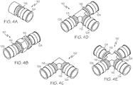
- Figures 4A-E show several (non-exclusive) examples of these arrangements, including a fitting with a single swaged end ( Fig. 4A ), a straight fitting ( Fig. 4B ), an elbow fitting ( Fig. 4C ), a tee fitting ( Fig. 4D ) and a cross fitting ( Fig. 4E ). Joining of multiple portions may be accomplished according to means well known in the art.
- Fig. 5 shows one embodiment of one portion of the sleeve 116 in closer detail.
- the portion of the sleeve 116 extends between an inner end 128 and an outer end 130.
- An outer surface 118 forms the exterior of the cylindrical sleeve 116 and an inner surface 120 defines an axial bore 122 for receiving a tube 112 ( Fig. 3A ).
- An annular groove 126 is positioned adjacent the inner end 128.
- annular lip 132 which extends about the sleeve 116 and provides a grip for a swaging tool to swage the swaging ring 124 (see Fig. 3A ) and sleeve 116.
- first surface 134 Adjacent to the annular lip 132 is a first surface 134 extending towards the outer end 130.
- This first surface 134 portion of the sleeve 116 has a smaller diameter than that of the annular lip 132.
- the first surface 134 is stepped to a second surface 136, the second surface 136 having a smaller diameter than the first surface 134.
- This second surface 136 extends from the first surface 134 to the outer end 130 of the sleeve 116.
- Each of the first surface 134 and second surface 136 surfaces may have a substantially constant diameter, or alternatively may taper from a larger diameter at the inner end 128 towards a smaller diameter towards the outer end 130.
- the sleeve 116 may include annular ridges to provide mechanical locking for the swaging ring 124 (see Fig. 6 ).
- Other arrangements of a mechanical interference fit that are known in the art may be substitute for the above-described arrangement.
- the inner surface 120 of the sleeve 116 may also include unique geometry.
- the inner surface 120 may include two or more annular gaps 138, 140 axially spaced apart from one another. These annular gaps 138, 140 provide space for the material of the tube 112, 114 ( Fig. 3B ) to be displaced into when the swaging ring 124 is swaged in place.
- the use and function of such annular gaps138, 140 are well known and described in the prior art.
- Other gap geometry or means for causing the sleeve 116 to securely engage the tube 112 are known and may be substituted for annular gaps 138, 140, such means will be readily apparent to those skilled in the art.
- Fig. 6 shows a further detail of one of the swaging rings 124 used to secure the sleeve 116 to the tube 112 ( Fig. 3A ).
- the swaging ring 124 generally comprises a cylindrical shape having a central opening 142 for receiving the sleeve 116.
- the central opening 142 further includes a receiving surface 144 and a gap 146 for fitting over the annular lip 132 (see Fig. 5 ).
- the receiving surface 144 is shown having a curved or wavy circumference, however it will be appreciated that this surface may be textured, tapered, flat, or otherwise adapted to engage and deform the sleeve 116 ( Fig.
- a swaging tool (not shown) grips the outer edge 148 of the ring 124 to move it over the sleeve 116, thereby swaging the sleeve 116 and tube 112, 114.
- a sleeve 116 is provided with swaging rings 124 positioned on either end of the sleeve 116.
- the receiving surface 144 ( Fig. 6 ) is positioned adjacent the second surface 136 ( Fig. 5 ).
- a tube 112, 114 is inserted into the sleeve through the swaging ring 124.
- a swaging tool (not shown) grips the annular lip 132 ( Fig. 5 ) of the sleeve 116 and the outer edge 148 ( Fig. 6 ) of the swaging ring 124.
- the tool then draws the swaging ring 124 and sleeve 116 together so that the annular lip 132 of the sleeve 116 is positioned within the gap 146 of the swaging ring 124.
- the receiving surface 144 is drawn onto the first surface 134 which deforms into the tube 112, 114. This arrangement is shown in Fig. 3B .
- a lubricant (not shown) may also be placed between the swaging ring 124 and sleeve 116 to encourage the swaging process.
- the receiving surface 144 ( Fig. 6 ) of the swaging ring 124 moves from the second surface 136 to the first surface 134.
- the receiving surface 144 of the swaging ring has a progressively diminishing diameter, and as it engages the first surface 134, the sleeve 116 is compressed into the tube 112, 114.
- the annular gaps 138, 140 of the sleeve ( Fig. 5 ) encourage this deformation, which pinches the tube 112, 114 into an hourglass shape that inhibits movement of the tube 112, 114 from the sleeve 116.
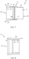
- the sleeve 116 may be structurally identical to the previous description, but comprise an outer layer 150 as a slip surface applied onto the inner material 152 that forms the sleeve 116.
- the outer layer 150 may be made of a hard metal, examples of hard metals include a group comprising vanadium, chromium, nickel, rhodium, palladium, tantalum, and certain steel alloys.
- the inner material 152 constitutes the remainder of the sleeve and may be selected for resistance to hydraulic pressure, and may be selected from a group comprising titanium, aluminum, CRES, or other material.
- One method of applying the outer layer 150 to the inner material 152 is by electrostatic plating, although other methods are well known in the art.
- the swaging ring 124 may be structurally identical to the previous description, but comprise an outer material 154 and inner layer 156.
- the swaging ring 124 is preferably formed entirely of the outer material 154 except for the inner layer 156.
- the outer material 154 is selected for it's resistance to forces due to hydraulic pressure and swaging, and may be constructed from a group comprising titanium, aluminum, CRES, or other material.
- the inner layer 156 is manufactured from a metal which is soft relative to the hard metal of the outer layer 150 of the sleeve 116.
- soft metals include a group comprising aluminum, copper, gallium, silver, cadmium, indium, tin, antimony, platinum, gold, thallium, bismuth, lead, alloys of the foregoing, and certain steel alloys.
- the inner layer 156 may be applied to the swaging ring 124 by, for example, electrostatic plating, although other methods of forming a relatively thin layer of metal are well known in the art.
- Providing a hard metal outer material 150 on the sleeve 116 provides a rub surface that resists scarring that may occur if the ring and sleeve are uniform materials.
- the soft metal of the inner layer 156 of the swaging ring 124 provides a slip surface that will scar as the swaging ring 124 slides over the sleeve 116.
- This mating metal layer arrangement ensures continuous metal-to-metal contact between the ring and sleeve, thereby creating a constant electrical path so that when there is an electrical event, current may be transferred directly from the sleeve 116 to the ring 124.
- the swaging ring 124 and sleeve 116 have been generally described as including a layer of either a hard or soft metal. However, it is also contemplated that the entire sleeve 116 or ring 124 may be constructed of either a hard or soft metal as described. The proportion of the sleeve 116 and/or ring 124 that includes a hard or soft metal may be determined according to the particular use to which the product is applied, and may range from a narrow strip to the entire sleeve 116 or ring 124. The arrangement of both portions of the sleeve 116 and ring 124 may be different, again according to use.
- the Rynglok fittings have been described and serve as an example of the type of axially swaged fitting which may be utilized with this disclosure.
- Other variations of axially swaged fittings may be used without departing from the scope of the disclosure.
- the above-cited Permalite brand of fittings may be utilized.
- These fittings may differ in form from the described Rynglok fittings (for example, omitting gap 146, although other structure may be added or removed from the fitting), but function similarly by axially swaging the fitting to the tube.
- the slip and rub surfaces may be switched, so that the hard metal rub surface is located on the swaging ring 124 while the soft metal slip surface is located on the sleeve 116.
Landscapes
- Engineering & Computer Science (AREA)
- General Engineering & Computer Science (AREA)
- Mechanical Engineering (AREA)
- Mutual Connection Of Rods And Tubes (AREA)
Abstract
Description
- The present disclosure relates to fluid fittings for connection to tubes and pipes by swaging and, more particularly, to a swagable fitting having an axially movable swaging ring for applying radial swaging force.
- Permanent fittings are commonly used for connecting metal tubes and pipes to eachother for use in a variety of applications, for example for the conveyance of hydraulic control fluids in the aerospace industry. In this application, the connection between the tubes and fitting must be secure in order to withstand vibrations and adverse conditions.
- One type of commonly used fitting is an axially swaged fitting, such as the Rynglok (trademarked product) fittings manufactured by Eaton Corporation. Other axially swaged fittings are available and utilize substantially similar construction and methods to swage the fitting onto a tube. Another example of these axially swaged fittings are the Permalite (trademarked product) brand from Permaswage. These axially swaged fittings utilize a sleeve surrounding the tubes to be joined and one or more swaging ring about the sleeve. The ring and sleeve have complimentary geometry such that as the swaging ring is positioned onto the sleeve, the sleeve collapses the tube to thereby swage the pieces together.
- In order to effectuate the swaging process, a lubricant may be placed between the sleeve and swaging ring, thereby allowing the swaging process by reducing friction between the ring and sleeve. This reduces the chance of scarring or gouging the surface of either the ring or sleeve which may cause the swaging ring to lock up and be unable to complete the swaging process, or may damage the ring or sleeve.
- The wing of an aircraft requires a number of hydraulic control lines to operate control structure on that portion of the aircraft. These control lines require a significant amount of open space, and may therefore be passed through the fuel storage sections on the wings of the aircraft. There are therefore a large number of fittings adjacent the fuel of the aircraft, and therefore care must be taken to ensure a secure and safe connection.
- Electrical events are possible in the hydraulic lines, for example due to system fault or other anomalies in the hydraulic system, and this may cause electrical current to flow along one or more of the tubes. It has previously been assumed that as the electrical current flows from one tube to another through the fitting that the current flows from the first tube, through the sleeve, and then to the second tube, with the swaging rings being outside of the current path. This path of electrical current ensures that current flows cleanly through the fitting without discharges or excess heat buildup.
- However, further investigation has revealed that the swaging rings are within the current path, and current travels from the first tube, through the sleeve, to the first swaging ring, back to the sleeve, to the second swaging ring, back to the sleeve, and finally to the second tube. Any lubrication remaining around or between the swaging rings and sleeve may therefore be within the electrical path. Because of the low electrical conductivity of the lubricant, as current flows through the material it acts as a resistor and heats up. This is undesirable for hydraulic lines which run through a fuel storage area, such as on an airplane. Prior art axially swaged fittings do not address this problem, and therefore may be unsuitable for providing a complete conductive path from one tube to another through the swaged fitting. It is therefore a principal object of the present disclosure to provide an axially swaged fitting which provides a complete conductive path through metal components to eliminate the risk of sparking or heat buildup in an axially swaged fitting.
- While this problem is identified primarily with respect to aircraft, the apparatus may be used in other applications including, without limitation, watercraft, space vehicles, submarines, automobiles, buildings, industrial hydraulic lines, unmanned vehicles, or any other application. The apparatus may also be used for other, non-hydraulic systems in the same manner as traditional swaged fittings.
- Therefore, there is proposed a novel axially swaged fitting which eliminates the problems of the prior art.
- According to one embodiment of the disclosure, an axially swaged fitting for joining to a tube is disclosed. The fitting consists of a sleeve that fits about the tube and a ring that fits about the sleeve. The ring is adapted to slide over the sleeve to thereby deform the sleeve and tube, thereby creating a permanent metal-to-metal electrically bonded joint. The sleeve preferably includes a hard or soft metal layer, while the ring includes the other of a soft or hard metal layer, so that the soft metal is deformed during the swaging process.
- Also disclosed is a method for connecting a fitting to a tube by axially swaging. This method includes the steps of providing a tube, a swaging sleeve, and a swaging ring, positioning the tube within the sleeve and the ring about the sleeve and tube, and axially swaging the ring onto the sleeve, thereby deforming the tube and forming a mechanical joint. The inner surface of the ring and outer surface of the sleeve are selected to be opposing hard and soft metals.
- According to a further embodiment, a method of making an axially swageable fitting is described. The method includes the steps of providing a sleeve and a ring adapted to be joined together by axial swaging. A sleeve mating metal is applied to the outside surface of the sleeve and a ring mating metal is applied to the inner surface of the ring. The sleeve and ring mating metal are selected so that one is a hard metal and the other is a soft metal.
- According to a further embodiment there is described a method of connecting a fitting to a tube by axially swaging comprising the steps of: providing a tube; providing a sleeve having an outer surface, the outer surface including a mating metal layer comprising a hard or soft metal; providing a ring having an inner surface, wherein the inner surface forms a mechanical interference with the outer surface, the inner surface including a ring metal layer comprising the other of a hard or soft metal; positioning the tube within the sleeve; positioning the ring about the sleeve and the tube; and axially swaging the ring onto the sleeve to deform the tube, thereby forming a mechanical joint. Wherein said soft metal is selected from a group consisting of: aluminum, copper, gallium, silver, cadmium, indium, tin, antimony, platinum, gold, thallium, bismuth, lead, an alloy of the foregoing, and certain steel alloys. Wherein said hard metal is selected from the group consisting of: vanadium, chromium, nickel, rhodium, palladium, and tantalum. Wherein said sleeve further includes an annular groove. Further comprising the step of providing a tool for axially swaging said ring onto said sleeve, and further comprising the step of positioning said tool onto said annular ring and an end of said ring.
- The features, functions, and advantages that have been discussed can be achieved independently in various embodiments of the present invention or may be combined in yet other embodiments further details of which can be seen with reference to the following description and drawings.
-
-
Fig. 1 is a perspective view of an aircraft with a cutaway view of the wing. -
Fig. 2 is a top cutaway view of the aircraft wing in further detail. -
Fig. 3A is a side cutaway view of the pre-swaged fitting. -
Fig. 3B is a side cutaway view of the swaged fitting. -
Fig. 4A is a top plan view of one embodiment. -
Fig. 4B is a top plan view of an alternative embodiment. -
Fig. 4C is a top plan view of an alternative embodiment. -
Fig. 4D is a top plan view of an alternative embodiment. -
Fig. 4E is a top plan view of an alternative embodiment. -
Fig. 5 is a side cutaway view of a portion of the sleeve. -
Fig. 6 is a side cutaway view of the swaging ring. -
Fig. 7 is a side cutaway view of the sleeve according to an alternative embodiment. -
Fig. 8 is a side cutaway view of the ring according to an alternative embodiment. -
Figure 1 illustrates anairplane 100 having afuselage 102 andwing 104. Extending from thefuselage 102 are a number ofhydraulic lines 106 which pass through a portion of thewing 104 which traditionally includes fuel storage. Thesehydraulic lines 106 are used to controlflaps 108 on the wing, and may include a number offittings 110, as shown inFig. 2 . - While the present apparatus is shown in the context of airplanes, it will be understood by those having skill in the art that this apparatus may be utilized in other applications. Such applications include, without limitation, industrial hydraulic systems, automotive components, or other hydraulic applications. The apparatus may also be used in non-hydraulic systems, and may replace any other swaged fitting as appropriate.
-
Fig. 2 shows a closer detail of thewing 104 and the location offittings 110 along thehydraulic lines 106. -
Figs. 3A-B shows a view of the fitting 110 for use in connecting first 112 and second 114 tubes to each other in axial alignment. The fitting generally consists of a substantiallycylindrical sleeve 116 with anouter surface 118,inner surface 120, and an axial bore 122 (Fig. 5 ) for receiving thetubes swaging ring 124 which may be swaged onto thesleeve 116 to permanently secure thetubes - As further shown in
Fig. 3A , thesleeve 116 has a symmetrical configuration opposite anannular grove 126. For ease of reference and shown inFig. 5 , only one of these portions will be described. It will be understood that the opposite side of thesleeve 116 is structurally and functionally identical to the side described. It is also to be understood that the fitting may be constructed of one or more of these configurations. -
Figures 4A-E show several (non-exclusive) examples of these arrangements, including a fitting with a single swaged end (Fig. 4A ), a straight fitting (Fig. 4B ), an elbow fitting (Fig. 4C ), a tee fitting (Fig. 4D ) and a cross fitting (Fig. 4E ). Joining of multiple portions may be accomplished according to means well known in the art. -
Fig. 5 shows one embodiment of one portion of thesleeve 116 in closer detail. As shown, the portion of thesleeve 116 extends between aninner end 128 and anouter end 130. Anouter surface 118 forms the exterior of thecylindrical sleeve 116 and aninner surface 120 defines anaxial bore 122 for receiving a tube 112 (Fig. 3A ). Anannular groove 126 is positioned adjacent theinner end 128. Immediately adjacent theannular groove 126 is anannular lip 132 which extends about thesleeve 116 and provides a grip for a swaging tool to swage the swaging ring 124 (seeFig. 3A ) andsleeve 116. Adjacent to theannular lip 132 is afirst surface 134 extending towards theouter end 130. Thisfirst surface 134 portion of thesleeve 116 has a smaller diameter than that of theannular lip 132. At a point between theinner end 128 andouter end 130, thefirst surface 134 is stepped to asecond surface 136, thesecond surface 136 having a smaller diameter than thefirst surface 134. Thissecond surface 136 extends from thefirst surface 134 to theouter end 130 of thesleeve 116. Each of thefirst surface 134 andsecond surface 136 surfaces may have a substantially constant diameter, or alternatively may taper from a larger diameter at theinner end 128 towards a smaller diameter towards theouter end 130. Alternatively, thesleeve 116 may include annular ridges to provide mechanical locking for the swaging ring 124 (seeFig. 6 ). Other arrangements of a mechanical interference fit that are known in the art may be substitute for the above-described arrangement. - The
inner surface 120 of thesleeve 116 may also include unique geometry. Theinner surface 120 may include two or moreannular gaps annular gaps tube 112, 114 (Fig. 3B ) to be displaced into when theswaging ring 124 is swaged in place. The use and function of such annular gaps138, 140 are well known and described in the prior art. Other gap geometry or means for causing thesleeve 116 to securely engage thetube 112 are known and may be substituted forannular gaps -
Fig. 6 shows a further detail of one of the swaging rings 124 used to secure thesleeve 116 to the tube 112 (Fig. 3A ). As shown, theswaging ring 124 generally comprises a cylindrical shape having a central opening 142 for receiving thesleeve 116. The central opening 142 further includes a receivingsurface 144 and agap 146 for fitting over the annular lip 132 (seeFig. 5 ). The receivingsurface 144 is shown having a curved or wavy circumference, however it will be appreciated that this surface may be textured, tapered, flat, or otherwise adapted to engage and deform the sleeve 116 (Fig. 3A ) so as to secure the tube 112 (Fig 3A ) by axial swaging. A swaging tool (not shown) grips theouter edge 148 of thering 124 to move it over thesleeve 116, thereby swaging thesleeve 116 andtube - The process of axial swaging is generally shown in
Figs. 3A-3B . First, asleeve 116 is provided with swaging rings 124 positioned on either end of thesleeve 116. As shown inFig. 3A , the receiving surface 144 (Fig. 6 ) is positioned adjacent the second surface 136 (Fig. 5 ). Next, atube swaging ring 124. Finally, a swaging tool (not shown) grips the annular lip 132 (Fig. 5 ) of thesleeve 116 and the outer edge 148 (Fig. 6 ) of theswaging ring 124. The tool then draws theswaging ring 124 andsleeve 116 together so that theannular lip 132 of thesleeve 116 is positioned within thegap 146 of theswaging ring 124. As theswaging ring 124 is drawn onto thesleeve 116, the receivingsurface 144 is drawn onto thefirst surface 134 which deforms into thetube Fig. 3B . A lubricant (not shown) may also be placed between theswaging ring 124 andsleeve 116 to encourage the swaging process. - As shown in
Fig. 3B , as theswaging ring 124 engages thesleeve 116 in an axial direction, the receiving surface 144 (Fig. 6 ) of theswaging ring 124 moves from thesecond surface 136 to thefirst surface 134. The receivingsurface 144 of the swaging ring has a progressively diminishing diameter, and as it engages thefirst surface 134, thesleeve 116 is compressed into thetube annular gaps Fig. 5 ) encourage this deformation, which pinches thetube tube sleeve 116. - As shown in
Fig. 7 , thesleeve 116 may be structurally identical to the previous description, but comprise anouter layer 150 as a slip surface applied onto theinner material 152 that forms thesleeve 116. Theouter layer 150 may be made of a hard metal, examples of hard metals include a group comprising vanadium, chromium, nickel, rhodium, palladium, tantalum, and certain steel alloys. Theinner material 152 constitutes the remainder of the sleeve and may be selected for resistance to hydraulic pressure, and may be selected from a group comprising titanium, aluminum, CRES, or other material. One method of applying theouter layer 150 to theinner material 152 is by electrostatic plating, although other methods are well known in the art. - As shown in
Fig. 8 , theswaging ring 124 may be structurally identical to the previous description, but comprise anouter material 154 andinner layer 156. Theswaging ring 124 is preferably formed entirely of theouter material 154 except for theinner layer 156. Theouter material 154 is selected for it's resistance to forces due to hydraulic pressure and swaging, and may be constructed from a group comprising titanium, aluminum, CRES, or other material. Theinner layer 156 is manufactured from a metal which is soft relative to the hard metal of theouter layer 150 of thesleeve 116. Examples of soft metals include a group comprising aluminum, copper, gallium, silver, cadmium, indium, tin, antimony, platinum, gold, thallium, bismuth, lead, alloys of the foregoing, and certain steel alloys. As with thesleeve 116, theinner layer 156 may be applied to theswaging ring 124 by, for example, electrostatic plating, although other methods of forming a relatively thin layer of metal are well known in the art. - Providing a hard metal
outer material 150 on thesleeve 116 provides a rub surface that resists scarring that may occur if the ring and sleeve are uniform materials. In contrast, the soft metal of theinner layer 156 of theswaging ring 124 provides a slip surface that will scar as theswaging ring 124 slides over thesleeve 116. This mating metal layer arrangement ensures continuous metal-to-metal contact between the ring and sleeve, thereby creating a constant electrical path so that when there is an electrical event, current may be transferred directly from thesleeve 116 to thering 124. - The
swaging ring 124 andsleeve 116 have been generally described as including a layer of either a hard or soft metal. However, it is also contemplated that theentire sleeve 116 orring 124 may be constructed of either a hard or soft metal as described. The proportion of thesleeve 116 and/orring 124 that includes a hard or soft metal may be determined according to the particular use to which the product is applied, and may range from a narrow strip to theentire sleeve 116 orring 124. The arrangement of both portions of thesleeve 116 andring 124 may be different, again according to use. - As previously described, the Rynglok fittings have been described and serve as an example of the type of axially swaged fitting which may be utilized with this disclosure. Other variations of axially swaged fittings may be used without departing from the scope of the disclosure. For example, the above-cited Permalite brand of fittings may be utilized. These fittings may differ in form from the described Rynglok fittings (for example, omitting
gap 146, although other structure may be added or removed from the fitting), but function similarly by axially swaging the fitting to the tube. - According to an alternative embodiment, the slip and rub surfaces may be switched, so that the hard metal rub surface is located on the
swaging ring 124 while the soft metal slip surface is located on thesleeve 116.
Claims (14)
- An axially swaged fitting (110) for joining to a tube (112,114), the fitting comprising a sleeve (116) and a swaging ring (124) adapted to slide over the sleeve (116) when forced in an axial direction to deform said sleeve (116) and said tube (112, 114) to thereby create a swaged joint, wherein a mating metal layer of one of the sleeve and swaging ring comprises one of a hard or soft metal and a mating metal layer of the other of the sleeve(116) and swaging ring (124) comprises the other of a hard or soft metal so that the soft metal is deformed during the swaging process.
- The fitting (110) of claim 1 wherein the mating metal layer of the sleeve (116) comprises a hard metal.
- The fitting (110) of claim 2 wherein the mating metal layer of the swaging ring (124) comprises a soft metal.
- The fitting (110) of claim 3 wherein the hard metal is selected from a group consisting of: vanadium, chromium, nickel, rhodium, palladium, and tantalum.
- The fitting (110) of claim 4 wherein the soft metal is selected from a group consisting of: aluminum, copper, gallium, silver, cadmium, indium, tin, antimony, platinum, gold, thallium, bismuth, and lead.
- The fitting (110) of claim 1 wherein the mating metal layer of the swaging ring (124) comprises a hard metal.
- The fitting (110) of claim 6 wherein the mating metal layer of the sleeve (116) comprises a soft metal.
- The fitting (110) of claim 7 wherein the hard metal is selected from a group consisting of: vanadium, chromium, nickel, rhodium, palladium, and tantalum.
- The fitting (110) of claim 8 wherein the soft metal is selected from a group consisting of: aluminum, copper, gallium, silver, cadmium, indium, tin, antimony, platinum, gold, thallium, bismuth, and lead.
- A method of making an axially swageable fitting for joining two or more tubes (112, 114) comprising the steps of:providing a sleeve (116) having an internal bore for receiving two tubes (112, 114) to be joined and an external surface havingan inner end,an outer end,an annular groove (126) adjacent an inner surface (120),an annular lip (132) adjacent said annular groove (126),a first surface (134) extending from said annular lip (132) to a point between said inner end and said outer end, anda second surface (136) extending from said first surface (134) to said outer end,
providing a swaging ring (124) having an outer surface (118) and an inner surface (120), wherein said inner surface (120) forms a mechanical interference fit with said sleeve (116) when said swaging ring (124) is swaged to said sleeve (116);
applying a swaging ring (124) inner layer (156) to said inner surface of said swaging ring (124); and
applying a sleeve (116) outer layer (150) to said outer surface of said sleeve (116); wherein one of said swaging ring ((124) inner layer (156) and said sleeve (116) outer layer (150) are a hard metal and the other is a soft metal. - The method of claim 10 wherein said hard and soft metals are chosen so as to maintain a continuous metal-to-metal contact constant electrical path when said swaging ring (124) and sleeve (116) are swaged to one another.
- The method of claim 11 wherein said hard metal is selected from a group consisting of: vanadium, chromium, nickel, rhodium, palladium, and tantalum.
- The method of claim 12 wherein said soft metal is selected from a group consisting of: aluminum, copper, gallium, silver, cadmium, indium, tin, antimony, platinum, gold, thallium, bismuth, lead, an alloy of the foregoing, and certain steel alloys.
- The method of claim 13 wherein said swaging ring (124) and sleeve (116) mating metal layers are plated onto said swaging ring (124) and sleeve (116).
Applications Claiming Priority (1)
| Application Number | Priority Date | Filing Date | Title |
|---|---|---|---|
| US13/100,704 US9033373B2 (en) | 2011-05-04 | 2011-05-04 | Axially swaged fitting |
Publications (2)
| Publication Number | Publication Date |
|---|---|
| EP2520841A1 true EP2520841A1 (en) | 2012-11-07 |
| EP2520841B1 EP2520841B1 (en) | 2015-01-14 |
Family
ID=45887987
Family Applications (1)
| Application Number | Title | Priority Date | Filing Date |
|---|---|---|---|
| EP20120160069 Active EP2520841B1 (en) | 2011-05-04 | 2012-03-19 | Axially swaged fitting |
Country Status (2)
| Country | Link |
|---|---|
| US (1) | US9033373B2 (en) |
| EP (1) | EP2520841B1 (en) |
Families Citing this family (9)
| Publication number | Priority date | Publication date | Assignee | Title |
|---|---|---|---|---|
| US11209330B2 (en) | 2015-03-23 | 2021-12-28 | Rosemount Aerospace Inc. | Corrosion resistant sleeve for an air data probe |
| US10317001B2 (en) | 2017-03-15 | 2019-06-11 | Tylok International, Inc. | Axial swaged fitting |
| US11414195B2 (en) | 2018-03-23 | 2022-08-16 | Rosemount Aerospace Inc. | Surface modified heater assembly |
| CN109058655B (en) * | 2018-10-10 | 2024-06-04 | 南京汉志旗科技有限公司 | Portable crashproof protective sheath of hard tube |
| US11002754B2 (en) * | 2018-11-06 | 2021-05-11 | Rosemount Aerospace Inc. | Pitot probe with mandrel and pressure swaged outer shell |
| US10884014B2 (en) | 2019-03-25 | 2021-01-05 | Rosemount Aerospace Inc. | Air data probe with fully-encapsulated heater |
| US11428707B2 (en) | 2019-06-14 | 2022-08-30 | Rosemount Aerospace Inc. | Air data probe with weld sealed insert |
| US11624637B1 (en) | 2021-10-01 | 2023-04-11 | Rosemount Aerospace Inc | Air data probe with integrated heater bore and features |
| US11662235B2 (en) | 2021-10-01 | 2023-05-30 | Rosemount Aerospace Inc. | Air data probe with enhanced conduction integrated heater bore and features |
Citations (5)
| Publication number | Priority date | Publication date | Assignee | Title |
|---|---|---|---|---|
| US591828A (en) * | 1897-10-19 | Mains | ||
| US3675949A (en) * | 1970-05-18 | 1972-07-11 | Mc Donnell Douglas Corp | Coupling fitting for connecting two pipes |
| DE3400638A1 (en) * | 1984-01-11 | 1985-07-18 | Manfred 8751 Niedernberg Wanzke | Pipe connection |
| US4705302A (en) * | 1986-05-28 | 1987-11-10 | Teledyne Linair Engineering | Tube fitting |
| US5181752A (en) * | 1990-06-26 | 1993-01-26 | Lokring Corporation | Pipe fitting with swage ring locking mechanism |
Family Cites Families (4)
| Publication number | Priority date | Publication date | Assignee | Title |
|---|---|---|---|---|
| US3794360A (en) | 1971-11-01 | 1974-02-26 | Philco Ford Corp | External swage end fitting |
| US4296804A (en) | 1979-06-28 | 1981-10-27 | Resistoflex Corporation | Corrosion resistant heat exchanger element and method of manufacture |
| US5405176A (en) | 1994-02-15 | 1995-04-11 | Mcdonnell Douglas Corporation | High pressure mechanical seal |
| US5560661A (en) | 1995-02-10 | 1996-10-01 | Mcdonnell Douglas Corporation | High pressure mechanical seal |
-
2011
- 2011-05-04 US US13/100,704 patent/US9033373B2/en active Active
-
2012
- 2012-03-19 EP EP20120160069 patent/EP2520841B1/en active Active
Patent Citations (5)
| Publication number | Priority date | Publication date | Assignee | Title |
|---|---|---|---|---|
| US591828A (en) * | 1897-10-19 | Mains | ||
| US3675949A (en) * | 1970-05-18 | 1972-07-11 | Mc Donnell Douglas Corp | Coupling fitting for connecting two pipes |
| DE3400638A1 (en) * | 1984-01-11 | 1985-07-18 | Manfred 8751 Niedernberg Wanzke | Pipe connection |
| US4705302A (en) * | 1986-05-28 | 1987-11-10 | Teledyne Linair Engineering | Tube fitting |
| US5181752A (en) * | 1990-06-26 | 1993-01-26 | Lokring Corporation | Pipe fitting with swage ring locking mechanism |
Also Published As
| Publication number | Publication date |
|---|---|
| EP2520841B1 (en) | 2015-01-14 |
| US20120280498A1 (en) | 2012-11-08 |
| US9033373B2 (en) | 2015-05-19 |
Similar Documents
| Publication | Publication Date | Title |
|---|---|---|
| US9033373B2 (en) | Axially swaged fitting | |
| US8783735B2 (en) | Conductance on hydraulic fittings using a soft metal interlayer | |
| EP2951095B1 (en) | Sleeved fastener assembly | |
| EP0248948B1 (en) | Tube fitting | |
| RU2653043C2 (en) | Bushings, apparatuses including bushings and associated methods of manufacture | |
| US10014593B2 (en) | Conductive sleeved fastener assembly | |
| CN103153531B (en) | Axial crimp tool | |
| EP3259515B1 (en) | Fitting with a coating, pipeline system and use of the fitting or of the pipeline system | |
| US20030155721A1 (en) | Metal-to-metal seal and method of making same | |
| EP2935651A1 (en) | Pipe connector and method | |
| EP3115655A1 (en) | Integrated metal c-seal with threaded adapter | |
| AU2012217927B2 (en) | Fluid fitting for soft tubing | |
| EP3173178A1 (en) | Method for connecting metal fittings to pipes made of fibre-reinforced composite material, and lines obtained with this method | |
| US11378132B2 (en) | Driver-driven connection having multiple electro-magnetically formed joints | |
| EP3306165A1 (en) | Threaded retainer | |
| US10359140B2 (en) | Feedback bulkhead connector assembly | |
| CN108626223B (en) | Connection system and method | |
| EP3263448A3 (en) | Manufacturing method of polymer composite/metal load transfer joint for landing gear | |
| US20200011355A1 (en) | Actuator having an internal conductive path | |
| EP3428499A1 (en) | Composite fluid transfer conduit | |
| EP3822164B1 (en) | Axial load capable torque tube assembly & manufacturing methods thereof | |
| EP4717930A1 (en) | Fastener assembly with deformable sleeve | |
| EP3663625B1 (en) | Apparatus and methods for connecting a first electrically conductive tube and a second electrically conductive tube | |
| CN119333451A (en) | Fastener system and method for joining multiple substrates of a workpiece | |
| CN110748721A (en) | Non-flared catheter assembly and method of manufacturing the same |
Legal Events
| Date | Code | Title | Description |
|---|---|---|---|
| PUAI | Public reference made under article 153(3) epc to a published international application that has entered the european phase |
Free format text: ORIGINAL CODE: 0009012 |
|
| 17P | Request for examination filed |
Effective date: 20120319 |
|
| AK | Designated contracting states |
Kind code of ref document: A1 Designated state(s): AL AT BE BG CH CY CZ DE DK EE ES FI FR GB GR HR HU IE IS IT LI LT LU LV MC MK MT NL NO PL PT RO RS SE SI SK SM TR |
|
| AX | Request for extension of the european patent |
Extension state: BA ME |
|
| 17Q | First examination report despatched |
Effective date: 20131111 |
|
| GRAP | Despatch of communication of intention to grant a patent |
Free format text: ORIGINAL CODE: EPIDOSNIGR1 |
|
| INTG | Intention to grant announced |
Effective date: 20140808 |
|
| GRAS | Grant fee paid |
Free format text: ORIGINAL CODE: EPIDOSNIGR3 |
|
| GRAA | (expected) grant |
Free format text: ORIGINAL CODE: 0009210 |
|
| AK | Designated contracting states |
Kind code of ref document: B1 Designated state(s): AL AT BE BG CH CY CZ DE DK EE ES FI FR GB GR HR HU IE IS IT LI LT LU LV MC MK MT NL NO PL PT RO RS SE SI SK SM TR |
|
| REG | Reference to a national code |
Ref country code: GB Ref legal event code: FG4D |
|
| REG | Reference to a national code |
Ref country code: CH Ref legal event code: EP |
|
| REG | Reference to a national code |
Ref country code: IE Ref legal event code: FG4D |
|
| REG | Reference to a national code |
Ref country code: AT Ref legal event code: REF Ref document number: 707252 Country of ref document: AT Kind code of ref document: T Effective date: 20150215 |
|
| REG | Reference to a national code |
Ref country code: DE Ref legal event code: R096 Ref document number: 602012004865 Country of ref document: DE Effective date: 20150305 |
|
| REG | Reference to a national code |
Ref country code: NL Ref legal event code: VDEP Effective date: 20150114 |
|
| REG | Reference to a national code |
Ref country code: AT Ref legal event code: MK05 Ref document number: 707252 Country of ref document: AT Kind code of ref document: T Effective date: 20150114 |
|
| REG | Reference to a national code |
Ref country code: LT Ref legal event code: MG4D |
|
| PG25 | Lapsed in a contracting state [announced via postgrant information from national office to epo] |
Ref country code: NO Free format text: LAPSE BECAUSE OF FAILURE TO SUBMIT A TRANSLATION OF THE DESCRIPTION OR TO PAY THE FEE WITHIN THE PRESCRIBED TIME-LIMIT Effective date: 20150414 Ref country code: BG Free format text: LAPSE BECAUSE OF FAILURE TO SUBMIT A TRANSLATION OF THE DESCRIPTION OR TO PAY THE FEE WITHIN THE PRESCRIBED TIME-LIMIT Effective date: 20150414 Ref country code: ES Free format text: LAPSE BECAUSE OF FAILURE TO SUBMIT A TRANSLATION OF THE DESCRIPTION OR TO PAY THE FEE WITHIN THE PRESCRIBED TIME-LIMIT Effective date: 20150114 Ref country code: FI Free format text: LAPSE BECAUSE OF FAILURE TO SUBMIT A TRANSLATION OF THE DESCRIPTION OR TO PAY THE FEE WITHIN THE PRESCRIBED TIME-LIMIT Effective date: 20150114 Ref country code: HR Free format text: LAPSE BECAUSE OF FAILURE TO SUBMIT A TRANSLATION OF THE DESCRIPTION OR TO PAY THE FEE WITHIN THE PRESCRIBED TIME-LIMIT Effective date: 20150114 Ref country code: LT Free format text: LAPSE BECAUSE OF FAILURE TO SUBMIT A TRANSLATION OF THE DESCRIPTION OR TO PAY THE FEE WITHIN THE PRESCRIBED TIME-LIMIT Effective date: 20150114 Ref country code: SE Free format text: LAPSE BECAUSE OF FAILURE TO SUBMIT A TRANSLATION OF THE DESCRIPTION OR TO PAY THE FEE WITHIN THE PRESCRIBED TIME-LIMIT Effective date: 20150114 |
|
| PG25 | Lapsed in a contracting state [announced via postgrant information from national office to epo] |
Ref country code: NL Free format text: LAPSE BECAUSE OF FAILURE TO SUBMIT A TRANSLATION OF THE DESCRIPTION OR TO PAY THE FEE WITHIN THE PRESCRIBED TIME-LIMIT Effective date: 20150114 Ref country code: LV Free format text: LAPSE BECAUSE OF FAILURE TO SUBMIT A TRANSLATION OF THE DESCRIPTION OR TO PAY THE FEE WITHIN THE PRESCRIBED TIME-LIMIT Effective date: 20150114 Ref country code: GR Free format text: LAPSE BECAUSE OF FAILURE TO SUBMIT A TRANSLATION OF THE DESCRIPTION OR TO PAY THE FEE WITHIN THE PRESCRIBED TIME-LIMIT Effective date: 20150415 Ref country code: IS Free format text: LAPSE BECAUSE OF FAILURE TO SUBMIT A TRANSLATION OF THE DESCRIPTION OR TO PAY THE FEE WITHIN THE PRESCRIBED TIME-LIMIT Effective date: 20150514 Ref country code: AT Free format text: LAPSE BECAUSE OF FAILURE TO SUBMIT A TRANSLATION OF THE DESCRIPTION OR TO PAY THE FEE WITHIN THE PRESCRIBED TIME-LIMIT Effective date: 20150114 Ref country code: PL Free format text: LAPSE BECAUSE OF FAILURE TO SUBMIT A TRANSLATION OF THE DESCRIPTION OR TO PAY THE FEE WITHIN THE PRESCRIBED TIME-LIMIT Effective date: 20150114 Ref country code: RS Free format text: LAPSE BECAUSE OF FAILURE TO SUBMIT A TRANSLATION OF THE DESCRIPTION OR TO PAY THE FEE WITHIN THE PRESCRIBED TIME-LIMIT Effective date: 20150114 |
|
| REG | Reference to a national code |
Ref country code: DE Ref legal event code: R097 Ref document number: 602012004865 Country of ref document: DE |
|
| PG25 | Lapsed in a contracting state [announced via postgrant information from national office to epo] |
Ref country code: CZ Free format text: LAPSE BECAUSE OF FAILURE TO SUBMIT A TRANSLATION OF THE DESCRIPTION OR TO PAY THE FEE WITHIN THE PRESCRIBED TIME-LIMIT Effective date: 20150114 Ref country code: SK Free format text: LAPSE BECAUSE OF FAILURE TO SUBMIT A TRANSLATION OF THE DESCRIPTION OR TO PAY THE FEE WITHIN THE PRESCRIBED TIME-LIMIT Effective date: 20150114 Ref country code: MC Free format text: LAPSE BECAUSE OF FAILURE TO SUBMIT A TRANSLATION OF THE DESCRIPTION OR TO PAY THE FEE WITHIN THE PRESCRIBED TIME-LIMIT Effective date: 20150114 Ref country code: RO Free format text: LAPSE BECAUSE OF FAILURE TO SUBMIT A TRANSLATION OF THE DESCRIPTION OR TO PAY THE FEE WITHIN THE PRESCRIBED TIME-LIMIT Effective date: 20150114 Ref country code: DK Free format text: LAPSE BECAUSE OF FAILURE TO SUBMIT A TRANSLATION OF THE DESCRIPTION OR TO PAY THE FEE WITHIN THE PRESCRIBED TIME-LIMIT Effective date: 20150114 Ref country code: LU Free format text: LAPSE BECAUSE OF FAILURE TO SUBMIT A TRANSLATION OF THE DESCRIPTION OR TO PAY THE FEE WITHIN THE PRESCRIBED TIME-LIMIT Effective date: 20150319 Ref country code: EE Free format text: LAPSE BECAUSE OF FAILURE TO SUBMIT A TRANSLATION OF THE DESCRIPTION OR TO PAY THE FEE WITHIN THE PRESCRIBED TIME-LIMIT Effective date: 20150114 |
|
| REG | Reference to a national code |
Ref country code: CH Ref legal event code: PL |
|
| PLBE | No opposition filed within time limit |
Free format text: ORIGINAL CODE: 0009261 |
|
| STAA | Information on the status of an ep patent application or granted ep patent |
Free format text: STATUS: NO OPPOSITION FILED WITHIN TIME LIMIT |
|
| 26N | No opposition filed |
Effective date: 20151015 |
|
| PG25 | Lapsed in a contracting state [announced via postgrant information from national office to epo] |
Ref country code: IT Free format text: LAPSE BECAUSE OF FAILURE TO SUBMIT A TRANSLATION OF THE DESCRIPTION OR TO PAY THE FEE WITHIN THE PRESCRIBED TIME-LIMIT Effective date: 20150114 |
|
| REG | Reference to a national code |
Ref country code: IE Ref legal event code: MM4A |
|
| PG25 | Lapsed in a contracting state [announced via postgrant information from national office to epo] |
Ref country code: CH Free format text: LAPSE BECAUSE OF NON-PAYMENT OF DUE FEES Effective date: 20150331 Ref country code: IE Free format text: LAPSE BECAUSE OF NON-PAYMENT OF DUE FEES Effective date: 20150319 Ref country code: LI Free format text: LAPSE BECAUSE OF NON-PAYMENT OF DUE FEES Effective date: 20150331 |
|
| PG25 | Lapsed in a contracting state [announced via postgrant information from national office to epo] |
Ref country code: SI Free format text: LAPSE BECAUSE OF FAILURE TO SUBMIT A TRANSLATION OF THE DESCRIPTION OR TO PAY THE FEE WITHIN THE PRESCRIBED TIME-LIMIT Effective date: 20150114 |
|
| REG | Reference to a national code |
Ref country code: FR Ref legal event code: PLFP Year of fee payment: 5 |
|
| PG25 | Lapsed in a contracting state [announced via postgrant information from national office to epo] |
Ref country code: BE Free format text: LAPSE BECAUSE OF FAILURE TO SUBMIT A TRANSLATION OF THE DESCRIPTION OR TO PAY THE FEE WITHIN THE PRESCRIBED TIME-LIMIT Effective date: 20150114 |
|
| PG25 | Lapsed in a contracting state [announced via postgrant information from national office to epo] |
Ref country code: MT Free format text: LAPSE BECAUSE OF FAILURE TO SUBMIT A TRANSLATION OF THE DESCRIPTION OR TO PAY THE FEE WITHIN THE PRESCRIBED TIME-LIMIT Effective date: 20150114 |
|
| REG | Reference to a national code |
Ref country code: FR Ref legal event code: PLFP Year of fee payment: 6 |
|
| PG25 | Lapsed in a contracting state [announced via postgrant information from national office to epo] |
Ref country code: HU Free format text: LAPSE BECAUSE OF FAILURE TO SUBMIT A TRANSLATION OF THE DESCRIPTION OR TO PAY THE FEE WITHIN THE PRESCRIBED TIME-LIMIT; INVALID AB INITIO Effective date: 20120319 Ref country code: SM Free format text: LAPSE BECAUSE OF FAILURE TO SUBMIT A TRANSLATION OF THE DESCRIPTION OR TO PAY THE FEE WITHIN THE PRESCRIBED TIME-LIMIT Effective date: 20150114 |
|
| PG25 | Lapsed in a contracting state [announced via postgrant information from national office to epo] |
Ref country code: CY Free format text: LAPSE BECAUSE OF FAILURE TO SUBMIT A TRANSLATION OF THE DESCRIPTION OR TO PAY THE FEE WITHIN THE PRESCRIBED TIME-LIMIT Effective date: 20150114 |
|
| PG25 | Lapsed in a contracting state [announced via postgrant information from national office to epo] |
Ref country code: PT Free format text: LAPSE BECAUSE OF FAILURE TO SUBMIT A TRANSLATION OF THE DESCRIPTION OR TO PAY THE FEE WITHIN THE PRESCRIBED TIME-LIMIT Effective date: 20150514 |
|
| PG25 | Lapsed in a contracting state [announced via postgrant information from national office to epo] |
Ref country code: TR Free format text: LAPSE BECAUSE OF FAILURE TO SUBMIT A TRANSLATION OF THE DESCRIPTION OR TO PAY THE FEE WITHIN THE PRESCRIBED TIME-LIMIT Effective date: 20150114 |
|
| REG | Reference to a national code |
Ref country code: FR Ref legal event code: PLFP Year of fee payment: 7 |
|
| PG25 | Lapsed in a contracting state [announced via postgrant information from national office to epo] |
Ref country code: MK Free format text: LAPSE BECAUSE OF FAILURE TO SUBMIT A TRANSLATION OF THE DESCRIPTION OR TO PAY THE FEE WITHIN THE PRESCRIBED TIME-LIMIT Effective date: 20150114 |
|
| PG25 | Lapsed in a contracting state [announced via postgrant information from national office to epo] |
Ref country code: AL Free format text: LAPSE BECAUSE OF FAILURE TO SUBMIT A TRANSLATION OF THE DESCRIPTION OR TO PAY THE FEE WITHIN THE PRESCRIBED TIME-LIMIT Effective date: 20150114 |
|
| P01 | Opt-out of the competence of the unified patent court (upc) registered |
Effective date: 20230516 |
|
| PGFP | Annual fee paid to national office [announced via postgrant information from national office to epo] |
Ref country code: GB Payment date: 20260327 Year of fee payment: 15 |
|
| PGFP | Annual fee paid to national office [announced via postgrant information from national office to epo] |
Ref country code: DE Payment date: 20260327 Year of fee payment: 15 |
|
| PGFP | Annual fee paid to national office [announced via postgrant information from national office to epo] |
Ref country code: FR Payment date: 20260325 Year of fee payment: 15 |