EP2520511A1 - Carton and carton blank - Google Patents
Carton and carton blank Download PDFInfo
- Publication number
- EP2520511A1 EP2520511A1 EP12179205A EP12179205A EP2520511A1 EP 2520511 A1 EP2520511 A1 EP 2520511A1 EP 12179205 A EP12179205 A EP 12179205A EP 12179205 A EP12179205 A EP 12179205A EP 2520511 A1 EP2520511 A1 EP 2520511A1
- Authority
- EP
- European Patent Office
- Prior art keywords
- panels
- panel
- side wall
- adjacent
- hinged
- Prior art date
- Legal status (The legal status is an assumption and is not a legal conclusion. Google has not performed a legal analysis and makes no representation as to the accuracy of the status listed.)
- Withdrawn
Links
- 238000004873 anchoring Methods 0.000 claims abstract description 22
- 238000004806 packaging method and process Methods 0.000 claims abstract description 5
- 239000000853 adhesive Substances 0.000 description 5
- 230000001070 adhesive effect Effects 0.000 description 5
- 239000002131 composite material Substances 0.000 description 2
- 238000004026 adhesive bonding Methods 0.000 description 1
- 238000010276 construction Methods 0.000 description 1
- 238000006073 displacement reaction Methods 0.000 description 1
- 230000002708 enhancing effect Effects 0.000 description 1
- 238000003780 insertion Methods 0.000 description 1
- 230000037431 insertion Effects 0.000 description 1
- 238000000034 method Methods 0.000 description 1
- 230000004048 modification Effects 0.000 description 1
- 238000012986 modification Methods 0.000 description 1
Images







Classifications
-
- B—PERFORMING OPERATIONS; TRANSPORTING
- B65—CONVEYING; PACKING; STORING; HANDLING THIN OR FILAMENTARY MATERIAL
- B65D—CONTAINERS FOR STORAGE OR TRANSPORT OF ARTICLES OR MATERIALS, e.g. BAGS, BARRELS, BOTTLES, BOXES, CANS, CARTONS, CRATES, DRUMS, JARS, TANKS, HOPPERS, FORWARDING CONTAINERS; ACCESSORIES, CLOSURES, OR FITTINGS THEREFOR; PACKAGING ELEMENTS; PACKAGES
- B65D71/00—Bundles of articles held together by packaging elements for convenience of storage or transport, e.g. portable segregating carrier for plural receptacles such as beer cans or pop bottles; Bales of material
- B65D71/06—Packaging elements holding or encircling completely or almost completely the bundle of articles, e.g. wrappers
- B65D71/12—Packaging elements holding or encircling completely or almost completely the bundle of articles, e.g. wrappers the packaging elements, e.g. wrappers being formed by folding a single blank
- B65D71/14—Packaging elements holding or encircling completely or almost completely the bundle of articles, e.g. wrappers the packaging elements, e.g. wrappers being formed by folding a single blank having the shape of a tube, without, or not being characterised by, end walls
-
- B—PERFORMING OPERATIONS; TRANSPORTING
- B65—CONVEYING; PACKING; STORING; HANDLING THIN OR FILAMENTARY MATERIAL
- B65D—CONTAINERS FOR STORAGE OR TRANSPORT OF ARTICLES OR MATERIALS, e.g. BAGS, BARRELS, BOTTLES, BOXES, CANS, CARTONS, CRATES, DRUMS, JARS, TANKS, HOPPERS, FORWARDING CONTAINERS; ACCESSORIES, CLOSURES, OR FITTINGS THEREFOR; PACKAGING ELEMENTS; PACKAGES
- B65D2571/00—Bundles of articles held together by packaging elements for convenience of storage or transport, e.g. portable segregating carrier for plural receptacles such as beer cans, pop bottles; Bales of material
- B65D2571/00123—Bundling wrappers or trays
- B65D2571/00709—Shape of the formed wrapper, i.e. shape of each formed element if the wrapper is made from more than one element
- B65D2571/00722—Shape of the formed wrapper, i.e. shape of each formed element if the wrapper is made from more than one element tubular with end walls, e.g. walls not extending on the whole end surface
- B65D2571/00759—Shape of the formed wrapper, i.e. shape of each formed element if the wrapper is made from more than one element tubular with end walls, e.g. walls not extending on the whole end surface the end walls having a part tucked between side, top or bottom wall and contents or between two articles
Definitions
- the present invention relates to a carton and blank for forming the same. More specifically but not exclusively to a carton having a substantially tubular structure, said carton being of the wraparound type and optionally having means for automatically folding an end panel so as to at least partially close an end of the tubular structure.
- Wraparound type carton blanks typically comprise plurality of panels foldably hinged to each other for forming top, base and side walls. It is also known to provide an end closure structure of at least partially closing the end of the wraparound carton such a carton is shown in EP 0446042 to Bakx .
- a carton for packaging a plurality of articles such as bottles or cans which carton comprises top and bottom panels connected together by spaced side wall panels thereby forming a tubular structure and a set of end panels at each end of the tubular structure for at least partially closing that end of the tubular structure, each set of said end panels comprising a pair of lower end closure panels connected to the side wall panels respectively to at least partially close a lower part of the respective end, each of said lower end closure panels being hingedly interconnected by a gusset panel to an anchoring panel hinged to an adjacent one of the side wall panels by a first hinged connection, said anchoring panel extends sufficiently internally of the tubular structure to permit the anchoring panel to be tucked between the adjacent side wall panel and an adjacent article to retain said each lower end closure panel in a closed position wherein one of said gusset panels is hinged to an adjacent one of the side wall panels by a hinge line.
- said one gusset panel is directly hinged to said adjacent one of the side wall panels.
- the carton further comprises a bottom end flap hinged to said bottom panel and secured to respective outside surfaces of the lower end closure panels.
- said first hinged connections each comprise a fold line, and said hinge line is disposed co-linear with an adjacent one of said fold lines.
- said one gusset panel is triangular in shape.
- the bottom end flap only partially overlaps with the lower end closure panels.
- the bottom end flap only partially extends between the spaced side wall panels.
- the bottom end flap together with the lower end closure panels fully extend between spaced side wall panels.
- a carton blank for forming a carton for packaging a plurality of articles such as bottles or cans which blank comprises top and bottom panels connected together by spaced side wall panels whereby forming a tubular structure in a setup carton and a set of end panels for at least partially closing that end of the tubular structure, each set of said end panels comprising a pair of lower end closure panels connected to the side wall panels respectively to at least partially close a lower part of the respective end, each of said lower end closure panels being hingedly interconnected by a gusset panel to an anchoring panel hinged to an adjacent one of the side wall panels by a fold line, said anchoring panel extends sufficiently internally of the tubular structure to permit said anchoring panel to be tucked between the adjacent side wall panel and an adjacent article wherein one of said gusset panels is hinged to an adjacent one of the side wall panels by a hinge line.
- said one gusset panel is directly hinged to said adjacent one of the side wall panels.
- the blank further comprises a bottom end flap hinged to said bottom panel and securable to the lower end closure panels.
- said hinge line is disposed co-linear with an adjacent one of said fold lines.
- the bottom end flap is spaced and separated from the lower end closure panels.
- the bottom end flap only partially extends between the lower end closure panels.
- Figure 1 shows a blank 10 for forming a carton 70 which blank 10 comprises a plurality of panels 12, 14, 16, 18, 20 for forming a base wall 18, 20 a pair of opposed side walls 12, 16 and a top wall 14.
- the plurality of panels 12, 14, 16, 18, 20 are folded about a group of articles A to form said top wall 14, opposed side walls 12, 16 and base wall 18, 20.
- Panels 18 and 20 overlap to form a composite base wall 18 and 20 that may be secured together using mechanical locking means or adhesive securing means known in the art.
- Panels 18 and 20 each comprise a pair of apertures 6 which comprise a point P.
- the apertures 6 can be engaged either manual or automatically to facilitate securing the carton and for tightening the carton about a group of articles A.
- Each opposed side wall 12, 16 comprises two pairs of end closure structures 22a, 22b; 22c, 22d.
- End closure structures 22a, 22b, 22c, and 22d are substantially the same in construction; therefore only one pair of end closure structures 22a, 22b will be described in detail.
- Each end closure structure 22a, 22b comprises a securing panel or anchoring panel 24a, 24b hinged to a respective one of the opposed side walls 12, 16 along fold lines 25a, 25b respectively.
- a top end flap 32a, 32b is hinged to a top panel 14 along fold lines 19a, 19b respectively.
- the top end flaps 32a, 32b are hinged to gusset panels 30a, 30b along fold lines 21a, 22b respectively.
- Gusset panels 30a, 30b are in turn hinged to securing panels 24a, 24b along fold lines 23a, 23b respectively.
- Gusset panels 30a, 30b interconnect top end flaps 32a, 32b and securing panels 24a, 24b respectively.
- Apertures 28a, 28b are struck from: top panel 14, a respective one of opposed side panels 12, 16 and respective ones of top end flaps 32a, 32b gusset panels 30a, 30b and securing panels 24a, 24b. Apertures 28a, 28b facilitate folding of the end closure structures 22a, 22b.
- Web panels or gusset panels 34a, 34b are hinged to securing panel 24a, 24b respectively along fold lines 37a, 37b.
- Web panels 34a, 34b are also coupled to a respective one of opposed side panels 12, 16 by a pair of fold lines 29a, 29b, 31a, 31b. Fold lines 29a, 29b are separated from fold lines 31a, 31b by cut lines 27a, 27b respectively. Web panels 34a, 34b are further defined, in part, by cut lines 33a, 33b. Cut lines 33a, 33b each define a respective boundary between a respective one of web panels 34a, 34b and corresponding respective one of end closure panels 26a, 26b.
- Cutlines 33a, 33b facilitate folding of the end closure panels 26a, 26b with respect to the web panels 34a, 34b such that cutlines 33a, 33b are co-linear with fold lines hinging the web panels 34a, 34b to the end closure panels 26a, 26b.
- Web panels 34a, 34b are therefore defined by three hinged connections; to the sidewall 12, 16, to the end closure panel 26a, 26b and to securing panels 24a, 24b.
- web panels 34a, 34b are triangular in shape.
- Top panel 14 comprises a handle having finger engaging portions 50.
- Finger engaging portions 50 comprise a cut line 54 which is arcuate in nature. Each end of cutline 54 is adjacent to a fold line 58, hingedly connected therebetween. Cutline 54 and fold line 58 define a flap panel 52. Flap panel 52 is displaceable from a plane defined by top panel 14. Flap panel 52 comprises a pair of arcuate cut lines 56 disposed about an edge of cutline 54 substantially opposing fold line 58. Cut lines 56 and cut line 54 define in part a pair of tabs 55. Tabs 55 facilitate displacement of flap panels 53 into the assembled carton, by deflecting that of the plane of flap panel 52 alternatively when tabs 55 are forced past articles A.
- a bottom end flap 36 is hinged to bottom panel 18 along fold line 35, in the preferred embodiment it is envisaged that a single end flap will be provided for each end of the carton.
- Bottom end flap 36 is spaced from and separated from end closure panel 26b, 26d by a cut out or recess.
- the base panels 18, 20 are tapered in the region of fold lines 17 and 11 which hinge base panels 18, 20 to side panels 16, 12 respectively.
- top panel 14 is tapered at opposing sides proximate hinged connections 13, 15 to side panels 12 and 16 respectively.
- Figures 2 to 5 illustrate assembly of the blank 10 into a carton 90.
- Figure 2 illustrates blank 10, partially folded about a group of articles A.
- Top panel 14 is placed upon the group of articles A.
- Opposed side walls 12, 16 are folded about the group of articles A along fold lines 13, 15 respectively.
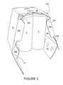
- Figure 3 illustrates securing panels 24a, 24b being folded inwardly, whilst top end flaps 32a, 32b are folded downwardly. Gusset panels 30a, 30b are being folded between top end flaps 32a, 32b and securing panels 24a, 24b.
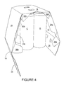
- Figure 4 illustrates securing panels 24a, 24b being folded between one of the respective opposed side walls 12, 16 to which it is hinged and an article adjacent that respective opposed side walls 12, 16.
- Top end flaps 32a and 32b have been folded substantially perpendicularly with the top panel 14 whereby preventing dislodgement of the article from the top of the carton 90.
- end closure panels 26a, 26b remain substantially perpendicular to opposed side walls 12, 16 whereas securing panels 24a, 24b are folded substantially 180° about fold line 25a, 25b such that they are in flat face contacting relationship with a respective one of opposed side wall panels 12, 16.
- the end closure panels 26a, 26b only partially close the end of the carton 90.
- the end closure panels 26a, 26b only partially extend between the opposing side walls 12, 16.
- bottom end flap 36 has been secured to each of end closure panels 26a, 26b.
- this securing will be achieved using adhesive.
- the adhesive is applied to an inside surface of the bottom end flap 36 in an inline gluing process either manually or automatically however, in alternative embodiments it is envisaged that the adhesive could be applied to an outer surface of each of the end closure panels 26a, 26b. In an alternative embodiment it is envisaged that a mechanical locking means could be used in addition or alternative to adhesive.
- the end flap 36 only partially overlaps with the end closure panels 26a, 26b.
- the end flap 36 together with the end closure panels 26a, 26b extend between the opposing side walls 12, 16.
- the arrangement of the web panel 34a, 34b and the end closure panel 26a, 26b allow the carton to closely or tightly engage the articles C therein by folding about the curvature of the articles C.
- Figure 6 illustrates a blank 110 according to a second embodiment of the present invention, where like parts have been designated by the same reference numeral with the prefix "1" and only the differences are described in any greater detail.
- Blank 110 comprises end closure structures 122a, 122b, in which web panels 134a, 134b are defined by a "V" shaped fold line 133a, 133b the ends of which form a vertex with one of fold lines 129a, 129b, 131a, 131b respectively.
- a further fold line 137a, 137b extends perpendicularly to fold line 125a, 125b.
- End closure panels 126a, 126b comprise an upper portion 170a, 170b defined in part by fold line 137a, 137b and "V" shaped fold line 133a, 133b.
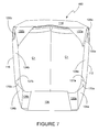
- Figure 7 illustrates that the arrangement of web panels 134a, 134b allows the securing panel 124a, 124b to be folded into flat face contacting relationship with a respective opposed side wall 112, 116 whilst end closure panels 126a, 126b are substantially perpendicular to the respective opposed side walls 112, 116.
- upper portions 170a, 170b are disposed at an inclined relationship to a notional horizontal plane, in a similar manner to that of a lower region of securing panel 124a, 124b of the first embodiment.
- Fold line 137a, 137b facilitates the folding of the upper portion 170a, 170b.
- FIG 8 there is shown a blank according to a third embodiment of the present invention in which like parts have been designated with the same reference numeral with the prefix "2" and only the differences are described in detail.
- FIG. 8 there is shown a blank 410 according to a third embodiment of the present invention, the third embodiment is similar in structure to the previous embodiments, like parts are denoted with the same reference sign with the prefix "4", only differences will be described in any detail.
- Blank 410 is sized and arranged to accommodate articles C arranged in an array size of 1x2 whereas the embodiments of Figures 1 to 7 are sized and arranged to accommodate articles arranged in an array size of 2x2.
- Gusset panel 434a, 434b is defined in part by a hinge line 427a, 427b which couples it to sidewall 412, 416 respectively, which hinge line is defined by a series of spaced apart cut lines or partial cut lines. Gusset panel 434a, 434b is also defined in part by a first pair of co-linear cut lines 433a, 433b and in part by a second pair of co-linear cut lines 437a, 437b.
- An additional cut line 439a, 439b is provided which together with the second pair of cut lines 437a, 437b define a tab 470a, 470b disposed between the gusset panel 434a, 434b and anchoring panel 424a, 424b.
- the base panel 420 comprises a first part 480 of a mechanical lock which together with a second part 482 of the locking mechanism provided in the base panel 418 secures the base panels 420 and 418 in an at least partially overlapping configuration.
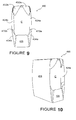
- Figure 9 and 10 illustrate the blank of Figure 8 assembled into a carton 490 about a group of articles C.
- the tab 470a, 470b facilitates folding of the anchoring panel 424a, 424b between the article A and the respective side wall 412, 416.
- FIG. 11 there is shown a blank 510 according to a fourth embodiment of the present invention, the fourth embodiment is similar in structure to the previous embodiments, like parts are denoted with the same reference sign with the prefix "5", only differences will be described in any detail.
- Blank 510 is sized and arranged to accommodate articles arranged in an array size of 1x3.
- FIG. 12 there is shown a blank 610 according to a fifth embodiment of the present invention, the fifth embodiment is similar in structure to the previous embodiment, like parts are denoted with the same reference sign with the prefix "6", only differences will be described in any detail.
- Blank 610 is sized and arranged to accommodate articles arranged in an array size of 2x3.
- Blank 610 comprises a wing panel 672a, 672b coupled to each of the anchoring panels 624a, 624b respectively.
- the wing panel 672a, 672b extends the reach of the anchoring panel 624a, 624b, enhancing the security of the carton.
- the wing panel 672a, 672b is dimensioned smaller than the anchoring panels 624a, 624b.
- the wing panel 672a, 672b is tapered such that it is narrowest at it outermost edge 673a, 673b this facilitates easier insertion of the anchoring panel 624a, 624b between the respective side wall 612, 616 and an adjacent article C.
- FIG. 13 there is shown a blank 710 according to a sixth embodiment of the present invention, the sixth embodiment is similar in structure to the previous embodiments, like parts are denoted with the same reference sign with the prefix "7", only differences will be described in any detail.
- Blank 710 comprises a unitary base panel 718 which is coupled on opposing sides to side wall panels 712, 716.
- the blank comprises a composite top panel having a first top panel 714 and a second top panel 720 an outer surface of which is secured to an inner surface of first top panel 714.
- First top end closure panel 732a is hingedly connected to first top panel 714 whereas second top end closure panel 732b is coupled to second top panel 720.
- the inner surface of second top panel 720 may be secured to an outer surface of first top panel 714.
- FIG. 14 there is shown a blank 810 according to seventh embodiment of the present invention, the seventh embodiment is similar in structure to the previous embodiments, like parts are denoted with the same reference sign with the prefix "8", only differences will be described in any detail.
- First top end closure panel 832a extends between the free edge of the first top panel 814 and the hinged connection to the second side wall panel 816. It is envisaged that a portion of the first top end closure panel 832a may be secured to a portion of second top end closure panel 832b either to an internal or external surface thereof.
- hinged or foldable connections should not be construed as necessarily referring to a single fold line only, indeed it is envisaged that hinged connection can be formed from one or more of the following, a score line, a frangible line or a fold line, without departing from the scope of the invention.
Landscapes
- Engineering & Computer Science (AREA)
- Mechanical Engineering (AREA)
- Cartons (AREA)
- Packages (AREA)
Abstract
Description
- The present invention relates to a carton and blank for forming the same. More specifically but not exclusively to a carton having a substantially tubular structure, said carton being of the wraparound type and optionally having means for automatically folding an end panel so as to at least partially close an end of the tubular structure.
- Wraparound type carton blanks typically comprise plurality of panels foldably hinged to each other for forming top, base and side walls. It is also known to provide an end closure structure of at least partially closing the end of the wraparound carton such a carton is shown in
EP 0446042 to Bakx . - It is desirable to increase the security of the articles within the carton to prevent theft of the articles from the carton. It is also desirable to provide means for carrying a package.
- According to a first aspect of the invention there is provided a carton for packaging a plurality of articles such as bottles or cans, which carton comprises top and bottom panels connected together by spaced side wall panels thereby forming a tubular structure and a set of end panels at each end of the tubular structure for at least partially closing that end of the tubular structure, each set of said end panels comprising a pair of lower end closure panels connected to the side wall panels respectively to at least partially close a lower part of the respective end, each of said lower end closure panels being hingedly interconnected by a gusset panel to an anchoring panel hinged to an adjacent one of the side wall panels by a first hinged connection, said anchoring panel extends sufficiently internally of the tubular structure to permit the anchoring panel to be tucked between the adjacent side wall panel and an adjacent article to retain said each lower end closure panel in a closed position wherein one of said gusset panels is hinged to an adjacent one of the side wall panels by a hinge line.
- Preferably, said one gusset panel is directly hinged to said adjacent one of the side wall panels.
- Preferably, the carton further comprises a bottom end flap hinged to said bottom panel and secured to respective outside surfaces of the lower end closure panels.
- Preferably, said first hinged connections each comprise a fold line, and said hinge line is disposed co-linear with an adjacent one of said fold lines.
- Preferably, said one gusset panel is triangular in shape.
- Preferably, the bottom end flap only partially overlaps with the lower end closure panels.
- Preferably, the bottom end flap only partially extends between the spaced side wall panels.
- Preferably, the bottom end flap together with the lower end closure panels fully extend between spaced side wall panels.
- According to a second aspect of the invention there is provided a carton blank for forming a carton for packaging a plurality of articles such as bottles or cans, which blank comprises top and bottom panels connected together by spaced side wall panels whereby forming a tubular structure in a setup carton and a set of end panels for at least partially closing that end of the tubular structure, each set of said end panels comprising a pair of lower end closure panels connected to the side wall panels respectively to at least partially close a lower part of the respective end, each of said lower end closure panels being hingedly interconnected by a gusset panel to an anchoring panel hinged to an adjacent one of the side wall panels by a fold line, said anchoring panel extends sufficiently internally of the tubular structure to permit said anchoring panel to be tucked between the adjacent side wall panel and an adjacent article wherein one of said gusset panels is hinged to an adjacent one of the side wall panels by a hinge line.
- Preferably, said one gusset panel is directly hinged to said adjacent one of the side wall panels.
- Preferably, the blank further comprises a bottom end flap hinged to said bottom panel and securable to the lower end closure panels.
- Preferably, said hinge line is disposed co-linear with an adjacent one of said fold lines.
- Preferably, the bottom end flap is spaced and separated from the lower end closure panels.
- Preferably, the bottom end flap only partially extends between the lower end closure panels.
- Exemplary embodiments of the invention will now be described with reference to the accompanying drawings in which:
-
FIGURE 1 shows a plan view of a blank for forming a carton according to a first embodiment of the present invention, -
FIGURE 2 illustrates a perspective view of the blank ofFigure 1 partially assembled about a group of articles, -
FIGURE 3 illustrates a perspective view of a further stage of assembly of the blank ofFigure 1 about a group of articles, -
FIGURE 4 illustrates a perspective view of a still further stage of assembly of the blank ofFigure 1 about a group of articles, -
FIGURE 5 illustrates a perspective view of an assembled carton according to a first embodiment of the present invention, -
FIGURE 6 shows a plan view of a blank for forming a carton according to a second embodiment of the present invention, -
FIGURE 7 illustrates a perspective view of an assembled carton according to a second embodiment of the present invention, -
FIGURE 8 shows a plan view of a blank for forming a carton according to a third embodiment of the present invention, -
FIGURE 9 illustrates a perspective view of an assembled carton according to a third embodiment of the present invention, -
FIGURE 10 illustrates a perspective view of an assembled carton according to a third embodiment of the present invention, -
FIGURE 11 shows a plan view of a blank for forming a carton according to a fourth embodiment of the present invention, -
FIGURE 12 shows a plan view of a blank for forming a carton according to a fifth embodiment of the present invention, -
FIGURE 13 shows a plan view of a blank for forming a carton according to a sixth embodiment of the present invention, and -
FIGURE 14 shows a plan view of a blank for forming a carton according to a seventh embodiment of the present invention. -
Figure 1 shows a blank 10 for forming a carton 70 which blank 10 comprises a plurality ofpanels base wall 18, 20 a pair ofopposed side walls top wall 14. - The plurality of
panels top wall 14, opposedside walls base wall -
Panels composite base wall -
Panels apertures 6 which comprise a point P. Theapertures 6 can be engaged either manual or automatically to facilitate securing the carton and for tightening the carton about a group of articles A. - Each
opposed side wall end closure structures End closure structures end closure structures - Each
end closure structure anchoring panel opposed side walls fold lines top end flap top panel 14 alongfold lines top end flaps gusset panels fold lines Gusset panels panels fold lines Gusset panels top end flaps panels -
Apertures top panel 14, a respective one ofopposed side panels top end flaps 32b gusset panels panels Apertures end closure structures - Web panels or
gusset panels panel fold lines -
Web panels opposed side panels fold lines Fold lines fold lines cut lines 27a, 27b respectively.Web panels cut lines Cut lines web panels end closure panels end closure panels web panels web panels end closure panels Web panels sidewall end closure panel panels embodiment web panels -
Top panel 14 comprises a handle havingfinger engaging portions 50. Fingerengaging portions 50 comprise acut line 54 which is arcuate in nature. Each end ofcutline 54 is adjacent to afold line 58, hingedly connected therebetween.Cutline 54 and foldline 58 define aflap panel 52.Flap panel 52 is displaceable from a plane defined bytop panel 14.Flap panel 52 comprises a pair of arcuate cut lines 56 disposed about an edge ofcutline 54 substantially opposingfold line 58. Cutlines 56 and cutline 54 define in part a pair oftabs 55.Tabs 55 facilitate displacement of flap panels 53 into the assembled carton, by deflecting that of the plane offlap panel 52 alternatively whentabs 55 are forced past articles A. Abottom end flap 36 is hinged tobottom panel 18 alongfold line 35, in the preferred embodiment it is envisaged that a single end flap will be provided for each end of the carton.Bottom end flap 36 is spaced from and separated fromend closure panel 26b, 26d by a cut out or recess. Additionally thebase panels fold lines 17 and 11 which hingebase panels side panels top panel 14 is tapered at opposing sides proximate hingedconnections side panels -
Figures 2 to 5 illustrate assembly of the blank 10 into acarton 90.Figure 2 illustrates blank 10, partially folded about a group of articlesA. Top panel 14 is placed upon the group of articles A.Opposed side walls fold lines -
Figure 3 illustrates securingpanels top end flaps Gusset panels top end flaps panels -
Figure 4 illustrates securingpanels opposed side walls opposed side walls - In this way the article A anchors or retains the
respective securing panel top panel 14 whereby preventing dislodgement of the article from the top of thecarton 90. - Furthermore, by virtue of the provision of
web panels fold lines lines end closure panels opposed side walls panels fold line side wall panels end closure panels carton 90. Theend closure panels side walls - Turning now to
Figure 5 , it can be seen thatbottom end flap 36 has been secured to each ofend closure panels bottom end flap 36 in an inline gluing process either manually or automatically however, in alternative embodiments it is envisaged that the adhesive could be applied to an outer surface of each of theend closure panels end flap 36 only partially overlaps with theend closure panels end flap 36 together with theend closure panels side walls web panel end closure panel -
Figure 6 illustrates a blank 110 according to a second embodiment of the present invention, where like parts have been designated by the same reference numeral with the prefix "1" and only the differences are described in any greater detail. -
Blank 110 comprisesend closure structures web panels fold line fold lines further fold line line -
End closure panels upper portion fold line fold line -
Figure 7 illustrates that the arrangement ofweb panels panel opposed side wall end closure panels opposed side walls - It can be seen in
Figure 7 thatupper portions panel line upper portion - Turning now to
Figure 8 , there is shown a blank according to a third embodiment of the present invention in which like parts have been designated with the same reference numeral with the prefix "2" and only the differences are described in detail. - Turning now to
Figure 8 there is shown a blank 410 according to a third embodiment of the present invention, the third embodiment is similar in structure to the previous embodiments, like parts are denoted with the same reference sign with the prefix "4", only differences will be described in any detail. -
Blank 410 is sized and arranged to accommodate articles C arranged in an array size of 1x2 whereas the embodiments ofFigures 1 to 7 are sized and arranged to accommodate articles arranged in an array size of 2x2. -
Gusset panel hinge line Gusset panel co-linear cut lines co-linear cut lines - An
additional cut line cut lines tab gusset panel panel - The
base panel 420 comprises afirst part 480 of a mechanical lock which together with asecond part 482 of the locking mechanism provided in thebase panel 418 secures thebase panels -
Figure 9 and 10 illustrate the blank ofFigure 8 assembled into acarton 490 about a group of articles C. Thetab anchoring panel respective side wall - Turning now to
Figure 11 there is shown a blank 510 according to a fourth embodiment of the present invention, the fourth embodiment is similar in structure to the previous embodiments, like parts are denoted with the same reference sign with the prefix "5", only differences will be described in any detail. -
Blank 510 is sized and arranged to accommodate articles arranged in an array size of 1x3. - Turning now to
Figure 12 there is shown a blank 610 according to a fifth embodiment of the present invention, the fifth embodiment is similar in structure to the previous embodiment, like parts are denoted with the same reference sign with the prefix "6", only differences will be described in any detail. -
Blank 610 is sized and arranged to accommodate articles arranged in an array size of 2x3. -
Blank 610 comprises awing panel panels wing panel anchoring panel wing panel panels wing panel outermost edge anchoring panel respective side wall - Turning now to
Figure 13 there is shown a blank 710 according to a sixth embodiment of the present invention, the sixth embodiment is similar in structure to the previous embodiments, like parts are denoted with the same reference sign with the prefix "7", only differences will be described in any detail. -
Blank 710 comprises aunitary base panel 718 which is coupled on opposing sides toside wall panels top panel 714 and a secondtop panel 720 an outer surface of which is secured to an inner surface of firsttop panel 714. First topend closure panel 732a is hingedly connected to firsttop panel 714 whereas second topend closure panel 732b is coupled to secondtop panel 720. Alternatively, the inner surface of secondtop panel 720 may be secured to an outer surface of firsttop panel 714. - Turning now to
Figure 14 there is shown a blank 810 according to seventh embodiment of the present invention, the seventh embodiment is similar in structure to the previous embodiments, like parts are denoted with the same reference sign with the prefix "8", only differences will be described in any detail. - First top
end closure panel 832a extends between the free edge of the firsttop panel 814 and the hinged connection to the secondside wall panel 816. It is envisaged that a portion of the first topend closure panel 832a may be secured to a portion of second topend closure panel 832b either to an internal or external surface thereof. - It is envisaged that modification may be made in the foregoing without departing from the scope of the invention.
- It should be appreciated that as used herein, directive references such as "top", "bottom", "end", "side", "upper" and "lower" do not limit the respective panels to such orientation, but merely serve to distinguish these panels from one another. It should be further appreciated that any reference to hinged or foldable connections should not be construed as necessarily referring to a single fold line only, indeed it is envisaged that hinged connection can be formed from one or more of the following, a score line, a frangible line or a fold line, without departing from the scope of the invention.
Claims (12)
- A carton (190; 490) for packaging a plurality of articles (C) such as bottles or cans, which carton (190; 490) comprises top (114; 414; 514; 614; 714; 814) and bottom (118, 120: 418, 420; 518, 520; 618, 620; 718, 720; 818, 820) panels connected together by spaced side wall panels (112, 116; 412, 416; 512, 516; 612, 616; 712, 716; 812, 816) thereby forming a tubular structure and a set of end panels (122a, 122b, 122c, 122d; 422a, 422b; 422c, 422d; 522a,522b,522c,522d;622a,622b,622c,622d;722a,722b,722c,722d;822a,822b,822c, 822d) at each end of the tubular structure for at least partially closing that end of the tubular structure, each set of said end panels comprising a pair of lower end closure panels connected to the side wall panels respectively to at least partially close a lower part of the respective end, lower portions of each of said lower end closure panels (126a, 126b; 426a, 426b; 526a, 526b; 626a, 626b; 726a, 726b; 826a, 826b) being hingedly interconnected in part by a web panel (134a, 134b; 434a, 434b; 534a, 534b; 634a, 634b; 734a, 734b; 834a, 834b) and in part by an upper portion of the lower end closure panel (126a, 126b; 426a, 426b; 526a, 526b; 626a, 626b; 726a, 726b; 826a, 826b) or a tab (470a, 470b) to an anchoring panel (124a, 124b; 424a, 424b; 524a, 524b; 624a, 624b; 724a, 724b, 824a, 824b) hinged to an adjacent one of the side wall panels (112, 116; 412, 416; 512, 516; 612, 616; 712, 716; 812, 816) by a first hinged connection (125a, 125b; 425a, 425b; 525a, 525b; 625a, 625b; 725a, 725b; 825a, 825b), said anchoring panel (124a, 124b; 424a, 424b; 524a, 524b; 624a, 624b; 724a, 724b, 824a, 824b) extends sufficiently internally of the tubular structure to permit the anchoring panel (124a, 124b; 424a, 424b; 524a, 524b; 624a, 624b; 724a, 724b, 824a, 824b) to be tucked between the adjacent side wall panel (112, 116; 412, 416; 512, 516; 612, 616; 712, 716; 812, 816) and an adjacent article (C) to retain said each lower end closure panel (126a, 126b; 426a, 426b; 526a, 526b; 626a, 626b; 726a, 726b; 826a, 826b) in a closed position wherein one of said web panels (134a, 134b; 434a, 434b; 534a, 534b; 634a, 634b; 734a, 734b; 834a, 834b) is hinged to an adjacent one of the side wall panels (112, 116; 412, 416; 512, 516; 612, 616; 712, 716; 812, 816) by a hinge line (127a, 127b; 427a, 427b; 527a, 527b; 627a, 627b; 727a, 727b; 827a, 827b) characterised in that said one web panel (134a, 134b; 434a, 434b; 534a, 534b; 634a, 634b; 734a, 734b; 834a, 834b) is directly hinged to said adjacent one of the side wall panels (112,116; 412, 416; 512,516;612,616;712,716;812,816).
- A carton according to claim 1 wherein each set of said end panels further comprises a bottom end flap (136; 436; 536; 736; 836) hinged to said bottom panel (118, 120: 418, 420; 518, 520; 618, 620; 718, 720; 818, 820) and secured to respective outside surfaces of the adjacent lower end closure panels.
- A carton according to either one of claims 1 or 2 wherein said first hinged connections (125a, 125b; 425a, 425b; 525a, 525b; 625a, 625b; 725a, 725b; 825a, 825b) between each of said anchoring panels and the adjacent side wall panel comprises a fold line, which fold line is disposed co-linear with said hinge line.
- A carton according to any one of claims 1 to 3 wherein said one web panel (134a, 134b; 434a, 434b; 534a, 534b; 634a, 634b; 734a, 734b; 834a, 834b) is triangular in shape.
- A carton according to claim 2 wherein the bottom end flap (136; 436; 536; 736; 836) only partially overlaps with the lower end closure panels (126a, 126b; 426a, 426b; 526a, 526b; 626a, 626b; 726a, 726b; 826a, 826b).
- A carton according to claim 2 or 5 wherein the bottom end flap (136; 436; 536; 736; 836) only partially extends between the side wall panels (112, 116; 412, 416; 512, 516; 612, 616; 712, 716; 812, 816).
- A carton according to claims 2, 5 or 6 wherein the bottom end flap (136; 436; 536; 736; 836) together with the lower end closure panels (126a, 126b; 426a, 426b; 526a, 526b; 626a, 626b; 726a, 726b; 826a, 826b) fully extend between the side wall panels (112, 116; 412, 416;512,516;612,616;712,716;812,816).
- A blank (110; 410; 510; 610; 710; 810) for forming a carton (190; 490) for packaging a plurality of articles (C) such as bottles or cans, which blank (110; 410; 510; 610; 710; 810) comprises top (114; 414; 514; 614; 714; 814) and bottom (118, 120: 418, 420; 518, 520; 618, 620; 718, 720; 818, 820) panels connected together by spaced side wall panels (112, 116; 412, 416; 512, 516; 612, 616; 712, 716; 812, 816) thereby forming a tubular structure and a set of end panels (122a, 122b, 122c, 122d; 422a, 422b; 422c, 422d; 522a, 522b, 522c, 522d; 622a, 622b, 622c, 622d; 722a, 722b, 722c, 722d; 822a, 822b, 822c, 822d) at each end of the tubular structure for at least partially closing that end of the tubular structure, each set of said end panels comprising a pair of lower end closure panels connected to the side wall panels respectively to at least partially close a lower part of the respective end, lower portions of each of said lower end closure panels (126a, 126b; 426a, 426b; 526a, 526b; 626a, 626b; 726a, 726b; 826a, 826b) being hingedly interconnected in part by a web panel (134a, 134b; 434a, 434b; 534a, 534b; 634a, 634b; 734a, 734b; 834a, 834b) and in part by an upper portion of the lower end closure panel (126a, 126b; 426a, 426b; 526a, 526b; 626a, 626b; 726a, 726b; 826a, 826b) or a tab (470a, 470b) to an anchoring panel (124a, 124b; 424a, 424b; 524a, 524b; 624a, 624b; 724a, 724b, 824a, 824b) hinged to an adjacent one of the side wall panels (112, 116; 412, 416; 512, 516; 612, 616; 712, 716; 812, 816) by a first hinged connection (125a, 125b; 425a, 425b; 525a, 525b; 625a, 625b; 725a, 725b; 825a, 825b), said anchoring panel (124a, 124b; 424a, 424b; 524a, 524b; 624a, 624b; 724a, 724b, 824a, 824b) extends sufficiently internally of the tubular structure to permit the anchoring panel (124a, 124b; 424a, 424b; 524a, 524b; 624a, 624b; 724a, 724b, 824a, 824b) to be tucked between the adjacent side wall panel (112, 116; 412, 416; 512, 516; 612, 616; 712, 716; 812, 816) and an adjacent article (C) to retain said each lower end closure panel (126a, 126b; 426a, 426b; 526a, 526b; 626a, 626b; 726a, 726b; 826a, 826b) in a closed position wherein one of said web panels (134a, 134b; 434a, 434b; 534a, 534b; 634a, 634b; 734a, 734b; 834a, 834b) is hinged to an adjacent one of the side wall panels (112, 116; 412, 416; 512, 516; 612, 616; 712, 716; 812, 816) by a hinge line (127a, 127b; 427a, 427b; 527a, 527b; 627a, 627b; 727a, 727b; 827a, 827b) characterised in that said one web panel (134a, 134b; 434a, 434b; 534a, 534b; 634a, 634b; 734a, 734b; 834a, 834b) is directly hinged to said adjacent one of the side wall panels (112,116; 412, 416; 512, 516; 612, 616; 712, 716; 812, 816).
- A blank according to claim 8 wherein each set of said end panels further comprises a bottom end flap (136; 436; 536; 736; 836) hinged to said bottom panel (118, 120: 418, 420; 518, 520; 618, 620; 718, 720; 818, 820) and securable to the adjacent lower end closure panels (126a, 126b; 426a, 426b; 526a, 526b; 626a, 626b; 726a, 726b; 826a, 826b).
- A blank according to either of claims 8 or 9 wherein said hinge line (127a, 127b; 427a, 427b; 527a, 527b; 627a, 627b; 727a, 727b; 827a, 827b) is disposed co-linear with an fold line (125a, 125b; 425a, 425b; 525a, 525b; 625a, 625b; 725a, 725b; 825a, 825b).
- A blank according to claim 8 wherein the bottom end flap (136; 436; 536; 736; 836) is spaced and separated from the adjacent lower end closure panels (126a, 126b; 426a, 426b; 526a, 526b; 626a, 626b; 726a, 726b; 826a, 826b).
- A blank according to claim 8 or 10 wherein the bottom end flap (136; 436; 536; 736; 836) only partially extends between the adjacent lower end closure panels (126a, 126b; 426a, 426b; 526a, 526b; 626a, 626b; 726a, 726b; 826a, 826b).
Applications Claiming Priority (2)
| Application Number | Priority Date | Filing Date | Title |
|---|---|---|---|
| GBGB0722410.8A GB0722410D0 (en) | 2007-11-15 | 2007-11-15 | Carton and carton blank |
| EP08850721A EP2207730B1 (en) | 2007-11-15 | 2008-11-14 | Carton and carton blank |
Related Parent Applications (1)
| Application Number | Title | Priority Date | Filing Date |
|---|---|---|---|
| EP08850721.5 Division | 2008-11-14 |
Publications (1)
| Publication Number | Publication Date |
|---|---|
| EP2520511A1 true EP2520511A1 (en) | 2012-11-07 |
Family
ID=38896341
Family Applications (2)
| Application Number | Title | Priority Date | Filing Date |
|---|---|---|---|
| EP12179205A Withdrawn EP2520511A1 (en) | 2007-11-15 | 2008-11-14 | Carton and carton blank |
| EP08850721A Active EP2207730B1 (en) | 2007-11-15 | 2008-11-14 | Carton and carton blank |
Family Applications After (1)
| Application Number | Title | Priority Date | Filing Date |
|---|---|---|---|
| EP08850721A Active EP2207730B1 (en) | 2007-11-15 | 2008-11-14 | Carton and carton blank |
Country Status (5)
| Country | Link |
|---|---|
| US (1) | US8496162B2 (en) |
| EP (2) | EP2520511A1 (en) |
| CL (1) | CL2008003417A1 (en) |
| GB (1) | GB0722410D0 (en) |
| WO (1) | WO2009064976A1 (en) |
Families Citing this family (11)
| Publication number | Priority date | Publication date | Assignee | Title |
|---|---|---|---|---|
| BR112013028448B1 (en) | 2011-05-06 | 2020-07-21 | Graphic Packaging International, Llc | method of forming a cardboard box |
| ES2567472T3 (en) | 2011-10-19 | 2016-04-22 | Graphic Packaging International, Inc. | System and procedure to activate the protection features of the items in a cardboard box |
| JP3179070U (en) * | 2012-08-02 | 2012-10-11 | ミードウエストベコ パッケージングシステムズ エル・エル・シー | Carton blank and carton |
| US9840358B2 (en) * | 2013-03-14 | 2017-12-12 | Graphic Packaging International, Inc. | Carton with article protection feature |
| US9701436B2 (en) | 2013-04-10 | 2017-07-11 | Graphic Packaging International, Inc. | Carton with article protection feature |
| BR112015025302B1 (en) | 2013-04-10 | 2022-06-07 | Graphic Packaging International, Llc | Package for housing at least one article, die for forming a package for housing at least one article, package for housing at least one article, matrix for forming a package, and method for forming a package |
| WO2016123325A1 (en) * | 2015-01-29 | 2016-08-04 | Westrock Packaging Systems, Llc | Paperboard carton and carton blank |
| AU2020268204B2 (en) | 2019-05-03 | 2026-04-23 | Westrock Packaging Systems, Llc | Article carrier and blank therefor |
| WO2020231722A1 (en) * | 2019-05-10 | 2020-11-19 | Westrock Packaging Systems, Llc | Article carrier, blank therefor and method of packaging |
| USD980069S1 (en) | 2020-07-14 | 2023-03-07 | Ball Corporation | Metallic dispensing lid |
| US12168551B2 (en) | 2021-03-01 | 2024-12-17 | Ball Corporation | Metal container and end closure with seal |
Citations (4)
| Publication number | Priority date | Publication date | Assignee | Title |
|---|---|---|---|---|
| EP0446042A1 (en) | 1990-03-08 | 1991-09-11 | The Mead Corporation | Wrap around carton with end closure panels |
| EP0520411A1 (en) * | 1991-06-28 | 1992-12-30 | 4P Nicolaus Kempten GmbH | Wrap-around sleeve for a group of objects such as primary containers |
| US20060191811A1 (en) * | 2005-02-28 | 2006-08-31 | Fogle James C | Wrap-around carton with dispensing feature |
| US20070241017A1 (en) * | 2006-04-17 | 2007-10-18 | Sutherland Robert L | Carrier Packages and Methods of Erecting Carrier Packages |
Family Cites Families (11)
| Publication number | Priority date | Publication date | Assignee | Title |
|---|---|---|---|---|
| US3203584A (en) * | 1962-09-05 | 1965-08-31 | Mead Corp | Article carrier |
| US3204814A (en) * | 1964-07-22 | 1965-09-07 | Container Corp | Bottle carrier with partition |
| US4022372A (en) * | 1976-08-05 | 1977-05-10 | Olinkraft, Inc. | Article carrier |
| EP0044169B1 (en) | 1980-07-11 | 1985-11-06 | The Mead Corporation | Carton for beverage containers |
| US4747487A (en) * | 1987-09-29 | 1988-05-31 | The Mead Corporation | End loaded carton |
| US4910266A (en) * | 1987-10-15 | 1990-03-20 | The Goodyear Tire & Rubber Company | Modification process using N-chloro-thiosulfonamide and rubber |
| US4919266A (en) | 1989-06-09 | 1990-04-24 | The C. W. Zumbiel Co. | Carton with end wall display window |
| US5328030A (en) | 1993-04-08 | 1994-07-12 | Riverwood International Corporation | Sleeve-type carrier |
| US5542536A (en) | 1995-05-11 | 1996-08-06 | Riverwood International Corporation | Wrap-around carrier with bar code blocking end panel |
| EP1912870B1 (en) * | 2005-07-22 | 2010-05-05 | Graphic Packaging International, Inc. | Wrap-around carrier and blank |
| GB0722417D0 (en) * | 2007-11-15 | 2007-12-27 | Meadwestvaco Packaging Systems | Carton and carton blank |
-
2007
- 2007-11-15 GB GBGB0722410.8A patent/GB0722410D0/en not_active Ceased
-
2008
- 2008-11-14 US US12/743,174 patent/US8496162B2/en not_active Expired - Fee Related
- 2008-11-14 EP EP12179205A patent/EP2520511A1/en not_active Withdrawn
- 2008-11-14 WO PCT/US2008/083544 patent/WO2009064976A1/en not_active Ceased
- 2008-11-14 EP EP08850721A patent/EP2207730B1/en active Active
- 2008-11-17 CL CL2008003417A patent/CL2008003417A1/en unknown
Patent Citations (4)
| Publication number | Priority date | Publication date | Assignee | Title |
|---|---|---|---|---|
| EP0446042A1 (en) | 1990-03-08 | 1991-09-11 | The Mead Corporation | Wrap around carton with end closure panels |
| EP0520411A1 (en) * | 1991-06-28 | 1992-12-30 | 4P Nicolaus Kempten GmbH | Wrap-around sleeve for a group of objects such as primary containers |
| US20060191811A1 (en) * | 2005-02-28 | 2006-08-31 | Fogle James C | Wrap-around carton with dispensing feature |
| US20070241017A1 (en) * | 2006-04-17 | 2007-10-18 | Sutherland Robert L | Carrier Packages and Methods of Erecting Carrier Packages |
Also Published As
| Publication number | Publication date |
|---|---|
| GB0722410D0 (en) | 2007-12-27 |
| HK1145827A1 (en) | 2011-05-06 |
| US8496162B2 (en) | 2013-07-30 |
| WO2009064976A1 (en) | 2009-05-22 |
| CL2008003417A1 (en) | 2009-10-16 |
| EP2207730B1 (en) | 2013-01-02 |
| US20110132979A1 (en) | 2011-06-09 |
| EP2207730A1 (en) | 2010-07-21 |
Similar Documents
| Publication | Publication Date | Title |
|---|---|---|
| EP2207730B1 (en) | Carton and carton blank | |
| AU751070B2 (en) | Handle arrangement for a carton | |
| US6536656B2 (en) | Carton and a handle therefor | |
| AU729299B2 (en) | Carton and a handle therefor | |
| EP1381545B1 (en) | Carton with transverse strap handle | |
| US5996883A (en) | Carton and a handle therefor | |
| US8708217B2 (en) | Carton and carton blank | |
| US20040262374A1 (en) | Beverage carton with strap type carrying handle | |
| US6942140B2 (en) | Carton with handle and blank thereof | |
| AU2001255628A1 (en) | Carton with transverse strap handle | |
| AU774179B2 (en) | Carton and a handle therefor | |
| EP1331171A1 (en) | Beverage carton with strap type carrying handle | |
| JP2004510656A (en) | Carton closing mechanism | |
| JP3734038B2 (en) | Carton with handle and blank for such carton | |
| HK1145827B (en) | Carton and carton blank | |
| US20060065555A1 (en) | Bottle carrier | |
| ZA200309132B (en) | Carton with transverse strap handle. |
Legal Events
| Date | Code | Title | Description |
|---|---|---|---|
| PUAI | Public reference made under article 153(3) epc to a published international application that has entered the european phase |
Free format text: ORIGINAL CODE: 0009012 |
|
| 17P | Request for examination filed |
Effective date: 20120803 |
|
| AC | Divisional application: reference to earlier application |
Ref document number: 2207730 Country of ref document: EP Kind code of ref document: P |
|
| AK | Designated contracting states |
Kind code of ref document: A1 Designated state(s): AT BE BG CH CY CZ DE DK EE ES FI FR GB GR HR HU IE IS IT LI LT LU LV MC MT NL NO PL PT RO SE SI SK TR |
|
| 17Q | First examination report despatched |
Effective date: 20130925 |
|
| STAA | Information on the status of an ep patent application or granted ep patent |
Free format text: STATUS: THE APPLICATION IS DEEMED TO BE WITHDRAWN |
|
| 18D | Application deemed to be withdrawn |
Effective date: 20150602 |