EP2520489A1 - Split blade retention race with inner and outer chamfers - Google Patents
Split blade retention race with inner and outer chamfers Download PDFInfo
- Publication number
- EP2520489A1 EP2520489A1 EP12166092A EP12166092A EP2520489A1 EP 2520489 A1 EP2520489 A1 EP 2520489A1 EP 12166092 A EP12166092 A EP 12166092A EP 12166092 A EP12166092 A EP 12166092A EP 2520489 A1 EP2520489 A1 EP 2520489A1
- Authority
- EP
- European Patent Office
- Prior art keywords
- race
- split
- blade
- blade retention
- split blade
- Prior art date
- Legal status (The legal status is an assumption and is not a legal conclusion. Google has not performed a legal analysis and makes no representation as to the accuracy of the status listed.)
- Granted
Links
Images




Classifications
-
- B—PERFORMING OPERATIONS; TRANSPORTING
- B64—AIRCRAFT; AVIATION; COSMONAUTICS
- B64C—AEROPLANES; HELICOPTERS
- B64C11/00—Propellers, e.g. of ducted type; Features common to propellers and rotors for rotorcraft
- B64C11/02—Hub construction
- B64C11/04—Blade mountings
Definitions
- the subject matter disclosed herein relates generally to the field of a split blade retention race for an aircraft propeller blade.
- a propeller for use in an aircraft includes a central rotating hub having a plurality of blade receiving sockets disposed about the hub.
- the propeller blades each have a shank located at the base of each propeller blade, and each shank is disposed in a respective blade receiving socket.
- the blade receiving sockets and the blade shanks are provided with opposed, separated ball bearing race surfaces, and a plurality of ball bearings are held between the blade receiving socket and the blade shank on the race surfaces, allowing adjustment of the pitch of the blade.
- the ball bearing race on the blade shank may be a separate component, referred to as a blade retention race, that encircles the blade shank.
- the blades are shipped with a one piece blade race.
- one piece races may be replaced by split races at overhaul.
- Such a multisection blade retention race may be referred to as a split blade retention race.
- a blade shank assembly for an aircraft propeller blade includes a blade shank; a split blade retention race encircling the blade shank, the split blade retention race including two splits, wherein the split blade retention race comprises: inner chamfers located between the blade shank and the split blade retention race at each of the two splits; and outer chamfers located adjacent to a race surface of the split blade retention race at each of the two splits; and a plurality of ball bearings located on the race surface of the split blade retention race.
- a split blade retention race for a blade shank assembly for an aircraft propeller blade includes a race surface, the race surface configured to hold a plurality of ball bearings; a split surface, the split surface being configured to be located inside of split separating a first section of the split blade retention race from a second section of the split blade retention race; an inner surface, the inner surface being configured to be located adjacent to a blade shank in the blade shank assembly; an inner chamfer, wherein the inner chamfer is angled back along an interface between the split surface to the inner surface; and an outer chamfer, wherein the outer chamfer is angled back along an interface between the split surface and the race surface.
- FIG. 1 illustrates an embodiment of a blade shank assembly for an aircraft propeller blade including a split blade retention race.
- FIG. 2 illustrates a top view of an embodiment of a split blade retention race.
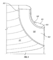
- FIG. 3 illustrates a side view of an embodiment of a blade shank with a split blade retention race at a split.
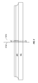
- FIG. 4 illustrates a side view of an embodiment of a split blade retention race.
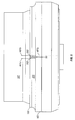
- FIG. 5 illustrates a side view of an embodiment of a split blade retention race on a blade shank.
- FIG. 6 illustrates a detailed view of an embodiment of inner and outer chamfers and associated inner and outer radii.
- FIG. 7 illustrates a detailed view of a compressive deflection of a ball on a race surface.
- Embodiments of a split blade retention race with inner and outer chamfers are provided, with exemplary embodiments being discussed below in detail.
- Current split blade races may have a limited lifespan due to the load from the ball bearings that are held in the race loading the split blade retention race and the geometry of the race at the split.
- Inclusion of chamfers (defined as a straight beveled edge connecting two surfaces) at the split on both the inner surface of the split blade retention race (adjacent to the blade shank) and the outer surface of the split blade retention race (adjacent to the race surface that holds the ball bearings) prevents the ball bearings from loading the unsupported portion at the edge of the split blade retention race at the split.
- a radius connecting the chamfer to the adjacent surface provides a smooth race transition for the ball bearings over the split to prevent damage to the blade shank. This extends the life of the split blade retention race, and reduces the number of propeller blades that need to be scrapped due to damage to the blade shank.
- the chamfers further include associated radii, which are curved surfaces that blend the chamfers to adjacent surfaces on the split blade retention race. The radii provide a smooth transition between the chamfers and the adjacent surfaces.
- FIG. 1 shows an embodiment of a blade shank assembly 100 for insertion into a blade receiving socket (not shown) of an aircraft propeller.
- the blade shank assembly 100 includes blade shank 101, ball bearings 102, and split blade retention races 103.
- Splits 104 are located between sections of split blade retention race 103.
- the edges of split blade race 103 at the splits 104 each include a chamfer on the internal side, adjacent to the shank 101, and on the external side, adjacent to the race surface of the split blade retention races 103 on which ball bearings 102 are located.
- the proportions of the internal and external chamfers ensure that the race is not loaded over the unsupported portion at the edges of the inner split blade retention races 103.
- the internal and external radii provide a smooth transition by ball bearings 102 between the chamfers and the adjacent race surfaces on the split blade retention race 103 in order to prevent damage to the blade shank 101 as the ball bearings 102 pass over the splits 104. This helps to reduce damage to the split blade retention race 103 and the blade shank 101 from the ball bearings as they pass over the splits 104.
- the width of the splits 104 are a resultant of the manufacturing process.
- the split blade retention race 103 is manufactured as a complete ring and then cut in half to form splits 104. Manufacturing the split blade retention race 103 as a complete ring before splitting ensures that the race curvatures of both halves of the split blade retention race 103 are identical.
- FIG. 2 shows a top view of the split blade retention race 103 of FIG. 1 .
- the ball bearings 102 move on the race surface of split blade race 103, and pass over splits 104.
- Splits 104 are located between the sections of split blade retention race 103.
- the split blade retention race 103 includes inner chamfers 201, at the edge of the each of the splits 104 on the inner surface of the split blade retention race 103 that is placed adjacent to blade shank 101.
- the split blade retention race 103 also includes outer chamfers 202, located at the edge of the splits 104 on the race surface of the split blade retention race 103 adjacent to the ball bearings 102.
- the outer chamfers 202 prevent loading from the ball bearings 102 from being transferred to the unsupported section of the split blade retention race 103. Therefore, a ball bearing that is located on a portion of the radius or chamfer where the distance below the race surface equals the compressive deflection of the ball on the race is fully unloaded.
- the split configuration of the split blade retention race 103 is such that only one ball bearing of ball bearings 102 is unloaded at any given time; the rest of the ball bearings 102 share the load. This helps to minimize the amount of load carried by each ball.
- FIG. 3 shows a side view of a blade shank 101 and a split blade retention race 103 at a split 104.
- Race surface 301 is the surface on which the ball bearings 102 are held.
- Split surface 302 of split blade retention race 103 is located inside a split 104 directly facing a corresponding split surface on another section of the split blade retention race 103 on the other side of the split 104.
- Inner chamfer 201 is angled back from split surface 302 to an inner surface of split blade retention race that is adjacent to the blade shank 101.
- a curved inner radius discussed in further detail with respect to FIG.
- Inner chamfer 201 is associated with inner chamfer 201 to provide a smooth blend between the inner chamfer 201 and the surface of the split blade retention race 103 that is adjacent to blade shank 101.
- Outer chamfer 202 is angled back from split surface 302 to race surface 301 such that there is a dip in the race that holds the ball bearings adjacent to the split 104.
- a curved outer radius 303 is associated with outer chamfer 202 to provide a smooth blend between the outer chamfer 202 and the adjacent race surface 301.
- the inner and outer radii ensure that there are no sharp edges between the chamfers 201/202 and adjacent surfaces, as sharp edges tend to cause damage to both the blade shank 101 and race 103.
- FIG. 4 shows a side view of a split blade retention race 103 at a split 104.
- the inner chamfers 201, outer chamfers 202, and race surface 301 are also shown.
- Load lines 401a-b located at the edges of the outer radii associated with outer chamfers 202, show the points at which a ball bearing of ball bearings 102 is fully loaded on the race surface 301 of the split blade retention race 103.
- load lines 401a and 401b the inner chamfers 201, outer chamfers 202, and radii ensure that a ball bearing unloads and becomes fully unloaded over the inner unsupported section of the race.
- the chamfers 201/202 are sized such that only one ball bearing of ball bearings 102 is unloaded at a time, and the outer chamfers 202 are larger than the inner chamfers 201.
- FIG. 5 shows a side view of a blade shank 101 with a split blade retention race 103 at a split 104.
- Inner chamfers 201 and outer chamfers 202 are located on split blade retention race 103 at the edges of the split 104.
- Load lines 401 a-b, located at the edges of the outer radii associated with outer chamfers 202, show the point at which a ball bearing is fully loaded on the race surface 301 of the split blade retention race 103.
- the ball bearing becomes unloaded on either split blade retention race 103 due to the presence of outer chamfers 202 and associated outer radii, preventing loading of the unsupported section of the split blade retention race 103.
- Inner chamfers 201 and associated radii are located on the side of the split blade retention race 103 that is adjacent to the blade shank 101.
- FIG. 6 illustrates a detailed view of an embodiment of inner and outer chamfers and associated inner and outer radii.
- Split blade retention race 103 with race surface 301 and ball bearings 102 located on race surface 301, is shown; the split blade retention race 103 is located on blade shank 101.
- Detailed view 600a shows an inner chamfer 201 and associated inner radius 601.
- Inner chamfer 201 is a straight surface
- inner radius 601 is a curved surface joining the inner chamfer 201 to the surface of split blade retention race 103 that is adjacent to blade shank 101.
- the curve of radius 601 prevents damage to the blade shank 101.
- Detailed view 600b shows an outer chamfer 202 and associated outer radius 303.
- Outer chamfer 202 is a straight surface
- outer radius 303 is a curved surface joining the outer chamfer 202 to the race surface 301, ensuring a smooth transition for the ball bearings 102 as the ball bearings 102 pass over the outer chamfers 202 and outer radii 303.
- Load lines 401a-b are located on the outer edges of the outer radii 303.
- Line 603 illustrates the center load line 603 of a ball bearing 102. When the center load line 603 of a ball bearing 102 is between load lines 401a-b, the ball bearing starts to unload then becomes fully unloaded when the depth below the race surface 301 equals the compressive deflection of the ball bearing 102. This is shown in further detail with respect to FIG.
- the technical effects and benefits of exemplary embodiments include reduction of blade shank damage due to blade race split configuration as well as reduction in wear in the split race edges.
Landscapes
- Engineering & Computer Science (AREA)
- Aviation & Aerospace Engineering (AREA)
- Rolling Contact Bearings (AREA)
Abstract
Description
- The subject matter disclosed herein relates generally to the field of a split blade retention race for an aircraft propeller blade.
- A propeller for use in an aircraft includes a central rotating hub having a plurality of blade receiving sockets disposed about the hub. The propeller blades each have a shank located at the base of each propeller blade, and each shank is disposed in a respective blade receiving socket. The blade receiving sockets and the blade shanks are provided with opposed, separated ball bearing race surfaces, and a plurality of ball bearings are held between the blade receiving socket and the blade shank on the race surfaces, allowing adjustment of the pitch of the blade. The ball bearing race on the blade shank may be a separate component, referred to as a blade retention race, that encircles the blade shank. Currently, the blades are shipped with a one piece blade race.
- Due to the movement and loading of the ball bearings on the race surface, and resulting damage that occurs to the race, one piece races may be replaced by split races at overhaul. Such a multisection blade retention race may be referred to as a split blade retention race. Once the one-piece race is replaced by split races, the movement and loading of the ball bearings on the edges of the split races has a tendency to damage the blade shank beyond repair.
- According to one aspect of the invention, a blade shank assembly for an aircraft propeller blade includes a blade shank; a split blade retention race encircling the blade shank, the split blade retention race including two splits, wherein the split blade retention race comprises: inner chamfers located between the blade shank and the split blade retention race at each of the two splits; and outer chamfers located adjacent to a race surface of the split blade retention race at each of the two splits; and a plurality of ball bearings located on the race surface of the split blade retention race.
- According to another aspect of the invention, a split blade retention race for a blade shank assembly for an aircraft propeller blade includes a race surface, the race surface configured to hold a plurality of ball bearings; a split surface, the split surface being configured to be located inside of split separating a first section of the split blade retention race from a second section of the split blade retention race; an inner surface, the inner surface being configured to be located adjacent to a blade shank in the blade shank assembly; an inner chamfer, wherein the inner chamfer is angled back along an interface between the split surface to the inner surface; and an outer chamfer, wherein the outer chamfer is angled back along an interface between the split surface and the race surface.
- Other aspects, features, and techniques of the invention will become more apparent from the following description taken in conjunction with the drawings.
- Referring now to the drawings wherein like elements are numbered alike in the several FIGURES:
-
FIG. 1 illustrates an embodiment of a blade shank assembly for an aircraft propeller blade including a split blade retention race. -
FIG. 2 illustrates a top view of an embodiment of a split blade retention race. -
FIG. 3 illustrates a side view of an embodiment of a blade shank with a split blade retention race at a split. -
FIG. 4 illustrates a side view of an embodiment of a split blade retention race. -
FIG. 5 illustrates a side view of an embodiment of a split blade retention race on a blade shank. -
FIG. 6 illustrates a detailed view of an embodiment of inner and outer chamfers and associated inner and outer radii. -
FIG. 7 illustrates a detailed view of a compressive deflection of a ball on a race surface. - Embodiments of a split blade retention race with inner and outer chamfers are provided, with exemplary embodiments being discussed below in detail. Current split blade races may have a limited lifespan due to the load from the ball bearings that are held in the race loading the split blade retention race and the geometry of the race at the split. Inclusion of chamfers (defined as a straight beveled edge connecting two surfaces) at the split on both the inner surface of the split blade retention race (adjacent to the blade shank) and the outer surface of the split blade retention race (adjacent to the race surface that holds the ball bearings) prevents the ball bearings from loading the unsupported portion at the edge of the split blade retention race at the split. A radius connecting the chamfer to the adjacent surface provides a smooth race transition for the ball bearings over the split to prevent damage to the blade shank. This extends the life of the split blade retention race, and reduces the number of propeller blades that need to be scrapped due to damage to the blade shank. As noted above, the chamfers further include associated radii, which are curved surfaces that blend the chamfers to adjacent surfaces on the split blade retention race. The radii provide a smooth transition between the chamfers and the adjacent surfaces.
-
FIG. 1 shows an embodiment of ablade shank assembly 100 for insertion into a blade receiving socket (not shown) of an aircraft propeller. Theblade shank assembly 100 includesblade shank 101,ball bearings 102, and splitblade retention races 103.Splits 104 are located between sections of splitblade retention race 103. The edges ofsplit blade race 103 at thesplits 104 each include a chamfer on the internal side, adjacent to theshank 101, and on the external side, adjacent to the race surface of the splitblade retention races 103 on whichball bearings 102 are located. The proportions of the internal and external chamfers ensure that the race is not loaded over the unsupported portion at the edges of the inner splitblade retention races 103. The internal and external radii provide a smooth transition byball bearings 102 between the chamfers and the adjacent race surfaces on the splitblade retention race 103 in order to prevent damage to theblade shank 101 as theball bearings 102 pass over thesplits 104. This helps to reduce damage to the splitblade retention race 103 and theblade shank 101 from the ball bearings as they pass over thesplits 104. The width of thesplits 104 are a resultant of the manufacturing process. The splitblade retention race 103 is manufactured as a complete ring and then cut in half to formsplits 104. Manufacturing the splitblade retention race 103 as a complete ring before splitting ensures that the race curvatures of both halves of the splitblade retention race 103 are identical. -
FIG. 2 shows a top view of the splitblade retention race 103 ofFIG. 1 . Theball bearings 102 move on the race surface ofsplit blade race 103, and pass oversplits 104.Splits 104 are located between the sections of splitblade retention race 103. The splitblade retention race 103 includesinner chamfers 201, at the edge of the each of thesplits 104 on the inner surface of the splitblade retention race 103 that is placed adjacent toblade shank 101. The splitblade retention race 103 also includesouter chamfers 202, located at the edge of thesplits 104 on the race surface of the splitblade retention race 103 adjacent to theball bearings 102. Theouter chamfers 202 prevent loading from theball bearings 102 from being transferred to the unsupported section of the splitblade retention race 103. Therefore, a ball bearing that is located on a portion of the radius or chamfer where the distance below the race surface equals the compressive deflection of the ball on the race is fully unloaded. The split configuration of the splitblade retention race 103 is such that only one ball bearing ofball bearings 102 is unloaded at any given time; the rest of theball bearings 102 share the load. This helps to minimize the amount of load carried by each ball. -
FIG. 3 shows a side view of ablade shank 101 and a splitblade retention race 103 at asplit 104.Race surface 301 is the surface on which theball bearings 102 are held.Split surface 302 of splitblade retention race 103 is located inside asplit 104 directly facing a corresponding split surface on another section of the splitblade retention race 103 on the other side of thesplit 104.Inner chamfer 201 is angled back fromsplit surface 302 to an inner surface of split blade retention race that is adjacent to theblade shank 101. A curved inner radius (discussed in further detail with respect toFIG. 6 ) is associated withinner chamfer 201 to provide a smooth blend between theinner chamfer 201 and the surface of the splitblade retention race 103 that is adjacent toblade shank 101.Outer chamfer 202 is angled back fromsplit surface 302 torace surface 301 such that there is a dip in the race that holds the ball bearings adjacent to thesplit 104. A curved outer radius 303 (discussed in further detail with respect toFIG. 6 ) is associated withouter chamfer 202 to provide a smooth blend between theouter chamfer 202 and theadjacent race surface 301. The inner and outer radii ensure that there are no sharp edges between thechamfers 201/202 and adjacent surfaces, as sharp edges tend to cause damage to both theblade shank 101 andrace 103. -
FIG. 4 shows a side view of a splitblade retention race 103 at asplit 104. Theinner chamfers 201,outer chamfers 202, andrace surface 301 are also shown.Load lines 401a-b, located at the edges of the outer radii associated withouter chamfers 202, show the points at which a ball bearing ofball bearings 102 is fully loaded on therace surface 301 of the splitblade retention race 103. Betweenload lines inner chamfers 201,outer chamfers 202, and radii ensure that a ball bearing unloads and becomes fully unloaded over the inner unsupported section of the race. Thechamfers 201/202 are sized such that only one ball bearing ofball bearings 102 is unloaded at a time, and theouter chamfers 202 are larger than theinner chamfers 201. -
FIG. 5 shows a side view of ablade shank 101 with a splitblade retention race 103 at asplit 104.Inner chamfers 201 andouter chamfers 202 are located on splitblade retention race 103 at the edges of thesplit 104. Load lines 401 a-b, located at the edges of the outer radii associated withouter chamfers 202, show the point at which a ball bearing is fully loaded on therace surface 301 of the splitblade retention race 103. As a ball passes betweenload lines blade retention race 103 due to the presence ofouter chamfers 202 and associated outer radii, preventing loading of the unsupported section of the splitblade retention race 103.Inner chamfers 201 and associated radii are located on the side of the splitblade retention race 103 that is adjacent to theblade shank 101. -
FIG. 6 illustrates a detailed view of an embodiment of inner and outer chamfers and associated inner and outer radii. Splitblade retention race 103, withrace surface 301 andball bearings 102 located onrace surface 301, is shown; the splitblade retention race 103 is located onblade shank 101.Detailed view 600a shows aninner chamfer 201 and associatedinner radius 601.Inner chamfer 201 is a straight surface, andinner radius 601 is a curved surface joining theinner chamfer 201 to the surface of splitblade retention race 103 that is adjacent toblade shank 101. The curve ofradius 601 prevents damage to theblade shank 101.Detailed view 600b shows anouter chamfer 202 and associatedouter radius 303.Outer chamfer 202 is a straight surface, andouter radius 303 is a curved surface joining theouter chamfer 202 to therace surface 301, ensuring a smooth transition for theball bearings 102 as theball bearings 102 pass over theouter chamfers 202 andouter radii 303.Load lines 401a-b are located on the outer edges of theouter radii 303.Line 603 illustrates thecenter load line 603 of aball bearing 102. When thecenter load line 603 of aball bearing 102 is betweenload lines 401a-b, the ball bearing starts to unload then becomes fully unloaded when the depth below therace surface 301 equals the compressive deflection of theball bearing 102. This is shown in further detail with respect toFIG. 7 . Thecompressive deflection 701 of aball 102 is shown with respect to cross-section 702 along line A-A'. Indetailed view 703 ofFIG. 7 , when depth below the race surface 301 (on radius or chamfer), indicated bylines 704, equals the compressive deflection 702 of theball bearing 102,ball bearing 102 is fully unloaded. - The technical effects and benefits of exemplary embodiments include reduction of blade shank damage due to blade race split configuration as well as reduction in wear in the split race edges.
- The terminology used herein is for the purpose of describing particular embodiments only and is not intended to be limiting of the invention. While the description of the present invention has been presented for purposes of illustration and description, it is not intended to be exhaustive or limited to the invention in the form disclosed. Many modifications, variations, alterations, substitutions, or equivalent arrangement not hereto described will be apparent to those of ordinary skill in the art without departing from the scope of the invention, which is defined by the claims. Additionally, while various embodiments of the invention have been described, it is to be understood that aspects of the invention may include only some of the described embodiments. Accordingly, the invention is not to be seen as limited by the foregoing description, but is only limited by the scope of the appended claims.
Claims (9)
- A split blade retention race for a blade shank assembly for an aircraft propeller blade, comprising:a race surface, the race surface being configured to hold a plurality of ball bearings;a split surface, the split surface being configured to be located inside of a split separating a first section of the split blade retention race from a second section of the split blade retention race;an inner surface, the inner surface being configured to be located adjacent to a blade shank in the blade shank assembly;an inner chamfer, wherein the inner chamfer is angled back along an interface between the split surface to the inner surface; andan outer chamfer, wherein the outer chamfer is angled back along an interface between the split surface and the race surface.
- The split blade retention race of claim 1, wherein the inner chamfer comprises a straight surface.
- The split blade retention race of claim 2, further comprising an inner radius comprising a curved surface that is located between the inner chamfer and the inner surface of the split blade retention race.
- The split blade retention race of claim 1, 2 or 3, wherein the outer chamfer comprises a straight surface.
- The split blade retention race of claim 4, further comprising an outer radius comprising a curved surface that is located between the outer chamfer and the race surface of the split blade retention race.
- The split blade retention race of any preceding claim, wherein the outer chamfer is larger than the inner chamfer.
- A blade shank assembly for an aircraft propeller blade, comprising:a blade shank;
a split blade retention race as claimed in any preceding claim encircling the blade shank, the split blade retention race including two splits; anda plurality of ball bearings located on the race surface of the split blade retention race. - The blade shank assembly of claim 7, wherein a ball bearing of the plurality of ball bearings is fully unloaded when a center load line of the ball bearing is located on one of an outer radius, a outer chamfer, or a split.
- The blade shank assembly of claim 7 or 8, wherein only one ball bearing of the plurality of ball bearings is unloaded at a time.
Applications Claiming Priority (1)
| Application Number | Priority Date | Filing Date | Title |
|---|---|---|---|
| US13/102,845 US8784063B2 (en) | 2011-05-06 | 2011-05-06 | Split blade retention race with inner and outer chamfers |
Publications (2)
| Publication Number | Publication Date |
|---|---|
| EP2520489A1 true EP2520489A1 (en) | 2012-11-07 |
| EP2520489B1 EP2520489B1 (en) | 2015-07-22 |
Family
ID=46084837
Family Applications (1)
| Application Number | Title | Priority Date | Filing Date |
|---|---|---|---|
| EP12166092.2A Active EP2520489B1 (en) | 2011-05-06 | 2012-04-29 | Split blade retention race with inner and outer chamfers |
Country Status (4)
| Country | Link |
|---|---|
| US (1) | US8784063B2 (en) |
| EP (1) | EP2520489B1 (en) |
| CA (1) | CA2775861A1 (en) |
| ES (1) | ES2544446T3 (en) |
Families Citing this family (1)
| Publication number | Priority date | Publication date | Assignee | Title |
|---|---|---|---|---|
| US9381996B2 (en) * | 2013-05-09 | 2016-07-05 | Hamilton Sundstrand Corporation | Split blade retention race with inner and outer chamfers |
Citations (4)
| Publication number | Priority date | Publication date | Assignee | Title |
|---|---|---|---|---|
| GB204864A (en) * | 1922-09-06 | 1923-10-11 | Artur Groenqvist | Divided ball bearing with semi-circular race rings |
| US1783791A (en) * | 1928-11-08 | 1930-12-02 | New Departure Mfg Co | Method of assembling antifriction bearings |
| US2460910A (en) * | 1944-01-19 | 1949-02-08 | Curtiss Wright Corp | Propeller hub and associated blades |
| DE4315080A1 (en) * | 1993-05-06 | 1994-11-10 | Muehlbauer Luftfahrttechn Gmbh | Blade mounting for propellers, rotors or fans |
Family Cites Families (7)
| Publication number | Priority date | Publication date | Assignee | Title |
|---|---|---|---|---|
| US2704129A (en) * | 1951-03-23 | 1955-03-15 | Curtiss Wright Corp | Blade retention for aircraft propeller |
| GB1530366A (en) | 1975-07-18 | 1978-10-25 | Lord Corp | Rotary blade retention system |
| US4850801A (en) | 1987-12-21 | 1989-07-25 | United Technologies Corporation | Aircraft propeller blade retention |
| US5118256A (en) | 1991-04-29 | 1992-06-02 | United Technologies Corporation | Blade retention apparatus with elastomeric preload |
| US7422419B2 (en) | 2005-08-17 | 2008-09-09 | Hamilton Sundstrand Corporation | Propeller blade retention system |
| US7845910B2 (en) | 2007-06-05 | 2010-12-07 | Hamilton Sundstrand Corporation | Propeller blade retention system with tapered roller bearing cartridge assemblies |
| US8753088B2 (en) | 2008-02-28 | 2014-06-17 | Textron Innovations Inc. | Propeller blade retention device |
-
2011
- 2011-05-06 US US13/102,845 patent/US8784063B2/en active Active
-
2012
- 2012-04-29 EP EP12166092.2A patent/EP2520489B1/en active Active
- 2012-04-29 ES ES12166092.2T patent/ES2544446T3/en active Active
- 2012-05-02 CA CA2775861A patent/CA2775861A1/en not_active Abandoned
Patent Citations (4)
| Publication number | Priority date | Publication date | Assignee | Title |
|---|---|---|---|---|
| GB204864A (en) * | 1922-09-06 | 1923-10-11 | Artur Groenqvist | Divided ball bearing with semi-circular race rings |
| US1783791A (en) * | 1928-11-08 | 1930-12-02 | New Departure Mfg Co | Method of assembling antifriction bearings |
| US2460910A (en) * | 1944-01-19 | 1949-02-08 | Curtiss Wright Corp | Propeller hub and associated blades |
| DE4315080A1 (en) * | 1993-05-06 | 1994-11-10 | Muehlbauer Luftfahrttechn Gmbh | Blade mounting for propellers, rotors or fans |
Also Published As
| Publication number | Publication date |
|---|---|
| ES2544446T3 (en) | 2015-08-31 |
| US20120282102A1 (en) | 2012-11-08 |
| US8784063B2 (en) | 2014-07-22 |
| CA2775861A1 (en) | 2012-11-06 |
| EP2520489B1 (en) | 2015-07-22 |
Similar Documents
| Publication | Publication Date | Title |
|---|---|---|
| US20160178007A1 (en) | Ball bearing retainer | |
| US8038404B2 (en) | Steam turbine and rotating blade | |
| EP2500525A1 (en) | Damper pin | |
| US8696210B2 (en) | Two-piece retainer and two-piece roller bearing | |
| US9157330B2 (en) | Layout of a blisk | |
| US20170210474A1 (en) | Energy attenuating mounting foot for a cabin attendant seat | |
| US10113554B2 (en) | Manufacturing method of compressor impeller and compressor impeller | |
| EP2956684B1 (en) | Angular contact ball bearing | |
| EP2933510A3 (en) | Radial spherical plain bearing for coupling articulated trains | |
| US8784063B2 (en) | Split blade retention race with inner and outer chamfers | |
| EP2540619A2 (en) | Ball bearing retention for propeller blade and method of assembly | |
| EP2988010B1 (en) | Angular ball bearing cage | |
| KR20160113258A (en) | Angular ball bearing | |
| US8721292B2 (en) | Gas-turbine blade root | |
| EP2287448A3 (en) | Fan blade dovetail with compliant layer | |
| EP3396184B1 (en) | Crossed roller bearing | |
| US20130004110A1 (en) | Bearing ring | |
| US10663001B2 (en) | Ball bearing cage | |
| US9121443B2 (en) | Angular ball bearing | |
| US9381996B2 (en) | Split blade retention race with inner and outer chamfers | |
| EP2682618B1 (en) | Integral spherical bearing and corresponding mounting method | |
| WO2007136367A1 (en) | Low friction ball separator for propeller blade ball bearings | |
| WO2013005771A1 (en) | Roller bearing | |
| US9685839B2 (en) | Bearing implementation for a rotating electrical device | |
| MX2019005602A (en) | Fan for a rotor for a rotating electrical machine. |
Legal Events
| Date | Code | Title | Description |
|---|---|---|---|
| PUAI | Public reference made under article 153(3) epc to a published international application that has entered the european phase |
Free format text: ORIGINAL CODE: 0009012 |
|
| AK | Designated contracting states |
Kind code of ref document: A1 Designated state(s): AL AT BE BG CH CY CZ DE DK EE ES FI FR GB GR HR HU IE IS IT LI LT LU LV MC MK MT NL NO PL PT RO RS SE SI SK SM TR |
|
| AX | Request for extension of the european patent |
Extension state: BA ME |
|
| 17P | Request for examination filed |
Effective date: 20130507 |
|
| GRAP | Despatch of communication of intention to grant a patent |
Free format text: ORIGINAL CODE: EPIDOSNIGR1 |
|
| INTG | Intention to grant announced |
Effective date: 20150204 |
|
| GRAS | Grant fee paid |
Free format text: ORIGINAL CODE: EPIDOSNIGR3 |
|
| GRAA | (expected) grant |
Free format text: ORIGINAL CODE: 0009210 |
|
| AK | Designated contracting states |
Kind code of ref document: B1 Designated state(s): AL AT BE BG CH CY CZ DE DK EE ES FI FR GB GR HR HU IE IS IT LI LT LU LV MC MK MT NL NO PL PT RO RS SE SI SK SM TR |
|
| REG | Reference to a national code |
Ref country code: GB Ref legal event code: FG4D |
|
| REG | Reference to a national code |
Ref country code: CH Ref legal event code: EP |
|
| REG | Reference to a national code |
Ref country code: IE Ref legal event code: FG4D |
|
| REG | Reference to a national code |
Ref country code: AT Ref legal event code: REF Ref document number: 737723 Country of ref document: AT Kind code of ref document: T Effective date: 20150815 |
|
| REG | Reference to a national code |
Ref country code: ES Ref legal event code: FG2A Ref document number: 2544446 Country of ref document: ES Kind code of ref document: T3 Effective date: 20150831 |
|
| REG | Reference to a national code |
Ref country code: DE Ref legal event code: R096 Ref document number: 602012008870 Country of ref document: DE |
|
| REG | Reference to a national code |
Ref country code: AT Ref legal event code: MK05 Ref document number: 737723 Country of ref document: AT Kind code of ref document: T Effective date: 20150722 |
|
| REG | Reference to a national code |
Ref country code: LT Ref legal event code: MG4D |
|
| REG | Reference to a national code |
Ref country code: NL Ref legal event code: MP Effective date: 20150722 |
|
| PG25 | Lapsed in a contracting state [announced via postgrant information from national office to epo] |
Ref country code: LV Free format text: LAPSE BECAUSE OF FAILURE TO SUBMIT A TRANSLATION OF THE DESCRIPTION OR TO PAY THE FEE WITHIN THE PRESCRIBED TIME-LIMIT Effective date: 20150722 Ref country code: FI Free format text: LAPSE BECAUSE OF FAILURE TO SUBMIT A TRANSLATION OF THE DESCRIPTION OR TO PAY THE FEE WITHIN THE PRESCRIBED TIME-LIMIT Effective date: 20150722 Ref country code: LT Free format text: LAPSE BECAUSE OF FAILURE TO SUBMIT A TRANSLATION OF THE DESCRIPTION OR TO PAY THE FEE WITHIN THE PRESCRIBED TIME-LIMIT Effective date: 20150722 Ref country code: NO Free format text: LAPSE BECAUSE OF FAILURE TO SUBMIT A TRANSLATION OF THE DESCRIPTION OR TO PAY THE FEE WITHIN THE PRESCRIBED TIME-LIMIT Effective date: 20151022 Ref country code: GR Free format text: LAPSE BECAUSE OF FAILURE TO SUBMIT A TRANSLATION OF THE DESCRIPTION OR TO PAY THE FEE WITHIN THE PRESCRIBED TIME-LIMIT Effective date: 20151023 |
|
| PG25 | Lapsed in a contracting state [announced via postgrant information from national office to epo] |
Ref country code: HR Free format text: LAPSE BECAUSE OF FAILURE TO SUBMIT A TRANSLATION OF THE DESCRIPTION OR TO PAY THE FEE WITHIN THE PRESCRIBED TIME-LIMIT Effective date: 20150722 Ref country code: RS Free format text: LAPSE BECAUSE OF FAILURE TO SUBMIT A TRANSLATION OF THE DESCRIPTION OR TO PAY THE FEE WITHIN THE PRESCRIBED TIME-LIMIT Effective date: 20150722 Ref country code: SE Free format text: LAPSE BECAUSE OF FAILURE TO SUBMIT A TRANSLATION OF THE DESCRIPTION OR TO PAY THE FEE WITHIN THE PRESCRIBED TIME-LIMIT Effective date: 20150722 Ref country code: PT Free format text: LAPSE BECAUSE OF FAILURE TO SUBMIT A TRANSLATION OF THE DESCRIPTION OR TO PAY THE FEE WITHIN THE PRESCRIBED TIME-LIMIT Effective date: 20151123 Ref country code: AT Free format text: LAPSE BECAUSE OF FAILURE TO SUBMIT A TRANSLATION OF THE DESCRIPTION OR TO PAY THE FEE WITHIN THE PRESCRIBED TIME-LIMIT Effective date: 20150722 Ref country code: PL Free format text: LAPSE BECAUSE OF FAILURE TO SUBMIT A TRANSLATION OF THE DESCRIPTION OR TO PAY THE FEE WITHIN THE PRESCRIBED TIME-LIMIT Effective date: 20150722 Ref country code: IS Free format text: LAPSE BECAUSE OF FAILURE TO SUBMIT A TRANSLATION OF THE DESCRIPTION OR TO PAY THE FEE WITHIN THE PRESCRIBED TIME-LIMIT Effective date: 20151122 |
|
| REG | Reference to a national code |
Ref country code: FR Ref legal event code: PLFP Year of fee payment: 5 |
|
| REG | Reference to a national code |
Ref country code: DE Ref legal event code: R097 Ref document number: 602012008870 Country of ref document: DE |
|
| PG25 | Lapsed in a contracting state [announced via postgrant information from national office to epo] |
Ref country code: CZ Free format text: LAPSE BECAUSE OF FAILURE TO SUBMIT A TRANSLATION OF THE DESCRIPTION OR TO PAY THE FEE WITHIN THE PRESCRIBED TIME-LIMIT Effective date: 20150722 Ref country code: EE Free format text: LAPSE BECAUSE OF FAILURE TO SUBMIT A TRANSLATION OF THE DESCRIPTION OR TO PAY THE FEE WITHIN THE PRESCRIBED TIME-LIMIT Effective date: 20150722 Ref country code: SK Free format text: LAPSE BECAUSE OF FAILURE TO SUBMIT A TRANSLATION OF THE DESCRIPTION OR TO PAY THE FEE WITHIN THE PRESCRIBED TIME-LIMIT Effective date: 20150722 Ref country code: DK Free format text: LAPSE BECAUSE OF FAILURE TO SUBMIT A TRANSLATION OF THE DESCRIPTION OR TO PAY THE FEE WITHIN THE PRESCRIBED TIME-LIMIT Effective date: 20150722 |
|
| PLBE | No opposition filed within time limit |
Free format text: ORIGINAL CODE: 0009261 |
|
| STAA | Information on the status of an ep patent application or granted ep patent |
Free format text: STATUS: NO OPPOSITION FILED WITHIN TIME LIMIT |
|
| PG25 | Lapsed in a contracting state [announced via postgrant information from national office to epo] |
Ref country code: RO Free format text: LAPSE BECAUSE OF FAILURE TO SUBMIT A TRANSLATION OF THE DESCRIPTION OR TO PAY THE FEE WITHIN THE PRESCRIBED TIME-LIMIT Effective date: 20150722 |
|
| 26N | No opposition filed |
Effective date: 20160425 |
|
| PG25 | Lapsed in a contracting state [announced via postgrant information from national office to epo] |
Ref country code: SI Free format text: LAPSE BECAUSE OF FAILURE TO SUBMIT A TRANSLATION OF THE DESCRIPTION OR TO PAY THE FEE WITHIN THE PRESCRIBED TIME-LIMIT Effective date: 20150722 Ref country code: BE Free format text: LAPSE BECAUSE OF NON-PAYMENT OF DUE FEES Effective date: 20160430 |
|
| REG | Reference to a national code |
Ref country code: CH Ref legal event code: PL |
|
| PG25 | Lapsed in a contracting state [announced via postgrant information from national office to epo] |
Ref country code: BE Free format text: LAPSE BECAUSE OF FAILURE TO SUBMIT A TRANSLATION OF THE DESCRIPTION OR TO PAY THE FEE WITHIN THE PRESCRIBED TIME-LIMIT Effective date: 20150722 Ref country code: LU Free format text: LAPSE BECAUSE OF FAILURE TO SUBMIT A TRANSLATION OF THE DESCRIPTION OR TO PAY THE FEE WITHIN THE PRESCRIBED TIME-LIMIT Effective date: 20160429 |
|
| REG | Reference to a national code |
Ref country code: IE Ref legal event code: MM4A |
|
| PG25 | Lapsed in a contracting state [announced via postgrant information from national office to epo] |
Ref country code: LI Free format text: LAPSE BECAUSE OF NON-PAYMENT OF DUE FEES Effective date: 20160430 Ref country code: CH Free format text: LAPSE BECAUSE OF NON-PAYMENT OF DUE FEES Effective date: 20160430 |
|
| REG | Reference to a national code |
Ref country code: FR Ref legal event code: PLFP Year of fee payment: 6 |
|
| PG25 | Lapsed in a contracting state [announced via postgrant information from national office to epo] |
Ref country code: IE Free format text: LAPSE BECAUSE OF NON-PAYMENT OF DUE FEES Effective date: 20160429 |
|
| PG25 | Lapsed in a contracting state [announced via postgrant information from national office to epo] |
Ref country code: NL Free format text: LAPSE BECAUSE OF FAILURE TO SUBMIT A TRANSLATION OF THE DESCRIPTION OR TO PAY THE FEE WITHIN THE PRESCRIBED TIME-LIMIT Effective date: 20150722 |
|
| REG | Reference to a national code |
Ref country code: FR Ref legal event code: PLFP Year of fee payment: 7 |
|
| PG25 | Lapsed in a contracting state [announced via postgrant information from national office to epo] |
Ref country code: HU Free format text: LAPSE BECAUSE OF FAILURE TO SUBMIT A TRANSLATION OF THE DESCRIPTION OR TO PAY THE FEE WITHIN THE PRESCRIBED TIME-LIMIT; INVALID AB INITIO Effective date: 20120429 Ref country code: SM Free format text: LAPSE BECAUSE OF FAILURE TO SUBMIT A TRANSLATION OF THE DESCRIPTION OR TO PAY THE FEE WITHIN THE PRESCRIBED TIME-LIMIT Effective date: 20150722 Ref country code: CY Free format text: LAPSE BECAUSE OF FAILURE TO SUBMIT A TRANSLATION OF THE DESCRIPTION OR TO PAY THE FEE WITHIN THE PRESCRIBED TIME-LIMIT Effective date: 20150722 |
|
| PG25 | Lapsed in a contracting state [announced via postgrant information from national office to epo] |
Ref country code: MC Free format text: LAPSE BECAUSE OF FAILURE TO SUBMIT A TRANSLATION OF THE DESCRIPTION OR TO PAY THE FEE WITHIN THE PRESCRIBED TIME-LIMIT Effective date: 20150722 Ref country code: TR Free format text: LAPSE BECAUSE OF FAILURE TO SUBMIT A TRANSLATION OF THE DESCRIPTION OR TO PAY THE FEE WITHIN THE PRESCRIBED TIME-LIMIT Effective date: 20150722 Ref country code: MK Free format text: LAPSE BECAUSE OF FAILURE TO SUBMIT A TRANSLATION OF THE DESCRIPTION OR TO PAY THE FEE WITHIN THE PRESCRIBED TIME-LIMIT Effective date: 20150722 Ref country code: MT Free format text: LAPSE BECAUSE OF NON-PAYMENT OF DUE FEES Effective date: 20160430 |
|
| PG25 | Lapsed in a contracting state [announced via postgrant information from national office to epo] |
Ref country code: BG Free format text: LAPSE BECAUSE OF FAILURE TO SUBMIT A TRANSLATION OF THE DESCRIPTION OR TO PAY THE FEE WITHIN THE PRESCRIBED TIME-LIMIT Effective date: 20150722 |
|
| PG25 | Lapsed in a contracting state [announced via postgrant information from national office to epo] |
Ref country code: AL Free format text: LAPSE BECAUSE OF FAILURE TO SUBMIT A TRANSLATION OF THE DESCRIPTION OR TO PAY THE FEE WITHIN THE PRESCRIBED TIME-LIMIT Effective date: 20150722 |
|
| REG | Reference to a national code |
Ref country code: DE Ref legal event code: R082 Ref document number: 602012008870 Country of ref document: DE |
|
| P01 | Opt-out of the competence of the unified patent court (upc) registered |
Effective date: 20230522 |
|
| PGFP | Annual fee paid to national office [announced via postgrant information from national office to epo] |
Ref country code: DE Payment date: 20250319 Year of fee payment: 14 |
|
| PGFP | Annual fee paid to national office [announced via postgrant information from national office to epo] |
Ref country code: ES Payment date: 20250502 Year of fee payment: 14 |
|
| PGFP | Annual fee paid to national office [announced via postgrant information from national office to epo] |
Ref country code: GB Payment date: 20260319 Year of fee payment: 15 |
|
| PGFP | Annual fee paid to national office [announced via postgrant information from national office to epo] |
Ref country code: IT Payment date: 20260319 Year of fee payment: 15 |
|
| PGFP | Annual fee paid to national office [announced via postgrant information from national office to epo] |
Ref country code: FR Payment date: 20260320 Year of fee payment: 15 |