EP2520467A1 - Power feeding apparatus and fixing structure - Google Patents
Power feeding apparatus and fixing structure Download PDFInfo
- Publication number
- EP2520467A1 EP2520467A1 EP10840793A EP10840793A EP2520467A1 EP 2520467 A1 EP2520467 A1 EP 2520467A1 EP 10840793 A EP10840793 A EP 10840793A EP 10840793 A EP10840793 A EP 10840793A EP 2520467 A1 EP2520467 A1 EP 2520467A1
- Authority
- EP
- European Patent Office
- Prior art keywords
- protection tube
- pair
- fixing
- portions
- blocks
- Prior art date
- Legal status (The legal status is an assumption and is not a legal conclusion. Google has not performed a legal analysis and makes no representation as to the accuracy of the status listed.)
- Withdrawn
Links
- 238000000034 method Methods 0.000 description 12
- 230000010355 oscillation Effects 0.000 description 12
- 238000004519 manufacturing process Methods 0.000 description 5
- 230000010485 coping Effects 0.000 description 4
- 230000007704 transition Effects 0.000 description 4
- 230000005611 electricity Effects 0.000 description 3
- 239000011347 resin Substances 0.000 description 3
- 229920005989 resin Polymers 0.000 description 3
- 230000004048 modification Effects 0.000 description 2
- 238000012986 modification Methods 0.000 description 2
- 230000000694 effects Effects 0.000 description 1
- 230000002093 peripheral effect Effects 0.000 description 1
Images



Classifications
-
- B—PERFORMING OPERATIONS; TRANSPORTING
- B60—VEHICLES IN GENERAL
- B60R—VEHICLES, VEHICLE FITTINGS, OR VEHICLE PARTS, NOT OTHERWISE PROVIDED FOR
- B60R16/00—Electric or fluid circuits specially adapted for vehicles and not otherwise provided for; Arrangement of elements of electric or fluid circuits specially adapted for vehicles and not otherwise provided for
- B60R16/02—Electric or fluid circuits specially adapted for vehicles and not otherwise provided for; Arrangement of elements of electric or fluid circuits specially adapted for vehicles and not otherwise provided for electric constitutive elements
- B60R16/0207—Wire harnesses
- B60R16/0215—Protecting, fastening and routing means therefor
-
- B—PERFORMING OPERATIONS; TRANSPORTING
- B60—VEHICLES IN GENERAL
- B60R—VEHICLES, VEHICLE FITTINGS, OR VEHICLE PARTS, NOT OTHERWISE PROVIDED FOR
- B60R16/00—Electric or fluid circuits specially adapted for vehicles and not otherwise provided for; Arrangement of elements of electric or fluid circuits specially adapted for vehicles and not otherwise provided for
- B60R16/02—Electric or fluid circuits specially adapted for vehicles and not otherwise provided for; Arrangement of elements of electric or fluid circuits specially adapted for vehicles and not otherwise provided for electric constitutive elements
- B60R16/023—Electric or fluid circuits specially adapted for vehicles and not otherwise provided for; Arrangement of elements of electric or fluid circuits specially adapted for vehicles and not otherwise provided for electric constitutive elements for transmission of signals between vehicle parts or subsystems
- B60R16/027—Electric or fluid circuits specially adapted for vehicles and not otherwise provided for; Arrangement of elements of electric or fluid circuits specially adapted for vehicles and not otherwise provided for electric constitutive elements for transmission of signals between vehicle parts or subsystems between relatively movable parts of the vehicle, e.g. between steering wheel and column
-
- H—ELECTRICITY
- H02—GENERATION; CONVERSION OR DISTRIBUTION OF ELECTRIC POWER
- H02G—INSTALLATION OF ELECTRIC CABLES OR LINES, OR OF COMBINED OPTICAL AND ELECTRIC CABLES OR LINES
- H02G11/00—Arrangements of electric cables or lines between relatively-movable parts
-
- H—ELECTRICITY
- H02—GENERATION; CONVERSION OR DISTRIBUTION OF ELECTRIC POWER
- H02G—INSTALLATION OF ELECTRIC CABLES OR LINES, OR OF COMBINED OPTICAL AND ELECTRIC CABLES OR LINES
- H02G3/00—Installations of electric cables or lines or protective tubing therefor in or on buildings, equivalent structures or vehicles
- H02G3/02—Details
- H02G3/04—Protective tubing or conduits, e.g. cable ladders or cable troughs
- H02G3/0462—Tubings, i.e. having a closed section
- H02G3/0487—Tubings, i.e. having a closed section with a non-circular cross-section
Definitions
- the present invention relates to a feeding apparatus for feeding electric power to electric parts equipped in a slide door, and a fixing structure for use in such feeding apparatus.
- the diameter size of the outer tube or corrugated tube (which is also referred to as a tube simply) is selected according to the number of wires to be arranged within the tube. For example, as the number of electric parts to be equipped in the slide door increases, the number of wires to be arranged within a tube for feeding electricity to the slide door increases, resulting in the increased size of the tube to be selected. Thus, the proper diameter side of the tube is selected according to the number of wires to be arranged within the tube.
- the outer tube fixing method of the patent document 1 and the corrugated tube holding method of the patent document 2 are unable to cope with tubes of various different diameters.
- the method of the patent document 1 needs staples respectively corresponding to such various tube diameters
- the method of the patent document 2 needs fixing tools respectively corresponding to such various tube diameters.
- a feeding apparatus which includes an elastic protection tube, multiple wires to be arranged within the protection tube and, a fixing structure for fixing the protection tube.
- the fixing structure includes a pair of blocks and a pair of holding portions.
- the paired holding portions respectively can hold their corresponding blocks removably, and the paired blocks respectively have such one side surface as extends along a first direction.
- the respective blocks may be held by their corresponding holding portions and the protection tube may be sandwiched between the respective grooves.
- the pair of blocks each includes multiple leg portions respectively extending along a second direction
- each of the pair of holding portions includes multiple projecting portions disposed correspondingly to the multiple leg portions and extending along the second direction.
- the leg portions may be engaged into recesses existing between the mutually adjoining projecting portions, or the respective leg portions and their corresponding projecting portions may be made to face each other.
- the surface of the groove formed in the one side surface is a substantially arc-shaped surface capable of fixing the protection tube having a substantially cylindrical shape.
- the shape of the groove formed in the one side surface is a substantially prismatic shape capable of fixing the protection tube having a substantially prismatic shape.
- a fixing structure for fixing an elastic protection tube comprising: a pair of blocks; and, a pair of holding portions.
- the paired holding portions respectively can hold their corresponding blocks removably, and the paired blocks respectively include one side surface having a groove extending along a first direction.
- the respective blocks may be held by their corresponding holding portions and the protection tube may be sandwiched between the respective grooves.
- each of the paired blocks includes multiple leg portions respectively extending along a second direction
- each of the paired holding portions includes multiple projecting portions disposed correspondingly to the multiple leg portions and extending along the second direction.
- the leg portions may be engaged into recesses existing between the mutually adjoining projecting portions, or the respective leg portions and their corresponding projecting portions may be made to face each other.
- the surface of the groove formed in the one side surface is a substantially arc-shaped surface capable of fixing the protection tube having a substantially cylindrical shape.
- the shape of the groove formed in the one side surface is a substantially prismatic shape capable of fixing the protection tube having a substantially prismatic shape.
- the paired blocks can be removably held by their corresponding holding portions. Therefore, without changing the structure of the paired holding portions, simply by selecting a block corresponding to the size (width direction size) of the protection tube, protection tubes of various sizes can be fixed. This can reduce the cost necessary to manufacture the feeding apparatus and fixing structure capable of coping with protection tubes of various sizes.
- a feeding apparatus of the second embodiment and a fixing structure of the sixth embodiment by selecting the position relationship between the holding portions and blocks, various distances can be selected between the grooves. Therefore, without replacing the pair of blocks, the fixing structure is allowed to cope with multiple protection tubes of different sizes (width direction sizes). This can further reduce the cost necessary to manufacture the fixing structure and feeding apparatus capable of coping with protection tubes of various sizes.
- a protection tube having a substantially cylindrical shape can be fixed properly.
- a protection tube having a substantially prismatic shape can be fixed properly.
- Fig. 1 is a side view of an example of the whole structure of a car 1 to which a feeding apparatus according to an embodiment of the invention is applied.
- the car 1, as shown in Fig. 1 includes a substantially box-shaped car body 11, a front door 12 and a slide door 14, while such car is used as a passenger car or a truck.
- the front door 12 is an openable/closable door of a hinge type and the car body 11 includes two front doors 12 respectively provided on its right and left side surfaces.
- the slide door 14 is an openable/closable door which can be moved forward and backward along the car body 11. As shown in Fig. 1 , the slide door 14 includes a slide door main body 15.
- the slide door 14 is provided only on the left side surface of the car body 11.
- the provision of the slide door 14 is not limited to this.
- the slide door 14 may also be provided on one of the right and left side surfaces, or may be provided on both side surfaces.
- a slide door 14 of a forward and backward movable type may also be used.
- the slide door main body 15 mainly includes a metal-made outer panel 15a and a resin-made inner panel 15b. On the slide door main body 15, there are mounted electric parts (not shown), for example, a motor for driving a power window or a switch for opening and closing the power window. Also, in a space surrounded by the outer and inner panels 15a and 15b, there is provided a portion (for example, a slide door side feeding apparatus 30) of a feeding wire structure 20.
- Figs. 2 and 3 are respectively views of an example of a feeding wire structure 20 for the slide door 14.
- the feeding wire structure 20 prevents an unreasonable load from being applied to a wire harness 22 without obstructing the forward/backward movements of the slide door main body 15.
- the feeding wire structure 20 mainly includes a slide door side feeding apparatus 30, a transition portion 40 and a main body side feeding apparatus 50.
- Fig. 4 is an exploded perspective view of an example of the structure of the slide door side feeding apparatus 30.
- the slide door side feeding apparatus 30 is fixed to the interior of the slide door main body 15 and is used to feed electricity to electric parts (not shown) mounted on the slide door main body 15.
- the slide door side feeding apparatus 30 mainly includes a wire protection tube 21, a wire harness 22, a base portion 31 and an oscillation portion 35.
- the wire protection tube 21 is a substantially cylindrical-shaped elastic resin tube.
- the wire harness 22 is constituted of multiple wires respectively to be arranged within the wire protection tube 21 and is used to connect together the car body 11 and slide door main body 15 electrically.
- left and right base portion composing members 31a and 31b may be combined together. As shown in Figs. 2 and 3 , the base portion 31 is fixed to a desired position in the slide door main body 15.
- the left and right base portion composing members 31a and 31b are arranged such that they sandwich the oscillation portion 35 between them from right and left sides. Therefore, the oscillation portion 35 can be oscillated about a rotation axis 30a with respect to the base portion 31.
- a pair of fixing portions 33 (33a, 33b), as shown in Fig. 4 , are respectively formed near the upper ends of the composing members 31a and 31b. To fix the wire protection tube 21 to the base portion 31, it may be sandwiched between the left and right fixing portions 33a and 33b. That is, the paired fixing portions 33 are used as a fixing structure for fixing the wire protection tube 21 to be arranged within the base portion 31.
- the description of the specific structures of the fixing portions 33a and 33b will be given later.
- the oscillation portion 35 mainly includes a tubular portion 36, an extended portion and a pair of fixing portions 38.
- the tubular portion 36 is a hollow member extending from its one end 36a existing on the rotation axis 30a side toward its other end 36b existing on the paired fixing portions 38 (38a and 38b) side. As shown in Figs. 2 and 3 , the internal space of the tubular section 36 has substantially the same size as the outer size of the wire protection tube 21.
- the paired fixing portions 38 (38a and 38b), as shown in Fig. 4 , are respectively formed near the other end 36b of the tubular portion 36.
- the paired fixing portions 38 are used as a fixing structure for fixing the wire protection tube 21 to be arranged within the oscillation portion 35.
- the description of the specific structures of the fixing portions 38a and 38b will be given later.
- the extended portion 37 guides the compressible or expandable wire protection tube 21 between the slide door side feeding apparatus 30 and main body side feeding apparatus 50. As shown in Fig. 4 , the width of the extended portion 37 will spread out in the direction of an arrow R1 as it goes outwardly of the oscillation portion 35. This can also prevent an unreasonable load from being applied to the wire protection tube 21 and wire harness 22.
- the base portion 31 includes an energizing member (not shown) made of an elastic member such as a spring.
- the energizing member energizes the oscillation portion 35 in the opposite direction to the arrow R1 direction.
- the oscillation portion 35 can be oscillated from a solid line position in Fig. 3 to a one-dot chained line position in Fig. 3 .
- the transition portion 40 is interposed between the car body 11 and slide door 14 and is used to connect together the slide door side feeding apparatus 30 and main body side feeding apparatus 50 electrically.
- the transition portion 40 as shown in Figs. 2 and 3 , is defined by the wire protection tube 21 and wire harness 22.
- Figs. 5 to 7 are respectively plan view, back view and side view of an example of the structure of the main body side feeding apparatus 50.
- the main body side feeding apparatus 50 is fixed to the car body 11 and is used to feed electricity from the car body 11 side to the slide door main body 15 side.
- the main body side feeding apparatus 50 mainly includes a tubular portion 51, an extended portion 52 and a pair of fixing portions 53.
- the tubular portion 51 is a hollow portion which, as shown in Fig. 6 , extends in the right and left direction substantially perpendicular to the forward/backward moving direction AR1 (the back and forth direction) of the slide door 14. As shown in Figs. 2 and 3 , the internal space of the tubular portion 51, similarly to the tubular portion 36, has substantially the same size to the outer size of the wire protection tube 21.
- the extended portion 52 similarly to the extended portion 37, guides the compressible or expandable wire protection tube 21 between the slide door side feeding apparatus 30 and main body side feeding apparatus 50.
- the width of the extended portion 52 increases as it goes in the left direction. This can prevent an unreasonable load from being applied to the wire protection tube 21 and wire harness 22.
- the paired fixing portions 53 (53a and 53b), as shown in Fig. 6 , are formed near the boundary between the tubular portion 51 and extended portion 52.
- the paired fixing portions 53 are used as a fixing structure for fixing the wire protection tube 21 to be arranged within the main body side feeding apparatus 50.
- the specific structures of the respective fixing portions 53a and 53b will be described later.
- Fig. 8 shows an example of the structure of the fixing portion 38b.
- the fixing portion 38a mainly includes a pair of blocks 60 and a pair of engaging portions 70 (a pair of holding portions).
- the respective fixing portions 33a, 33b, 38a, 38b (see Fig. 4 ), 53a and 53b (see Fig. 6 ) are similar in structure. Therefore, the description thereof will be given below of the fixing portion 38b as a typical example.
- Figs. 9, 10 and 11 are respectively the side view, bottom view and back view of an example of the structure of the block 60 for fixing the wire protection tube 21.
- Fig. 12 is a sectional bottom view taken along the V-V line shown in Fig. 9 .
- the paired blocks 60 each mainly includes a main body portion 61 and leg portions 62.
- the multiple leg portions 62 each are projecting portions which, as shown in Figs. 10 to 12 , project in the left direction from the left side surface of the main body portion 61.
- the leg portions 62 each, as shown in Fig. 11 , extend along the vertical direction (second direction).
- the leg portions 62 each will be described such that they extend along the back and forth direction for convenience of explanation of the method for fixing the wire protection tube 21.
- the main body portion 61 is formed to have a substantially cuboid shape. Also, as shown in Fig. 11 , the main body portion 61 includes a side surface having a groove 64 extending along the back and forth direction (first direction) . That is, the groove 64 formed in this side surface is formed to have a substantially arc-like shape when viewed from behind. Further, as shown in Figs. 11 and 12 , the main body portion 61 includes multiple projecting portions 66 which respectively project from the surface (arc surface) 65 of the groove 64 in the normal direction of the arc surface 65.
- the engaging portion 70 is a holding portion for holding its corresponding block 60 removably. As shown in Fig. 8 , the engaging portion 70 mainly includes a surrounding section 71 and a projecting section 72.
- the surrounding section 71 is a frame member provided on the bottom surface 71a of the engaging portion 70.
- the inside size of the surrounding section 71 is substantially the same as the outer size of the block 60. Therefore, to hold the block 60, it may be disposed in a space surrounded by the surrounding section 71.
- the multiple projecting sections 72 respectively project in the right direction from the bottom surface 71a.
- the projecting sections 72 are disposed correspondingly to the multiple leg portions 62 and extend along the vertical direction (second direction). Therefore, between the mutually adjoining projecting sections 72, or between the surrounding section 71 and projecting section, there is formed a recess 74 which extends in the vertical direction (second direction).
- each projecting section 62 will be described such that, similarly to the leg portion 62, it extends along the back and forth direction for convenience of explanation of the method for fixing the wire protection tube 21.
- the blocks 60 may be respectively held by their corresponding engaging portions 70 and the wire protection tube 21 may be sandwiched between the grooves 64 of the blocks 60 (especially, when a corrugated tube is used as the wire protection tube 21, ring-shaped projecting portions formed on the outer periphery of the corrugated tube may be engaged into their associated recesses respectively formed between the respective projections 66).
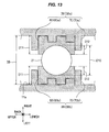
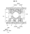
- Figs. 13 to 15 are views to explain an example of the method for fixing the wire protection tube 21 using the fixing portions 38b.
- the leg portions 62 of the left and right blocks 60a and 60b are engaged into the recesses 74 of their corresponding engaging portions 70a and 70b. Therefore, where the distance between the engaging portions 70a and 70b (the distance between the bottom surfaces 71a) is expressed as DD, the height of the blocks 60a and 60b when viewed from the bottom surface 71a (the size in the right and left direction) is expressed as D11 and the depth of the grooves 64 formed in the blocks 60a and 60b (the size in the right and left direction) is expressed as D12, the diameter size D10 of the wire protection tube 21 to be fixed by the paired fixing portions 38a and 38b can be expressed as in the expression 1.
- the leg portions 62 of the left and right blocks 60a and 60b are made to face the projecting sections 72 of their corresponding engaging portions 70a and 70b. Therefore, when the blocks 60a and 60b are held as in Fig. 14 , the diameter size D20 of the wire protection tube 21 to be fixed by the paired fixing portions 38a and 38b can be expressed as in the expression 2.
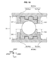
- the leg portions 62 of the blocks 60a are engaged into the recesses 74 of their corresponding engaging portions 70a, while the leg portions 62 of the blocks 60b are made to face the projecting sections of their corresponding engaging portions 70b. Therefore, when the height of the blocks 60a and 60b when viewed from the bottom surface 71a (the size in the right and left direction) is expressed as D31, the diameter size D30 of the wire protection tube 21 to be fixed by the paired fixing portions 38a and 38b can be expressed as in the expression 3.
- the pair of fixing portions 33, 38 or 53 in this embodiment can removably hold the blocks 60 using the corresponding engaging portions 70.
- protection tubes of various sizes can be fixed simply by selecting such blocks 60 as correspond to the size (the size in the width direction) of the wire protection tube 21. This can reduce the manufacturing cost of the feeding apparatus capable of coping with the wire protection tubes 21 of various sizes.
- the pair of fixing portions 33, 38 or 53 in this embodiment can select various distances between the grooves 40 by selecting the position relationships between the blocks 60 and engaging portions 70.
- one of D10, D20 and D30 can be selected. Therefore, without replacing the pair of blocks 60, they can be made to correspond to the multiple wire protection tubes 21 of various sizes (width direction sizes). This can further reduce the manufacturing cost of the feeding apparatus capable of coping with the wire protection tubes 21 of various sizes.
- the wire protection tube 21 is a substantially cylindrical elastic resin tube and the surface of the groove 64 formed in each block 60 is a substantially arc surface.
- the shapes of the wire protection tube 21 and groove 64 are not limited to this.
- the wire protection tube 21 there may also be used a prismatic-shaped elastic resin tube and, in the block 60, there may also be formed a groove 64 having a substantially prismatic shape.
- the heights of the two blocks 60a and 60b are the same.
- the heights of the two blocks 60a and 60b may also be different from each other.
- the pair of fixing portions 38a and 38b are able to fix the wire protection tubes 21 of a total of four kinds of diameter sizes.
Landscapes
- Engineering & Computer Science (AREA)
- Mechanical Engineering (AREA)
- Architecture (AREA)
- Civil Engineering (AREA)
- Structural Engineering (AREA)
- Electric Cable Arrangement Between Relatively Moving Parts (AREA)
- Details Of Indoor Wiring (AREA)
Abstract
Description
- The present invention relates to a feeding apparatus for feeding electric power to electric parts equipped in a slide door, and a fixing structure for use in such feeding apparatus.
- Conventionally, there is known a technology which uses an outer tube for protecting a wire harness for a slide door and fixes such outer tube with a clamp (for example, the patent document 1). And, there is also known conventionally a technology which uses a corrugated tube with multiple wires inserted inside therein and holds such corrugated tube on the main body of a fixing tool in such a manner that it can be rotated in the peripheral direction (for example, the patent document 2).
-
- Patent Document 1:
JP-A-2001-224118 - Patent Document 2:
JP-A-2002-199558 - Here, the diameter size of the outer tube or corrugated tube (which is also referred to as a tube simply) is selected according to the number of wires to be arranged within the tube. For example, as the number of electric parts to be equipped in the slide door increases, the number of wires to be arranged within a tube for feeding electricity to the slide door increases, resulting in the increased size of the tube to be selected. Thus, the proper diameter side of the tube is selected according to the number of wires to be arranged within the tube.
- However, the outer tube fixing method of the patent document 1 and the corrugated tube holding method of the patent document 2 are unable to cope with tubes of various different diameters. For example, the method of the patent document 1 needs staples respectively corresponding to such various tube diameters, and the method of the patent document 2 needs fixing tools respectively corresponding to such various tube diameters.
- Therefore, when there are used tubes of multiple diameter sizes, the feeding apparatus manufacturing cost disadvantageously increases.
- Thus, it is an object of the invention to provide a fixing structure capable of fixing a protection tube properly and a feeding apparatus using such fixing structure.
- In attaining the above object, according to a first embodiment of the invention, there is provided a feeding apparatus which includes an elastic protection tube, multiple wires to be arranged within the protection tube and, a fixing structure for fixing the protection tube. Specifically, the fixing structure includes a pair of blocks and a pair of holding portions. The paired holding portions respectively can hold their corresponding blocks removably, and the paired blocks respectively have such one side surface as extends along a first direction. To fix the protection tube by the fixing structure, the respective blocks may be held by their corresponding holding portions and the protection tube may be sandwiched between the respective grooves.
- Also, according to a second embodiment, in a feeding apparatus of the first embodiment, the pair of blocks each includes multiple leg portions respectively extending along a second direction, each of the pair of holding portions includes multiple projecting portions disposed correspondingly to the multiple leg portions and extending along the second direction. To hold the paired blocks by the paired holding portions, the leg portions may be engaged into recesses existing between the mutually adjoining projecting portions, or the respective leg portions and their corresponding projecting portions may be made to face each other.
- According to a third embodiment, in a feeding apparatus of the first or second embodiment, the surface of the groove formed in the one side surface is a substantially arc-shaped surface capable of fixing the protection tube having a substantially cylindrical shape.
- According to a fourth embodiment, in a feeding apparatus of the first or second embodiment, the shape of the groove formed in the one side surface is a substantially prismatic shape capable of fixing the protection tube having a substantially prismatic shape.
- Also, according to a fifth embodiment, there is provided a fixing structure for fixing an elastic protection tube, comprising: a pair of blocks; and, a pair of holding portions. The paired holding portions respectively can hold their corresponding blocks removably, and the paired blocks respectively include one side surface having a groove extending along a first direction. To fix the protection tube, the respective blocks may be held by their corresponding holding portions and the protection tube may be sandwiched between the respective grooves.
- According to a sixth embodiment, in a fixing structure of the fifth embodiment, each of the paired blocks includes multiple leg portions respectively extending along a second direction, and each of the paired holding portions includes multiple projecting portions disposed correspondingly to the multiple leg portions and extending along the second direction. And, to hold the paired blocks by the paired holding portions, the leg portions may be engaged into recesses existing between the mutually adjoining projecting portions, or the respective leg portions and their corresponding projecting portions may be made to face each other.
- According to a seventh embodiment, in a fixing structure of the fifth or sixth embodiment, the surface of the groove formed in the one side surface is a substantially arc-shaped surface capable of fixing the protection tube having a substantially cylindrical shape.
- According to an eighth embodiment, in a fixing structure of the fifth or sixth embodiment, the shape of the groove formed in the one side surface is a substantially prismatic shape capable of fixing the protection tube having a substantially prismatic shape.
- According to a feeding apparatus of the first embodiment and a fixing structure of the second embodiment, the paired blocks can be removably held by their corresponding holding portions. Therefore, without changing the structure of the paired holding portions, simply by selecting a block corresponding to the size (width direction size) of the protection tube, protection tubes of various sizes can be fixed. This can reduce the cost necessary to manufacture the feeding apparatus and fixing structure capable of coping with protection tubes of various sizes.
- According to a feeding apparatus of the second embodiment and a fixing structure of the sixth embodiment, by selecting the position relationship between the holding portions and blocks, various distances can be selected between the grooves. Therefore, without replacing the pair of blocks, the fixing structure is allowed to cope with multiple protection tubes of different sizes (width direction sizes). This can further reduce the cost necessary to manufacture the fixing structure and feeding apparatus capable of coping with protection tubes of various sizes.
- According to a feeding apparatus of the third embodiment and a fixing structure of the seventh embodiment, a protection tube having a substantially cylindrical shape can be fixed properly.
- According to a feeding apparatus of the fourth embodiment and a fixing structure of the eighth embodiment, a protection tube having a substantially prismatic shape can be fixed properly.
-
-
Fig. 1 is a side view of an example of the whole structure of a car to which a feeding apparatus according to an embodiment of the invention is applied. -
Fig. 2 is a side view of an example of a wiring structure for a slide door. -
Fig. 3 is a side view of an example of a wiring structure for a slide door. -
Fig. 4 is an exploded perspective view of an example of the structure of a slide door side feeding apparatus. -
Fig. 5 is a plan view of an example of a main body side feeding apparatus. -
Fig. 6 is a back view of an example of a main body side feeder apparatus. -
Fig. 7 is a side view of an example of a main body side feeder apparatus. -
Fig. 8 is a plan view of an example of the structure of a fixing portion. -
Fig. 9 is a side view of an example of the structure of a block for fixing a wire protection tube. -
Fig. 10 is a bottom view of an example of the structure of a block for fixing a wire protection tube. -
Fig. 11 is a back view of an example of the structure of a block for fixing a wire protection tube. -
Fig. 12 is a sectional bottom view when viewed from the V-V line shown inFig. 9 . -
Fig. 13 is an explanatory view of a method for fixing a wire protection tube using a fixing portion. -
Fig. 14 is an explanatory view of a method for fixing a wire protection tube using a fixing portion. -
Fig. 15 is an explanatory view of a method for fixing a wire protection tube using a fixing portion. -
Fig. 16 is an explanatory view of another method for fixing a wire protection tube using a fixing portion. - Now, description will be given below specifically of an embodiment of the invention with reference to the accompanying drawings.
-
Fig. 1 is a side view of an example of the whole structure of a car 1 to which a feeding apparatus according to an embodiment of the invention is applied. The car 1, as shown inFig. 1 , includes a substantially box-shaped car body 11, afront door 12 and aslide door 14, while such car is used as a passenger car or a truck. - The
front door 12 is an openable/closable door of a hinge type and thecar body 11 includes twofront doors 12 respectively provided on its right and left side surfaces. Theslide door 14 is an openable/closable door which can be moved forward and backward along thecar body 11. As shown inFig. 1 , theslide door 14 includes a slide doormain body 15. - Here, in
Fig. 1 , theslide door 14 is provided only on the left side surface of thecar body 11. However, the provision of theslide door 14 is not limited to this. For example, theslide door 14 may also be provided on one of the right and left side surfaces, or may be provided on both side surfaces. Also, as the openable/closable door of the car 1, instead of thefront door 12 of a hinge type, aslide door 14 of a forward and backward movable type may also be used. - The slide door
main body 15 mainly includes a metal-madeouter panel 15a and a resin-madeinner panel 15b. On the slide doormain body 15, there are mounted electric parts (not shown), for example, a motor for driving a power window or a switch for opening and closing the power window. Also, in a space surrounded by the outer andinner panels feeding wire structure 20. -
Figs. 2 and3 are respectively views of an example of afeeding wire structure 20 for theslide door 14. Thefeeding wire structure 20 prevents an unreasonable load from being applied to awire harness 22 without obstructing the forward/backward movements of the slide doormain body 15. As shown inFigs. 2 and3 , thefeeding wire structure 20 mainly includes a slide doorside feeding apparatus 30, atransition portion 40 and a main bodyside feeding apparatus 50. -
Fig. 4 is an exploded perspective view of an example of the structure of the slide doorside feeding apparatus 30. As shown inFig. 2 and3 , the slide doorside feeding apparatus 30 is fixed to the interior of the slide doormain body 15 and is used to feed electricity to electric parts (not shown) mounted on the slide doormain body 15. As shown inFig. 2 and3 , the slide doorside feeding apparatus 30 mainly includes awire protection tube 21, awire harness 22, abase portion 31 and anoscillation portion 35. - The
wire protection tube 21 is a substantially cylindrical-shaped elastic resin tube. As thewire protection tube 21, for example, there is used a corrugated tube. Thewire harness 22 is constituted of multiple wires respectively to be arranged within thewire protection tube 21 and is used to connect together thecar body 11 and slide doormain body 15 electrically. - To assemble the
base portion 31, left and right baseportion composing members Figs. 2 and3 , thebase portion 31 is fixed to a desired position in the slide doormain body 15. - Also, as shown in
Fig. 4 , the left and right baseportion composing members oscillation portion 35 between them from right and left sides. Therefore, theoscillation portion 35 can be oscillated about arotation axis 30a with respect to thebase portion 31. - A pair of fixing portions 33 (33a, 33b), as shown in
Fig. 4 , are respectively formed near the upper ends of the composingmembers wire protection tube 21 to thebase portion 31, it may be sandwiched between the left and right fixingportions 33a and 33b. That is, the paired fixingportions 33 are used as a fixing structure for fixing thewire protection tube 21 to be arranged within thebase portion 31. Here, the description of the specific structures of the fixingportions 33a and 33b will be given later. - To assemble the
oscillation portion 35, left and right oscillationportion composing members Fig. 4 , theoscillation portion 35 mainly includes atubular portion 36, an extended portion and a pair of fixingportions 38. - The
tubular portion 36, as shown inFig. 4 , is a hollow member extending from its oneend 36a existing on therotation axis 30a side toward itsother end 36b existing on the paired fixing portions 38 (38a and 38b) side. As shown inFigs. 2 and3 , the internal space of thetubular section 36 has substantially the same size as the outer size of thewire protection tube 21. - The paired fixing portions 38 (38a and 38b), as shown in
Fig. 4 , are respectively formed near theother end 36b of thetubular portion 36. When thewire protection tube 21 is sandwiched between the left and right fixingportions oscillation portion 35. That is, the paired fixingportions 38 are used as a fixing structure for fixing thewire protection tube 21 to be arranged within theoscillation portion 35. Here, the description of the specific structures of the fixingportions - With the forward and backward movements of the
slide door 14, theextended portion 37 guides the compressible or expandablewire protection tube 21 between the slide doorside feeding apparatus 30 and main bodyside feeding apparatus 50. As shown inFig. 4 , the width of the extendedportion 37 will spread out in the direction of an arrow R1 as it goes outwardly of theoscillation portion 35. This can also prevent an unreasonable load from being applied to thewire protection tube 21 andwire harness 22. - Here, in this embodiment, the
base portion 31 includes an energizing member (not shown) made of an elastic member such as a spring. As theoscillation portion 35 is oscillated in the arrow R1 direction when the slide doormain body 15 is moved from its closed position P1 (seeFig. 2 ) to its opened position P2 (seeFig. 3 ) and thewire protection tube 21 is thereby pulled, the energizing member energizes theoscillation portion 35 in the opposite direction to the arrow R1 direction. - Therefore, when the slide door
main body 15 moves from the opened portion P2 (seeFig. 3 ) toward the closed position P1 direction and thus thewire protection tube 21 is turned from its extended state to its compressed state, theoscillation portion 35 can be oscillated from a solid line position inFig. 3 to a one-dot chained line position inFig. 3 . - The
transition portion 40 is interposed between thecar body 11 and slidedoor 14 and is used to connect together the slide doorside feeding apparatus 30 and main bodyside feeding apparatus 50 electrically. In this embodiment, thetransition portion 40, as shown inFigs. 2 and3 , is defined by thewire protection tube 21 andwire harness 22. -
Figs. 5 to 7 are respectively plan view, back view and side view of an example of the structure of the main bodyside feeding apparatus 50. The main bodyside feeding apparatus 50 is fixed to thecar body 11 and is used to feed electricity from thecar body 11 side to the slide doormain body 15 side. As shown inFigs. 5 to 7 , the main bodyside feeding apparatus 50 mainly includes atubular portion 51, anextended portion 52 and a pair of fixingportions 53. - The
tubular portion 51 is a hollow portion which, as shown inFig. 6 , extends in the right and left direction substantially perpendicular to the forward/backward moving direction AR1 (the back and forth direction) of theslide door 14. As shown inFigs. 2 and3 , the internal space of thetubular portion 51, similarly to thetubular portion 36, has substantially the same size to the outer size of thewire protection tube 21. - The
extended portion 52, similarly to the extendedportion 37, guides the compressible or expandablewire protection tube 21 between the slide doorside feeding apparatus 30 and main bodyside feeding apparatus 50. The width of the extendedportion 52 increases as it goes in the left direction. This can prevent an unreasonable load from being applied to thewire protection tube 21 andwire harness 22. - The paired fixing portions 53 (53a and 53b), as shown in
Fig. 6 , are formed near the boundary between thetubular portion 51 andextended portion 52. When thewire protection tube 21 is sandwiched between the upper andlower fixing portions side feeding apparatus 50. Thus, the paired fixingportions 53 are used as a fixing structure for fixing thewire protection tube 21 to be arranged within the main bodyside feeding apparatus 50. Here, the specific structures of therespective fixing portions -
Fig. 8 shows an example of the structure of the fixingportion 38b. As shown inFigs. 4 and8 , the fixingportion 38a mainly includes a pair ofblocks 60 and a pair of engaging portions 70 (a pair of holding portions). Here, therespective fixing portions Fig. 4 ), 53a and 53b (seeFig. 6 ) are similar in structure. Therefore, the description thereof will be given below of the fixingportion 38b as a typical example. -
Figs. 9, 10 and11 are respectively the side view, bottom view and back view of an example of the structure of theblock 60 for fixing thewire protection tube 21. Also,Fig. 12 is a sectional bottom view taken along the V-V line shown inFig. 9 . As shown inFig. 10 , the pairedblocks 60 each mainly includes amain body portion 61 andleg portions 62. - The
multiple leg portions 62 each are projecting portions which, as shown inFigs. 10 to 12 , project in the left direction from the left side surface of themain body portion 61. Theleg portions 62 each, as shown inFig. 11 , extend along the vertical direction (second direction). Here, inFig. 8 and inFigs. 13 to 16 which will be described later, theleg portions 62 each will be described such that they extend along the back and forth direction for convenience of explanation of the method for fixing thewire protection tube 21. - The
main body portion 61, as shown inFig. 10 , is formed to have a substantially cuboid shape. Also, as shown inFig. 11 , themain body portion 61 includes a side surface having agroove 64 extending along the back and forth direction (first direction) . That is, thegroove 64 formed in this side surface is formed to have a substantially arc-like shape when viewed from behind. Further, as shown inFigs. 11 and 12 , themain body portion 61 includes multiple projectingportions 66 which respectively project from the surface (arc surface) 65 of thegroove 64 in the normal direction of thearc surface 65. - Referring back to
Fig. 8 , the engagingportion 70 is a holding portion for holding itscorresponding block 60 removably. As shown inFig. 8 , the engagingportion 70 mainly includes a surroundingsection 71 and a projectingsection 72. - The surrounding
section 71 is a frame member provided on thebottom surface 71a of the engagingportion 70. The inside size of the surroundingsection 71 is substantially the same as the outer size of theblock 60. Therefore, to hold theblock 60, it may be disposed in a space surrounded by the surroundingsection 71. - The multiple projecting
sections 72 respectively project in the right direction from thebottom surface 71a. The projectingsections 72 are disposed correspondingly to themultiple leg portions 62 and extend along the vertical direction (second direction). Therefore, between the mutually adjoining projectingsections 72, or between the surroundingsection 71 and projecting section, there is formed arecess 74 which extends in the vertical direction (second direction). - Here, in
Fig. 8 and inFigs. 13 to 16 which will be described later, each projectingsection 62 will be described such that, similarly to theleg portion 62, it extends along the back and forth direction for convenience of explanation of the method for fixing thewire protection tube 21. - Thus, to fix the
wire protection tube 21 using the paired fixingportions 38b, theblocks 60 may be respectively held by their correspondingengaging portions 70 and thewire protection tube 21 may be sandwiched between thegrooves 64 of the blocks 60 (especially, when a corrugated tube is used as thewire protection tube 21, ring-shaped projecting portions formed on the outer periphery of the corrugated tube may be engaged into their associated recesses respectively formed between the respective projections 66). -
Figs. 13 to 15 are views to explain an example of the method for fixing thewire protection tube 21 using the fixingportions 38b. - In
Fig. 13 , theleg portions 62 of the left andright blocks recesses 74 of their correspondingengaging portions portions bottom surfaces 71a) is expressed as DD, the height of theblocks bottom surface 71a (the size in the right and left direction) is expressed as D11 and the depth of thegrooves 64 formed in theblocks wire protection tube 21 to be fixed by the paired fixingportions -

- Also, in
Fig. 14 , theleg portions 62 of the left andright blocks sections 72 of their correspondingengaging portions blocks Fig. 14 , the diameter size D20 of thewire protection tube 21 to be fixed by the paired fixingportions -

- Further, in
Fig. 15 , theleg portions 62 of theblocks 60a are engaged into therecesses 74 of their correspondingengaging portions 70a, while theleg portions 62 of theblocks 60b are made to face the projecting sections of their correspondingengaging portions 70b. Therefore, when the height of theblocks bottom surface 71a (the size in the right and left direction) is expressed as D31, the diameter size D30 of thewire protection tube 21 to be fixed by the paired fixingportions -

- As described above, the pair of fixing
portions blocks 60 using the corresponding engagingportions 70. Without changing the structure of the engagingportions 70, protection tubes of various sizes can be fixed simply by selectingsuch blocks 60 as correspond to the size (the size in the width direction) of thewire protection tube 21. This can reduce the manufacturing cost of the feeding apparatus capable of coping with thewire protection tubes 21 of various sizes. - Also, the pair of fixing
portions grooves 40 by selecting the position relationships between theblocks 60 and engagingportions 70. For example, in this embodiment, it is possible to select any one of the following states: that is, (1) : a state where theleg portions 62 of the left andright blocks recesses 74 of their associatedengaging portions leg portions 62 of the left andright blocks sections 72 of their associatedengaging portions leg portions 62 of theblocks 60a are engaged into therecesses 74 of their correspondingengaging portions 70a, while theleg portions 62 of theblocks 60b are made to face the projecting sections of their correspondingengaging portions 70b. - That is, as the distance between the
grooves 64, one of D10, D20 and D30 can be selected. Therefore, without replacing the pair ofblocks 60, they can be made to correspond to the multiplewire protection tubes 21 of various sizes (width direction sizes). This can further reduce the manufacturing cost of the feeding apparatus capable of coping with thewire protection tubes 21 of various sizes. - Although description has been given heretofore of the embodiment of the invention, the invention is not limited to the above embodiment but other various modifications are also possible.
- (1) In the embodiment, description has been given such that the
wire protection tube 21 is a substantially cylindrical elastic resin tube and the surface of thegroove 64 formed in eachblock 60 is a substantially arc surface. However, the shapes of thewire protection tube 21 andgroove 64 are not limited to this. For example, as thewire protection tube 21, there may also be used a prismatic-shaped elastic resin tube and, in theblock 60, there may also be formed agroove 64 having a substantially prismatic shape. - (2) Also, in the embodiment, description has been given such that the heights of the two
blocks Fig. 16 , the heights of the twoblocks blocks 60 and engagingportions 70, the pair of fixingportions wire protection tubes 21 of a total of four kinds of diameter sizes. -
- 1: Car
- 14: Slide door
- 15: Slide door main body
- 20: Feeding wire structure
- 21: Wire protection tube
- 22: Wire harness
- 30: Slide door side feeding apparatus
- 33 (33a, 33b), 38 (38a, 38b), 53 (53a, 53b): Fixing portion
- 40: Transition portion
- 50: Main body side feeding apparatus
- 53: Fixing portion
- 60 (60a ~ 60c): Block
- 61: Main body portion
- 62: Leg portion
- 64: Groove
- 65: Groove surface
- 65: Arc shape
- 66: Projection
- 70 (70a ~ 70c): Engaging portion
- 71: Surrounding section
- 71a: Bottom surface
- 72: Projecting section
- 74: Groove
Claims (8)
- A feeding apparatus comprising:(a) an elastic protection tube;(b) multiple wires to be arranged within the protection tube; and(c) a fixing structure for fixing the protection tube, wherein:each of the pair of holding portions holds corresponding one of the blocks removably;the fixing structure includes:(c-1) a pair of blocks; and(c-2) a pair of holding portions;
each of the pair of blocks includes one side surface having a groove extending along a first direction; and
the protection tube is fixed by the fixing structure when the respective blocks are held by their corresponding holding portions and the protection tube is sandwiched between the respective grooves. - The feeding apparatus as set forth in Claim 1, wherein:each of the pair of blocks includes multiple leg portions respectively extending along a second direction;each of the pair of holding portions includes multiple projecting portions disposed correspondingly to the multiple leg portions and extending along the second direction; andthe pair of blocks is held by the pair of holding portions when (i) the leg portions are engaged into recesses existing between the mutually adjoining projecting portions, or when (ii) the respective leg portions are made to face their corresponding projecting portions.
- The feeding apparatus as set forth in Claim 1 or 2, wherein
the surface of the groove formed in the one side surface is a substantially arc-shaped surface capable of fixing the protection tube having a substantially cylindrical shape. - The feeding apparatus as set forth in Claim 1 or 2, wherein
the shape of the groove formed in the one side surface is a substantially prismatic shape capable of fixing the protection tube having a substantially prismatic shape. - A fixing structure for fixing an elastic protection tube comprising:(a) a pair of blocks; and(b) a pair of holding portions, wherein:each of the pair of holding portions holds corresponding one of the blocks removably; andeach of the pair of blocks includes one side surface having a groove extending along a first direction; andthe protection tube can be fixed when the respective blocks are held by their corresponding holding portions and the protection tube is sandwiched between the respective grooves.
- The fixing structure as set forth in Claim 5, wherein:each of the pair of blocks includes multiple leg portions respectively extending along a second direction;each of the pair of holding portions includes multiple projecting portions disposed correspondingly to the multiple leg portions and extending along the second direction; andthe pair of blocks is held by the pair of holding portions when (i) the respective leg portions are engaged into recesses existing between the mutually adjoining projecting portions, or when (ii) the respective leg portions are made to face their corresponding projecting portions.
- The fixing structure as set forth in Claim 5 or 6, wherein
the surface of the groove formed in the one side surface is a substantially arc-shaped surface capable of fixing the protection tube having a substantially cylindrical shape. - The fixing structure as set forth in Claim 5 or 6, wherein
the shape of the groove formed in the one side surface is a substantially prismatic shape capable of fixing the protection tube having a substantially prismatic shape.
Applications Claiming Priority (2)
| Application Number | Priority Date | Filing Date | Title |
|---|---|---|---|
| JP2009297816A JP5387397B2 (en) | 2009-12-28 | 2009-12-28 | Power supply device and fixed structure |
| PCT/JP2010/060270 WO2011080934A1 (en) | 2009-12-28 | 2010-06-17 | Power feeding apparatus and fixing structure |
Publications (2)
| Publication Number | Publication Date |
|---|---|
| EP2520467A1 true EP2520467A1 (en) | 2012-11-07 |
| EP2520467A4 EP2520467A4 (en) | 2015-11-04 |
Family
ID=44226357
Family Applications (1)
| Application Number | Title | Priority Date | Filing Date |
|---|---|---|---|
| EP10840793.3A Withdrawn EP2520467A4 (en) | 2009-12-28 | 2010-06-17 | Power feeding apparatus and fixing structure |
Country Status (3)
| Country | Link |
|---|---|
| EP (1) | EP2520467A4 (en) |
| JP (1) | JP5387397B2 (en) |
| WO (1) | WO2011080934A1 (en) |
Family Cites Families (4)
| Publication number | Priority date | Publication date | Assignee | Title |
|---|---|---|---|---|
| JPH10215514A (en) * | 1997-01-30 | 1998-08-11 | U C Sangyo Kk | Corrugated tube made of synthetic resin |
| JP2000299909A (en) * | 1999-04-13 | 2000-10-24 | Sumitomo Wiring Syst Ltd | Electric joint box |
| JP3741998B2 (en) * | 2001-11-14 | 2006-02-01 | 矢崎総業株式会社 | Corrugated tube rotation holder |
| JP2009213249A (en) * | 2008-03-04 | 2009-09-17 | Toyota Motor Corp | Wire harness wiring structure |
-
2009
- 2009-12-28 JP JP2009297816A patent/JP5387397B2/en not_active Expired - Fee Related
-
2010
- 2010-06-17 WO PCT/JP2010/060270 patent/WO2011080934A1/en not_active Ceased
- 2010-06-17 EP EP10840793.3A patent/EP2520467A4/en not_active Withdrawn
Also Published As
| Publication number | Publication date |
|---|---|
| JP2011136642A (en) | 2011-07-14 |
| JP5387397B2 (en) | 2014-01-15 |
| EP2520467A4 (en) | 2015-11-04 |
| WO2011080934A1 (en) | 2011-07-07 |
Similar Documents
| Publication | Publication Date | Title |
|---|---|---|
| DE102006058826B4 (en) | Harness cover and wiring harness structure with same | |
| EP3421410B1 (en) | Engagement chain and movable body movement device | |
| CN103717455A (en) | Wire harness routing structure | |
| DE102013105427A1 (en) | Protective and guide element for cables | |
| JP2008057759A (en) | Protection guiding device for cable or the like | |
| JP2008248999A (en) | Cable protective guide | |
| JP2014050152A (en) | Protector | |
| CN105453347A (en) | Connector and wire harness | |
| JP2005315382A (en) | Cables protection and guide device | |
| US7730669B2 (en) | Device for guiding a conductor path for slide door | |
| US20060219421A1 (en) | Cable or the like protection and guide device | |
| EP1473487A2 (en) | Cable or the like protection and guide device | |
| WO2017221676A1 (en) | Guide end of cable guide, cable guide, and wire harness | |
| US20160229360A1 (en) | Wire routing structure | |
| JP6987103B2 (en) | Clamps and wire harnesses | |
| EP2520467A1 (en) | Power feeding apparatus and fixing structure | |
| JP5929845B2 (en) | Wire harness wiring device for slide sheet | |
| JP2015101296A (en) | Exterior member, and wiring harness | |
| EP3032931A1 (en) | Holder and noise current absorber | |
| JP2013013183A (en) | Electric wire protection tool | |
| EP3043435B1 (en) | Power-supply structure for sliding structure | |
| JP5076840B2 (en) | Opening / closing body driving rack belt and opening / closing body driving apparatus using the opening / closing body driving rack belt | |
| JP5954244B2 (en) | Slider | |
| JP2011050182A (en) | Bending movement guiding member for conductive path and bending-movement guiding apparatus for conductive-path of sliding-door | |
| JP2007135299A (en) | Chain protector for wiring material and protective structure for wiring material |
Legal Events
| Date | Code | Title | Description |
|---|---|---|---|
| PUAI | Public reference made under article 153(3) epc to a published international application that has entered the european phase |
Free format text: ORIGINAL CODE: 0009012 |
|
| 17P | Request for examination filed |
Effective date: 20120705 |
|
| AK | Designated contracting states |
Kind code of ref document: A1 Designated state(s): AL AT BE BG CH CY CZ DE DK EE ES FI FR GB GR HR HU IE IS IT LI LT LU LV MC MK MT NL NO PL PT RO SE SI SK SM TR |
|
| DAX | Request for extension of the european patent (deleted) | ||
| RA4 | Supplementary search report drawn up and despatched (corrected) |
Effective date: 20151007 |
|
| RIC1 | Information provided on ipc code assigned before grant |
Ipc: H02G 11/00 20060101ALI20151001BHEP Ipc: H02G 3/30 20060101ALI20151001BHEP Ipc: B60R 16/02 20060101AFI20151001BHEP |
|
| GRAP | Despatch of communication of intention to grant a patent |
Free format text: ORIGINAL CODE: EPIDOSNIGR1 |
|
| INTG | Intention to grant announced |
Effective date: 20160421 |
|
| STAA | Information on the status of an ep patent application or granted ep patent |
Free format text: STATUS: THE APPLICATION IS DEEMED TO BE WITHDRAWN |
|
| 18D | Application deemed to be withdrawn |
Effective date: 20160902 |