EP2520154A1 - Combine header with crop compression rollers - Google Patents
Combine header with crop compression rollers Download PDFInfo
- Publication number
- EP2520154A1 EP2520154A1 EP12165323A EP12165323A EP2520154A1 EP 2520154 A1 EP2520154 A1 EP 2520154A1 EP 12165323 A EP12165323 A EP 12165323A EP 12165323 A EP12165323 A EP 12165323A EP 2520154 A1 EP2520154 A1 EP 2520154A1
- Authority
- EP
- European Patent Office
- Prior art keywords
- header
- crop
- belt conveyors
- crop compression
- compression rollers
- Prior art date
- Legal status (The legal status is an assumption and is not a legal conclusion. Google has not performed a legal analysis and makes no representation as to the accuracy of the status listed.)
- Granted
Links
Images



Classifications
-
- A—HUMAN NECESSITIES
- A01—AGRICULTURE; FORESTRY; ANIMAL HUSBANDRY; HUNTING; TRAPPING; FISHING
- A01D—HARVESTING; MOWING
- A01D61/00—Elevators or conveyors for binders or combines
- A01D61/002—Elevators or conveyors for binders or combines transversal conveying devices
Definitions
- This invention relates to headers for agricultural combines. More particularly, it relates to headers with belt conveyors for a lateral transport of the crop. Even more particularly, it relates to headers having crop compression rollers above the laterally feeding belt conveyors.
- Draper platforms are a type of header for an agricultural combine that use side to side belt conveyors rather than augers to carry crop material that is cut from the field by a cutter bar. These conveyors extend laterally from opposite lateral ends of the platform to a central region of the header. A central conveyor disposed between the two lateral conveyors receives crop from both the lateral conveyors and carries the crop rearward to the inlet of a feeder house which then carries the crop to the combine vehicle for threshing, separating and cleaning.
- the lateral transport of the crop is only performed by the lateral belt conveyors.
- a header for an agricultural combine is arranged to be moved in a forward direction over a field.
- the header comprises a laterally extending frame supporting a laterally extending cutter bar.
- Laterally extending and generally vertical back sheets are disposed along the back of the header on left and right sides of the header.
- the back sheets have a central aperture therebetween.
- Left and right lateral belt conveyors are supported on the frame. Each of said belt conveyors has a feeding direction from an outer side end towards a center of the header.
- a central conveyor is disposed between the inner ends of the left and right lateral belt conveyors to receive cut crop material therefrom and convey it rearward through the aperture.
- Rotationally drivable left and right crop compression rollers are supported on the frame forward of the back sheets and above the left and right lateral belt conveyors.
- the crop compression rollers extend substantially over the length of the left and right lateral belt conveyors and have a laterally extending rotational axis and a smooth cylindrical surface with a circular cross section.
- a self-propelled agricultural combine 10 comprising a supporting structure 12 supported on front wheels 14 and rear wheels 16, a feeder house 18 coupled to, extending forward from, and supported on the supporting structure, and a header 20 coupled to and supported on the front of the feeder house 18.
- the combine 10 drives in a forward direction over a field and receives cut crop material from the header 20 via the feeder house 18 and conveys it to an internal threshing and separating assembly 22.
- the threshed grain is cleaned in a cleaning section 24.
- the combine 10 deposits the grain in a grain tank 26.
- all direction references like laterally, left and right, are given with respect to the forward direction, extending in Figure 1 from the right to the left.
- Feeder house 18 is pivotally coupled (around a horizontal and laterally extending axis) to the front of the combine 10. It has a conveyor 27 extending across the bottom of the feeder house 18 that conveys cut crop material rearward and into the threshing and separating assembly 22 of the combine 10.
- Header 20 is coupled to and supported on the front of the feeder house 18. It has a frame 28 that extends generally horizontally across the width of the header 20, back sheets 30 (cf. Figure 2 ) that extend generally vertically across the width of the header 20, and a conveying system comprising left and right lateral belt conveyors 32, 34 respectively, central conveyor 36, and feed drum 38.
- the left and right lateral belt conveyors 32, 34 extend laterally across the width of the header 20 on the left and right sides of the header 20, respectively. Each of them comprises an endless belt 40 that is supported at its inner and outer ends on rollers, respectively (not shown, but reference is made to the disclosure of US 2008/0098705 A , the contents of which incorporated herein by reference).
- the inner rollers are mounted adjacent to a longitudinal center line of the header 20 providing a gap in between in which the central conveyor 36 is disposed.
- the endless belts 40 are coupled to motors (not shown) that drive the top surface of the belts 40 inwardly from the outer ends of the header 20 to a central region where the central conveyor 36 is located. It should be mentioned that two or more left and right lateral belt conveyors 32, 34 can be provided on both sides of the header 20, in particular for larger working widths.
- the outer lateral belt conveyor would then feed its crop to an inner lateral belt conveyor.
- the central conveyor 36 comprises an endless belt 42 that is supported on a laterally extending front roller 44 and laterally extending rear roller 46.
- the front and rear rollers 44, 46 are disposed forward of the generally vertical back sheets 30 and slightly below the rollers of the left and right side belt conveyors 32, 34, such that cut crop material arriving at the central conveyor 36 must fall downward from the left and right lateral belt conveyors 32, 34 in order to rest on and engage the central conveyor 36.
- Feed drum 38 extends laterally across the width of a central aperture 48 in the back sheets 30 of the header 20. It is partly disposed in the aperture 48 above the central conveyor 36 and just behind the rear roller 46. It has a plurality of fingers 50 extending therefrom that rotate together with the feed drum 38 to convey cut crop material from the central conveyor 36 rearward, underneath the feed drum 38 on a floor 52, and toward the feeder house 18.
- a cutter bar 54 is provided for cutting the crop standing on a field.
- a reel 56 is supported on the frame 28 by means of arms 58 that can be moved up and down by hydraulic cylinders 60. The fore-and-aft position of the reel 58 can be altered by additional cylinders (not shown).
- the frame 28 comprises a laterally extending beam 62 on which the left and right lateral belt conveyors 32, 34, the central conveyor 36 and the cutter bar 54 are rigidly or floatingly supported.
- Vertical bearers 64 mount an upper cross beam 66 to beam 62.
- Upper cross beam 66 is hooked to the upper front end of the feeder house 18.
- the back sheets 30 are also mounted to the frame 28 and have a lower portion 68 extending vertically from the rear edges or the left and right lateral belt conveyors 32, 34, a center portion 70 above the lower portion 68 extending upwards and rearwards from the upper edge of the lower portion 68, and an upper portion 72 extending vertically from the upper edge of the center portion 70.
- Crop compression rollers 74 are mounted above the rear portion of the left and right lateral belt conveyors 32, 34.
- the crop compression rollers 74 extend horizontally in a lateral direction substantially over the lateral extension of the left and right lateral belt conveyors 32, 34.
- the inner end of the crop compression rollers 74 is in close vicinity of the inner end of the respective left and right lateral belt conveyor 32, 34.
- the outer end of the crop compression rollers 74 is in close vicinity of the outer end of the respective left and right lateral belt conveyor 32, 34 and of side walls 132 of the header 20.
- the crop compression rollers 74 have a circle shaped cross section and are cylindrical without any ridges or edges. Thus, their surface is entirely smooth. They rotate during operation around their central axis that extends horizontally and laterally.
- the crop compression rollers 74 are supported on their both ends on the frame 28 by arms 76.
- the arms 76 pivot at their rear end on horizontal, laterally extending axes 78.
- the arms 76 each comprise a first part 80 in the form of a hollow tube with rectangular cross section supporting the crop compression rollers 74 and a second part 82 in the form of a hollow tube with rectangular cross section supported on the frame 28.
- the second part 82 is pivotably supported between two brackets 100 which are preferably welded to the upper cross beam 66.
- the first part 80 is connected to the second part 82 by removable bolts 84.
- the first part 80 can be telescoped with respect to the second part 82 and fixed in a different position in order to alter the fore-aft-position of the crop compression rollers 74, as indicated in Figures 6 and 7 .
- a stop mechanism comprising a bar 86 that is on its rear end fixed to a first laterally extending member 88 that can pivot with respect to frame 28 around a laterally extending axis 90.
- Bar 86 also extends through a second laterally extending member 92 that can pivot with respect to the second part 82 of the arm 76 around a laterally extending axis 94.
- Inner and outer stop elements 96, 98 on both sides of the second member 92 limit the possible movement of the arm 76 around the axis 78, as indicated in Figures 6 and 7 .
- the crop compression rollers 74 each comprise a shell 102 that receives two support disks 104 in the vicinity of both ends, respectively.
- the two disks 104 adjacent the inner end of the crop compression rollers 74 are connected to a central axle 106 that is rotatably supported in a bearing 108 outside the crop compression roller 74.
- the bearing 108 is mounted in a bracket 110 connected to the first part 80 of the arm 76 by means of bolts 112.
- a short tube 114 mounted to the bracket 110 extends through a central opening in an end ring 116 of the crop compression roller 74.
- the two disks 104 adjacent the outer end of the crop compression rollers 74 are connected to a central shaft 118 that is rotatably supported in a bearing 120.
- the bearing 120 is mounted in a bracket 122 connected to the first part 80 of the arm 76 by means of bolts 124.
- a short tube 126 mounted to the bracket 122 surrounds the outer end portion of the crop compression roller 74.
- the shaft 118 is connected to an output shaft 126 of a hydraulic motor 128.
- the hydraulic motor 128 drives the respective crop compression roller 74 such that its front face moves downwards, as indicated by arrow 130.
- the hydraulic motor 128 is powered from the hydraulic system of the header 20 or of the combine 10 and its speed can be fixed or variable, in particular to be controlled from the operator station of the combine 10.
- the cutter bar 54 cuts the crop that stands or lies on the field in front of the header 20.
- the cut crop is then fed by the respective left and right lateral belt conveyor 32, 34 and then by the central conveyor 36 and the feed roller 38 through the outlet 48.
- Some types of crop, like rape, tend to build bridges between the cutter bar 54 and the rear walls 30.
- the crop compression rollers 74 compress the crop mat above the respective left and right lateral belt conveyors 32, 34 such that their cleats can remove the crop.
- the crop compression rollers 74 thus help to avoid crop accumulations above the left and right lateral belt conveyors 32, 34.
- the rotation speed of the crop compression rollers 74 does not need to be adjusted to the speed of the left and right lateral belt conveyors 32, 34.
- the tubes 114, 126 help avoiding that crop enters into the crop compression rollers 74 and crop accumulations in this area.
- positioning of the left and right crop compression rollers 74 is shown as performed manually by removing the bolts 84 and telescoping the first part 80 with respect to the second part 82.
- the fore-aft-position of the compression rollers 74 could be adjusted by hydraulic cylinders or electric actuators (not shown) that can preferably be remotely controlled by an operator from the cab of the combine 10.
- Such cylinders or actuators can be mounted inside or outside the first part 80 and second part 82 in order to provide the telescoping motion.
- compression rollers 74 are shown as arranged exactly transversely to the forward direction of the header 20 and horizontally.
- their outer ends could be in a fixed or manually or remotely controlled adjustable manner located further to the front or to the rear than their inner ends which are located close to the central conveyor 36 in order to provide a converging or diverging effect.
- the outer ends of compression rollers 74 could be in a fixed or manually or remotely controlled adjustable manner located higher or lower in a vertical direction than their inner ends.
- the vertical and/or fore-aft-position of one or both ends of each crop compression roller 74 is separately adjusted manually or by a respective hydraulic cylinder or electric actuator that can be remotely controlled by an operator from the cab of the combine 10.
Landscapes
- Life Sciences & Earth Sciences (AREA)
- Environmental Sciences (AREA)
- Harvester Elements (AREA)
- Harvesting Machines For Specific Crops (AREA)
Abstract
Description
- This invention relates to headers for agricultural combines. More particularly, it relates to headers with belt conveyors for a lateral transport of the crop. Even more particularly, it relates to headers having crop compression rollers above the laterally feeding belt conveyors.
- Draper platforms are a type of header for an agricultural combine that use side to side belt conveyors rather than augers to carry crop material that is cut from the field by a cutter bar. These conveyors extend laterally from opposite lateral ends of the platform to a central region of the header. A central conveyor disposed between the two lateral conveyors receives crop from both the lateral conveyors and carries the crop rearward to the inlet of a feeder house which then carries the crop to the combine vehicle for threshing, separating and cleaning.
- Normally, the lateral transport of the crop is only performed by the lateral belt conveyors. Some types of crop, like rape, tend to collect between the cutter bar and the back sheets of the header and build accumulations that the belt cannot remove. It was tried to remove such accumulations by laterally extending top augers mounted above the lateral belt conveyors. The top augers engage the crop material near the back sheets and keep the flow of material moving towards the central conveyor of the platform. However, if the auger speed is not closely matched to the speed of the lateral belt conveyors, the auger flights can disrupt the flow of crop material.
- What is needed therefore is an improved top conveyor arrangement for mounting above the lateral belt conveyors of a draper platform that improves the lateral crop feeding process but is less dependent on the feeding speed of the lateral belt conveyors. It is an object of this invention to provide such a conveyor arrangement.
- This object is achieved with the subject matter of
claim 1. The dependent claims recite advantageous features of embodiments of the invention. - A header for an agricultural combine is arranged to be moved in a forward direction over a field. The header comprises a laterally extending frame supporting a laterally extending cutter bar. Laterally extending and generally vertical back sheets are disposed along the back of the header on left and right sides of the header. The back sheets have a central aperture therebetween. Left and right lateral belt conveyors are supported on the frame. Each of said belt conveyors has a feeding direction from an outer side end towards a center of the header. A central conveyor is disposed between the inner ends of the left and right lateral belt conveyors to receive cut crop material therefrom and convey it rearward through the aperture. Rotationally drivable left and right crop compression rollers are supported on the frame forward of the back sheets and above the left and right lateral belt conveyors. The crop compression rollers extend substantially over the length of the left and right lateral belt conveyors and have a laterally extending rotational axis and a smooth cylindrical surface with a circular cross section.
- An embodiment of the invention is shown in the drawings, in which:
-
Figure 1 is a side view of an agricultural combine supporting a header in accordance with the present invention. -
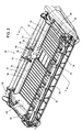
Figure 2 is a perspective view of the header from the front left side. -
Figure 3 is section through the header along the lines 3-3- ofFigure 2 . -
Figure 4 is an enlarged perspective view of the left half of the header. -
Figure 5 is an enlarged perspective view of the left end of the crop compression roller ofFigure 4 . -
Figures 6 and 7 are end views of the crop compression roller in its lowest and highest positions, respectively. -
Figure 8 is a perspective, partially cut view of the right end of the crop compression roller ofFigure 4 . -
Figure 9 is a perspective, partially cut view of the left end of the crop compression roller ofFigure 4 . - Referring now to
Figure 1 , a self-propelledagricultural combine 10 is shown comprising a supportingstructure 12 supported onfront wheels 14 andrear wheels 16, afeeder house 18 coupled to, extending forward from, and supported on the supporting structure, and aheader 20 coupled to and supported on the front of thefeeder house 18. During operation, thecombine 10 drives in a forward direction over a field and receives cut crop material from theheader 20 via thefeeder house 18 and conveys it to an internal threshing and separatingassembly 22. The threshed grain is cleaned in acleaning section 24. Once cleaned, the combine 10 deposits the grain in agrain tank 26. In the following, all direction references like laterally, left and right, are given with respect to the forward direction, extending inFigure 1 from the right to the left. -
Feeder house 18 is pivotally coupled (around a horizontal and laterally extending axis) to the front of thecombine 10. It has aconveyor 27 extending across the bottom of thefeeder house 18 that conveys cut crop material rearward and into the threshing and separatingassembly 22 of thecombine 10. -
Header 20 is coupled to and supported on the front of thefeeder house 18. It has aframe 28 that extends generally horizontally across the width of theheader 20, back sheets 30 (cf.Figure 2 ) that extend generally vertically across the width of theheader 20, and a conveying system comprising left and rightlateral belt conveyors central conveyor 36, andfeed drum 38. - The left and right
lateral belt conveyors header 20 on the left and right sides of theheader 20, respectively. Each of them comprises anendless belt 40 that is supported at its inner and outer ends on rollers, respectively (not shown, but reference is made to the disclosure ofUS 2008/0098705 A , the contents of which incorporated herein by reference). The inner rollers are mounted adjacent to a longitudinal center line of theheader 20 providing a gap in between in which thecentral conveyor 36 is disposed. Theendless belts 40 are coupled to motors (not shown) that drive the top surface of thebelts 40 inwardly from the outer ends of theheader 20 to a central region where thecentral conveyor 36 is located. It should be mentioned that two or more left and rightlateral belt conveyors header 20, in particular for larger working widths. The outer lateral belt conveyor would then feed its crop to an inner lateral belt conveyor. - Referring now to
Figure 3 , thecentral conveyor 36 comprises anendless belt 42 that is supported on a laterally extendingfront roller 44 and laterally extendingrear roller 46. The front andrear rollers vertical back sheets 30 and slightly below the rollers of the left and rightside belt conveyors central conveyor 36 must fall downward from the left and rightlateral belt conveyors central conveyor 36. - Feed
drum 38 extends laterally across the width of acentral aperture 48 in theback sheets 30 of theheader 20. It is partly disposed in theaperture 48 above thecentral conveyor 36 and just behind therear roller 46. It has a plurality offingers 50 extending therefrom that rotate together with thefeed drum 38 to convey cut crop material from thecentral conveyor 36 rearward, underneath thefeed drum 38 on afloor 52, and toward thefeeder house 18. - At the front end of the
header 20, acutter bar 54 is provided for cutting the crop standing on a field. Areel 56 is supported on theframe 28 by means ofarms 58 that can be moved up and down byhydraulic cylinders 60. The fore-and-aft position of thereel 58 can be altered by additional cylinders (not shown). Theframe 28 comprises a laterally extendingbeam 62 on which the left and rightlateral belt conveyors central conveyor 36 and thecutter bar 54 are rigidly or floatingly supported.Vertical bearers 64 mount anupper cross beam 66 tobeam 62.Upper cross beam 66 is hooked to the upper front end of thefeeder house 18. Theback sheets 30 are also mounted to theframe 28 and have alower portion 68 extending vertically from the rear edges or the left and rightlateral belt conveyors center portion 70 above thelower portion 68 extending upwards and rearwards from the upper edge of thelower portion 68, and anupper portion 72 extending vertically from the upper edge of thecenter portion 70. -
Crop compression rollers 74 are mounted above the rear portion of the left and rightlateral belt conveyors crop compression rollers 74 extend horizontally in a lateral direction substantially over the lateral extension of the left and rightlateral belt conveyors crop compression rollers 74 is in close vicinity of the inner end of the respective left and rightlateral belt conveyor crop compression rollers 74 is in close vicinity of the outer end of the respective left and rightlateral belt conveyor side walls 132 of theheader 20. Thecrop compression rollers 74 have a circle shaped cross section and are cylindrical without any ridges or edges. Thus, their surface is entirely smooth. They rotate during operation around their central axis that extends horizontally and laterally. - The
crop compression rollers 74 are supported on their both ends on theframe 28 byarms 76. Thearms 76 pivot at their rear end on horizontal, laterally extendingaxes 78. Thearms 76 each comprise afirst part 80 in the form of a hollow tube with rectangular cross section supporting thecrop compression rollers 74 and asecond part 82 in the form of a hollow tube with rectangular cross section supported on theframe 28. Thesecond part 82 is pivotably supported between twobrackets 100 which are preferably welded to theupper cross beam 66. Thefirst part 80 is connected to thesecond part 82 byremovable bolts 84. Once thebolts 84 are removed, thefirst part 80 can be telescoped with respect to thesecond part 82 and fixed in a different position in order to alter the fore-aft-position of thecrop compression rollers 74, as indicated inFigures 6 and 7 . - The highest and lowest possible positions of the
arms 76 and thus thecrop compression rollers 74 are defined by a stop mechanism comprising abar 86 that is on its rear end fixed to a first laterally extendingmember 88 that can pivot with respect to frame 28 around a laterally extendingaxis 90.Bar 86 also extends through a second laterally extendingmember 92 that can pivot with respect to thesecond part 82 of thearm 76 around a laterally extendingaxis 94. Inner andouter stop elements second member 92 limit the possible movement of thearm 76 around theaxis 78, as indicated inFigures 6 and 7 . - As shown in
Figures 8 and9 , thecrop compression rollers 74 each comprise ashell 102 that receives twosupport disks 104 in the vicinity of both ends, respectively. The twodisks 104 adjacent the inner end of thecrop compression rollers 74 are connected to acentral axle 106 that is rotatably supported in abearing 108 outside thecrop compression roller 74. Thebearing 108 is mounted in abracket 110 connected to thefirst part 80 of thearm 76 by means ofbolts 112. Ashort tube 114 mounted to thebracket 110 extends through a central opening in anend ring 116 of thecrop compression roller 74. - The two
disks 104 adjacent the outer end of thecrop compression rollers 74 are connected to acentral shaft 118 that is rotatably supported in abearing 120. Thebearing 120 is mounted in abracket 122 connected to thefirst part 80 of thearm 76 by means ofbolts 124. Ashort tube 126 mounted to thebracket 122 surrounds the outer end portion of thecrop compression roller 74. Theshaft 118 is connected to anoutput shaft 126 of ahydraulic motor 128. During operation, thehydraulic motor 128 drives the respectivecrop compression roller 74 such that its front face moves downwards, as indicated byarrow 130. Thehydraulic motor 128 is powered from the hydraulic system of theheader 20 or of thecombine 10 and its speed can be fixed or variable, in particular to be controlled from the operator station of thecombine 10. - During the harvesting operation, the
cutter bar 54 cuts the crop that stands or lies on the field in front of theheader 20. The cut crop is then fed by the respective left and rightlateral belt conveyor central conveyor 36 and thefeed roller 38 through theoutlet 48. Some types of crop, like rape, tend to build bridges between thecutter bar 54 and therear walls 30. Thecrop compression rollers 74 compress the crop mat above the respective left and rightlateral belt conveyors crop compression rollers 74 thus help to avoid crop accumulations above the left and rightlateral belt conveyors crop compression rollers 74 does not need to be adjusted to the speed of the left and rightlateral belt conveyors tubes crop compression rollers 74 and crop accumulations in this area. - Having described the preferred embodiment, it will become apparent that various modifications can be made without departing from the scope of the invention as defined in the accompanying claims. For example, positioning of the left and right
crop compression rollers 74 is shown as performed manually by removing thebolts 84 and telescoping thefirst part 80 with respect to thesecond part 82. Instead, the fore-aft-position of thecompression rollers 74 could be adjusted by hydraulic cylinders or electric actuators (not shown) that can preferably be remotely controlled by an operator from the cab of thecombine 10. Such cylinders or actuators can be mounted inside or outside thefirst part 80 andsecond part 82 in order to provide the telescoping motion. - Further, the
compression rollers 74 are shown as arranged exactly transversely to the forward direction of theheader 20 and horizontally. In another embodiment, their outer ends could be in a fixed or manually or remotely controlled adjustable manner located further to the front or to the rear than their inner ends which are located close to thecentral conveyor 36 in order to provide a converging or diverging effect. Analogously, the outer ends ofcompression rollers 74 could be in a fixed or manually or remotely controlled adjustable manner located higher or lower in a vertical direction than their inner ends. Thus, in a possible embodiment, the vertical and/or fore-aft-position of one or both ends of eachcrop compression roller 74 is separately adjusted manually or by a respective hydraulic cylinder or electric actuator that can be remotely controlled by an operator from the cab of thecombine 10.
Claims (9)
Applications Claiming Priority (1)
| Application Number | Priority Date | Filing Date | Title |
|---|---|---|---|
| US13/100,746 US8166738B1 (en) | 2011-05-04 | 2011-05-04 | Combine header with crop compression rollers |
Publications (2)
| Publication Number | Publication Date |
|---|---|
| EP2520154A1 true EP2520154A1 (en) | 2012-11-07 |
| EP2520154B1 EP2520154B1 (en) | 2014-07-09 |
Family
ID=45990721
Family Applications (1)
| Application Number | Title | Priority Date | Filing Date |
|---|---|---|---|
| EP12165323.2A Active EP2520154B1 (en) | 2011-05-04 | 2012-04-24 | Combine header with crop compression rollers |
Country Status (5)
| Country | Link |
|---|---|
| US (1) | US8166738B1 (en) |
| EP (1) | EP2520154B1 (en) |
| AU (1) | AU2012202549B2 (en) |
| BR (1) | BR102012010700B1 (en) |
| CA (1) | CA2774547C (en) |
Cited By (3)
| Publication number | Priority date | Publication date | Assignee | Title |
|---|---|---|---|---|
| CN104798530A (en) * | 2014-01-24 | 2015-07-29 | 甘肃农业大学 | Machining method of herringbone-tooth rubber compression roller |
| EP3417694A1 (en) * | 2017-06-21 | 2018-12-26 | Carl Geringhoff GmbH & Co. KG | Draper header with multi-part conveying screw |
| EP4470358A1 (en) * | 2023-05-31 | 2024-12-04 | CLAAS Selbstfahrende Erntemaschinen GmbH | Self-propelled combine harvester with a header |
Families Citing this family (13)
| Publication number | Priority date | Publication date | Assignee | Title |
|---|---|---|---|---|
| US9750190B2 (en) * | 2013-12-11 | 2017-09-05 | Deere & Company | Harvesting head upper belt conveyor compressing crop against a center belt conveyor |
| US20150156969A1 (en) * | 2013-12-11 | 2015-06-11 | Deere & Company | Harvesting head |
| CN103828540B (en) * | 2014-03-07 | 2015-09-23 | 星光农机股份有限公司 | The ceding of Taiwan of combine |
| WO2017143418A1 (en) * | 2016-02-23 | 2017-08-31 | Vanderlei Kamphorst | System for conveying cut material for use in cutting platform for grain harvester |
| US10219435B2 (en) | 2016-11-21 | 2019-03-05 | Cnh Industrial America Llc | Corn header for an agricultural harvester having an active hood |
| US10299435B2 (en) * | 2017-03-22 | 2019-05-28 | Cnh Industrial America Llc | Self-storing header auger |
| US10477770B2 (en) * | 2017-07-28 | 2019-11-19 | Deere & Company | Draper platform with reconfigurable central roller baffle |
| US10477767B2 (en) * | 2017-07-28 | 2019-11-19 | Deere & Company | Draper platform with removable central roller baffle |
| US10806081B2 (en) * | 2017-09-14 | 2020-10-20 | Deere & Company | Crop deflector for a harvesting head |
| CN107803017A (en) * | 2017-11-10 | 2018-03-16 | 浙江宣和电器有限公司 | Card machine and its device and method for arranging mahjong |
| US10820515B2 (en) | 2018-06-28 | 2020-11-03 | Deere & Company | Combine header with feed assist bulky crop auger on a draper platform |
| US11758850B2 (en) * | 2019-09-30 | 2023-09-19 | Deere & Company | Combine header with split augers and method of using the same |
| US11419268B2 (en) * | 2019-10-18 | 2022-08-23 | Cnh Industrial America Llc | Multi-segment header for an agricultural harvester |
Citations (3)
| Publication number | Priority date | Publication date | Assignee | Title |
|---|---|---|---|---|
| US4956966A (en) * | 1988-06-22 | 1990-09-18 | Macdon Industries Ltd. | Header for a combine harvesting machine |
| US20080098705A1 (en) | 2006-10-26 | 2008-05-01 | Deere & Company | Combine header with feed drum |
| WO2009136275A1 (en) * | 2008-05-09 | 2009-11-12 | Agco Corporation | Spring flotation for center deck of draper header |
Family Cites Families (22)
| Publication number | Priority date | Publication date | Assignee | Title |
|---|---|---|---|---|
| US885157A (en) * | 1907-02-25 | 1908-04-21 | August Hovland | Central-delivery reaper. |
| US2515808A (en) * | 1946-10-31 | 1950-07-18 | Glen W Stoddard | Corn picking machine |
| US2608041A (en) * | 1947-01-24 | 1952-08-26 | Case Co J I | Conveying means for harvester headers |
| BE672436A (en) * | 1964-11-27 | 1966-03-16 | ||
| US3584443A (en) * | 1969-03-19 | 1971-06-15 | Case Co J I | Corn header for combines |
| US3681901A (en) * | 1971-03-08 | 1972-08-08 | Univ Iowa State Res Found | Cutting knife assembly for a combine |
| DD122191A2 (en) | 1975-10-29 | 1976-09-20 | ||
| US4070810A (en) * | 1976-08-13 | 1978-01-31 | Henry Donald Brakke | Cutting apparatus |
| DE3227975A1 (en) * | 1982-07-27 | 1984-02-09 | Claas Ohg, 4834 Harsewinkel | SELF-DRIVING COMBINATION |
| US4487004A (en) * | 1983-06-03 | 1984-12-11 | Kejr Melvin P | Combine harvester apparatus |
| US4512140A (en) * | 1983-09-16 | 1985-04-23 | Sperry Corporation | Stub draper drive for draper header |
| US4589250A (en) * | 1984-12-04 | 1986-05-20 | Faul Manufacturing, Inc. | Sunflower header attachment for combine |
| FR2602392B1 (en) * | 1986-08-06 | 1988-11-18 | Sionneau Patrick | HARVESTER SUPPLY CUTTING GEAR |
| US5005343A (en) | 1988-06-22 | 1991-04-09 | Macdon Industries Ltd. | Header for a combine harvesting machine |
| DE4108494A1 (en) | 1991-03-15 | 1992-09-17 | Kloeckner Humboldt Deutz Ag | CUTTERS FOR COMBINATION |
| CA2110775C (en) * | 1993-12-06 | 1999-03-02 | Gregory J. Honey | A feeder adapter for mounting a combine header to a feeder housing of a combine |
| US5440865A (en) * | 1994-02-22 | 1995-08-15 | Hale; Elcie C. | Crop cutting assembly |
| DE19939723A1 (en) * | 1999-08-21 | 2001-02-22 | Kemper Gmbh Maschf | Harvester for harvesting corn cobs or the like cereals |
| US6865871B2 (en) * | 2003-07-14 | 2005-03-15 | Macdon Industries Ltd. | Crop feed arrangement for the header of a combine harvester |
| US7726111B2 (en) * | 2005-06-30 | 2010-06-01 | Deere & Company | Suspension system for a belt pickup header in an agricultural harvester |
| US7958711B1 (en) * | 2010-06-16 | 2011-06-14 | Agco Corporation | Crop deflector for ends of draper belt of flexible draper header |
| US7971420B1 (en) * | 2010-08-31 | 2011-07-05 | Deere & Company | Draper platform suspension |
-
2011
- 2011-05-04 US US13/100,746 patent/US8166738B1/en not_active Expired - Fee Related
-
2012
- 2012-04-20 CA CA2774547A patent/CA2774547C/en active Active
- 2012-04-24 EP EP12165323.2A patent/EP2520154B1/en active Active
- 2012-05-01 AU AU2012202549A patent/AU2012202549B2/en not_active Ceased
- 2012-05-04 BR BR102012010700-7A patent/BR102012010700B1/en active IP Right Grant
Patent Citations (3)
| Publication number | Priority date | Publication date | Assignee | Title |
|---|---|---|---|---|
| US4956966A (en) * | 1988-06-22 | 1990-09-18 | Macdon Industries Ltd. | Header for a combine harvesting machine |
| US20080098705A1 (en) | 2006-10-26 | 2008-05-01 | Deere & Company | Combine header with feed drum |
| WO2009136275A1 (en) * | 2008-05-09 | 2009-11-12 | Agco Corporation | Spring flotation for center deck of draper header |
Cited By (4)
| Publication number | Priority date | Publication date | Assignee | Title |
|---|---|---|---|---|
| CN104798530A (en) * | 2014-01-24 | 2015-07-29 | 甘肃农业大学 | Machining method of herringbone-tooth rubber compression roller |
| EP3417694A1 (en) * | 2017-06-21 | 2018-12-26 | Carl Geringhoff GmbH & Co. KG | Draper header with multi-part conveying screw |
| DE102017113775A1 (en) | 2017-06-21 | 2018-12-27 | Carl Geringhoff Gmbh & Co. Kg | Draper cutting unit with multipiece auger |
| EP4470358A1 (en) * | 2023-05-31 | 2024-12-04 | CLAAS Selbstfahrende Erntemaschinen GmbH | Self-propelled combine harvester with a header |
Also Published As
| Publication number | Publication date |
|---|---|
| US8166738B1 (en) | 2012-05-01 |
| CA2774547A1 (en) | 2012-11-04 |
| EP2520154B1 (en) | 2014-07-09 |
| CA2774547C (en) | 2019-05-07 |
| AU2012202549B2 (en) | 2016-12-15 |
| BR102012010700A2 (en) | 2013-06-18 |
| BR102012010700B1 (en) | 2018-12-18 |
Similar Documents
| Publication | Publication Date | Title |
|---|---|---|
| EP2520154B1 (en) | Combine header with crop compression rollers | |
| EP2132976B1 (en) | Draper belt construction to control translation | |
| EP2420128B1 (en) | Flexible draper belt drive for an agricultural harvesting machine | |
| EP1358789B1 (en) | Combine with straw chopper | |
| CA2644230C (en) | Apparatus for moving grain from a pile or a bag | |
| EP2138029A2 (en) | Endless belt mounting configuration for an agricultural harvester | |
| CA2981083C (en) | Stripper-harvester; harvesting device | |
| EP3308624A1 (en) | Combine feeder house gauge wheels | |
| US11758850B2 (en) | Combine header with split augers and method of using the same | |
| US7805917B2 (en) | Combine head with conveyor belt assemblies | |
| EP2420127A2 (en) | Spring assisted translating draper belt drive rollers for an agricultural harvesting machine | |
| EP3586600B1 (en) | Combine header with feed assist bulky crop auger on a draper platform | |
| EP0092805A1 (en) | Combine harvester | |
| EP2250869B1 (en) | Harvested goods remnant shredder and distribution assembly for a combine harvester | |
| EP3501259B1 (en) | Return pan for an agricultural combine | |
| EP3777515B1 (en) | Crop flow guide vanes | |
| EP3087825B1 (en) | Agricultural harvester auger assembly | |
| JP6681112B2 (en) | Sugar cane harvester | |
| JP6525830B2 (en) | Threshing device | |
| JP7134006B2 (en) | combine | |
| JP7134008B2 (en) | combine | |
| JP6650711B2 (en) | Harvester | |
| JP2014014327A (en) | Thresher of ordinary-type combine | |
| JP4171328B2 (en) | General purpose combine | |
| JP2012000011A (en) | Reaping part of combine harvester |
Legal Events
| Date | Code | Title | Description |
|---|---|---|---|
| PUAI | Public reference made under article 153(3) epc to a published international application that has entered the european phase |
Free format text: ORIGINAL CODE: 0009012 |
|
| AK | Designated contracting states |
Kind code of ref document: A1 Designated state(s): AL AT BE BG CH CY CZ DE DK EE ES FI FR GB GR HR HU IE IS IT LI LT LU LV MC MK MT NL NO PL PT RO RS SE SI SK SM TR |
|
| AX | Request for extension of the european patent |
Extension state: BA ME |
|
| 17P | Request for examination filed |
Effective date: 20130507 |
|
| GRAP | Despatch of communication of intention to grant a patent |
Free format text: ORIGINAL CODE: EPIDOSNIGR1 |
|
| INTG | Intention to grant announced |
Effective date: 20140219 |
|
| GRAS | Grant fee paid |
Free format text: ORIGINAL CODE: EPIDOSNIGR3 |
|
| GRAA | (expected) grant |
Free format text: ORIGINAL CODE: 0009210 |
|
| AK | Designated contracting states |
Kind code of ref document: B1 Designated state(s): AL AT BE BG CH CY CZ DE DK EE ES FI FR GB GR HR HU IE IS IT LI LT LU LV MC MK MT NL NO PL PT RO RS SE SI SK SM TR |
|
| REG | Reference to a national code |
Ref country code: GB Ref legal event code: FG4D |
|
| REG | Reference to a national code |
Ref country code: CH Ref legal event code: EP Ref country code: AT Ref legal event code: REF Ref document number: 676219 Country of ref document: AT Kind code of ref document: T Effective date: 20140715 |
|
| REG | Reference to a national code |
Ref country code: IE Ref legal event code: FG4D |
|
| REG | Reference to a national code |
Ref country code: DE Ref legal event code: R096 Ref document number: 602012002329 Country of ref document: DE Effective date: 20140821 |
|
| REG | Reference to a national code |
Ref country code: AT Ref legal event code: MK05 Ref document number: 676219 Country of ref document: AT Kind code of ref document: T Effective date: 20140709 |
|
| REG | Reference to a national code |
Ref country code: NL Ref legal event code: VDEP Effective date: 20140709 |
|
| REG | Reference to a national code |
Ref country code: LT Ref legal event code: MG4D |
|
| PG25 | Lapsed in a contracting state [announced via postgrant information from national office to epo] |
Ref country code: LT Free format text: LAPSE BECAUSE OF FAILURE TO SUBMIT A TRANSLATION OF THE DESCRIPTION OR TO PAY THE FEE WITHIN THE PRESCRIBED TIME-LIMIT Effective date: 20140709 Ref country code: NO Free format text: LAPSE BECAUSE OF FAILURE TO SUBMIT A TRANSLATION OF THE DESCRIPTION OR TO PAY THE FEE WITHIN THE PRESCRIBED TIME-LIMIT Effective date: 20141009 Ref country code: FI Free format text: LAPSE BECAUSE OF FAILURE TO SUBMIT A TRANSLATION OF THE DESCRIPTION OR TO PAY THE FEE WITHIN THE PRESCRIBED TIME-LIMIT Effective date: 20140709 Ref country code: BG Free format text: LAPSE BECAUSE OF FAILURE TO SUBMIT A TRANSLATION OF THE DESCRIPTION OR TO PAY THE FEE WITHIN THE PRESCRIBED TIME-LIMIT Effective date: 20141009 Ref country code: PT Free format text: LAPSE BECAUSE OF FAILURE TO SUBMIT A TRANSLATION OF THE DESCRIPTION OR TO PAY THE FEE WITHIN THE PRESCRIBED TIME-LIMIT Effective date: 20141110 Ref country code: ES Free format text: LAPSE BECAUSE OF FAILURE TO SUBMIT A TRANSLATION OF THE DESCRIPTION OR TO PAY THE FEE WITHIN THE PRESCRIBED TIME-LIMIT Effective date: 20140709 Ref country code: SE Free format text: LAPSE BECAUSE OF FAILURE TO SUBMIT A TRANSLATION OF THE DESCRIPTION OR TO PAY THE FEE WITHIN THE PRESCRIBED TIME-LIMIT Effective date: 20140709 Ref country code: GR Free format text: LAPSE BECAUSE OF FAILURE TO SUBMIT A TRANSLATION OF THE DESCRIPTION OR TO PAY THE FEE WITHIN THE PRESCRIBED TIME-LIMIT Effective date: 20141010 |
|
| PG25 | Lapsed in a contracting state [announced via postgrant information from national office to epo] |
Ref country code: PL Free format text: LAPSE BECAUSE OF FAILURE TO SUBMIT A TRANSLATION OF THE DESCRIPTION OR TO PAY THE FEE WITHIN THE PRESCRIBED TIME-LIMIT Effective date: 20140709 Ref country code: HR Free format text: LAPSE BECAUSE OF FAILURE TO SUBMIT A TRANSLATION OF THE DESCRIPTION OR TO PAY THE FEE WITHIN THE PRESCRIBED TIME-LIMIT Effective date: 20140709 Ref country code: IS Free format text: LAPSE BECAUSE OF FAILURE TO SUBMIT A TRANSLATION OF THE DESCRIPTION OR TO PAY THE FEE WITHIN THE PRESCRIBED TIME-LIMIT Effective date: 20141109 Ref country code: AT Free format text: LAPSE BECAUSE OF FAILURE TO SUBMIT A TRANSLATION OF THE DESCRIPTION OR TO PAY THE FEE WITHIN THE PRESCRIBED TIME-LIMIT Effective date: 20140709 Ref country code: NL Free format text: LAPSE BECAUSE OF FAILURE TO SUBMIT A TRANSLATION OF THE DESCRIPTION OR TO PAY THE FEE WITHIN THE PRESCRIBED TIME-LIMIT Effective date: 20140709 Ref country code: LV Free format text: LAPSE BECAUSE OF FAILURE TO SUBMIT A TRANSLATION OF THE DESCRIPTION OR TO PAY THE FEE WITHIN THE PRESCRIBED TIME-LIMIT Effective date: 20140709 Ref country code: CY Free format text: LAPSE BECAUSE OF FAILURE TO SUBMIT A TRANSLATION OF THE DESCRIPTION OR TO PAY THE FEE WITHIN THE PRESCRIBED TIME-LIMIT Effective date: 20140709 Ref country code: RS Free format text: LAPSE BECAUSE OF FAILURE TO SUBMIT A TRANSLATION OF THE DESCRIPTION OR TO PAY THE FEE WITHIN THE PRESCRIBED TIME-LIMIT Effective date: 20140709 |
|
| REG | Reference to a national code |
Ref country code: DE Ref legal event code: R097 Ref document number: 602012002329 Country of ref document: DE |
|
| PG25 | Lapsed in a contracting state [announced via postgrant information from national office to epo] |
Ref country code: CZ Free format text: LAPSE BECAUSE OF FAILURE TO SUBMIT A TRANSLATION OF THE DESCRIPTION OR TO PAY THE FEE WITHIN THE PRESCRIBED TIME-LIMIT Effective date: 20140709 Ref country code: EE Free format text: LAPSE BECAUSE OF FAILURE TO SUBMIT A TRANSLATION OF THE DESCRIPTION OR TO PAY THE FEE WITHIN THE PRESCRIBED TIME-LIMIT Effective date: 20140709 Ref country code: DK Free format text: LAPSE BECAUSE OF FAILURE TO SUBMIT A TRANSLATION OF THE DESCRIPTION OR TO PAY THE FEE WITHIN THE PRESCRIBED TIME-LIMIT Effective date: 20140709 Ref country code: SK Free format text: LAPSE BECAUSE OF FAILURE TO SUBMIT A TRANSLATION OF THE DESCRIPTION OR TO PAY THE FEE WITHIN THE PRESCRIBED TIME-LIMIT Effective date: 20140709 |
|
| PLBE | No opposition filed within time limit |
Free format text: ORIGINAL CODE: 0009261 |
|
| STAA | Information on the status of an ep patent application or granted ep patent |
Free format text: STATUS: NO OPPOSITION FILED WITHIN TIME LIMIT |
|
| 26N | No opposition filed |
Effective date: 20150410 |
|
| PG25 | Lapsed in a contracting state [announced via postgrant information from national office to epo] |
Ref country code: MC Free format text: LAPSE BECAUSE OF FAILURE TO SUBMIT A TRANSLATION OF THE DESCRIPTION OR TO PAY THE FEE WITHIN THE PRESCRIBED TIME-LIMIT Effective date: 20140709 Ref country code: LU Free format text: LAPSE BECAUSE OF FAILURE TO SUBMIT A TRANSLATION OF THE DESCRIPTION OR TO PAY THE FEE WITHIN THE PRESCRIBED TIME-LIMIT Effective date: 20150424 Ref country code: SI Free format text: LAPSE BECAUSE OF FAILURE TO SUBMIT A TRANSLATION OF THE DESCRIPTION OR TO PAY THE FEE WITHIN THE PRESCRIBED TIME-LIMIT Effective date: 20140709 |
|
| REG | Reference to a national code |
Ref country code: CH Ref legal event code: PL |
|
| REG | Reference to a national code |
Ref country code: IE Ref legal event code: MM4A |
|
| PG25 | Lapsed in a contracting state [announced via postgrant information from national office to epo] |
Ref country code: CH Free format text: LAPSE BECAUSE OF NON-PAYMENT OF DUE FEES Effective date: 20150430 Ref country code: LI Free format text: LAPSE BECAUSE OF NON-PAYMENT OF DUE FEES Effective date: 20150430 |
|
| REG | Reference to a national code |
Ref country code: FR Ref legal event code: ST Effective date: 20151231 |
|
| PG25 | Lapsed in a contracting state [announced via postgrant information from national office to epo] |
Ref country code: FR Free format text: LAPSE BECAUSE OF NON-PAYMENT OF DUE FEES Effective date: 20150430 |
|
| PG25 | Lapsed in a contracting state [announced via postgrant information from national office to epo] |
Ref country code: IE Free format text: LAPSE BECAUSE OF NON-PAYMENT OF DUE FEES Effective date: 20150424 |
|
| GBPC | Gb: european patent ceased through non-payment of renewal fee |
Effective date: 20160424 |
|
| PG25 | Lapsed in a contracting state [announced via postgrant information from national office to epo] |
Ref country code: MT Free format text: LAPSE BECAUSE OF FAILURE TO SUBMIT A TRANSLATION OF THE DESCRIPTION OR TO PAY THE FEE WITHIN THE PRESCRIBED TIME-LIMIT Effective date: 20140709 |
|
| PG25 | Lapsed in a contracting state [announced via postgrant information from national office to epo] |
Ref country code: GB Free format text: LAPSE BECAUSE OF NON-PAYMENT OF DUE FEES Effective date: 20160424 |
|
| PG25 | Lapsed in a contracting state [announced via postgrant information from national office to epo] |
Ref country code: SM Free format text: LAPSE BECAUSE OF FAILURE TO SUBMIT A TRANSLATION OF THE DESCRIPTION OR TO PAY THE FEE WITHIN THE PRESCRIBED TIME-LIMIT Effective date: 20140709 Ref country code: HU Free format text: LAPSE BECAUSE OF FAILURE TO SUBMIT A TRANSLATION OF THE DESCRIPTION OR TO PAY THE FEE WITHIN THE PRESCRIBED TIME-LIMIT; INVALID AB INITIO Effective date: 20120424 Ref country code: RO Free format text: LAPSE BECAUSE OF FAILURE TO SUBMIT A TRANSLATION OF THE DESCRIPTION OR TO PAY THE FEE WITHIN THE PRESCRIBED TIME-LIMIT Effective date: 20140709 |
|
| PG25 | Lapsed in a contracting state [announced via postgrant information from national office to epo] |
Ref country code: TR Free format text: LAPSE BECAUSE OF FAILURE TO SUBMIT A TRANSLATION OF THE DESCRIPTION OR TO PAY THE FEE WITHIN THE PRESCRIBED TIME-LIMIT Effective date: 20140709 |
|
| PG25 | Lapsed in a contracting state [announced via postgrant information from national office to epo] |
Ref country code: MK Free format text: LAPSE BECAUSE OF FAILURE TO SUBMIT A TRANSLATION OF THE DESCRIPTION OR TO PAY THE FEE WITHIN THE PRESCRIBED TIME-LIMIT Effective date: 20140709 |
|
| PG25 | Lapsed in a contracting state [announced via postgrant information from national office to epo] |
Ref country code: AL Free format text: LAPSE BECAUSE OF FAILURE TO SUBMIT A TRANSLATION OF THE DESCRIPTION OR TO PAY THE FEE WITHIN THE PRESCRIBED TIME-LIMIT Effective date: 20140709 |
|
| PGFP | Annual fee paid to national office [announced via postgrant information from national office to epo] |
Ref country code: IT Payment date: 20220421 Year of fee payment: 11 |
|
| PG25 | Lapsed in a contracting state [announced via postgrant information from national office to epo] |
Ref country code: IT Free format text: LAPSE BECAUSE OF NON-PAYMENT OF DUE FEES Effective date: 20230424 |
|
| PGFP | Annual fee paid to national office [announced via postgrant information from national office to epo] |
Ref country code: BE Payment date: 20240429 Year of fee payment: 13 |
|
| PGFP | Annual fee paid to national office [announced via postgrant information from national office to epo] |
Ref country code: DE Payment date: 20250319 Year of fee payment: 14 |
|
| REG | Reference to a national code |
Ref country code: BE Ref legal event code: MM Effective date: 20250430 |
|
| PG25 | Lapsed in a contracting state [announced via postgrant information from national office to epo] |
Ref country code: BE Free format text: LAPSE BECAUSE OF NON-PAYMENT OF DUE FEES Effective date: 20250430 |