EP2518872A2 - Electrical machine with superconducting armature coils and other components - Google Patents
Electrical machine with superconducting armature coils and other components Download PDFInfo
- Publication number
- EP2518872A2 EP2518872A2 EP12164648A EP12164648A EP2518872A2 EP 2518872 A2 EP2518872 A2 EP 2518872A2 EP 12164648 A EP12164648 A EP 12164648A EP 12164648 A EP12164648 A EP 12164648A EP 2518872 A2 EP2518872 A2 EP 2518872A2
- Authority
- EP
- European Patent Office
- Prior art keywords
- superconducting
- electrical machine
- high temperature
- coil
- cooling system
- Prior art date
- Legal status (The legal status is an assumption and is not a legal conclusion. Google has not performed a legal analysis and makes no representation as to the accuracy of the status listed.)
- Withdrawn
Links
- 238000001816 cooling Methods 0.000 claims abstract description 46
- 239000000463 material Substances 0.000 claims abstract description 39
- 238000009413 insulation Methods 0.000 claims abstract description 13
- 239000006260 foam Substances 0.000 claims abstract description 11
- 229910021521 yttrium barium copper oxide Inorganic materials 0.000 claims description 7
- PZKRHHZKOQZHIO-UHFFFAOYSA-N [B].[B].[Mg] Chemical compound [B].[B].[Mg] PZKRHHZKOQZHIO-UHFFFAOYSA-N 0.000 claims description 6
- OSOKRZIXBNTTJX-UHFFFAOYSA-N [O].[Ca].[Cu].[Sr].[Bi] Chemical class [O].[Ca].[Cu].[Sr].[Bi] OSOKRZIXBNTTJX-UHFFFAOYSA-N 0.000 claims description 5
- BTGZYWWSOPEHMM-UHFFFAOYSA-N [O].[Cu].[Y].[Ba] Chemical compound [O].[Cu].[Y].[Ba] BTGZYWWSOPEHMM-UHFFFAOYSA-N 0.000 claims description 5
- 230000008878 coupling Effects 0.000 claims description 5
- 238000010168 coupling process Methods 0.000 claims description 5
- 238000005859 coupling reaction Methods 0.000 claims description 5
- XEEYBQQBJWHFJM-UHFFFAOYSA-N Iron Chemical compound [Fe] XEEYBQQBJWHFJM-UHFFFAOYSA-N 0.000 description 26
- IJGRMHOSHXDMSA-UHFFFAOYSA-N Atomic nitrogen Chemical compound N#N IJGRMHOSHXDMSA-UHFFFAOYSA-N 0.000 description 16
- 229910052742 iron Inorganic materials 0.000 description 13
- 239000007788 liquid Substances 0.000 description 8
- 229910052757 nitrogen Inorganic materials 0.000 description 8
- 238000004804 winding Methods 0.000 description 6
- 239000012530 fluid Substances 0.000 description 4
- 229910001275 Niobium-titanium Inorganic materials 0.000 description 2
- 239000010949 copper Substances 0.000 description 2
- 230000004907 flux Effects 0.000 description 2
- RJSRQTFBFAJJIL-UHFFFAOYSA-N niobium titanium Chemical compound [Ti].[Nb] RJSRQTFBFAJJIL-UHFFFAOYSA-N 0.000 description 2
- 229910000657 niobium-tin Inorganic materials 0.000 description 2
- RYGMFSIKBFXOCR-UHFFFAOYSA-N Copper Chemical compound [Cu] RYGMFSIKBFXOCR-UHFFFAOYSA-N 0.000 description 1
- 229910001069 Ti alloy Inorganic materials 0.000 description 1
- 229910045601 alloy Inorganic materials 0.000 description 1
- 239000000956 alloy Substances 0.000 description 1
- 239000002131 composite material Substances 0.000 description 1
- 229910052802 copper Inorganic materials 0.000 description 1
- 238000012986 modification Methods 0.000 description 1
- 230000004048 modification Effects 0.000 description 1
- KJSMVPYGGLPWOE-UHFFFAOYSA-N niobium tin Chemical compound [Nb].[Sn] KJSMVPYGGLPWOE-UHFFFAOYSA-N 0.000 description 1
- 239000013585 weight reducing agent Substances 0.000 description 1
Images

Classifications
-
- H—ELECTRICITY
- H02—GENERATION; CONVERSION OR DISTRIBUTION OF ELECTRIC POWER
- H02K—DYNAMO-ELECTRIC MACHINES
- H02K55/00—Dynamo-electric machines having windings operating at cryogenic temperatures
- H02K55/02—Dynamo-electric machines having windings operating at cryogenic temperatures of the synchronous type
- H02K55/04—Dynamo-electric machines having windings operating at cryogenic temperatures of the synchronous type with rotating field windings
-
- Y—GENERAL TAGGING OF NEW TECHNOLOGICAL DEVELOPMENTS; GENERAL TAGGING OF CROSS-SECTIONAL TECHNOLOGIES SPANNING OVER SEVERAL SECTIONS OF THE IPC; TECHNICAL SUBJECTS COVERED BY FORMER USPC CROSS-REFERENCE ART COLLECTIONS [XRACs] AND DIGESTS
- Y02—TECHNOLOGIES OR APPLICATIONS FOR MITIGATION OR ADAPTATION AGAINST CLIMATE CHANGE
- Y02E—REDUCTION OF GREENHOUSE GAS [GHG] EMISSIONS, RELATED TO ENERGY GENERATION, TRANSMISSION OR DISTRIBUTION
- Y02E10/00—Energy generation through renewable energy sources
- Y02E10/70—Wind energy
- Y02E10/72—Wind turbines with rotation axis in wind direction
-
- Y—GENERAL TAGGING OF NEW TECHNOLOGICAL DEVELOPMENTS; GENERAL TAGGING OF CROSS-SECTIONAL TECHNOLOGIES SPANNING OVER SEVERAL SECTIONS OF THE IPC; TECHNICAL SUBJECTS COVERED BY FORMER USPC CROSS-REFERENCE ART COLLECTIONS [XRACs] AND DIGESTS
- Y02—TECHNOLOGIES OR APPLICATIONS FOR MITIGATION OR ADAPTATION AGAINST CLIMATE CHANGE
- Y02E—REDUCTION OF GREENHOUSE GAS [GHG] EMISSIONS, RELATED TO ENERGY GENERATION, TRANSMISSION OR DISTRIBUTION
- Y02E40/00—Technologies for an efficient electrical power generation, transmission or distribution
- Y02E40/60—Superconducting electric elements or equipment; Power systems integrating superconducting elements or equipment
Definitions
- the present application relates generally to electrical machines and more particularly relate to superconducting electrical machines with armature winding coils and other components made from a high temperature superconducting material.
- typical electrical machines such as motors and generators include a field coil mounted about a rotor and armature winding coils mounted about a stator. Once a voltage is applied, a magnetic field couples the field coil and the armature winding coils. The magnitude of the magnetic field depends upon the amount of current passing through the field coil. The magnetic stress within the electrical machine translates to torque so as to result in the rotation of the rotor. The higher the magnetic field, the greater the torque per rotation for a given circumference of the armature winding coils.
- Such improved electrical machine designs preferably may avoid large alternating current losses while providing a simplified cooling system. Moreover, such improved designs preferably should provide a lightweight and compact shape with high operational efficiency.
- the present application thus describes a superconducting electrical machine.
- the superconducting electrical machine may include an armature coil made of a high temperature superconducting material, a cooling system, and a field coil.
- the cooling system may include a cryostat surrounding the armature coil and a foam insulation surrounding the cryostat.
- the present application further provides a superconducting electrical machine.
- the superconducting electrical machine described herein may include an armature coil surrounding an iron tooth, a cooling system, and a field coil.
- the armature coil may be made out of a high temperature superconducting material.
- the cooling system may include a vacuum insulated cryostat bonded to the iron tooth.
- the present application further provides a superconducting electrical machine.
- the superconducting electrical machine may include an armature coil in an air gap configuration, a cooling system, and a field coil.
- the armature coil may be made out of a high temperature superconducting material.
- the cooling system may include a foam insulation surrounding the armature coil.
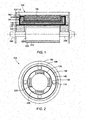
- Fig. 1 shows a superconducting electrical machine 100.
- the superconducting electrical machine 100 may have an air gap design 105.
- the superconducting electrical machine 100 includes a high temperature superconducting armature coil 110.
- the high temperature superconducting armature coil may be made out of a high temperature superconducting material 120.
- the high temperature superconducting materials 120 may include, by way of example only, bismuth-strontium-calcium-copper-oxygen compounds such as BSCCO-2223 (Bi 2 Sr 2 Ca 2 Cu 3 0 1o ), BSCCO-2212 (Bi 2 Sr 2 Ca 1 Cu 2 O 8 ), TlBa 2 Ca 2 Cu 3 O 9 , T1 2 Ba 2 CaCu 2 O 8 , (TlPb)Sr 2 CaCu 2 O 7 , (TIPb)Sr 2 Ca 2 CuO 9 ; yttrium barium copper oxide (YBa 2 Cu 3 O 7 and referred to as YBCO); magnesium diboride (MgB 2 ); and combinations thereof.
- BSCCO-2223 Bi 2 Sr 2 Ca 2 Cu 3 0 1o
- BSCCO-2212 Bi 2 Sr 2 Ca 1 Cu 2 O 8
- TlBa 2 Ca 2 Cu 3 O 9 T1 2 Ba 2 CaCu 2 O 8
- TlPb Sr 2 CaCu 2
- a high temperature superconducting cooling system 130 also may be used herein.
- the high temperature superconducting cooling system 130 may be positioned about the high temperature superconducting armature coil 110 so as to maintain the high temperature superconducting armature coil 110 within the desired operating temperature range.
- the high temperature superconducting cooling system 130 may include a cryostat 140 with a volume of liquid nitrogen 150 therein. Other types of cryogenic fluids and the like may be used herein. An external cyrocooler (not shown) may be used so as to chill the liquid nitrogen 150 or other types of fluids to the appropriate temperature.
- the cryostat 140 may be made out of composite materials.
- the cryostat 140 may be attached to a support frame 160 of the overall electrical machine 100 via a number of torque tubes 170.
- the torque tubes 170 may be made out of a high strength alloy, such as a titanium alloy and the like, so as to support the large torque generally experienced by the high temperature superconducting armature coil 110. Other components and other configuration
- the high temperature superconducting cooling system 130 further may include a foam insulation 190.
- the foam insulation 190 may be applied between the cryostat 140 and the support frame 160.
- the foam insulation 190 may be used to reduce the heat load therein without requiring the use of conventional vacuum insulation and the like. Any type of conventional insulation may be used herein.
- the superconducting electrical machine 100 further may include an iron yoke 180 positioned about the high temperature superconducting armature coil 110.
- the iron yoke 180 contains the magnetic flux therein.
- Other components and other configurations may be used herein.
- the superconducting electrical machine 100 also may include a superconducting field coil 200.
- the superconducting field coil 200 may be made out of a superconducting material 210.
- the superconducting materials 210 may include the high temperature superconducting materials 120 described above as well as various types of low temperature superconducting materials such as niobium-titanium (NbTi), Niobium-tin (Nb 3 Sn), combinations thereof, and the like.
- the superconducting field coil 200 may be positioned about a rotor 220 for rotation therewith.
- the rotor 220 may be positioned about a shaft 230.
- the shaft 230 may extend out of the support frame 160.
- a cryogen transfer coupling 240 may be used.
- the cryogenic transfer coupling 240 may be positioned about the shaft 230 so as to provide liquid nitrogen or other type of cryogenic fluid to cool the superconducting field coil 200.
- Other components and other configurations may be used herein.
- Figs. 3 and 4 show an alternative embodiment of a superconducting electric machine 250 with a high temperature superconducting cooling system 260.
- this example has a liquid nitrogen cooling tube 270 positioned between each coil bar 280 of a high temperature superconducting armature coil 290.
- Each coil bar 280 may be made out of a high temperature superconducting tape 300.
- the high temperature superconducting tape 300 may be a YBCO-type tape or other type of high temperature superconducting material 120.
- the liquid nitrogen cooling tube 270 may extend into a cooling pad 310 about an end winding area 320 of each of the coil bars 280.
- the liquid nitrogen 150 thus may flow from an inlet manifold 330 to an outlet manifold 340 so as to cool the entire high temperature superconducting armature coil 290.
- Other types of high temperature superconducting cooling systems 260 may be used herein with other components and other configurations.
- the high temperature superconducting armature coil 110 of the air gap electrical machine 105 may be directly exposed to a strong magnetic field.
- Use of the high temperature superconducting material 120 limits alternating current losses such that the high temperature superconducting armature coil 110 may be adequately cooled via the high temperature superconducting cooling system 130.
- the high temperature superconducting cooling system 130 may be simplified with the use of the foam insulation 190 given that the system heat load is negligible as compared to the alternating current losses.
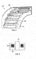
- Figs. 5 and 6 show an alternative embodiment of a superconducting electrical machine 350.
- the superconducting electrical machine 350 may be a tooth-wound electrical machine 360.
- the tooth-wound electrical machine 360 may include a number of iron teeth 370.
- a high temperature superconducting armature coil 380 may be wound about each of the iron teeth 370.
- the high temperature superconducting armature coils 380 may be made out of the high temperature superconducting materials 120 described above and the like.
- Each of the high temperature superconducting armature coils 380 may be positioned in a vacuum insulated cryostat 390.
- the vacuum insulated cryostat 390 may be bonded to the iron tooth 370.
- Other types of cooling systems may be used herein.
- Liquid nitrogen 150 or other types of cryogenic fluids may be positioned therein so as to cool the high temperature superconducting armature coils 380.
- Other components and other configurations may be used herein.
- the magnetic field may be significantly reduced by concentrating the magnetic flux in the iron teeth 370 of the tooth wound electrical machine 360. As a result, the total alternating current losses induced in the high temperature superconducting armature coils 380 may be reduced.
- the air gap design 105 thus provides the highest potential torque density and weight reduction. Due to the large alternating current magnetic field, there are alternating current losses.
- the high temperature superconducting cooling system 130 is very simple given the use of the foam insulation 190.
- the tooth wound design 360 reintroduces the use of the iron teeth 370 and the overall weight thereof.
- the high temperature superconducting cooling system 130 also may be somewhat more complicated in the tooth-wound design 360 given the use of the vacuum insulated cryostat 390.
- the alternating current losses from the high temperature superconducting armature coils 380 are greatly reduced.
- overall power density herein thus may be improved by a factor of about two to five or more by the use of the high temperature superconducting material 120 in the high temperature superconducting armature coils 110, 380. Moreover, the power density may be improved further through the use of the superconducting materials 120 for the superconducting field coil 200.
- the electrical machines described herein thus may be compact and light weight. Potential applications include low speed machines such as direct drive wind turbines, especially for high power rating offshore generators, electrical ship propulsion systems, and the like.
Landscapes
- Engineering & Computer Science (AREA)
- Power Engineering (AREA)
- Superconductive Dynamoelectric Machines (AREA)
Abstract
Description
- The present application relates generally to electrical machines and more particularly relate to superconducting electrical machines with armature winding coils and other components made from a high temperature superconducting material.
- Generally described, typical electrical machines such as motors and generators include a field coil mounted about a rotor and armature winding coils mounted about a stator. Once a voltage is applied, a magnetic field couples the field coil and the armature winding coils. The magnitude of the magnetic field depends upon the amount of current passing through the field coil. The magnetic stress within the electrical machine translates to torque so as to result in the rotation of the rotor. The higher the magnetic field, the greater the torque per rotation for a given circumference of the armature winding coils.
- Using field coils made from a superconducting material makes the electrical machine more compact, light weight, and efficient due to the increased magnetic field strength caused by the superconducting material. Overall electrical machine performance also may be improved by increasing the current carrying capacity of the armature winding coils. Replacing the original copper coils with coils made from a superconducting material thus may significantly increase the overall power density by a factor of about two to five or more.
- One issue with the use of known superconducting materials, however, includes excessive alternating current losses induced by the exposure to a strong alternative magnetic field. Although certain types of high temperature superconducting materials generally have lower alternating current losses, adequate and somewhat complicated cooling systems must be provided to maintain the superconducting material within the desired operating temperature range. Moreover, different design and operational issues may be found with air gap based coils and with tooth-wound coils and the like.
- There is therefore a desire for an improved electrical machine using high temperature superconducting materials for either air gap or tooth-wound coil designs. Such improved electrical machine designs preferably may avoid large alternating current losses while providing a simplified cooling system. Moreover, such improved designs preferably should provide a lightweight and compact shape with high operational efficiency.
- The present application thus describes a superconducting electrical machine. The superconducting electrical machine may include an armature coil made of a high temperature superconducting material, a cooling system, and a field coil. The cooling system may include a cryostat surrounding the armature coil and a foam insulation surrounding the cryostat.
- The present application further provides a superconducting electrical machine. The superconducting electrical machine described herein may include an armature coil surrounding an iron tooth, a cooling system, and a field coil. The armature coil may be made out of a high temperature superconducting material. The cooling system may include a vacuum insulated cryostat bonded to the iron tooth.
- The present application further provides a superconducting electrical machine. The superconducting electrical machine may include an armature coil in an air gap configuration, a cooling system, and a field coil. The armature coil may be made out of a high temperature superconducting material. The cooling system may include a foam insulation surrounding the armature coil.
- Various features and improvements of the present invention will become apparent to one of ordinary skill in the art upon review of the following detailed description when taken in conjunction with the several drawings and the appended claims. In the drawings:
-
Fig. 1 is a schematic view of a superconducting electrical machine according to an embodiment of the present invention. -
Fig. 2 is a cross-sectional view of the superconducting electrical machine ofFig. 1 . -
Fig. 3 is perspective view of an alternative embodiment of a superconducting electrical machine. -
Fig. 4 is a side cross-sectional view of the superconducting electrical machine ofFig. 3 . -
Fig. 5 is a partial perspective view of an alternative embodiment of a superconducting electrical machine. -
Fig. 6 is a cross-sectional view of a portion of the superconducting electrical machine ofFig. 5 . - Referring now to the drawings, in which like numerals relate to like elements throughout the several views,
Fig. 1 shows a superconductingelectrical machine 100. In this example, the superconductingelectrical machine 100 may have anair gap design 105. The superconductingelectrical machine 100 includes a high temperaturesuperconducting armature coil 110. The high temperature superconducting armature coil may be made out of a high temperaturesuperconducting material 120. The high temperaturesuperconducting materials 120 may include, by way of example only, bismuth-strontium-calcium-copper-oxygen compounds such as BSCCO-2223 (Bi2Sr2Ca2Cu301o), BSCCO-2212 (Bi2Sr2Ca1Cu2O8), TlBa2Ca2Cu3O9, T12Ba2CaCu2O8, (TlPb)Sr2CaCu2O7, (TIPb)Sr2Ca2CuO9; yttrium barium copper oxide (YBa2Cu3O7 and referred to as YBCO); magnesium diboride (MgB2); and combinations thereof. Other types of high temperaturesuperconducting materials 120 and combinations thereof may be used herein. - A high temperature
superconducting cooling system 130 also may be used herein. The high temperaturesuperconducting cooling system 130 may be positioned about the high temperaturesuperconducting armature coil 110 so as to maintain the high temperaturesuperconducting armature coil 110 within the desired operating temperature range. The high temperaturesuperconducting cooling system 130 may include acryostat 140 with a volume ofliquid nitrogen 150 therein. Other types of cryogenic fluids and the like may be used herein. An external cyrocooler (not shown) may be used so as to chill theliquid nitrogen 150 or other types of fluids to the appropriate temperature. Thecryostat 140 may be made out of composite materials. Thecryostat 140 may be attached to asupport frame 160 of the overallelectrical machine 100 via a number oftorque tubes 170. Thetorque tubes 170 may be made out of a high strength alloy, such as a titanium alloy and the like, so as to support the large torque generally experienced by the high temperaturesuperconducting armature coil 110. Other components and other configurations may be used herein. - The high temperature
superconducting cooling system 130 further may include afoam insulation 190. Thefoam insulation 190 may be applied between thecryostat 140 and thesupport frame 160. Thefoam insulation 190 may be used to reduce the heat load therein without requiring the use of conventional vacuum insulation and the like. Any type of conventional insulation may be used herein. - The superconducting
electrical machine 100 further may include aniron yoke 180 positioned about the high temperaturesuperconducting armature coil 110. Theiron yoke 180 contains the magnetic flux therein. Other components and other configurations may be used herein. - The superconducting
electrical machine 100 also may include asuperconducting field coil 200. Thesuperconducting field coil 200 may be made out of asuperconducting material 210. Thesuperconducting materials 210 may include the high temperaturesuperconducting materials 120 described above as well as various types of low temperature superconducting materials such as niobium-titanium (NbTi), Niobium-tin (Nb3Sn), combinations thereof, and the like. Thesuperconducting field coil 200 may be positioned about arotor 220 for rotation therewith. Therotor 220 may be positioned about ashaft 230. Theshaft 230 may extend out of thesupport frame 160. - In order to cool the
superconducting field coil 200, acryogen transfer coupling 240 may be used. Thecryogenic transfer coupling 240 may be positioned about theshaft 230 so as to provide liquid nitrogen or other type of cryogenic fluid to cool thesuperconducting field coil 200. Other components and other configurations may be used herein. -
Figs. 3 and 4 show an alternative embodiment of a superconductingelectric machine 250 with a high temperaturesuperconducting cooling system 260. Instead of the use of thecryostat 140, this example has a liquidnitrogen cooling tube 270 positioned between eachcoil bar 280 of a high temperaturesuperconducting armature coil 290. - Each
coil bar 280 may be made out of a hightemperature superconducting tape 300. The hightemperature superconducting tape 300 may be a YBCO-type tape or other type of hightemperature superconducting material 120. The liquidnitrogen cooling tube 270 may extend into acooling pad 310 about anend winding area 320 of each of the coil bars 280. Theliquid nitrogen 150 thus may flow from aninlet manifold 330 to anoutlet manifold 340 so as to cool the entire high temperaturesuperconducting armature coil 290. Other types of high temperaturesuperconducting cooling systems 260 may be used herein with other components and other configurations. - In use, the high temperature
superconducting armature coil 110 of the air gapelectrical machine 105 may be directly exposed to a strong magnetic field. Use of the hightemperature superconducting material 120, however, limits alternating current losses such that the high temperaturesuperconducting armature coil 110 may be adequately cooled via the high temperaturesuperconducting cooling system 130. Moreover, the high temperaturesuperconducting cooling system 130 may be simplified with the use of thefoam insulation 190 given that the system heat load is negligible as compared to the alternating current losses. -
Figs. 5 and 6 show an alternative embodiment of a superconductingelectrical machine 350. In this example, the superconductingelectrical machine 350 may be a tooth-woundelectrical machine 360. The tooth-woundelectrical machine 360 may include a number ofiron teeth 370. A high temperaturesuperconducting armature coil 380 may be wound about each of theiron teeth 370. The high temperature superconducting armature coils 380 may be made out of the hightemperature superconducting materials 120 described above and the like. Each of the high temperature superconducting armature coils 380 may be positioned in a vacuum insulatedcryostat 390. The vacuum insulatedcryostat 390 may be bonded to theiron tooth 370. Other types of cooling systems may be used herein.Liquid nitrogen 150 or other types of cryogenic fluids may be positioned therein so as to cool the high temperature superconducting armature coils 380. Other components and other configurations may be used herein. - In use, the magnetic field may be significantly reduced by concentrating the magnetic flux in the
iron teeth 370 of the tooth woundelectrical machine 360. As a result, the total alternating current losses induced in the high temperature superconducting armature coils 380 may be reduced. - The
air gap design 105 thus provides the highest potential torque density and weight reduction. Due to the large alternating current magnetic field, there are alternating current losses. The high temperaturesuperconducting cooling system 130, however, is very simple given the use of thefoam insulation 190. Conversely, thetooth wound design 360 reintroduces the use of theiron teeth 370 and the overall weight thereof. The high temperaturesuperconducting cooling system 130 also may be somewhat more complicated in the tooth-wound design 360 given the use of the vacuum insulatedcryostat 390. The alternating current losses from the high temperature superconducting armature coils 380, however, are greatly reduced. - In either design, overall power density herein thus may be improved by a factor of about two to five or more by the use of the high
temperature superconducting material 120 in the high temperature superconducting armature coils 110, 380. Moreover, the power density may be improved further through the use of thesuperconducting materials 120 for thesuperconducting field coil 200. The electrical machines described herein thus may be compact and light weight. Potential applications include low speed machines such as direct drive wind turbines, especially for high power rating offshore generators, electrical ship propulsion systems, and the like. - It should be apparent that the foregoing relates only to certain embodiments of the present application and the resultant patent. Numerous changes and modifications may be made herein by one of ordinary skill in the art without departing from the general spirit and scope of the invention as defmed by the following claims and the equivalents thereof.
- Various aspects and embodiments of the present invention are defined by the following numbered clauses:
- 1. A superconducting electrical machine, comprising:
- an armature coil;
- the armature coil comprising a high temperature superconducting material;
- a cooling system;
- the cooling system comprises a cryostat surrounding the armature coil and a foam insulation surrounding the cryostat; and
- a field coil.
- 2. The superconducting electrical machine of clause 1, wherein the armature coil comprises an air gap design.
- 3. The superconducting electrical machine of any preceding clause, wherein the high temperature superconducting material comprises bismuth-strontium-calcium-copper-oxygen compounds, yttrium barium copper oxide, magnesium diboride, and/or combinations thereof.
- 4. The superconducting electrical machine of any preceding clause, wherein the cryostat is attached to a frame by one or more torque tubes.
- 5. The superconducting electrical machine of any preceding clause, wherein the field coil comprises a superconducting material.
- 6. The superconducting electrical machine of any preceding clause, wherein the superconducting material of the field coil comprises the high temperature superconducting material.
- 7. The superconducting electrical machine of any preceding clause, wherein the cooling system comprises a cryogen transfer coupling positioned about the field coil.
- 8. The superconducting electrical machine of any preceding clause, wherein the armature coil comprises a plurality of coil bars and wherein the cooling system comprises a cooling tube positioned between each of the plurality of coil bars.
- 9. The superconducting electrical machine of any preceding clause, wherein the cooling system comprises a plurality of cooling pads extending from the plurality of cooling tubes.
- 10. The superconducting electrical machine of any preceding clause, wherein the plurality of coil bars comprises a high temperature superconducting tape.
- 11. A superconducting electrical machine, comprising:
- an armature coil surrounding an iron tooth;
- the armature coil comprising a high temperature superconducting material;
- a cooling system;
- the cooling system comprising a vacuum insulated cryostat bonded to the iron tooth; and
- a field coil.
- 12. The superconducting electrical machine of any preceding clause, wherein the high temperature superconducting material comprises bismuth-strontium-calcium-copper-oxygen compounds, yttrium barium copper oxide, magnesium diboride, and/or combinations thereof.
- 13. The superconducting electrical machine of any preceding clause, further comprising a plurality of armature coils surrounding a plurality of iron teeth.
- 14. The superconducting electrical machine of any preceding clause, further comprising a plurality of vacuum insulated cryostat bonded to the plurality of iron teeth.
- 15. The superconducting electrical machine of any preceding clause, wherein the vacuum insulated cryostat comprises liquid nitrogen therein.
- 16. A superconducting electrical machine, comprising:
- an armature coil;
- the armature coil comprising an air gap configuration;
- the armature coil comprising a high temperature superconducting material;
- a cooling system;
- the cooling system comprising a foam insulation surrounding the armature coil;
and - a field coil.
- 17. The superconducting electrical machine of any preceding clause, wherein the high temperature superconducting material comprises bismuth-strontium-calcium-copper-oxygen compounds, yttrium barium copper oxide, magnesium diboride, and/or combinations thereof.
- 18. The superconducting electrical machine of any preceding clause, wherein the cooling system comprises a cryostat surrounding the armature coil.
- 19. The superconducting electrical machine of any preceding clause, wherein the field coil comprises a superconducting material.
- 20. The superconducting electrical machine of any preceding clause, wherein the cooling system comprises a cryogen transfer coupling positioned about the field coil.
Claims (10)
- A superconducting electrical machine (100), comprising:an armature coil (110);the armature coil comprising a high temperature superconducting material (120);a cooling system (130);the cooling system (130) comprises a cryostat (140) surrounding the armature coil (110) and a foam insulation (190) surrounding the cryostat (140); anda field coil (200).
- The superconducting electrical machine (100) of claim 1, wherein the armature coil (110) comprises an air gap design (105).
- The superconducting electrical machine (100) of any preceding claim, wherein the high temperature superconducting material (120) comprises bismuth-strontium-calcium-copper-oxygen compounds, yttrium barium copper oxide, magnesium diboride, and/or combinations thereof.
- The superconducting electrical machine (100) of any preceding claim, wherein the cryostat (140) is attached to a frame (160) by one or more torque tubes (170).
- The superconducting electrical machine (100) of any preceding claim, wherein the field coil (200) comprises a superconducting material (210).
- The superconducting electrical machine (100) of claim 5, wherein the superconducting material (210) comprises the high temperature superconducting material (120).
- The superconducting electrical machine (100) of any preceding claim, wherein the cooling system (130) comprises a cryogenic transfer coupling (240) positioned about the field coil (200).
- The superconducting electrical machine (100) of any preceding claim, wherein the armature coil (100) comprises a plurality of coil bars (280) and wherein the cooling system (130) comprises a cooling tube (270) positioned between each of the plurality of coil bars (280).
- The superconducting electrical machine (100) of claim 8, wherein the cooling system (130) comprises a plurality of cooling pads (310) extending from the plurality of cooling tubes (270).
- The superconducting electrical machine (100) of claim 8 or claim 9, wherein the plurality of coil bars (280) comprises a high temperature superconducting tape (300).
Applications Claiming Priority (1)
| Application Number | Priority Date | Filing Date | Title |
|---|---|---|---|
| US13/094,853 US8436499B2 (en) | 2011-04-27 | 2011-04-27 | Electrical machine with superconducting armature coils and other components |
Publications (2)
| Publication Number | Publication Date |
|---|---|
| EP2518872A2 true EP2518872A2 (en) | 2012-10-31 |
| EP2518872A3 EP2518872A3 (en) | 2017-04-19 |
Family
ID=44971919
Family Applications (1)
| Application Number | Title | Priority Date | Filing Date |
|---|---|---|---|
| EP12164648.3A Withdrawn EP2518872A3 (en) | 2011-04-27 | 2012-04-18 | Electrical machine with superconducting armature coils and other components |
Country Status (3)
| Country | Link |
|---|---|
| US (1) | US8436499B2 (en) |
| EP (1) | EP2518872A3 (en) |
| CN (1) | CN102780382B (en) |
Families Citing this family (14)
| Publication number | Priority date | Publication date | Assignee | Title |
|---|---|---|---|---|
| DE102011082652B4 (en) * | 2011-09-14 | 2013-08-01 | Bruker Biospin Ag | Method for producing a magnet coil arrangement from a slotted strip-shaped conductor and magnet coil arrangement |
| AR083135A1 (en) * | 2011-10-05 | 2013-02-06 | Ind Metalurgicas Pescarmona S A I C Y F | SYNCHRONIC WIND GENERATOR |
| DE102011056008A1 (en) | 2011-12-02 | 2013-06-06 | Oswald Elektromotoren Gmbh | Electric machine |
| EP3078104B1 (en) * | 2013-12-04 | 2018-10-17 | Hyper Tech Research, Inc. | Superconducting generators and motors |
| US20160322143A1 (en) * | 2013-12-18 | 2016-11-03 | Victoria Link Limited | Cryostat for Superconducting Devices |
| ES2656821B1 (en) * | 2016-08-30 | 2018-12-04 | Siemens Gamesa Renewable Energy Innovation & Technology, S.L. | Synchronous generator for wind turbines |
| US10601299B2 (en) * | 2017-09-07 | 2020-03-24 | American Superconductor Corporation | High temperature superconductor generator with increased rotational inertia |
| EP3518399B1 (en) * | 2018-01-30 | 2020-09-30 | Siemens Gamesa Renewable Energy A/S | A cooling system for a superconducting generator |
| DE102018205361A1 (en) * | 2018-04-10 | 2019-10-10 | Siemens Aktiengesellschaft | Rotor with winding carrier and coil element embedded therein |
| EP3804108A4 (en) * | 2018-06-01 | 2022-01-19 | General Electric Company | PARTIAL CRYOGENIC SHIELD ASSEMBLY IN A SUPERCONDUCTIVE GENERATOR AND METHODS OF ASSEMBLING THE SAME |
| EP3609060A1 (en) * | 2018-08-08 | 2020-02-12 | Siemens Gamesa Renewable Energy A/S | Generator having superconducting coil windings |
| CN113316886B (en) * | 2018-11-21 | 2024-08-23 | 通用电气可再生能源西班牙有限公司 | Superconducting generator driven by wind turbine |
| JP6899022B1 (en) * | 2020-04-27 | 2021-07-07 | 大倉 健吾 | Motor device |
| EP4024672A1 (en) * | 2020-12-30 | 2022-07-06 | General Electric Renovables España S.L. | Armature segment, armature and methods for assembling them |
Family Cites Families (22)
| Publication number | Priority date | Publication date | Assignee | Title |
|---|---|---|---|---|
| US4058746A (en) * | 1973-01-29 | 1977-11-15 | Westinghouse Electric Corporation | Dynamoelectric machinery utilizing superconductive windings |
| FR2605158B1 (en) * | 1986-09-25 | 1993-08-20 | Alsthom | SUPERCONDUCTING ROTATING ELECTRIC MACHINE AND ITS THERMAL ISOLATION |
| JPH01144356A (en) | 1987-11-30 | 1989-06-06 | Toshiba Corp | Superconducting electric rotary machine |
| US5289150A (en) * | 1991-08-30 | 1994-02-22 | Electric Power Research Institute | Method and apparatus for superconducting trapped-field energy storage and power stabilization |
| JP3464252B2 (en) | 1993-09-15 | 2003-11-05 | 株式会社イムラ材料開発研究所 | Superconducting motor |
| US5777420A (en) | 1996-07-16 | 1998-07-07 | American Superconductor Corporation | Superconducting synchronous motor construction |
| US6376943B1 (en) | 1998-08-26 | 2002-04-23 | American Superconductor Corporation | Superconductor rotor cooling system |
| US6278212B1 (en) | 1999-07-07 | 2001-08-21 | American Superconductor Corp. | Exciter with axial gap |
| US6489701B1 (en) | 1999-10-12 | 2002-12-03 | American Superconductor Corporation | Superconducting rotating machines |
| US6347522B1 (en) | 2000-01-11 | 2002-02-19 | American Superconductor Corporation | Cooling system for HTS machines |
| US6674206B2 (en) * | 2000-01-11 | 2004-01-06 | American Superconductor Corporation | Tangential torque support |
| US6359365B1 (en) | 2000-08-04 | 2002-03-19 | American Superconductor Corporation | Superconducting synchronous machine field winding protection |
| DE10042962C1 (en) * | 2000-08-31 | 2002-05-02 | Siemens Ag | Magnetic bearing to support a rotatable shaft using high-T¶c¶ superconductor material |
| DE10231434A1 (en) * | 2002-05-15 | 2003-12-04 | Siemens Ag | Superconductive device has rotor winding incorporated in refrigerated winding support coupled to refrigeration head |
| CN2558154Y (en) | 2002-08-12 | 2003-06-25 | 郑双慧 | Superconductive magnetic power composite type generator and motor |
| US7088020B2 (en) * | 2003-03-26 | 2006-08-08 | Siemens Power Generation, Inc. | Apparatus and method for consolidating conductive strands of a stator coil |
| GB2417140B (en) * | 2004-08-09 | 2008-01-23 | Alstom | Rotating superconducting machines |
| JP4661263B2 (en) * | 2005-02-23 | 2011-03-30 | 住友電気工業株式会社 | Superconducting motor device |
| US7233079B1 (en) | 2005-10-18 | 2007-06-19 | Willard Cooper | Renewable energy electric power generating system |
| US7566684B1 (en) * | 2006-08-24 | 2009-07-28 | The United States Of America As Represented By The Secretary Of The Air Force | Machinery windings of yttrium barium copper oxide and related coated conductor |
| US8204562B2 (en) | 2007-10-02 | 2012-06-19 | Korea Electrotechnology Research Institute | Superconducting synchronous machine |
| US8346326B2 (en) | 2008-01-17 | 2013-01-01 | General Electric Company | Superconductive wire, processes of manufacture and uses thereof |
-
2011
- 2011-04-27 US US13/094,853 patent/US8436499B2/en active Active
-
2012
- 2012-04-18 EP EP12164648.3A patent/EP2518872A3/en not_active Withdrawn
- 2012-04-27 CN CN201210143283.6A patent/CN102780382B/en active Active
Non-Patent Citations (1)
| Title |
|---|
| None |
Also Published As
| Publication number | Publication date |
|---|---|
| EP2518872A3 (en) | 2017-04-19 |
| CN102780382B (en) | 2017-06-09 |
| US20110285219A1 (en) | 2011-11-24 |
| US8436499B2 (en) | 2013-05-07 |
| CN102780382A (en) | 2012-11-14 |
Similar Documents
| Publication | Publication Date | Title |
|---|---|---|
| US8436499B2 (en) | Electrical machine with superconducting armature coils and other components | |
| US7489060B2 (en) | Superconducting rotating machines with stationary field coils | |
| US6066906A (en) | Rotating machine having superconducting windings | |
| US8212437B2 (en) | Superconducting multi-pole electrical machine | |
| CN109716636B (en) | Rotor with coil arrangement and winding support | |
| US7492073B2 (en) | Superconducting rotating machines with stationary field coils | |
| JP5448296B2 (en) | Tubular electrical machine | |
| EP1794871A1 (en) | Superconducting electrical machine | |
| CN108370211B (en) | Synchronous superconducting rotary machine with continuous pole configuration | |
| CN103151875B (en) | Wind turbine with sealed off stator chamber | |
| US11303194B1 (en) | Wound field synchronous machine | |
| EP2831987B1 (en) | Wide electrical conductor having high c-axis strength | |
| US20140009014A1 (en) | Direct-drive superconducting synchronous generator for a wind turbine | |
| CN103166426B (en) | Superconducting generator | |
| Keysan | Application of high-temperature superconducting machines to direct drive renewable energy systems | |
| RU2761864C1 (en) | Synchronous superconducting wind generator | |
| Al-Mosawi et al. | Development of a coreless HTS synchronous generator operating at sub-cooled liquid nitrogen temperatures | |
| Al-Mosawi et al. | 100kVA high temperature superconducting generator | |
| Miki et al. | Applied HTS Bulks and Wires to Rotating Machines for Marine Propulsion |
Legal Events
| Date | Code | Title | Description |
|---|---|---|---|
| PUAI | Public reference made under article 153(3) epc to a published international application that has entered the european phase |
Free format text: ORIGINAL CODE: 0009012 |
|
| AK | Designated contracting states |
Kind code of ref document: A2 Designated state(s): AL AT BE BG CH CY CZ DE DK EE ES FI FR GB GR HR HU IE IS IT LI LT LU LV MC MK MT NL NO PL PT RO RS SE SI SK SM TR |
|
| AX | Request for extension of the european patent |
Extension state: BA ME |
|
| PUAL | Search report despatched |
Free format text: ORIGINAL CODE: 0009013 |
|
| AK | Designated contracting states |
Kind code of ref document: A3 Designated state(s): AL AT BE BG CH CY CZ DE DK EE ES FI FR GB GR HR HU IE IS IT LI LT LU LV MC MK MT NL NO PL PT RO RS SE SI SK SM TR |
|
| AX | Request for extension of the european patent |
Extension state: BA ME |
|
| RIC1 | Information provided on ipc code assigned before grant |
Ipc: H02K 55/02 20060101ALN20170314BHEP Ipc: H02K 55/04 20060101AFI20170314BHEP |
|
| STAA | Information on the status of an ep patent application or granted ep patent |
Free format text: STATUS: REQUEST FOR EXAMINATION WAS MADE |
|
| 17P | Request for examination filed |
Effective date: 20171019 |
|
| RBV | Designated contracting states (corrected) |
Designated state(s): AL AT BE BG CH CY CZ DE DK EE ES FI FR GB GR HR HU IE IS IT LI LT LU LV MC MK MT NL NO PL PT RO RS SE SI SK SM TR |
|
| STAA | Information on the status of an ep patent application or granted ep patent |
Free format text: STATUS: EXAMINATION IS IN PROGRESS |
|
| 17Q | First examination report despatched |
Effective date: 20190709 |
|
| GRAP | Despatch of communication of intention to grant a patent |
Free format text: ORIGINAL CODE: EPIDOSNIGR1 |
|
| STAA | Information on the status of an ep patent application or granted ep patent |
Free format text: STATUS: GRANT OF PATENT IS INTENDED |
|
| RIC1 | Information provided on ipc code assigned before grant |
Ipc: H02K 55/02 20060101ALN20200421BHEP Ipc: H02K 55/04 20060101AFI20200421BHEP |
|
| INTG | Intention to grant announced |
Effective date: 20200512 |
|
| RIC1 | Information provided on ipc code assigned before grant |
Ipc: H02K 55/02 20060101ALN20200427BHEP Ipc: H02K 55/04 20060101AFI20200427BHEP |
|
| STAA | Information on the status of an ep patent application or granted ep patent |
Free format text: STATUS: THE APPLICATION IS DEEMED TO BE WITHDRAWN |
|
| 18D | Application deemed to be withdrawn |
Effective date: 20200923 |
|
| P01 | Opt-out of the competence of the unified patent court (upc) registered |
Effective date: 20230530 |