EP2518859A2 - Power supply device - Google Patents
Power supply device Download PDFInfo
- Publication number
- EP2518859A2 EP2518859A2 EP12165300A EP12165300A EP2518859A2 EP 2518859 A2 EP2518859 A2 EP 2518859A2 EP 12165300 A EP12165300 A EP 12165300A EP 12165300 A EP12165300 A EP 12165300A EP 2518859 A2 EP2518859 A2 EP 2518859A2
- Authority
- EP
- European Patent Office
- Prior art keywords
- power supply
- units
- precharge
- supply device
- battery units
- Prior art date
- Legal status (The legal status is an assumption and is not a legal conclusion. Google has not performed a legal analysis and makes no representation as to the accuracy of the status listed.)
- Granted
Links
Images


Classifications
-
- H—ELECTRICITY
- H02—GENERATION; CONVERSION OR DISTRIBUTION OF ELECTRIC POWER
- H02J—ELECTRIC POWER NETWORKS; CIRCUIT ARRANGEMENTS OR SYSTEMS FOR SUPPLYING OR DISTRIBUTING ELECTRIC POWER; SYSTEMS FOR STORING ELECTRIC ENERGY
- H02J7/00—Circuit arrangements for charging or discharging batteries or for supplying loads from batteries
- H02J7/50—Circuit arrangements for charging or discharging batteries or for supplying loads from batteries acting upon multiple batteries simultaneously or sequentially
- H02J7/52—Circuit arrangements for charging or discharging batteries or for supplying loads from batteries acting upon multiple batteries simultaneously or sequentially for charge balancing, e.g. equalisation of charge between batteries
- H02J7/54—Passive balancing, e.g. using resistors or parallel MOSFETs
-
- H—ELECTRICITY
- H01—ELECTRIC ELEMENTS
- H01M—PROCESSES OR MEANS, e.g. BATTERIES, FOR THE DIRECT CONVERSION OF CHEMICAL ENERGY INTO ELECTRICAL ENERGY
- H01M10/00—Secondary cells; Manufacture thereof
- H01M10/42—Methods or arrangements for servicing or maintenance of secondary cells or secondary half-cells
- H01M10/4207—Methods or arrangements for servicing or maintenance of secondary cells or secondary half-cells for several batteries or cells simultaneously or sequentially
-
- H—ELECTRICITY
- H01—ELECTRIC ELEMENTS
- H01M—PROCESSES OR MEANS, e.g. BATTERIES, FOR THE DIRECT CONVERSION OF CHEMICAL ENERGY INTO ELECTRICAL ENERGY
- H01M10/00—Secondary cells; Manufacture thereof
- H01M10/42—Methods or arrangements for servicing or maintenance of secondary cells or secondary half-cells
- H01M10/425—Structural combination with electronic components, e.g. electronic circuits integrated to the outside of the casing
-
- H—ELECTRICITY
- H01—ELECTRIC ELEMENTS
- H01M—PROCESSES OR MEANS, e.g. BATTERIES, FOR THE DIRECT CONVERSION OF CHEMICAL ENERGY INTO ELECTRICAL ENERGY
- H01M10/00—Secondary cells; Manufacture thereof
- H01M10/42—Methods or arrangements for servicing or maintenance of secondary cells or secondary half-cells
- H01M10/46—Accumulators structurally combined with charging apparatus
-
- H—ELECTRICITY
- H01—ELECTRIC ELEMENTS
- H01M—PROCESSES OR MEANS, e.g. BATTERIES, FOR THE DIRECT CONVERSION OF CHEMICAL ENERGY INTO ELECTRICAL ENERGY
- H01M10/00—Secondary cells; Manufacture thereof
- H01M10/42—Methods or arrangements for servicing or maintenance of secondary cells or secondary half-cells
- H01M10/48—Accumulators combined with arrangements for measuring, testing or indicating the condition of cells, e.g. the level or density of the electrolyte
- H01M10/482—Accumulators combined with arrangements for measuring, testing or indicating the condition of cells, e.g. the level or density of the electrolyte for several batteries or cells simultaneously or sequentially
-
- H—ELECTRICITY
- H01—ELECTRIC ELEMENTS
- H01M—PROCESSES OR MEANS, e.g. BATTERIES, FOR THE DIRECT CONVERSION OF CHEMICAL ENERGY INTO ELECTRICAL ENERGY
- H01M50/00—Constructional details or processes of manufacture of the non-active parts of electrochemical cells other than fuel cells, e.g. hybrid cells
- H01M50/50—Current conducting connections for cells or batteries
- H01M50/572—Means for preventing undesired use or discharge
- H01M50/574—Devices or arrangements for the interruption of current
-
- H—ELECTRICITY
- H02—GENERATION; CONVERSION OR DISTRIBUTION OF ELECTRIC POWER
- H02J—ELECTRIC POWER NETWORKS; CIRCUIT ARRANGEMENTS OR SYSTEMS FOR SUPPLYING OR DISTRIBUTING ELECTRIC POWER; SYSTEMS FOR STORING ELECTRIC ENERGY
- H02J7/00—Circuit arrangements for charging or discharging batteries or for supplying loads from batteries
- H02J7/60—Circuit arrangements for charging or discharging batteries or for supplying loads from batteries including safety or protection arrangements
- H02J7/663—Circuit arrangements for charging or discharging batteries or for supplying loads from batteries including safety or protection arrangements using battery or load disconnect circuits
-
- G—PHYSICS
- G01—MEASURING; TESTING
- G01R—MEASURING ELECTRIC VARIABLES; MEASURING MAGNETIC VARIABLES
- G01R31/00—Arrangements for testing electric properties; Arrangements for locating electric faults; Arrangements for electrical testing characterised by what is being tested not provided for elsewhere
- G01R31/36—Arrangements for testing, measuring or monitoring the electrical condition of accumulators or electric batteries, e.g. capacity or state of charge [SoC]
- G01R31/396—Acquisition or processing of data for testing or for monitoring individual cells or groups of cells within a battery
-
- H—ELECTRICITY
- H01—ELECTRIC ELEMENTS
- H01M—PROCESSES OR MEANS, e.g. BATTERIES, FOR THE DIRECT CONVERSION OF CHEMICAL ENERGY INTO ELECTRICAL ENERGY
- H01M10/00—Secondary cells; Manufacture thereof
- H01M10/42—Methods or arrangements for servicing or maintenance of secondary cells or secondary half-cells
- H01M10/425—Structural combination with electronic components, e.g. electronic circuits integrated to the outside of the casing
- H01M2010/4271—Battery management systems including electronic circuits, e.g. control of current or voltage to keep battery in healthy state, cell balancing
-
- Y—GENERAL TAGGING OF NEW TECHNOLOGICAL DEVELOPMENTS; GENERAL TAGGING OF CROSS-SECTIONAL TECHNOLOGIES SPANNING OVER SEVERAL SECTIONS OF THE IPC; TECHNICAL SUBJECTS COVERED BY FORMER USPC CROSS-REFERENCE ART COLLECTIONS [XRACs] AND DIGESTS
- Y02—TECHNOLOGIES OR APPLICATIONS FOR MITIGATION OR ADAPTATION AGAINST CLIMATE CHANGE
- Y02E—REDUCTION OF GREENHOUSE GAS [GHG] EMISSIONS, RELATED TO ENERGY GENERATION, TRANSMISSION OR DISTRIBUTION
- Y02E60/00—Enabling technologies; Technologies with a potential or indirect contribution to GHG emissions mitigation
- Y02E60/10—Energy storage using batteries
Definitions
- the present invention relates to a power supply device.
- a power supply device that includes a plurality of batteries connected in parallel has been known.
- positive-side main relays are connected in series between an electric load connected to the power supply device and positive electrode-side terminals of the respective batteries
- negative-side main relays are connected in series between the electric load and negative electrode-side terminals of the respective batteries
- precharge circuits where resistors and relays for precharge are connected in series are connected in parallel with the positive-side main relays (for example, see Japanese Unexamined Patent Application, First Publication No. 2008-35581 ).
- the positive-side main relays are opened and the relays of the precharge circuits are connected for the purpose of preventing excessive current flowing to the electric load. Accordingly, current flows through the resistors of the precharge circuits.
- an electric storage device that includes a plurality of batteries connected in parallel has been known.
- resistive elements for eliminating the variation of voltage between the plurality of batteries are connected in series between an electric load connected to the electric storage device and positive electrode-side terminals of the batteries, and resistor short-circuit switches are connected in parallel with the resistive elements (for example, see Japanese Unexamined Patent Application, First Publication No. 2009-212020 ).
- the resistor short-circuit switches are turned off and the plurality of batteries are connected to each other by the resistive elements for the purpose of eliminating the variation of voltage between the plurality of batteries. Accordingly, current flows through the resistive elements between the plurality of batteries.
- the power supply device in the related art As the number of the batteries connected in parallel is increased, the number of the precharge circuits is also increased. For this reason, the costs required to form the power supply device are increased and the mountability of the power supply device deteriorates due to the increase in the size of the power supply device.
- relays when relays are connected between junctions of the plurality of batteries and a load, it is possible to reduce the number of required relays.
- the current capacities of the relays need to be increased and the costs required to form the power supply device are increased.
- the resistive elements are provided only in order to eliminate the variation of voltage between the plurality of batteries as in the electric storage device in the related art, the costs required to form the device are increased.
- the invention provides a power supply device capable of appropriately preventing the output of excessive current and appropriately eliminating the variation of voltage between a plurality of batteries while suppressing the increase in the costs required to form a device and the increase in the size of a device.
- the first aspect of the invention is a power supply device that includes a plurality of power supply units connected in parallel, and includes a positive electrode-side junction formed by the joining of positive electrode-side terminals of the plurality of power supply units and a negative electrode-side junction formed by the joining of negative electrode-side terminals of the plurality of power supply units, wherein each of the plurality of power supply units includes a battery unit, and a first relay that is provided between one of the positive and negative electrode-side junctions and the battery unit and is electrically disconnectably connected in series to the battery unit, each of the plurality of power supply units includes a resistive element of which one end is connected between the first relay, which is connected to one of a positive electrode terminal and a negative electrode terminal of the battery unit, and the battery unit, and the other end of at least one resistive element of the resistive elements of the plurality of power supply units is connected to one ends of the other resistive elements that are other than the at least one resistive element, the power supply device comprising: second relays that cut off current flowing to one
- the second aspect of the invention is the power supply device according to the first aspect of the invention, wherein if the number of the other resistive elements is one, the second relays are connected between the other end of the other resistive element and any one, which is connected to the first relays, of the positive and negative electrode-side junctions or between the other resistive element and the other end of the at least one resistive element.
- the third aspect of the invention is the power supply device according to the first aspect of the invention, wherein if the number of the other resistive elements is two or more, the second relays are connected between the other ends of the other resistive elements and any one, which is connected to the first relays, of the positive and negative electrode-side junctions.
- the fourth aspect of the invention is the power supply device according to any one of the first, second and third aspects of the invention, further comprising: third relays that are electrically disconnectably connected between the other of the positive and negative electrode-side junctions and the battery units.
- the fifth aspect of the invention is the power supply device according to the fourth aspect of the invention, further comprising: balancing resistive elements that are provided between the battery units of the plurality of power supply units and the third relays and connect the battery units, wherein the third relays are connected in series to the battery units of the plurality of power supply units and the number of the third relays is equal to the number of the plurality of power supply units.
- the sixth aspect of the invention is the power supply device according to the fifth aspect of the invention, wherein the number of the balancing resistive elements is set to m-1 when the number of the battery units is an arbitrary natural number m of 2 or more, and among the m battery units, the battery units of which the number is larger than 1 and smaller than m are connected to the other one battery unit.
- the seventh aspect of the invention is the power supply device according to the fifth aspect of the invention, wherein the number of the balancing resistive elements is set to m when the number of the battery units is an arbitrary natural number m of 2 or more, and among the m battery units, all the battery units are connected to the other two battery units.
- the eighth aspect of the invention is the power supply device according to any one of the fifth, sixth and seventh aspect of the invention, wherein the battery units of the plurality of power supply units include current sensors on the outside of closed-loop circuits that includes the battery units, the resistive elements, and the balancing resistive elements.
- the power supply device charges a smoothing capacitor of the power supply device through the resistive elements before the first relays are set to a connection state and has a precharge function of suppressing excessive inrush current when the first relays are set to a connection state.
- the second relays can cut off current flowing to the plurality of power supply units, which are connected in parallel, through the other resistive elements having one end to which the other end of at least one resistive element, and can allow the flow of the current.
- the number of the second relays is smaller than the number of the plurality of power supply units.
- the number of the second relays is smaller than the number of the plurality of power supply units.
- the power supply device of the second aspect of the invention if the number of the other resistive elements is one, it is possible to cut off current flowing to one of the positive and negative electrode-side junctions and to allow the flow of the current by the second relays that are connected to one end or the other end of the other resistive element.
- the power supply device of the third aspect of the invention if the number of the other resistive elements is two or more, it is possible to cut off current flowing to one of the positive and negative electrode-side junctions and to allow the flow of the current by the second relays that are connected to the other ends of the other resistive elements.
- the power supply device includes third relays that are electrically disconnectably connected between the battery units and the other of the positive and negative electrode-side junctions, that is, the junction, where the first relays are not connected between the battery units, and the battery units, in addition to the first relays.
- the power supply device includes balancing resistive elements that are provided between the battery units of the plurality of power supply units and the third relays and connect the plurality of battery units.
- the power supply device of the sixth aspect of the invention it is possible to appropriately eliminate the variation of voltage (the variation of capacity) between the plurality of battery units while preventing the number of required balancing resistive elements from being excessively increased.
- the power supply device of the seventh aspect of the invention it is possible to connect m balancing resistive elements to m battery units by delta connection. Accordingly, even though abnormality occurs in one balancing resistive element, it is possible to appropriately maintain closed-loop circuits and to appropriately eliminate the variation of voltage (the variation of capacity) between the plurality of battery units.
- current sensors are provided on the outside of closed-loop circuits. Therefore, it is possible to appropriately calibrate the current sensors.
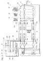
- a power supply device 10 includes multiple, that is, m power supply units 11, ... , 11 that are connected in parallel (m is a natural number of 2 or more) as shown in, for example, FIG. 1 .
- the power supply device 10 includes a positive electrode-side junction P that is formed by the joining of positive electrode-side terminals 11p of the m power supply units 11, ... , 11; and a negative electrode-side junction N that is formed by the joining of negative electrode-side terminals 11n of the power supply units 11.
- the positive electrode-side junction P and the negative electrode-side junction N of the power supply device 10 form a positive electrode-side output terminal and a negative electrode-side output terminal that are connected to external appropriate power apparatus E.
- m power supply units 11, ... , 11 are connected in parallel to the positive electrode-side output terminal and the negative electrode-side output terminal.
- the external appropriate power apparatus E includes, for example, a smoothing capacitor C and an electric load L that are connected in parallel between the positive electrode-side output terminal and the negative electrode-side output terminal.
- Each of the power supply units 11 includes, for example, a battery unit 21 that is formed of a plurality of battery cells 21 a, ... , 21 a connected in series; a positive electrode-side contactor 22 that is electrically disconnectably connected in series between a positive electrode terminal 21p of the battery unit 21 and the positive electrode-side junction P; a negative electrode-side contactor 23 that is electrically disconnectably connected in series between a negative electrode terminal 21n of the battery unit 21 and the negative electrode-side junction N; and a current sensor 24 that is connected in series between the negative electrode-side contactor 23 and the negative electrode-side junction N.
- the battery unit 21 includes, for example, a manual cut-off mechanism 25 that is provided at an appropriate connection position between the plurality of battery cells 21a, ... , 21a connected in series and is formed of a switch or the like capable of being connected and disconnected by the operation of an operator.
- the power supply device 10 includes a precharge unit 30 between the positive electrode-side junction P and the positive electrode terminals 21p of the power supply units 11.
- the precharge unit 30 includes precharge resistors 31 each of which one end 31a is connected between each positive electrode-side contactor 22 and the positive electrode terminal 21 p of the battery unit 21 of each power supply unit 11, and one precharge contactor 32.
- the other end 31b of at least one precharge resistor 31 (31A) among m precharge resistors 31, ... , 31 of m power supply units 11, ... , 11 is connected to one end 31a of the other precharge resistors 31 (31B).
- the precharge contactor 32 can cut off current that flows to the positive electrode-side junction P from the power supply units 11 through the other precharge resistors 31 (31B), and can allow the flow of the current.
- the precharge contactor 32 is connected in series between the other end 31b of the other precharge resistor 31 (31B) and the positive electrode-side junction P or between the other precharge resistor 31 (31B) and the other end 31b of at least one precharge resistor 31 (31A).
- the precharge contactor 32 is connected in series between the other ends 31b of the other precharge resistors 31 (31B) and the positive electrode-side junction P.
- the other ends 31b, ... , 31b of m-1 precharge resistors 31 (31A), ... , 31 (31A) among m precharge resistors 31, ... , 31 are connected to one end 31a of one other precharge resistor 31 (31B).
- the one precharge contactor 32 is connected in series between one other precharge resistor 31 (31B) and the other ends 31b, ... , 31b of m-1 precharge resistors 31 (31A), ... , 31 (31A) or between the other end 31b of one other precharge resistor 31 (31B) and the positive electrode-side junction P.
- m-1 precharge resistors 31 (31A), ... , 31 (31A) among m precharge resistors 31, ... , 31 are connected in series so that the one ends 31a and the other ends 31b of the precharge resistors are connected to each other.
- the other end 31b of this series connection is connected to one end 31a of one other precharge resistor 31 (31B).
- one precharge contactor 32 is connected in series between one other precharge resistor 31 (31B) and the other end 31b of the series connection of m-1 precharge resistors 31 (31A), ... , 31 (31A), or between the other end 31b of one other precharge resistor 31 (31B) and the positive electrode-side junction P.
- m-2 precharge resistors 31 (31A), ... , 31 (31A) among m precharge resistors 31, ... , 31 are connected in series so that the one ends 31a and the other ends 31b the precharge resistors are connected to each other.
- the other end 31b of this series connection is connected to one end 31a of one of two other precharge resistors 31 (31B) and 31 (31B).
- the one precharge contactor 32 is connected in series between the other ends 31b and 31b of two other precharge resistors 31 (31B) and 31 (31B) and the positive electrode-side junction P.
- the other ends 31b, ... , 31b of m-2 precharge resistors 31 (31A), ... , 31 (31A) among m precharge resistors 31, ... , 31 are connected to one end 31a of one other precharge resistor 31 (31A) and the other end 31b of the one other precharge resistor 31 (31A) is connected to one end 31a of one other precharge resistor 31 (31B).
- one precharge contactor 32 is connected in series between one other precharge resistor 31 (31B) and the other end 31b of the series connection of m-2 precharge resistors 31 (31A), ... , 31 (31A) and one precharge resistor 31 (31A), or between the other end 31b of one other precharge resistor 31 (31B) and the positive electrode-side junction P.
- a precharge unit 30 shown in FIG. 4B two precharge resistors 31 (31A) and 31 (31A) among m precharge resistors 31,..., 31 are connected in series so that one end 31a and the other end 31b of the precharge resistors are connected to each other. Furthermore, the other end 31b of this series connection and the other ends 31b, ... , 31b of m-3 precharge resistors 31 (31A), ... , 31 (31A) are connected to one end 31a of one other precharge resistor 31 (31B).
- one precharge contactor 32 is connected in series between one other precharge resistor 31 (31B) and the other end 31b of the series connection of two precharge resistors 31 (31A) and 31 (31A) and the other ends 31b, ... , 31b of m-3 precharge resistors 31 (31A), ... , 31 (31A), or between the other end 31b of one other precharge resistor 31 (31B) and the positive electrode-side junction P.
- each of a plurality of precharge resistors 31 (31A), ... , 31 (31A) and each of a plurality of other precharge resistor 31 (31B), ... , 31 (31B) are connected in series, so that a plurality of series connections are formed.
- one precharge contactor 32 is connected in series between the other ends 31b of the other precharge resistors 31 (31B) of the plurality of series connections and the positive electrode-side junction P.
- a precharge unit 30 shown in FIG. 5B among m precharge resistors 31, ... , 31, the other ends 31b, ... , 31b of m-2 precharge resistors 31 (31A), ... , 31 (31A) are connected to one end 31a of one of two other precharge resistors 31 (31B) and 31 (31B).
- the one precharge contactor 32 is connected in series between the other ends 31b and 31b of the two other precharge resistors 31 (31B) and 31 (31B) and the positive electrode-side junction P.
- a precharge unit 30 shown in FIG. 5C among m precharge resistors 31,..., 31, one precharge resistor 31 (31A) and one other precharge resistor 31 (31B) are connected in series to each other and the other end 31b of this series connection and the other ends 31b, ... , 31b of m-2 precharge resistor 31 (31B), ... , 31 (31B) are connected to one precharge contactor 32.
- the one precharge contactor 32 is connected in series between the positive electrode-side junction P and the other end 31b of the series connection of one precharge resistor 31 (31A) and one other precharge resistor 31 (31B) and the other ends 31b, ... , 31b of m-2 other precharge resistor 31 (31B), ... , 31 (31B).
- the number (m) of the plurality of battery units 21, ... , 21, the number (m) of the plurality of positive electrode-side contactors 22, ... , 22, the number (m) of the plurality of negative electrode-side contactors 23, ... , 23, the number (m) of a plurality of current sensors 24, ... , 24, and the number (m) of the plurality of precharge resistors 31,..., 31 are equal to each other; and the number (one) of the precharge contactor 32 is set to a numeral smaller than the number (m) of these.
- the power supply device 10 has the above-mentioned configuration, and the operation of the power supply device 10 will be described next.
- the positive electrode-side contactors 22 are set to a disconnection state and the respective negative electrode-side contactors 23 and the precharge contactor 32 are set to a connection state.
- the precharge contactor 32 is set to a disconnection state and the respective positive electrode-side contactors 22 and the respective negative electrode-side contactors 23 are set to a connection state.
- one precharge contactor 32 is provided so as to cut off current, which flows to the positive electrode-side junction P through the precharge resistors 31 for the plurality of power supply units 11,... , 11, and allow the flow of the current.
- the power supply device 10 charges the smoothing capacitor C of the power supply device 10 through the precharge resistors 31 before the positive electrode-side contactors 22 are set to a connection state and has a precharge function of suppressing excessive inrush current when the positive electrode-side contactors 22 are set to a connection state.
- the number (one) of the precharge contactor 32 is smaller than the number of the power supply units 11, ... , 11. Accordingly, as compared to, for example, the case where each of the power supply units 11, ... , 11 is provided with the precharge contactor 32, it is possible to suppress the increase of the costs required to form the power supply device and to suppress the deterioration of the mountability of the power supply device that is caused by the increase in the size of the power supply device.
- the power supply device includes the negative electrode-side contactors 23 that are electrically disconnectably connected in series between the negative electrode terminals 21n of the battery units 21 and the negative electrode-side junction N, in addition to the respective positive electrode-side contactors 22. Accordingly, even though abnormality occurs in, for example, the positive electrode-side contactors 22, it is possible to appropriately disconnect the battery units 21 from the external power apparatus E by the negative electrode-side contactors 23.
- the power supply device has included one precharge contactor 32 in the above-mentioned embodiment.
- the invention is not limited thereto, and the power supply device may include a plurality of precharge contactors 32, ... , 32 of which the number (two or more and equal to or smaller than m-1) is smaller than the number of the plurality of (m) power supply units 11, ... , 11.
- the precharge unit 30 has been provided on the side close to the positive electrodes of the battery units 21 in the above-mentioned embodiment.
- the invention is not limited thereto, and the precharge unit 30 may be provided on the side close to the negative electrodes of the battery units 21 as in, for example, a power supply device 10 according to a first modification of the above-mentioned embodiment shown in FIG. 6 .
- the power supply device 10 includes the precharge unit 30 between the negative electrode terminals 21n of the power supply units 11 and the negative electrode-side junction N.
- the precharge unit 30 includes precharge resistors 31 each of which one end 31a is connected between each negative electrode-side contactor 23 and the negative electrode terminal 21n of the battery unit 21 of each power supply unit 11, and one precharge contactor 32.
- the other end 31b of at least one precharge resistor 31 (31A) among m precharge resistors 31, ... , 31 of m power supply units 11,..., 11 is connected to one end 31a of the other precharge resistor 31 (31B).
- the precharge contactor 32 can cut off current that flows to the negative electrode-side junction N from the power supply units 11 through the other precharge resistor 31 (31B), and can allow the flow of the current.
- the precharge contactor 32 is connected in series between the other end 31b of the other precharge resistor 31 (31B) and the negative electrode-side junction N or between the other precharge resistor 31 (31B) and the other end 31b of at least one precharge resistor 31 (31A).
- the precharge contactor 32 is connected in series between the other ends 31b of the other precharge resistors 31 (31B) and the negative electrode-side junction N.
- m-1 balancing resistors 41,..., 41, which connect the battery units 21, may be provided between the negative electrode terminals 21n of m battery units 21,... 21 and m negative electrode-side contactors 23,..., 23 on the side close to the electrode terminals, to which the precharge resistors 31 are not connected, of the positive electrode terminals 21p and the negative electrode terminals 21n of the battery units 21, for example, the negative electrode terminals 21n shown in FIG. 7 .
- the number (m-1) of the balancing resistors 41, ... , 41 is smaller than the number (m) of the battery units 21,..., 21 by one as shown in, for example, FIGS. 8 to 11 . Accordingly, the number of the battery units 21, which are connected to only one balancing resistor 41, is two or more.
- the battery units 21,..., 21, of which the number is larger than 1 and smaller than m are connected to one other battery unit 21.
- each of all the battery units 21, ... , 21 cannot be connected to only one other battery unit 21 by one balancing resistor 41.
- the number of battery units 21, which are connected to only one other battery unit 21 by one balancing resistor 41, among m battery units 21, ..., 21 is smaller than m.
- each of two battery units 21 and 21 is connected to two other battery units 21 and 21 by two balancing resistors 41 and 41 and each of two battery units 21 and 21 is connected to one other battery unit 21 by one balancing resistor 41.
- one battery unit 21 is connected to three other battery units 21, 21, and 21 by three balancing resistors 41, 41, and 41 and each of the three battery units 21, 21, and 21 is connected to one other battery unit 21 by one balancing resistor 41.
- one battery unit 21 is connected to three other battery units 21, 21, and 21 by three balancing resistors 41, 41, and 41, one battery unit 21 is connected to two other battery units 21 and 21 by two balancing resistors 41 and 41, and each of three battery units 21, 21, and 21 is connected to one other battery unit 21 by one balancing resistor 41.
- one battery unit 21 is connected to four other battery units 21, ... , 21 by four balancing resistors 41, ... , 41 and each of four battery units 21,... , 21 is connected to one other battery unit 21 by one balancing resistor 41.
- each of four battery units 21, ... , 21 is connected to two other battery units 21 and 21 by two balancing resistors 41 and 41 and each of two battery units 21 and 21 is connected to one other battery unit 21 by one balancing resistor 41.
- one battery unit 21 is connected to three other battery units 21,21, and 21 by three balancing resistors 41, 41, and 41, each of two battery units 21 and 21 is connected to two other battery units 21 and 21 by two balancing resistors 41 and 41, and each of three battery units 21, 21, and 21 is connected to one other battery unit 21 by one balancing resistor 41.
- each of two battery units 21 and 21 is connected to three other battery units 21, 21, and 21 by three balancing resistors 41, 41, and 41 and each of four battery units 21, ... , 21 is connected to one other battery unit 21 by one balancing resistor 41.
- one battery unit 21 is connected to four other battery units 21, ... , 21 by four balancing resistors 41, ... , 41, one battery unit 21 is connected to two other battery units 21 and 21 1 by two balancing resistors 41 and 41, and each of four battery units 21, ... , 21 is connected to one other battery unit 21 by one balancing resistor 41.
- one battery unit 21 is connected to four other battery units 21, ... , 21 by four balancing resistors 41, ... , 41 and each of four battery units 21, ... , 21 is connected to one other battery unit 21 by one balancing resistor 41.
- closed-loop circuits where m battery units 21, ... , 21 are connected to each other by m-1 balancing resistors 41, ... , 41 and m-1 precharge resistors 31 (31A), ... , 31 (31A) are formed regardless of the connection/disconnection states of m negative electrode-side contactors 23, ... , 23. Accordingly, it is possible to appropriately eliminate the variation of voltage (the variation of capacity) between the plurality of battery units 21, ... , 21.
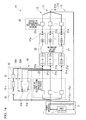
- m balancing resistors 41, ... , 41, which connect the battery units 21, may be provided on the side close to the electrode terminals, to which the precharge resistors 31 are not connected, of the positive electrode terminals 21p and the negative electrode terminals 21n of the battery units 21, for example, the negative electrode terminals 21n shown in FIG. 12 .
- the power supply device 10 shown in FIG. 12 includes m balancing resistors 41, ... , 41 that connect the battery units 21 and are provided between the negative electrode terminals 21n of m battery units 21, ... , 21 and m negative electrode-side contactors 23, ... , 23.
- the plurality of current sensors 24, ... , 24 may be disposed on the outside of closed-loop circuits where m battery units 21, ... , 21 are connected to each other by a plurality of (m or m-1) balancing resistors 41, ... , 41 and m-1 precharge resistors 31, ... , 31.
- a current sensor 24 may be connected between the balancing resistor 41 and the negative electrode-side contactor 23 in each of the power supply units 11.
- a plurality of current sensors 24, ... , 24 are disposed on the outside of closed-loop circuits where m battery units 21, ... , 21 are connected to each other by a plurality of (m or m-1) balancing resistors 41, ... , 41 and m-1 precharge resistors 31 (31A), ... , 31 (31A). Therefore, it is possible to appropriately calibrate the current sensors 24.
- relays which can disconnect the battery units 21 from an external power apparatus E, that is, negative electrode-side contactors 23 may be omitted from the side close to the electrode terminals, to which the precharge resistors 31 are not connected, of the positive electrode terminals 21p and the negative electrode terminals 21n of the respective battery units 21, for example, the negative electrode terminals 21n shown in FIG. 15 .
- a power supply device includes a plurality of power supply units connected in parallel, and includes a positive electrode-side junction formed by the joining of positive electrode-side terminals of the plurality of power supply units and a negative electrode-side junction formed by the joining of negative electrode-side terminals of the plurality of power supply units.
- Each of the plurality of power supply units includes a battery unit, and a first relay that is provided between one of the positive and negative electrode-side junctions and the battery unit and is electrically disconnectably connected in series to the battery unit.
- Each of the plurality of power supply units includes a resistive element of which one end is connected between the first relay, which is connected to one of a positive electrode terminal and a negative electrode terminal of the battery unit, and the battery unit.
Landscapes
- Engineering & Computer Science (AREA)
- Chemical & Material Sciences (AREA)
- Chemical Kinetics & Catalysis (AREA)
- Electrochemistry (AREA)
- General Chemical & Material Sciences (AREA)
- Manufacturing & Machinery (AREA)
- Power Engineering (AREA)
- Microelectronics & Electronic Packaging (AREA)
- Charge And Discharge Circuits For Batteries Or The Like (AREA)
- Secondary Cells (AREA)
Abstract
Description
- The present invention relates to a power supply device.
- All patents, patent applications, patent publications, scientific articles, and the like, which will hereinafter be cited or identified in the present application, will hereby be incorporated by reference in their entirety in order to describe more fully the state of the art to which the present invention pertains.
- For example, a power supply device that includes a plurality of batteries connected in parallel has been known. In the power supply device, positive-side main relays are connected in series between an electric load connected to the power supply device and positive electrode-side terminals of the respective batteries, negative-side main relays are connected in series between the electric load and negative electrode-side terminals of the respective batteries, and precharge circuits where resistors and relays for precharge are connected in series are connected in parallel with the positive-side main relays (for example, see Japanese Unexamined Patent Application, First Publication No.
2008-35581 - In the power supply device, the positive-side main relays are opened and the relays of the precharge circuits are connected for the purpose of preventing excessive current flowing to the electric load. Accordingly, current flows through the resistors of the precharge circuits.
- Further, for example, an electric storage device that includes a plurality of batteries connected in parallel has been known. In the electric storage device, resistive elements for eliminating the variation of voltage between the plurality of batteries are connected in series between an electric load connected to the electric storage device and positive electrode-side terminals of the batteries, and resistor short-circuit switches are connected in parallel with the resistive elements (for example, see Japanese Unexamined Patent Application, First Publication No.
2009-212020 - In the electric storage device, the resistor short-circuit switches are turned off and the plurality of batteries are connected to each other by the resistive elements for the purpose of eliminating the variation of voltage between the plurality of batteries. Accordingly, current flows through the resistive elements between the plurality of batteries.
- Meanwhile, according to the power supply device in the related art, as the number of the batteries connected in parallel is increased, the number of the precharge circuits is also increased. For this reason, the costs required to form the power supply device are increased and the mountability of the power supply device deteriorates due to the increase in the size of the power supply device.
- For example, when relays are connected between junctions of the plurality of batteries and a load, it is possible to reduce the number of required relays. However, the current capacities of the relays need to be increased and the costs required to form the power supply device are increased.
- Further, if the resistive elements are provided only in order to eliminate the variation of voltage between the plurality of batteries as in the electric storage device in the related art, the costs required to form the device are increased.
- The invention provides a power supply device capable of appropriately preventing the output of excessive current and appropriately eliminating the variation of voltage between a plurality of batteries while suppressing the increase in the costs required to form a device and the increase in the size of a device.
- The first aspect of the invention is a power supply device that includes a plurality of power supply units connected in parallel, and includes a positive electrode-side junction formed by the joining of positive electrode-side terminals of the plurality of power supply units and a negative electrode-side junction formed by the joining of negative electrode-side terminals of the plurality of power supply units, wherein each of the plurality of power supply units includes a battery unit, and a first relay that is provided between one of the positive and negative electrode-side junctions and the battery unit and is electrically disconnectably connected in series to the battery unit, each of the plurality of power supply units includes a resistive element of which one end is connected between the first relay, which is connected to one of a positive electrode terminal and a negative electrode terminal of the battery unit, and the battery unit, and the other end of at least one resistive element of the resistive elements of the plurality of power supply units is connected to one ends of the other resistive elements that are other than the at least one resistive element, the power supply device comprising: second relays that cut off current flowing to one of the positive and negative electrode-side junctions connected to the first relays of the plurality of power supply units from the plurality of power supply units through the other resistive elements and allow the flow of the current.
- The second aspect of the invention is the power supply device according to the first aspect of the invention, wherein if the number of the other resistive elements is one, the second relays are connected between the other end of the other resistive element and any one, which is connected to the first relays, of the positive and negative electrode-side junctions or between the other resistive element and the other end of the at least one resistive element.
- The third aspect of the invention is the power supply device according to the first aspect of the invention, wherein if the number of the other resistive elements is two or more, the second relays are connected between the other ends of the other resistive elements and any one, which is connected to the first relays, of the positive and negative electrode-side junctions.
- The fourth aspect of the invention is the power supply device according to any one of the first, second and third aspects of the invention, further comprising: third relays that are electrically disconnectably connected between the other of the positive and negative electrode-side junctions and the battery units.
- The fifth aspect of the invention is the power supply device according to the fourth aspect of the invention, further comprising: balancing resistive elements that are provided between the battery units of the plurality of power supply units and the third relays and connect the battery units, wherein the third relays are connected in series to the battery units of the plurality of power supply units and the number of the third relays is equal to the number of the plurality of power supply units.
- The sixth aspect of the invention is the power supply device according to the fifth aspect of the invention, wherein the number of the balancing resistive elements is set to m-1 when the number of the battery units is an arbitrary natural number m of 2 or more, and among the m battery units, the battery units of which the number is larger than 1 and smaller than m are connected to the other one battery unit.
- The seventh aspect of the invention is the power supply device according to the fifth aspect of the invention, wherein the number of the balancing resistive elements is set to m when the number of the battery units is an arbitrary natural number m of 2 or more, and among the m battery units, all the battery units are connected to the other two battery units.
- The eighth aspect of the invention is the power supply device according to any one of the fifth, sixth and seventh aspect of the invention, wherein the battery units of the plurality of power supply units include current sensors on the outside of closed-loop circuits that includes the battery units, the resistive elements, and the balancing resistive elements.
- The power supply device according to the first aspect of the invention charges a smoothing capacitor of the power supply device through the resistive elements before the first relays are set to a connection state and has a precharge function of suppressing excessive inrush current when the first relays are set to a connection state.
- Moreover, the second relays can cut off current flowing to the plurality of power supply units, which are connected in parallel, through the other resistive elements having one end to which the other end of at least one resistive element, and can allow the flow of the current.
- Accordingly, the number of the second relays is smaller than the number of the plurality of power supply units. As compared to, for example, a case where each of the power supply units is provided with the second relays, it is possible to suppress the increase in the costs required to form the power supply device and to suppress the deterioration of the mountability of the power supply device that is caused by the increase in the size of the power supply device.
- Further, closed circuits where the plurality of battery units are connected to each other by the resistive elements are formed. Accordingly, it is possible to appropriately eliminate the variation of voltage (the variation of capacity) between the plurality of battery units without requiring, for example, special circuit elements.
- Furthermore, according to the power supply device of the second aspect of the invention, if the number of the other resistive elements is one, it is possible to cut off current flowing to one of the positive and negative electrode-side junctions and to allow the flow of the current by the second relays that are connected to one end or the other end of the other resistive element.
- Moreover, according to the power supply device of the third aspect of the invention, if the number of the other resistive elements is two or more, it is possible to cut off current flowing to one of the positive and negative electrode-side junctions and to allow the flow of the current by the second relays that are connected to the other ends of the other resistive elements.
- In addition, the power supply device according to the fourth aspect of the invention includes third relays that are electrically disconnectably connected between the battery units and the other of the positive and negative electrode-side junctions, that is, the junction, where the first relays are not connected between the battery units, and the battery units, in addition to the first relays.
- Accordingly, even though abnormality occurs in, for example, the first relays, it is possible to appropriately disconnect the battery units from an external electric load by way of the third relays.
- Further, the power supply device according to the fifth aspect of the invention includes balancing resistive elements that are provided between the battery units of the plurality of power supply units and the third relays and connect the plurality of battery units.
- Accordingly, closed-loop circuits where the plurality of battery units are connected to each other by the balancing resistors and the resistive elements are formed regardless of the connection/disconnection states of the third relays. Accordingly, it is possible to appropriately eliminate the variation of voltage (the variation of capacity) between the plurality of battery units.
- Furthermore, according to the power supply device of the sixth aspect of the invention, it is possible to appropriately eliminate the variation of voltage (the variation of capacity) between the plurality of battery units while preventing the number of required balancing resistive elements from being excessively increased.
- Moreover, according to the power supply device of the seventh aspect of the invention, it is possible to connect m balancing resistive elements to m battery units by delta connection. Accordingly, even though abnormality occurs in one balancing resistive element, it is possible to appropriately maintain closed-loop circuits and to appropriately eliminate the variation of voltage (the variation of capacity) between the plurality of battery units.
- In addition, according to the power supply device of the eighth aspect of the invention, current sensors are provided on the outside of closed-loop circuits. Therefore, it is possible to appropriately calibrate the current sensors.
- The above features and advantages of the present invention will be more apparent from the following description of certain preferred embodiments taken in conjunction with the accompanying drawings, in which:
-
FIG. 1 is a view showing the configuration of a power supply device according to an embodiment of the invention. -
FIG. 2 is a view showing an example of the configuration of a precharge unit of the power supply device according to the embodiment of the invention. -
FIG. 3 is a view showing an example of the configuration of the precharge unit of the power supply device according to the embodiment of the invention. -
FIGS. 4A and 4B are views showing an example of the configuration of the precharge unit of the power supply device according to the embodiment of the invention. -
FIGS. 5A, 5B and 5C are views showing an example of the configuration of the precharge unit of the power supply device according to the embodiment of the invention. -
FIG. 6 is a view showing an example of the configuration of a power supply device according to a first modification of the embodiment of the invention. -
FIG. 7 is a view showing an example of the configuration of a power supply device according to a second modification of the embodiment of the invention. -
FIG. 8 is a view showing an example of the connection between m battery units and m-1 balancing resistors when m of the power supply device according to the second modification of the embodiment of the invention is 3. -
FIGS. 9A and 9B are views showing an example of the connection between m battery units and m-1 balancing resistors when m of the power supply device according to the second modification of the embodiment of the invention is 4. -
FIGS. 10A, 10B and 10C are views showing an example of the connection between m battery units and m-1 balancing resistors when m of the power supply device according to the second modification of the embodiment of the invention is 5. -
FIGS. 11A, 11B, 11C, 11D and 11E are views showing an example of the connection between m battery units and m-1 balancing resistors when m of the power supply device according to the second modification of the embodiment of the invention is 6. -
FIG. 12 is a view showing the configuration of a power supply device according to a third modification of the embodiment of the invention. -
FIG. 13 is a view showing the configuration of a power supply device according to a fourth modification of the embodiment of the invention. -
FIG. 14 is a view showing the configuration of a power supply device according to a fifth modification of the embodiment of the invention. -
FIG. 15 is a view showing the configuration of a power supply device according to a sixth modification of the embodiment of the invention. - The present invention will be now described herein with reference to illustrative preferred embodiments. Those skilled in the art will recognize that many alternative preferred embodiments can be accomplished using the teaching of the present invention and that the present invention is not limited to the preferred embodiments illustrated for explanatory purpose.
- A
power supply device 10 according to this embodiment includes multiple, that is, mpower supply units 11, ... , 11 that are connected in parallel (m is a natural number of 2 or more) as shown in, for example,FIG. 1 . Thepower supply device 10 includes a positive electrode-side junction P that is formed by the joining of positive electrode-side terminals 11p of the mpower supply units 11, ... , 11; and a negative electrode-side junction N that is formed by the joining of negative electrode-side terminals 11n of thepower supply units 11. - That is, the positive electrode-side junction P and the negative electrode-side junction N of the
power supply device 10 form a positive electrode-side output terminal and a negative electrode-side output terminal that are connected to external appropriate power apparatus E. mpower supply units 11, ... , 11 are connected in parallel to the positive electrode-side output terminal and the negative electrode-side output terminal. - Meanwhile, the external appropriate power apparatus E includes, for example, a smoothing capacitor C and an electric load L that are connected in parallel between the positive electrode-side output terminal and the negative electrode-side output terminal.
- Each of the
power supply units 11 includes, for example, abattery unit 21 that is formed of a plurality ofbattery cells 21 a, ... , 21 a connected in series; a positive electrode-side contactor 22 that is electrically disconnectably connected in series between apositive electrode terminal 21p of thebattery unit 21 and the positive electrode-side junction P; a negative electrode-side contactor 23 that is electrically disconnectably connected in series between anegative electrode terminal 21n of thebattery unit 21 and the negative electrode-side junction N; and acurrent sensor 24 that is connected in series between the negative electrode-side contactor 23 and the negative electrode-side junction N. - Meanwhile, the
battery unit 21 includes, for example, a manual cut-off mechanism 25 that is provided at an appropriate connection position between the plurality ofbattery cells 21a, ... , 21a connected in series and is formed of a switch or the like capable of being connected and disconnected by the operation of an operator. - Further, the
power supply device 10 includes aprecharge unit 30 between the positive electrode-side junction P and thepositive electrode terminals 21p of thepower supply units 11. - The
precharge unit 30 includesprecharge resistors 31 each of which oneend 31a is connected between each positive electrode-side contactor 22 and thepositive electrode terminal 21 p of thebattery unit 21 of eachpower supply unit 11, and oneprecharge contactor 32. - The
other end 31b of at least one precharge resistor 31 (31A) among m precharge resistors 31, ... , 31 of mpower supply units 11, ... , 11 is connected to oneend 31a of the other precharge resistors 31 (31B). - Moreover, the
precharge contactor 32 can cut off current that flows to the positive electrode-side junction P from thepower supply units 11 through the other precharge resistors 31 (31B), and can allow the flow of the current. - If the number of the other precharge resistors 31 (31B) is one, the
precharge contactor 32 is connected in series between theother end 31b of the other precharge resistor 31 (31B) and the positive electrode-side junction P or between the other precharge resistor 31 (31B) and theother end 31b of at least one precharge resistor 31 (31A). - Further, if the number of the other precharge resistors 31 (31B) is two or more, the
precharge contactor 32 is connected in series between the other ends 31b of the other precharge resistors 31 (31B) and the positive electrode-side junction P. - For example, in the
power supply device 10 shown inFIG. 1 , the other ends 31b, ... , 31b of m-1 precharge resistors 31 (31A), ... , 31 (31A) among m precharge resistors 31, ... , 31 are connected to oneend 31a of one other precharge resistor 31 (31B). - Further, the one
precharge contactor 32 is connected in series between one other precharge resistor 31 (31B) and the other ends 31b, ... , 31b of m-1 precharge resistors 31 (31A), ... , 31 (31A) or between theother end 31b of one other precharge resistor 31 (31B) and the positive electrode-side junction P. - Furthermore, for example, in a
power supply device 10 shown inFIG. 2 , m-1 precharge resistors 31 (31A), ... , 31 (31A) among m precharge resistors 31, ... , 31 are connected in series so that the one ends 31a and the other ends 31b of the precharge resistors are connected to each other. In addition, theother end 31b of this series connection is connected to oneend 31a of one other precharge resistor 31 (31B). - Further, one
precharge contactor 32 is connected in series between one other precharge resistor 31 (31B) and theother end 31b of the series connection of m-1 precharge resistors 31 (31A), ... , 31 (31A), or between theother end 31b of one other precharge resistor 31 (31B) and the positive electrode-side junction P. - Furthermore, for example, in a
power supply device 10 shown inFIG. 3 , m-2 precharge resistors 31 (31A), ... , 31 (31A) among m precharge resistors 31, ... , 31 are connected in series so that the one ends 31a and the other ends 31b the precharge resistors are connected to each other. In addition, theother end 31b of this series connection is connected to oneend 31a of one of two other precharge resistors 31 (31B) and 31 (31B). - Further, the other ends 3 1 b and 31b of two other precharge resistors 31 (31B) and 31 (31B) are connected to one
precharge contactor 32. - The one
precharge contactor 32 is connected in series between the other ends 31b and 31b of two other precharge resistors 31 (31B) and 31 (31B) and the positive electrode-side junction P. - Furthermore, for example, in a
precharge unit 30 shown inFIG. 4A , the other ends 31b, ... , 31b of m-2 precharge resistors 31 (31A), ... , 31 (31A) among m precharge resistors 31, ... , 31 are connected to oneend 31a of one other precharge resistor 31 (31A) and theother end 31b of the one other precharge resistor 31 (31A) is connected to oneend 31a of one other precharge resistor 31 (31B). - Moreover, one
precharge contactor 32 is connected in series between one other precharge resistor 31 (31B) and theother end 31b of the series connection of m-2 precharge resistors 31 (31A), ... , 31 (31A) and one precharge resistor 31 (31A), or between theother end 31b of one other precharge resistor 31 (31B) and the positive electrode-side junction P. - Further, for example, in a
precharge unit 30 shown inFIG. 4B , two precharge resistors 31 (31A) and 31 (31A) among m precharge resistors 31,..., 31 are connected in series so that oneend 31a and theother end 31b of the precharge resistors are connected to each other. Furthermore, theother end 31b of this series connection and the other ends 31b, ... , 31b of m-3 precharge resistors 31 (31A), ... , 31 (31A) are connected to oneend 31a of one other precharge resistor 31 (31B). - Moreover, one
precharge contactor 32 is connected in series between one other precharge resistor 31 (31B) and theother end 31b of the series connection of two precharge resistors 31 (31A) and 31 (31A) and the other ends 31b, ... , 31b of m-3 precharge resistors 31 (31A), ... , 31 (31A), or between theother end 31b of one other precharge resistor 31 (31B) and the positive electrode-side junction P. - Further, for example, in a
precharge unit 30 shown inFIG. 5A , among m precharge resistors 31, ... , 31, each of a plurality of precharge resistors 31 (31A), ... , 31 (31A) and each of a plurality of other precharge resistor 31 (31B), ... , 31 (31B) are connected in series, so that a plurality of series connections are formed. - Furthermore, one
precharge contactor 32 is connected in series between the other ends 31b of the other precharge resistors 31 (31B) of the plurality of series connections and the positive electrode-side junction P. - Moreover, for example, in a
precharge unit 30 shown inFIG. 5B , among m precharge resistors 31, ... , 31, the other ends 31b, ... , 31b of m-2 precharge resistors 31 (31A), ... , 31 (31A) are connected to oneend 31a of one of two other precharge resistors 31 (31B) and 31 (31B). - Further, the other ends 31b and 31b of the two other precharge resistors 31 (31B) and 31 (31B) are connected to one
precharge contactor 32. - The one
precharge contactor 32 is connected in series between the other ends 31b and 31b of the two other precharge resistors 31 (31B) and 31 (31B) and the positive electrode-side junction P. - Furthermore, for example, a
precharge unit 30 shown inFIG. 5C , among m precharge resistors 31,..., 31, one precharge resistor 31 (31A) and one other precharge resistor 31 (31B) are connected in series to each other and theother end 31b of this series connection and the other ends 31b, ... , 31b of m-2 precharge resistor 31 (31B), ... , 31 (31B) are connected to oneprecharge contactor 32. - The one
precharge contactor 32 is connected in series between the positive electrode-side junction P and theother end 31b of the series connection of one precharge resistor 31 (31A) and one other precharge resistor 31 (31B) and the other ends 31b, ... , 31b of m-2 other precharge resistor 31 (31B), ... , 31 (31B). - Meanwhile, in the
power supply device 10, the number (m) of the plurality ofbattery units 21, ... , 21, the number (m) of the plurality of positive electrode-side contactors 22, ... , 22, the number (m) of the plurality of negative electrode-side contactors 23, ... , 23, the number (m) of a plurality ofcurrent sensors 24, ... , 24, and the number (m) of the plurality ofprecharge resistors 31,..., 31 are equal to each other; and the number (one) of theprecharge contactor 32 is set to a numeral smaller than the number (m) of these. - The
power supply device 10 according to this embodiment has the above-mentioned configuration, and the operation of thepower supply device 10 will be described next. - For example, when a difference between the voltage of the
power supply device 10 and the voltage of the smoothing capacitor C is greater than or equal to a predetermined value such as when power begins to be supplied to an external electric load L from thepower supply device 10, first, current is made to flow through the respectiveprecharge resistors 31 so that the smoothing capacitor C is gradually charged. Accordingly, the positive electrode-side contactors 22 are set to a disconnection state and the respective negative electrode-side contactors 23 and theprecharge contactor 32 are set to a connection state. - Therefore, it is possible to suppress the flow of excessive inrush current, and to prevent the generation of a problem such as the welding of electrical contacts that are provided at, for example, the
contactors - Further, after the difference between the voltage of the
power supply device 10 and the voltage of the smoothing capacitor C becomes smaller than the predetermined value, current is made to flow through the respective positive electrode-side contactors 22. Accordingly, theprecharge contactor 32 is set to a disconnection state and the respective positive electrode-side contactors 22 and the respective negative electrode-side contactors 23 are set to a connection state. - In this state, closed circuits where
m battery units 21,..., 21 are connected to each other by m-1precharge resistors 31,..., 31 are formed between the other ends 31b,..., 31b of m-1 precharge resistors 31 (31A),.... 31 (31A) and the negative electrode-side junction N. Accordingly, the variation of voltage (the variation of capacity) between mbattery units 21,..., 21 is eliminated, so that voltage and capacity are equalized. - As described above, according to the
power supply device 10 of this embodiment, oneprecharge contactor 32 is provided so as to cut off current, which flows to the positive electrode-side junction P through theprecharge resistors 31 for the plurality ofpower supply units 11,... , 11, and allow the flow of the current. - Accordingly, when the
precharge contactor 32 is in a connection state, current flows through theprecharge resistors 31. Therefore, it is possible to appropriately prevent excessive current from flowing through an external power apparatus E that is connected to thepower supply device 10. - That is, the
power supply device 10 charges the smoothing capacitor C of thepower supply device 10 through theprecharge resistors 31 before the positive electrode-side contactors 22 are set to a connection state and has a precharge function of suppressing excessive inrush current when the positive electrode-side contactors 22 are set to a connection state. - Moreover, as for m
power supply units 11,..., 11 connected in parallel, the number (one) of theprecharge contactor 32 is smaller than the number of thepower supply units 11, ... , 11. Accordingly, as compared to, for example, the case where each of thepower supply units 11, ... , 11 is provided with theprecharge contactor 32, it is possible to suppress the increase of the costs required to form the power supply device and to suppress the deterioration of the mountability of the power supply device that is caused by the increase in the size of the power supply device. - Further, closed circuits where
m battery units 21,..., 21 are connected to each other by m-1 precharge resistors 31 (31A),..., 31 (31A) are formed. Accordingly, it is possible to appropriately eliminate the variation of voltage (the variation of capacity) between the plurality ofbattery units 21,.... 21 without requiring, for example, special circuit elements. - Furthermore, the power supply device includes the negative electrode-
side contactors 23 that are electrically disconnectably connected in series between thenegative electrode terminals 21n of thebattery units 21 and the negative electrode-side junction N, in addition to the respective positive electrode-side contactors 22. Accordingly, even though abnormality occurs in, for example, the positive electrode-side contactors 22, it is possible to appropriately disconnect thebattery units 21 from the external power apparatus E by the negative electrode-side contactors 23. - Meanwhile, the power supply device has included one
precharge contactor 32 in the above-mentioned embodiment. However, the invention is not limited thereto, and the power supply device may include a plurality ofprecharge contactors 32, ... , 32 of which the number (two or more and equal to or smaller than m-1) is smaller than the number of the plurality of (m)power supply units 11, ... , 11. - In this case, even though abnormality occurs in one
precharge contactor 32, it is possible to use other normalprecharge contactors 32. - Meanwhile, the
precharge unit 30 has been provided on the side close to the positive electrodes of thebattery units 21 in the above-mentioned embodiment. However, the invention is not limited thereto, and theprecharge unit 30 may be provided on the side close to the negative electrodes of thebattery units 21 as in, for example, apower supply device 10 according to a first modification of the above-mentioned embodiment shown inFIG. 6 . - The
power supply device 10 according to the first modification includes theprecharge unit 30 between thenegative electrode terminals 21n of thepower supply units 11 and the negative electrode-side junction N. - The
precharge unit 30 includesprecharge resistors 31 each of which oneend 31a is connected between each negative electrode-side contactor 23 and thenegative electrode terminal 21n of thebattery unit 21 of eachpower supply unit 11, and oneprecharge contactor 32. - The
other end 31b of at least one precharge resistor 31 (31A) among m precharge resistors 31, ... , 31 of mpower supply units 11,..., 11 is connected to oneend 31a of the other precharge resistor 31 (31B). - Moreover, the
precharge contactor 32 can cut off current that flows to the negative electrode-side junction N from thepower supply units 11 through the other precharge resistor 31 (31B), and can allow the flow of the current. - If the number of the other precharge resistors 31 (31B) is one, the
precharge contactor 32 is connected in series between theother end 31b of the other precharge resistor 31 (31B) and the negative electrode-side junction N or between the other precharge resistor 31 (31B) and theother end 31b of at least one precharge resistor 31 (31A). - Further, if the number of the other precharge resistors 31 (31B) is two or more, the
precharge contactor 32 is connected in series between the other ends 31b of the other precharge resistors 31 (31B) and the negative electrode-side junction N. - Meanwhile, in the above-mentioned embodiment, as in, for example, a
power supply device 10 according to a second modification of the above-mentioned embodiment shown inFIG. 7 , m-1balancing resistors 41,..., 41, which connect thebattery units 21, may be provided between thenegative electrode terminals 21n ofm battery units 21,... 21 and m negative electrode-side contactors 23,..., 23 on the side close to the electrode terminals, to which theprecharge resistors 31 are not connected, of thepositive electrode terminals 21p and thenegative electrode terminals 21n of thebattery units 21, for example, thenegative electrode terminals 21n shown inFIG. 7 . - In the
power supply device 10 according to the second modification, the number (m-1) of the balancingresistors 41, ... , 41 is smaller than the number (m) of thebattery units 21,..., 21 by one as shown in, for example,FIGS. 8 to 11 . Accordingly, the number of thebattery units 21, which are connected to only one balancingresistor 41, is two or more. - Therefore, among m
battery units 21,..., 21, thebattery units 21,..., 21, of which the number is larger than 1 and smaller than m, are connected to oneother battery unit 21. - Further, since m
battery units 21,... 21 are connected to each other by m-1balancing resistors 41,... 41, each of all thebattery units 21, ... , 21 cannot be connected to only oneother battery unit 21 by one balancingresistor 41. - Accordingly, the number of
battery units 21, which are connected to only oneother battery unit 21 by one balancingresistor 41, among mbattery units 21, ..., 21 is smaller than m. - In the connection between m
battery units balancing resistors FIG. 8 , among mbattery units battery unit 21 is connected to twoother battery units resistors other battery units other battery unit 21 by one balancingresistor 41. - Further, in the connection between m
battery units 21,..., 21 and m-1balancing resistors 41, ... , 41 in the case of, for example, "m=4" shown inFIGS. 9A and 9B , as shown in, for example,FIG. 9A , among mbattery units 21,..., 21, each of twobattery units other battery units resistors battery units other battery unit 21 by one balancingresistor 41. - Furthermore, as shown in, for example,
FIG. 9B , among mbattery units 21,..., 21, onebattery unit 21 is connected to threeother battery units resistors battery units other battery unit 21 by one balancingresistor 41. - Further, in the connection between m
battery units 21,... , 21 and m-1balancing resistors 41, ... , 41 in the case of, for example, "m=5" shown inFIGS. 10A to 10C , as shown in, for example,FIG. 10A , among mbattery units 21, ... , 21, each of threebattery units other battery units resistors battery units other battery unit 21 by one balancingresistor 41. - Furthermore, as shown in, for example,
FIG. 10B , among mbattery units 21, ... , 21, onebattery unit 21 is connected to threeother battery units resistors battery unit 21 is connected to twoother battery units resistors battery units other battery unit 21 by one balancingresistor 41. - Moreover, as shown in, for example,
FIG. 10C , among mbattery units 21, ... , 21, onebattery unit 21 is connected to fourother battery units 21, ... , 21 by four balancingresistors 41, ... , 41 and each of fourbattery units 21,... , 21 is connected to oneother battery unit 21 by one balancingresistor 41. - Further, in the connection between m
battery units 21,... 21 and m-1balancing resistors 41,... 41 in the case of, for example, "m=6" shown inFIGS. 11A to 11E , as shown in, for example,FIG. 11A , among mbattery units 21, ... , 21, each of fourbattery units 21, ... , 21 is connected to twoother battery units resistors battery units other battery unit 21 by one balancingresistor 41. - Furthermore, as shown in, for example,
FIG. 11B , among mbattery units 21, ... , 21, onebattery unit 21 is connected to threeother battery units resistors battery units other battery units resistors battery units other battery unit 21 by one balancingresistor 41. - Moreover, as shown in, for example,
FIG. 11C , among mbattery units 21,..., 21, each of twobattery units other battery units resistors battery units 21, ... , 21 is connected to oneother battery unit 21 by one balancingresistor 41. - Further, as shown in, for example,
FIG. 11D , among mbattery units 21, ... , 21, onebattery unit 21 is connected to fourother battery units 21, ... , 21 by four balancingresistors 41, ... , 41, onebattery unit 21 is connected to twoother battery units resistors battery units 21, ... , 21 is connected to oneother battery unit 21 by one balancingresistor 41. - Furthermore, as shown in, for example,
FIG. 11E , among mbattery units 21, ... , 21, onebattery unit 21 is connected to fourother battery units 21, ... , 21 by four balancingresistors 41, ... , 41 and each of fourbattery units 21, ... , 21 is connected to oneother battery unit 21 by one balancingresistor 41. - According to the second modification, closed-loop circuits where
m battery units 21, ... , 21 are connected to each other by m-1balancing resistors 41, ... , 41 and m-1 precharge resistors 31 (31A), ... , 31 (31A) are formed regardless of the connection/disconnection states of m negative electrode-side contactors 23, ... , 23. Accordingly, it is possible to appropriately eliminate the variation of voltage (the variation of capacity) between the plurality ofbattery units 21, ... , 21. - Moreover, it is possible to appropriately eliminate the variation of voltage (the variation of capacity) between the plurality of
battery units 21, ... , 21 while preventing the number of required balancingresistors 41 from being excessively increased. - Meanwhile, in the above-mentioned embodiment, as in, for example, a
power supply device 10 according to a third modification of the above-mentioned embodiment shown inFIG. 12 ,m balancing resistors 41, ... , 41, which connect thebattery units 21, may be provided on the side close to the electrode terminals, to which theprecharge resistors 31 are not connected, of thepositive electrode terminals 21p and thenegative electrode terminals 21n of thebattery units 21, for example, thenegative electrode terminals 21n shown inFIG. 12 . - For example, the
power supply device 10 shown inFIG. 12 includesm balancing resistors 41, ... , 41 that connect thebattery units 21 and are provided between thenegative electrode terminals 21n ofm battery units 21, ... , 21 and m negative electrode-side contactors 23, ... , 23. - According to the third modification, it is possible to connect
m balancing resistors 41, ... , 41 to mbattery units 21, ... , 21 by delta connection. - Accordingly, even though abnormality occurs in one
balancing resistor 41, it is possible to appropriately maintain closed-loop circuits wherem battery units 21, ... , 21 are connected to each other by m-1balancing resistors 41, ... , 41 and m-1 precharge resistors 31 (31A), ... , 31 (31A). Further, it is possible to appropriately eliminate the variation of voltage (the variation of capacity) between the plurality ofbattery units 21, ... , 21. - Meanwhile, in the second and third modifications of the above-mentioned embodiment, the plurality of
current sensors 24, ... , 24 may be disposed on the outside of closed-loop circuits wherem battery units 21, ... , 21 are connected to each other by a plurality of (m or m-1) balancingresistors 41, ... , 41 and m-1precharge resistors 31, ... , 31. - As in, for example, a
power supply device 10 according to a fourth modification of the above-mentioned embodiment shown inFIG. 13 , acurrent sensor 24 may be connected between the balancingresistor 41 and the negative electrode-side contactor 23 in each of thepower supply units 11. - As in the fourth modification, a plurality of
current sensors 24, ... , 24 are disposed on the outside of closed-loop circuits wherem battery units 21, ... , 21 are connected to each other by a plurality of (m or m-1) balancingresistors 41, ... , 41 and m-1 precharge resistors 31 (31A), ... , 31 (31A). Therefore, it is possible to appropriately calibrate thecurrent sensors 24. - Meanwhile, in the above-mentioned embodiment, as in, for example, a
power supply device 10 according to a fifth modification of the above-mentioned embodiment shown inFIG. 14 ,current sensors 24 may be omitted from thepower supply units 11. - Meanwhile, in the above-mentioned embodiment, as in, for example, a
power supply device 10 according to a sixth modification of the above-mentioned embodiment shown inFIG. 15 , relays, which can disconnect thebattery units 21 from an external power apparatus E, that is, negative electrode-side contactors 23 may be omitted from the side close to the electrode terminals, to which theprecharge resistors 31 are not connected, of thepositive electrode terminals 21p and thenegative electrode terminals 21n of therespective battery units 21, for example, thenegative electrode terminals 21n shown inFIG. 15 . - While preferred embodiments of the present invention have been described and illustrated above, it should be understood that these are exemplary of the present invention and are not to be considered as limiting. Additions, omissions, substitutions, and other modifications can be made without departing from the scope of the present invention. Accordingly, the present invention is not to be considered as being limited by the foregoing description, and is only limited by the scope of the appended claims.
- A power supply device includes a plurality of power supply units connected in parallel, and includes a positive electrode-side junction formed by the joining of positive electrode-side terminals of the plurality of power supply units and a negative electrode-side junction formed by the joining of negative electrode-side terminals of the plurality of power supply units. Each of the plurality of power supply units includes a battery unit, and a first relay that is provided between one of the positive and negative electrode-side junctions and the battery unit and is electrically disconnectably connected in series to the battery unit. Each of the plurality of power supply units includes a resistive element of which one end is connected between the first relay, which is connected to one of a positive electrode terminal and a negative electrode terminal of the battery unit, and the battery unit.
Claims (8)
- A power supply device that includes a plurality of power supply units connected in parallel, and includes a positive electrode-side junction formed by the joining of positive electrode-side terminals of the plurality of power supply units and a negative electrode-side junction formed by the joining of negative electrode-side terminals of the plurality of power supply units,
wherein each of the plurality of power supply units includes a battery unit, and a first relay that is provided between one of the positive and negative electrode-side junctions and the battery unit and is electrically disconnectably connected in series to the battery unit,
each of the plurality of power supply units includes a resistive element of which one end is connected between the first relay, which is connected to one of a positive electrode terminal and a negative electrode terminal of the battery unit, and the battery unit, and
the other end of at least one resistive element of the resistive elements of the plurality of power supply units is connected to one ends of the other resistive elements that are other than the at least one resistive element,
the power supply device comprising:second relays that cut off current flowing to one of the positive and negative electrode-side junctions connected to the first relays of the plurality of power supply units from the plurality of power supply units through the other resistive elements and allow the flow of the current. - The power supply device according to claim 1,
wherein if the number of the other resistive elements is one, the second relays are connected between the other end of the other resistive element and any one, which is connected to the first relays, of the positive and negative electrode-side junctions or between the other resistive element and the other end of the at least one resistive element. - The power supply device according to claim 1,
wherein if the number of the other resistive elements is two or more, the second relays are connected between the other ends of the other resistive elements and any one, which is connected to the first relays, of the positive and negative electrode-side junctions. - The power supply device according to any one of claims 1 to 3, further comprising:third relays that are electrically disconnectably connected between the other of the positive and negative electrode-side junctions and the battery units.
- The power supply device according to claim 4, further comprising:balancing resistive elements that are provided between the battery units of the plurality of power supply units and the third relays and connect the battery units,wherein the third relays are connected in series to the battery units of the plurality of power supply units and the number of the third relays is equal to the number of the plurality of power supply units.
- The power supply device according to claim 5,
wherein the number of the balancing resistive elements is set to m-1 when the number of the battery units is an arbitrary natural number m of 2 or more, and
among the m battery units, the battery units of which the number is larger than 1 and smaller than m are connected to the other one battery unit. - The power supply device according to claim 5,
wherein the number of the balancing resistive elements is set to m when the number of the battery units is an arbitrary natural number m of 2 or more, and
among the m battery units, all the battery units are connected to the other two battery units. - The power supply device according to any one of claims 5 to 7,
wherein the battery units of the plurality of power supply units include current sensors on the outside of closed-loop circuits that includes the battery units, the resistive elements, and the balancing resistive elements.
Applications Claiming Priority (1)
| Application Number | Priority Date | Filing Date | Title |
|---|---|---|---|
| JP2011099978A JP5298158B2 (en) | 2011-04-27 | 2011-04-27 | Power supply |
Publications (3)
| Publication Number | Publication Date |
|---|---|
| EP2518859A2 true EP2518859A2 (en) | 2012-10-31 |
| EP2518859A3 EP2518859A3 (en) | 2013-03-13 |
| EP2518859B1 EP2518859B1 (en) | 2017-02-08 |
Family
ID=46049207
Family Applications (1)
| Application Number | Title | Priority Date | Filing Date |
|---|---|---|---|
| EP12165300.0A Not-in-force EP2518859B1 (en) | 2011-04-27 | 2012-04-24 | Power supply device |
Country Status (4)
| Country | Link |
|---|---|
| US (1) | US9077186B2 (en) |
| EP (1) | EP2518859B1 (en) |
| JP (1) | JP5298158B2 (en) |
| CN (1) | CN102761154B (en) |
Cited By (2)
| Publication number | Priority date | Publication date | Assignee | Title |
|---|---|---|---|---|
| EP3018791A4 (en) * | 2013-07-03 | 2017-02-01 | Sony Corporation | Power storage device and power storage device control method |
| EP3527421A4 (en) * | 2017-06-28 | 2020-02-05 | LG Chem, Ltd. | CONTACTOR DEACTIVATION PREVENTION CIRCUIT |
Families Citing this family (5)
| Publication number | Priority date | Publication date | Assignee | Title |
|---|---|---|---|---|
| CN104037819B (en) * | 2013-03-05 | 2016-05-11 | 力博特公司 | The method of battery module and series-connected cell module |
| CN107078360A (en) * | 2014-08-22 | 2017-08-18 | 佩颂股份有限公司 | The method and apparatus that tandem is dynamically reconfigured are carried out in energy system |
| CN106504493B (en) * | 2016-11-04 | 2022-05-10 | 珠海国勘仪器有限公司 | Distributed cable data transmission system for electrical prospecting |
| US10992144B2 (en) * | 2017-05-17 | 2021-04-27 | Galley Power LLC | Battery balancing and current control with bypass circuit for load switch |
| CN113169381B (en) * | 2018-11-13 | 2024-08-06 | 瑞维安知识产权控股有限责任公司 | Power distribution system for non-switching high voltage power supply |
Citations (2)
| Publication number | Priority date | Publication date | Assignee | Title |
|---|---|---|---|---|
| JP2008035581A (en) | 2006-07-26 | 2008-02-14 | Toyota Motor Corp | Vehicle power supply |
| JP2009212020A (en) | 2008-03-06 | 2009-09-17 | Toshiba Corp | Electricity storage device |
Family Cites Families (13)
| Publication number | Priority date | Publication date | Assignee | Title |
|---|---|---|---|---|
| JP3738194B2 (en) * | 2001-03-29 | 2006-01-25 | 三洋電機株式会社 | Multi-channel charger |
| JP3939546B2 (en) | 2001-12-06 | 2007-07-04 | パナソニック・イーブイ・エナジー株式会社 | Battery power device for electric vehicle |
| AU2003212952A1 (en) | 2002-02-11 | 2003-09-04 | Modular Energy Devices, Inc. | Systems and methods for connecting battery cells background |
| US7199556B1 (en) * | 2005-12-02 | 2007-04-03 | Southwest Electronic Energy Corporation | Method for extending power duration for lithium ion batteries |
| JP4572850B2 (en) * | 2006-03-24 | 2010-11-04 | 株式会社日立製作所 | Power control device |
| JP4542536B2 (en) * | 2006-11-06 | 2010-09-15 | 株式会社日立製作所 | Power control device |
| JP5254568B2 (en) * | 2007-05-16 | 2013-08-07 | 日立ビークルエナジー株式会社 | Cell controller, battery module and power supply system |
| US8143855B2 (en) | 2008-02-15 | 2012-03-27 | Atieva, Inc. | Rechargeable split battery system |
| JP5529402B2 (en) * | 2008-08-13 | 2014-06-25 | 三菱重工業株式会社 | Power storage system |
| US9005788B2 (en) * | 2009-07-06 | 2015-04-14 | Amperex Technology Limited | Management scheme for multiple battery cells |
| DE112011104483B4 (en) * | 2010-12-21 | 2022-12-22 | Honda Motor Co., Ltd. | power supply device |
| JP2012205410A (en) * | 2011-03-25 | 2012-10-22 | Sanyo Electric Co Ltd | Storage battery assembly control system |
| JP2012231556A (en) * | 2011-04-25 | 2012-11-22 | Aisin Aw Co Ltd | Discharge control circuit |
-
2011
- 2011-04-27 JP JP2011099978A patent/JP5298158B2/en not_active Expired - Fee Related
-
2012
- 2012-04-16 CN CN201210110601.9A patent/CN102761154B/en active Active
- 2012-04-24 EP EP12165300.0A patent/EP2518859B1/en not_active Not-in-force
- 2012-04-25 US US13/455,880 patent/US9077186B2/en active Active
Patent Citations (2)
| Publication number | Priority date | Publication date | Assignee | Title |
|---|---|---|---|---|
| JP2008035581A (en) | 2006-07-26 | 2008-02-14 | Toyota Motor Corp | Vehicle power supply |
| JP2009212020A (en) | 2008-03-06 | 2009-09-17 | Toshiba Corp | Electricity storage device |
Cited By (3)
| Publication number | Priority date | Publication date | Assignee | Title |
|---|---|---|---|---|
| EP3018791A4 (en) * | 2013-07-03 | 2017-02-01 | Sony Corporation | Power storage device and power storage device control method |
| EP3527421A4 (en) * | 2017-06-28 | 2020-02-05 | LG Chem, Ltd. | CONTACTOR DEACTIVATION PREVENTION CIRCUIT |
| US11072242B2 (en) | 2017-06-28 | 2021-07-27 | Lg Chem, Ltd. | Off-prevention circuit of contactor |
Also Published As
| Publication number | Publication date |
|---|---|
| JP2012231651A (en) | 2012-11-22 |
| CN102761154B (en) | 2015-05-20 |
| EP2518859A3 (en) | 2013-03-13 |
| EP2518859B1 (en) | 2017-02-08 |
| CN102761154A (en) | 2012-10-31 |
| US9077186B2 (en) | 2015-07-07 |
| US20120274143A1 (en) | 2012-11-01 |
| JP5298158B2 (en) | 2013-09-25 |
Similar Documents
| Publication | Publication Date | Title |
|---|---|---|
| EP2518859B1 (en) | Power supply device | |
| JP5140784B2 (en) | Power supply | |
| JP5864320B2 (en) | Balance correction device and power storage system | |
| US20140210419A1 (en) | Battery pack and method for minimizing cell voltage deviations | |
| USRE50397E1 (en) | Battery pack | |
| EP2402773A2 (en) | Power supply device capable of detecting disconnection of ground line | |
| JP6750445B2 (en) | Battery pack and charging plug | |
| CN102939684A (en) | Cell Balanced Batteries | |
| US10583749B2 (en) | Battery system and method for the operation thereof | |
| CN104704589B (en) | Circuit device and method for charging for intermediate circuit and the accumulator with the circuit device and motor vehicle | |
| EP3276775A1 (en) | A battery system for a hybrid vehicle | |
| CN103208785B (en) | Protection circuit for batteries | |
| JPWO2013161512A1 (en) | Charge control device and charge control method | |
| EP3401993A1 (en) | Battery for an electric vehicle | |
| JP6708011B2 (en) | Battery pack | |
| JP6080812B2 (en) | Voltage leveling device for connecting unit racks for power storage and power storage system including the same | |
| JP2014180185A (en) | Battery module | |
| JP2018117438A (en) | Power source module with lithium ion capacitor | |
| US20210265844A1 (en) | Battery system | |
| JP5661414B2 (en) | Power supply | |
| US20150061595A1 (en) | Battery protection system and battery protection method using the same | |
| KR20180035080A (en) | Battery cell balancing circuit | |
| JP2019193498A5 (en) | ||
| WO2014049655A1 (en) | Electricity storage system | |
| CN114586210A (en) | Battery module |
Legal Events
| Date | Code | Title | Description |
|---|---|---|---|
| PUAI | Public reference made under article 153(3) epc to a published international application that has entered the european phase |
Free format text: ORIGINAL CODE: 0009012 |
|
| 17P | Request for examination filed |
Effective date: 20120424 |
|
| AK | Designated contracting states |
Kind code of ref document: A2 Designated state(s): AL AT BE BG CH CY CZ DE DK EE ES FI FR GB GR HR HU IE IS IT LI LT LU LV MC MK MT NL NO PL PT RO RS SE SI SK SM TR |
|
| AX | Request for extension of the european patent |
Extension state: BA ME |
|
| PUAL | Search report despatched |
Free format text: ORIGINAL CODE: 0009013 |
|
| AK | Designated contracting states |
Kind code of ref document: A3 Designated state(s): AL AT BE BG CH CY CZ DE DK EE ES FI FR GB GR HR HU IE IS IT LI LT LU LV MC MK MT NL NO PL PT RO RS SE SI SK SM TR |
|
| AX | Request for extension of the european patent |
Extension state: BA ME |
|
| RIC1 | Information provided on ipc code assigned before grant |
Ipc: H02J 7/00 20060101AFI20130201BHEP |
|
| 17Q | First examination report despatched |
Effective date: 20150821 |
|
| REG | Reference to a national code |
Ref country code: DE Ref legal event code: R079 Ref document number: 602012028521 Country of ref document: DE Free format text: PREVIOUS MAIN CLASS: H02J0007000000 Ipc: H01M0010420000 |
|
| GRAP | Despatch of communication of intention to grant a patent |
Free format text: ORIGINAL CODE: EPIDOSNIGR1 |
|
| RIC1 | Information provided on ipc code assigned before grant |
Ipc: H01M 10/48 20060101ALI20160817BHEP Ipc: H01M 2/34 20060101ALI20160817BHEP Ipc: G01R 31/36 20060101ALI20160817BHEP Ipc: H02J 7/00 20060101ALI20160817BHEP Ipc: H01M 10/46 20060101ALI20160817BHEP Ipc: H01M 10/42 20060101AFI20160817BHEP |
|
| INTG | Intention to grant announced |
Effective date: 20160901 |
|
| GRAS | Grant fee paid |
Free format text: ORIGINAL CODE: EPIDOSNIGR3 |
|
| GRAA | (expected) grant |
Free format text: ORIGINAL CODE: 0009210 |
|
| AK | Designated contracting states |
Kind code of ref document: B1 Designated state(s): AL AT BE BG CH CY CZ DE DK EE ES FI FR GB GR HR HU IE IS IT LI LT LU LV MC MK MT NL NO PL PT RO RS SE SI SK SM TR |
|
| REG | Reference to a national code |
Ref country code: GB Ref legal event code: FG4D |
|
| REG | Reference to a national code |
Ref country code: CH Ref legal event code: EP Ref country code: AT Ref legal event code: REF Ref document number: 867209 Country of ref document: AT Kind code of ref document: T Effective date: 20170215 |
|
| REG | Reference to a national code |
Ref country code: IE Ref legal event code: FG4D |
|
| REG | Reference to a national code |
Ref country code: DE Ref legal event code: R096 Ref document number: 602012028521 Country of ref document: DE |
|
| REG | Reference to a national code |
Ref country code: LT Ref legal event code: MG4D |
|
| REG | Reference to a national code |
Ref country code: NL Ref legal event code: MP Effective date: 20170208 |
|
| REG | Reference to a national code |
Ref country code: AT Ref legal event code: MK05 Ref document number: 867209 Country of ref document: AT Kind code of ref document: T Effective date: 20170208 |
|
| PG25 | Lapsed in a contracting state [announced via postgrant information from national office to epo] |
Ref country code: GR Free format text: LAPSE BECAUSE OF FAILURE TO SUBMIT A TRANSLATION OF THE DESCRIPTION OR TO PAY THE FEE WITHIN THE PRESCRIBED TIME-LIMIT Effective date: 20170509 Ref country code: NO Free format text: LAPSE BECAUSE OF FAILURE TO SUBMIT A TRANSLATION OF THE DESCRIPTION OR TO PAY THE FEE WITHIN THE PRESCRIBED TIME-LIMIT Effective date: 20170508 Ref country code: FI Free format text: LAPSE BECAUSE OF FAILURE TO SUBMIT A TRANSLATION OF THE DESCRIPTION OR TO PAY THE FEE WITHIN THE PRESCRIBED TIME-LIMIT Effective date: 20170208 Ref country code: HR Free format text: LAPSE BECAUSE OF FAILURE TO SUBMIT A TRANSLATION OF THE DESCRIPTION OR TO PAY THE FEE WITHIN THE PRESCRIBED TIME-LIMIT Effective date: 20170208 Ref country code: LT Free format text: LAPSE BECAUSE OF FAILURE TO SUBMIT A TRANSLATION OF THE DESCRIPTION OR TO PAY THE FEE WITHIN THE PRESCRIBED TIME-LIMIT Effective date: 20170208 |
|
| PGFP | Annual fee paid to national office [announced via postgrant information from national office to epo] |
Ref country code: GB Payment date: 20170419 Year of fee payment: 6 |
|
| PG25 | Lapsed in a contracting state [announced via postgrant information from national office to epo] |
Ref country code: AT Free format text: LAPSE BECAUSE OF FAILURE TO SUBMIT A TRANSLATION OF THE DESCRIPTION OR TO PAY THE FEE WITHIN THE PRESCRIBED TIME-LIMIT Effective date: 20170208 Ref country code: BG Free format text: LAPSE BECAUSE OF FAILURE TO SUBMIT A TRANSLATION OF THE DESCRIPTION OR TO PAY THE FEE WITHIN THE PRESCRIBED TIME-LIMIT Effective date: 20170508 Ref country code: ES Free format text: LAPSE BECAUSE OF FAILURE TO SUBMIT A TRANSLATION OF THE DESCRIPTION OR TO PAY THE FEE WITHIN THE PRESCRIBED TIME-LIMIT Effective date: 20170208 Ref country code: PT Free format text: LAPSE BECAUSE OF FAILURE TO SUBMIT A TRANSLATION OF THE DESCRIPTION OR TO PAY THE FEE WITHIN THE PRESCRIBED TIME-LIMIT Effective date: 20170608 Ref country code: RS Free format text: LAPSE BECAUSE OF FAILURE TO SUBMIT A TRANSLATION OF THE DESCRIPTION OR TO PAY THE FEE WITHIN THE PRESCRIBED TIME-LIMIT Effective date: 20170208 Ref country code: SE Free format text: LAPSE BECAUSE OF FAILURE TO SUBMIT A TRANSLATION OF THE DESCRIPTION OR TO PAY THE FEE WITHIN THE PRESCRIBED TIME-LIMIT Effective date: 20170208 Ref country code: LV Free format text: LAPSE BECAUSE OF FAILURE TO SUBMIT A TRANSLATION OF THE DESCRIPTION OR TO PAY THE FEE WITHIN THE PRESCRIBED TIME-LIMIT Effective date: 20170208 Ref country code: NL Free format text: LAPSE BECAUSE OF FAILURE TO SUBMIT A TRANSLATION OF THE DESCRIPTION OR TO PAY THE FEE WITHIN THE PRESCRIBED TIME-LIMIT Effective date: 20170208 |
|
| PG25 | Lapsed in a contracting state [announced via postgrant information from national office to epo] |
Ref country code: CZ Free format text: LAPSE BECAUSE OF FAILURE TO SUBMIT A TRANSLATION OF THE DESCRIPTION OR TO PAY THE FEE WITHIN THE PRESCRIBED TIME-LIMIT Effective date: 20170208 Ref country code: IT Free format text: LAPSE BECAUSE OF FAILURE TO SUBMIT A TRANSLATION OF THE DESCRIPTION OR TO PAY THE FEE WITHIN THE PRESCRIBED TIME-LIMIT Effective date: 20170208 Ref country code: RO Free format text: LAPSE BECAUSE OF FAILURE TO SUBMIT A TRANSLATION OF THE DESCRIPTION OR TO PAY THE FEE WITHIN THE PRESCRIBED TIME-LIMIT Effective date: 20170208 Ref country code: SK Free format text: LAPSE BECAUSE OF FAILURE TO SUBMIT A TRANSLATION OF THE DESCRIPTION OR TO PAY THE FEE WITHIN THE PRESCRIBED TIME-LIMIT Effective date: 20170208 Ref country code: EE Free format text: LAPSE BECAUSE OF FAILURE TO SUBMIT A TRANSLATION OF THE DESCRIPTION OR TO PAY THE FEE WITHIN THE PRESCRIBED TIME-LIMIT Effective date: 20170208 |
|
| REG | Reference to a national code |
Ref country code: DE Ref legal event code: R097 Ref document number: 602012028521 Country of ref document: DE |
|
| PG25 | Lapsed in a contracting state [announced via postgrant information from national office to epo] |
Ref country code: SM Free format text: LAPSE BECAUSE OF FAILURE TO SUBMIT A TRANSLATION OF THE DESCRIPTION OR TO PAY THE FEE WITHIN THE PRESCRIBED TIME-LIMIT Effective date: 20170208 Ref country code: DK Free format text: LAPSE BECAUSE OF FAILURE TO SUBMIT A TRANSLATION OF THE DESCRIPTION OR TO PAY THE FEE WITHIN THE PRESCRIBED TIME-LIMIT Effective date: 20170208 Ref country code: PL Free format text: LAPSE BECAUSE OF FAILURE TO SUBMIT A TRANSLATION OF THE DESCRIPTION OR TO PAY THE FEE WITHIN THE PRESCRIBED TIME-LIMIT Effective date: 20170208 |
|
| REG | Reference to a national code |
Ref country code: CH Ref legal event code: PL |
|
| PLBE | No opposition filed within time limit |
Free format text: ORIGINAL CODE: 0009261 |
|
| STAA | Information on the status of an ep patent application or granted ep patent |
Free format text: STATUS: NO OPPOSITION FILED WITHIN TIME LIMIT |
|
| 26N | No opposition filed |
Effective date: 20171109 |
|
| REG | Reference to a national code |
Ref country code: IE Ref legal event code: MM4A |
|
| REG | Reference to a national code |
Ref country code: FR Ref legal event code: ST Effective date: 20171229 |
|
| PG25 | Lapsed in a contracting state [announced via postgrant information from national office to epo] |
Ref country code: FR Free format text: LAPSE BECAUSE OF NON-PAYMENT OF DUE FEES Effective date: 20170502 Ref country code: MC Free format text: LAPSE BECAUSE OF FAILURE TO SUBMIT A TRANSLATION OF THE DESCRIPTION OR TO PAY THE FEE WITHIN THE PRESCRIBED TIME-LIMIT Effective date: 20170208 |
|
| PG25 | Lapsed in a contracting state [announced via postgrant information from national office to epo] |
Ref country code: SI Free format text: LAPSE BECAUSE OF FAILURE TO SUBMIT A TRANSLATION OF THE DESCRIPTION OR TO PAY THE FEE WITHIN THE PRESCRIBED TIME-LIMIT Effective date: 20170208 Ref country code: LU Free format text: LAPSE BECAUSE OF NON-PAYMENT OF DUE FEES Effective date: 20170424 Ref country code: CH Free format text: LAPSE BECAUSE OF NON-PAYMENT OF DUE FEES Effective date: 20170430 Ref country code: LI Free format text: LAPSE BECAUSE OF NON-PAYMENT OF DUE FEES Effective date: 20170430 |
|
| REG | Reference to a national code |
Ref country code: BE Ref legal event code: MM Effective date: 20170430 |
|
| PG25 | Lapsed in a contracting state [announced via postgrant information from national office to epo] |
Ref country code: IE Free format text: LAPSE BECAUSE OF NON-PAYMENT OF DUE FEES Effective date: 20170424 |
|
| PG25 | Lapsed in a contracting state [announced via postgrant information from national office to epo] |
Ref country code: BE Free format text: LAPSE BECAUSE OF NON-PAYMENT OF DUE FEES Effective date: 20170430 |
|
| PG25 | Lapsed in a contracting state [announced via postgrant information from national office to epo] |
Ref country code: MT Free format text: LAPSE BECAUSE OF NON-PAYMENT OF DUE FEES Effective date: 20170424 |
|
| GBPC | Gb: european patent ceased through non-payment of renewal fee |
Effective date: 20180424 |
|
| PG25 | Lapsed in a contracting state [announced via postgrant information from national office to epo] |
Ref country code: GB Free format text: LAPSE BECAUSE OF NON-PAYMENT OF DUE FEES Effective date: 20180424 |
|
| PG25 | Lapsed in a contracting state [announced via postgrant information from national office to epo] |
Ref country code: HU Free format text: LAPSE BECAUSE OF FAILURE TO SUBMIT A TRANSLATION OF THE DESCRIPTION OR TO PAY THE FEE WITHIN THE PRESCRIBED TIME-LIMIT; INVALID AB INITIO Effective date: 20120424 |
|
| PGFP | Annual fee paid to national office [announced via postgrant information from national office to epo] |
Ref country code: DE Payment date: 20190410 Year of fee payment: 8 |
|
| PG25 | Lapsed in a contracting state [announced via postgrant information from national office to epo] |
Ref country code: CY Free format text: LAPSE BECAUSE OF NON-PAYMENT OF DUE FEES Effective date: 20170208 |
|
| PG25 | Lapsed in a contracting state [announced via postgrant information from national office to epo] |
Ref country code: MK Free format text: LAPSE BECAUSE OF FAILURE TO SUBMIT A TRANSLATION OF THE DESCRIPTION OR TO PAY THE FEE WITHIN THE PRESCRIBED TIME-LIMIT Effective date: 20170208 |
|
| PG25 | Lapsed in a contracting state [announced via postgrant information from national office to epo] |
Ref country code: TR Free format text: LAPSE BECAUSE OF FAILURE TO SUBMIT A TRANSLATION OF THE DESCRIPTION OR TO PAY THE FEE WITHIN THE PRESCRIBED TIME-LIMIT Effective date: 20170208 |
|
| PG25 | Lapsed in a contracting state [announced via postgrant information from national office to epo] |
Ref country code: AL Free format text: LAPSE BECAUSE OF FAILURE TO SUBMIT A TRANSLATION OF THE DESCRIPTION OR TO PAY THE FEE WITHIN THE PRESCRIBED TIME-LIMIT Effective date: 20170208 Ref country code: IS Free format text: LAPSE BECAUSE OF FAILURE TO SUBMIT A TRANSLATION OF THE DESCRIPTION OR TO PAY THE FEE WITHIN THE PRESCRIBED TIME-LIMIT Effective date: 20170608 |
|
| REG | Reference to a national code |
Ref country code: DE Ref legal event code: R119 Ref document number: 602012028521 Country of ref document: DE |
|
| PG25 | Lapsed in a contracting state [announced via postgrant information from national office to epo] |
Ref country code: DE Free format text: LAPSE BECAUSE OF NON-PAYMENT OF DUE FEES Effective date: 20201103 |