EP2518829A2 - Reconfigurable base station antenna - Google Patents
Reconfigurable base station antenna Download PDFInfo
- Publication number
- EP2518829A2 EP2518829A2 EP10839762A EP10839762A EP2518829A2 EP 2518829 A2 EP2518829 A2 EP 2518829A2 EP 10839762 A EP10839762 A EP 10839762A EP 10839762 A EP10839762 A EP 10839762A EP 2518829 A2 EP2518829 A2 EP 2518829A2
- Authority
- EP
- European Patent Office
- Prior art keywords
- reflection plate
- reflection
- rotation
- base station
- plates
- Prior art date
- Legal status (The legal status is an assumption and is not a legal conclusion. Google has not performed a legal analysis and makes no representation as to the accuracy of the status listed.)
- Granted
Links
Images


Classifications
-
- H—ELECTRICITY
- H01—ELECTRIC ELEMENTS
- H01Q—ANTENNAS, i.e. RADIO AERIALS
- H01Q3/00—Arrangements for changing or varying the orientation or the shape of the directional pattern of the waves radiated from an antenna or antenna system
- H01Q3/02—Arrangements for changing or varying the orientation or the shape of the directional pattern of the waves radiated from an antenna or antenna system using mechanical movement of antenna or antenna system as a whole
-
- H—ELECTRICITY
- H01—ELECTRIC ELEMENTS
- H01Q—ANTENNAS, i.e. RADIO AERIALS
- H01Q1/00—Details of, or arrangements associated with, antennas
- H01Q1/12—Supports; Mounting means
- H01Q1/22—Supports; Mounting means by structural association with other equipment or articles
- H01Q1/24—Supports; Mounting means by structural association with other equipment or articles with receiving set
- H01Q1/241—Supports; Mounting means by structural association with other equipment or articles with receiving set used in mobile communications, e.g. GSM
- H01Q1/246—Supports; Mounting means by structural association with other equipment or articles with receiving set used in mobile communications, e.g. GSM specially adapted for base stations
-
- H—ELECTRICITY
- H01—ELECTRIC ELEMENTS
- H01Q—ANTENNAS, i.e. RADIO AERIALS
- H01Q21/00—Antenna arrays or systems
- H01Q21/06—Arrays of individually energised antenna units similarly polarised and spaced apart
- H01Q21/08—Arrays of individually energised antenna units similarly polarised and spaced apart the units being spaced along or adjacent to a rectilinear path
-
- H—ELECTRICITY
- H01—ELECTRIC ELEMENTS
- H01Q—ANTENNAS, i.e. RADIO AERIALS
- H01Q3/00—Arrangements for changing or varying the orientation or the shape of the directional pattern of the waves radiated from an antenna or antenna system
- H01Q3/005—Arrangements for changing or varying the orientation or the shape of the directional pattern of the waves radiated from an antenna or antenna system using remotely controlled antenna positioning or scanning
-
- H—ELECTRICITY
- H01—ELECTRIC ELEMENTS
- H01Q—ANTENNAS, i.e. RADIO AERIALS
- H01Q3/00—Arrangements for changing or varying the orientation or the shape of the directional pattern of the waves radiated from an antenna or antenna system
- H01Q3/02—Arrangements for changing or varying the orientation or the shape of the directional pattern of the waves radiated from an antenna or antenna system using mechanical movement of antenna or antenna system as a whole
- H01Q3/04—Arrangements for changing or varying the orientation or the shape of the directional pattern of the waves radiated from an antenna or antenna system using mechanical movement of antenna or antenna system as a whole for varying one co-ordinate of the orientation
- H01Q3/06—Arrangements for changing or varying the orientation or the shape of the directional pattern of the waves radiated from an antenna or antenna system using mechanical movement of antenna or antenna system as a whole for varying one co-ordinate of the orientation over a restricted angle
-
- H—ELECTRICITY
- H01—ELECTRIC ELEMENTS
- H01Q—ANTENNAS, i.e. RADIO AERIALS
- H01Q3/00—Arrangements for changing or varying the orientation or the shape of the directional pattern of the waves radiated from an antenna or antenna system
- H01Q3/24—Arrangements for changing or varying the orientation or the shape of the directional pattern of the waves radiated from an antenna or antenna system varying the orientation by switching energy from one active radiating element to another, e.g. for beam switching
Definitions
- the present invention relates to a base station antenna, and more particularly to a base station antenna supporting multiple antenna schemes.
- 4G (4 th Generation) networks will be constructed widely.
- One of international standards representing the 4G networks i.e. Mobile WiMAX or LTE (Long Term Evolution) communication scheme, applies various technologies to increase the transmission rate per frequency band, i.e. capacity (bps/Hz), and, for the purpose of the most effective capacity increase, applies multiple antenna technology referred to as MIMO (Multi-Input Multi-Output).
- MIMO Multi-Input Multi-Output
- the essentials of multiple antenna technology for base station antennas are based on baseband signal processing technology.
- the degree of capacity increase when multiple antennas are used, heavily depends on the antenna configuration.
- the reason is as follows: the multiple antenna technology makes active use of a number of multi-path fading and, at the same time, seeks to remove interference signals from other subscribers. This means that, even if the antenna configuration is the same, the degree of capacity increase varies depending on the wave propagation environment and subscriber distribution of the area covered by the base station. Therefore, international standards do not include particulars regarding the antenna configuration and allow free installation of antennas, based on field situations, to maximize the capacity.
- conventional multiple antenna technologies have a limitation in that, since the antenna beam is fixed, capacity increase can not be expected, once installation is completed, in adaptive response to the wave propagation environment and subscriber distribution, but solely by using baseband signal processing technology. If necessary, the operator may, for example, climb the tower and modify the antennas themselves or their configuration.
- this approach requires a large amount of time and budget for modification and optimization and cannot easily handle situations having time-varying wave propagation environment and subscriber distribution.
- conventional antenna technologies cannot reflect the condition of communication environment in real time to perform load balancing, and provide no method for directing the antenna beam towards a hotspot area at a remote location.
- the present invention has been made to solve the above-stated problems occurring in the prior art, and the present invention provides a base station antenna capable of variously modifying the radiation direction of antenna beams at a remote location in response to wave propagation environment and subscriber distribution.
- the present invention provides a base station antenna capable of increasing cell capacity by modifying the antenna configuration in response to wave propagation environment and subscriber distribution.
- the present invention provides a base station antenna capable of reflecting the condition of communication environments in real time, performing a load balancing function accordingly, and directing antenna beams towards a hotspot area.
- the present invention provides a base station antenna configured to prevent distortion of its upper or lower portion during antenna angle modification.
- a base station antenna including: at least two reflection plates each having at least one radiation element; a radome forming an internal cavity and containing the at least two reflection plates; first and second caps coupled to cover openings formed on upper and lower portions of the radome, respectively; a reflection plate connection member connected to each of the at least two reflection plates and to the first and second caps so that the at least two reflection plates can rotate; a reflection plate rotation driving unit including at least one power generation unit configured to provide rotation power and at least one power transmission mechanism unit configured to provide at least one reflection plate with rotation power from the power generation unit and control the rotation angle of the reflection plate provided with the rotation power, one of the power generation unit and the power transmission mechanism unit being coupled to the at least two reflection plates, and the other being coupled to the first cap; a reflection plate retention unit coupled to the at least two reflection plates and to the second cap to guide rotation and retention of the reflection plates; and a reflection plate control unit configured to provide the reflection plate rotation driving unit and the reflection plate retention unit with a
- Construction of a new communication service network (e.g. 4G network), while an existing communication service network (e.g. 2G or 3G network) is still being used to provide a mobile communication service, requires installation of a new base station site at a high cost. Therefore, construction of a new communication service network (e.g. 4G) using a site, which has an existing communication service network (e.g. 2G or 3G) installed therein, reduces the cost to install a new base station site. This means that construction of a new communication service network requires co-siting installation. More specifically, antennas necessary for the next-generation communication service network need to be installed together with antennas of the previously-constructed base station tower.
- an existing communication service network e.g. 2G or 3G network
- the present invention proposes a base station antenna which forms remotely-controllable antenna beams and adaptively modifies them in conformity with wave propagation environment and subscriber distribution, thereby maximizing capacity increase through multiple antenna technology.
- the direction of antenna beams is adjusted based on subscriber distribution to support an inter-sector load balancing function, the antenna beams can be directed towards a hotspot area within the service area, and, when the antenna angle is modified to direct the antenna beams, distortion of the upper or lower portion of the antenna is prevented.
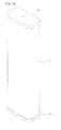
- FIG. 1a is a perspective view of a base station according to a first embodiment of the present invention
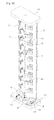
- FIG. 1b is a perspective view of the base station antenna shown in FIG. 1a , with its radome removed.
- the base station antenna according to the first embodiment of the present invention has a contour defined by a radome 412, the upper and lower portions of which are covered by upper and lower caps 411 and 413, respectively.
- a base station antenna has reflection plate connection members 44 and 45 for rotatably retaining the plurality of radiation elements 43 and 47 and the first and second reflection plates 42 and 46, as well as reflection plate rotation driving units 48, 493, and 495 for controlling rotation of the plurality of radiation elements 43 and 47 and the first and second reflection plates 42 and 46 at a remote location.
- the reflection plate rotation driving units 48, 493, and 495 include at least one power generation unit 48 and power transmission mechanism units 493 and 495.
- the reflection plate connection members 44 and 45 include a first hinge 44 fixed to the upper cap 411 and/or the lower cap 413 and a second hinge 45 mounted between the first and second reflection plates 42 and 46.
- the power generation units 48 of the reflection plate rotation driving units are configured to receive control signals from a remote location and generate power, in response to the control signals, to rotate the first and second reflection plates 42 and 46 and may be a motor, for example.
- the power transmission mechanism units 493 and 495 of the reflection plate rotation driving units include external gears 493 fixed to the rotation shafts of the power generation units 48 and internal gears 495 formed on the lower cap 413 in conformity with the path of movement of the external gears 493, which is defined by rotation of the first and second reflection plates 42 and 46.
- This structure of the power transmission mechanism units 493 and 495 enables the base station antenna according to the present invention to drive the power generation units 48 based on control signals necessary to control rotation of the first and second reflection plates 42 and 46 at a remote location and, accordingly, control the rotation angle of the first and second reflection plates 42 and 46.
- the base station antenna may further include auxiliary caps 49 for containing the power generation units 48.
- the present invention is not limited thereto, and the power transmission mechanism units 493 and 495 may be structured in any manner as long as rotation of the first and second reflection plates 42 and 46 can be controlled by rotation power provided by the power generation units 48.
- the present invention is not limited to the exemplary external and internal gears 493 and 495, which constitute the power transmission mechanism units 493 and 495 according to an embodiment of the present invention, and the power transmission mechanism units 493 and 495 may have any structure as long as rotation of the reflection plates 42 and 46 is controlled using control signals from a remote location.
- the reflection plate rotation driving units 48, 493, and 495 may be installed on the top portions of the first and second reflection plates 42 and 46.
- the base station antenna according to the first embodiment of the present invention further includes reflection plate guide units configured to support vibration reinforcement for the first and second reflection plates 42 and 46 and guide the rotation and retention of the reflection plates.
- reflection plate guide units configured to support vibration reinforcement for the first and second reflection plates 42 and 46 and guide the rotation and retention of the reflection plates.
- Detailed construction of the reflection plate guide units is exemplified in FIGs. 2, 3 , 4a, and 4b .
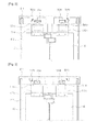
- FIG. 2 is a sectional view illustrating a first example of the reflection plate guide units
- FIG. 3 is a sectional view illustrating a second example of the reflection plate guide units
- FIGs. 4a and 4b are sectional views illustrating a third example of the reflection plate guide units.
- the first example of the reflection plate guide units 501a, 502a, 503a, 504a, 501b, 502b, 503b, and 504b may have reflection plate retention driving units 501a and 501b to have a structure similar to that of the reflection plate rotation driving units 48, 493, and 495.
- the reflection plate guide units 501a, 502a, 503a, 504a, 501b, 502b, 503b, and 504b include reflection plate retention driving units 501a and 501b coupled to the first and second reflection plates 42 and 46 through retention members 502a and 502b, respectively.
- the reflection plate guide units 501a, 502a, 503a, 504a, 501b, 502b, 503b, and 504b also include small external gears 503a and 503b and internal gears 501a and 501b.
- the small external gears 503a and 503b are coupled to rotation shafts of the reflection plate retention driving units 501a and 501b, and the internal gears 504a and 504b are formed on the upper cap 411 in conformity with the path of movement of the small external gears 503a and 503b.
- the reflection plate retention driving units 501a and 501b of the reflection plate guide units exemplified in FIG. 2 may be controlled based on interworking with control signals for controlling the power generation units 48.
- driving of the power generation units 48 of the reflection plate rotation driving units is followed by driving of the reflection plate retention driving units 501a and 501 b of the reflection plate guide units, and both the upper and lower portions of the first and second reflection plates 42 and 46 rotate at the same rate and angle.
- the reflection plate retention driving units 501a and 501b of the reflection plate guide units do not rotate either, but retain the upper position of the first and second reflection plates 42 and 46 through the small external gears 503a and 503b and the internal gears 504a and 504b.
- a second example of the reflection plate guide units may have non-excited brakes 511a and 511b as an alternative to the reflection plate retention driving units 501a and 501b of the first example.
- the reflection plate guide units 511 a, 512a, 513a, 514a, 511b, 512b, 513b, and 514b of the second example may include, in order to guide the movement of the first and second reflection plates 42 and 46, non-excited brakes 511 a and 511b retained through retention members 512a and 512b coupled to the first and second reflection plates 42 and 46, respectively, small external gears 513a and 513b coupled to rotation shafts of the non-excited brakes 511 a and 511b, and internal gears 514a and 514b formed on the upper cap 411 in conformity with the path of movement of the small external gears 513a and 513b.
- the non-excited brakes 511 a and 511b of the reflection plate guide units exemplified in FIG. 3 may be controlled based on interworking with control signals for controlling the power generation units 48. Specifically, during input of an actuation signal for rotation driving into the power generation units 48 of the reflection plate rotation driving units, the actuation signal is also inputted into the non-excited brakes 511 a and 511b of the reflection plate guide units, and the small external gears 513a and 513b, which are coupled to the non-excited brakes 511a and 511b, then enable the first and second reflection plates 42 and 46 to rotate.
- the small external gears 513a and 513b coupled to rotation shafts of the non-excited brakes 511a and 511b are enabled to rotate, and since the power generation units 48 begin driving, the first and second reflection plates 42 and 46 are guided along the path provided by the small external gears 513a and 513b and the internal gears 514a and 514b.
- the deactivation signal is also inputted to the non-excited brakes 511a and 511b of the reflection plate guide units, which then prevent the first and second reflection plates 42 and 46 from rotating.
- the small external gears 513a and 513b coupled to the non-excited brakes 511a and 511b engage with the internal gears 514a and 514b and retain the upper portion of the first and second reflection plates 42 and 46.
- a third example of the reflection plate guide units may have solenoid units 521a, 521b, 523a, and 523b, which include coil bodies 521a and 521b and retention pins 523a and 523b, as an alternative to the reflection plate retention driving units 501a and 501b of the first example.
- the third example of the reflection plate guide units 521a, 522a, 523a, 524a, 521b, 522b, 523b, and 524b have solenoid units 521 a, 521b, 523a, 523b for guiding the movement of the first and second reflection plates 42 and 46, as well as first and second retention pin reception arrays 524a and 524b.
- the solenoid units 521a, 521b, 523a, and 523b are coupled to the first and second reflection plates 42 and 46, respectively, and the first and second retention pin reception arrays 524a and 524b are provided on the upper cap 411 to retain the first and second reflection plates 42 and 46 in a rotated state.
- the first and second retention pin reception arrays 524a and 524b have the same structure, and detailed construction of the first retention pin reception array 524a will now be described with reference to FIG. 4b , without repeating the same for the second retention pin reception array 524b.
- the first retention pin reception array 524a is coupled to the upper cap 411 and has a plurality of retention holes 525a configured to receive the retention pin 523a of the solenoid units 521a, 521b, 523a, and 523b.
- the plurality of retention holes 525a are positioned to correspond to the path of rotational movement of the first reflection plate 42.
- the reflection plate guide units 521 a, 522a, 523a, 524a, 521b, 522b, 523b, and 524b are configured to operate based on interworking with control signals inputted to the power generation units 48.
- the actuation signal is inputted to the coil bodies 521 a and 521b of the solenoid units, causing a current flow.
- the retention pins 523a and 523b are then pulled toward the coil bodies 521a and 521b and withdrawn from the first and second retention pin reception arrays 524a and 524b.
- the deactivation signal is inputted to the coil bodies 521a and 521b of the solenoid units 521a, 521b, 523a, and 523b, allowing no more current flow.
- the retention pins 523a and 523b are then drawn towards the retention holes 525a and 525b of the first and second retention pin reception arrays 524a and 524b.
- 4a and 4b provides the following operation: during rotation of the power generation units 48 of the reflection plate rotation driving units, the retention pins 523a and 523b are pulled towards the coil bodies 521 a and 521b and withdrawn from the first and second retention pin reception arrays 524a and 524b, allowing the first and second reflection plates 42 and 46 to rotate freely. On the other hand, during no rotation of the power generation units 48 of the reflection plate rotation driving units, the retention pins 523a and 523b are pulled into the retention holes 525a and 525b of the first and second retention pin reception arrays 524a and 524b to retain the first and second reflection plates 42 and 46.
- the base station antenna according to the first embodiment of the present invention may further include at least one rotation limit 461 and 462 for controlling the rotation angle of the first and second reflection plates 42 and 46.
- the rotation limits 461 and 462 may be coupled to the front surface (e.g. surface on which the plurality of radiation elements 43 and 47 are mounted) and the rear surface of the first and second reflection plates 42 and 46 so as to cross each other. Specifically, at least one of the rotation limits 461 and 462 may be coupled to the front surface (e.g. surface on which the plurality of radiation elements 43 and 47 are mounted) of the second reflection plate 46, as shown in FIG. 1b , and at least one on the rear surface of the first reflection plate 42.
- a set of rotation limits 461 and 462 may be mounted on the front surfaces (e.g. surfaces on which the plurality of radiation elements 43 and 47 are mounted) of the first and second reflection plates 42 and 46, respectively, and another set on the rear surface thereof, respectively.
- the rotation limits 461 and 462 may have the shape of a circular sector or a triangle, which has an angle (e.g. inner angle of 120° ) determined to control the rotation of the first and second reflection plates 42 and 46.
- One ends of the rotation limits 461 and 462 of the above-mentioned structure are coupled to the first and second reflection plates 42 and 46, which are then allowed to rotate within a first angle range. If the first and second reflection plates 42 and 46 rotate out of a second angle range, the other ends of the rotation limits 461 and 462 contact them and prevent further rotation.
- the rotation limits 461 and 462 are coupled to the front and rear surfaces of the first and second reflection plates 42 and 46 so as to cross each other, or coupled to both the front and rear surfaces thereof, and have the shape of a circular sector or a triangle according to the first embodiment of the present invention
- the present invention is not limited to the exemplary structure of the rotation limits, the coupling position or shape of which can be modified variously as long as they can limit the rotation angle of the first and second reflection plates 42 and 46.
- FIGs. 5a to 5e exemplify beam patterns radiated from the base station antenna shown in FIG. 1b , as well as their directions.
- the reflection plates 42 and 46 of the base station antenna according to the first embodiment of the present invention, as described above, can rotate as shown in FIGs. 5a to 5e .
- the base station antenna according to the present invention can support an inter-sector load balancing function, direct antenna beams to a hotspot area within the service area, and variously modify the section management of the base station.
- FIG. 6 is a perspective view of a base station antenna according to a second embodiment of the present invention
- FIGs. 7a to 7e illustrate exemplary beam patterns, which are radiated from the base station antenna shown in FIG. 6 , and directions.
- the base station antenna according to the second embodiment of the present invention has the same structure as the base station antenna according to the first embodiment, except for a difference in the number of reflection plates inside the radome 612 and the construction of equipment for rotation of the reflection plates.
- the base station antenna has three reflection plates, i.e. first, second, and third plates 62, 64, and 66 inside the radome 612.
- the second and third reflection plates 64 and 66 are positioned on both sides, respectively, and are connected to the first reflection plate 62 through reflection plate connection members 68 and 69, respectively.
- the reflection plate connection members 68 and 69 are configured to retain the position of the first reflection plate 62 and to allow the second and third reflection plates 64 and 66 to rotate about center shafts of the reflection plate connection members 68 and 69.
- the base station antenna further includes, in order to control rotation of the second and third reflection plates 64 and 66 at a remote location, power generation units 705 and power transmission mechanism units 713 and 715.
- the power transmission mechanism units 713 and 715 may include, as in the case of the first embodiment, external gears 713 and internal gears 715.
- the power transmission mechanism units 713 and 715 may further include auxiliary caps 70 for containing the power generation units 705, and the auxiliary caps 70 may be mounted on the second and third reflection plates 64 and 66, respectively.
- the above-mentioned structure of the power generation units 705 and the power transmission mechanism units 713 and 715 enables the base station antenna to receive signals to control the power generation units 705, which are necessary to control rotation of the second and third reflection plates 64 and 66, from a remote location and, based on driving of the power generation units 705, control the rotation angle of the second and third reflection plates 64 and 66.
- the second and third reflection plates 64 and 66 can be rotated by the power generation units 705 as shown in FIGs. 7a to 7e .
- the base station antenna according to the second embodiment further includes reflection plate guide units configured to support vibration reinforcement for the reflection plates 62, 64, and 66 and to guide the rotation and retention of the reflection plates 62, 64, and 66.
- the reflection plate guide units may have a construction and a structure similar to those of the reflection plate guide units of the base station antenna according to the first embodiment. Therefore, the structure of the reflection plate guide units according to the first embodiment will be referred to, instead of describing the same again.
- the base station antenna according to the second embodiment of the present invention may further include at least one rotation limit 661, 662, 663, and 664 to determine the rotation angle of the first, second, and third reflection plates 62, 64, and 66.
- rotation limits 661, 662, 663, and 664 can be modified variously as long as it can control the rotation angle of the second and third reflection plates 64 and 66.
- the above-mentioned structure of the base station antenna according to the second embodiment of the present invention makes it possible to simultaneously emit signals for providing different communication services through the first, second, and third reflection plates 62, 64, and 66.
- 2G (or 3G) and 4G communication services are provided in a co-siting manner
- it is possible to emit signals for providing the 2G (or 3G) communication service through the first reflection plate 62 and emit signals for providing the 4G communication service through the second and third reflection plates 64 and 64. Therefore, the base station antenna according to the second embodiment of the present invention has a considerable merit when a 2G (or 3G) communication service is still provided and a 4G network is newly constructed in a co-siting manner.
- the existing 2G (or 3G) communication antenna is retained at the center, and new 4G communication antennas are provided on both sides.
- This can reduce signal correlation to a suitable level and create a proper level of space diversity.
- the mechanism-based adjustment of the radiation direction of antenna beams by the power generation units 705 and the power transmission mechanism units 713 and 715 creates a pattern diversity effect.
- the base station antenna according to the second embodiment of the present invention can, even if the newly designed communication network (e.g. 4G communication service network) differs from the previous communication network (e. g. 3G communication service network), operate the co-siting flexibly through control of beam radiation direction.
- HMAT Hybrid Multiple Antenna Technology
- the optimized operation of mobile communication networks means that signal processing related to individual subscribers is performed in the baseband, and antenna beam formation based on subscriber distribution is performed by the base station antenna according to the present invention.
- control of the directing angle of a plurality of reflection plates inside one radome at a remote location makes it possible to reflect the condition of communication environments in real time, to perform a load balancing function accordingly, and to direct antenna beams towards a hotspot area without any limitation on space and time.
- reflection plates provided inside one radome are operated as antennas for different service networks so that co-siting is possible, i.e. different services can be provided simultaneously.
- antenna configuration is modified in response to wave propagation environment and subscriber distribution, thereby increasing cell capacity.
Landscapes
- Engineering & Computer Science (AREA)
- Computer Networks & Wireless Communication (AREA)
- Variable-Direction Aerials And Aerial Arrays (AREA)
- Aerials With Secondary Devices (AREA)
- Details Of Aerials (AREA)
Abstract
Description
- The present invention relates to a base station antenna, and more particularly to a base station antenna supporting multiple antenna schemes.
- Development of mobile communication technology is followed by expectations that, even before the 3G (3rd Generation) networks are saturated, 4G (4th Generation) networks will be constructed widely. One of international standards representing the 4G networks, i.e. Mobile WiMAX or LTE (Long Term Evolution) communication scheme, applies various technologies to increase the transmission rate per frequency band, i.e. capacity (bps/Hz), and, for the purpose of the most effective capacity increase, applies multiple antenna technology referred to as MIMO (Multi-Input Multi-Output).
- The essentials of multiple antenna technology for base station antennas are based on baseband signal processing technology. However, the degree of capacity increase, when multiple antennas are used, heavily depends on the antenna configuration. The reason is as follows: the multiple antenna technology makes active use of a number of multi-path fading and, at the same time, seeks to remove interference signals from other subscribers. This means that, even if the antenna configuration is the same, the degree of capacity increase varies depending on the wave propagation environment and subscriber distribution of the area covered by the base station. Therefore, international standards do not include particulars regarding the antenna configuration and allow free installation of antennas, based on field situations, to maximize the capacity.
- However, conventional multiple antenna technologies have a limitation in that, since the antenna beam is fixed, capacity increase can not be expected, once installation is completed, in adaptive response to the wave propagation environment and subscriber distribution, but solely by using baseband signal processing technology. If necessary, the operator may, for example, climb the tower and modify the antennas themselves or their configuration. However, this approach requires a large amount of time and budget for modification and optimization and cannot easily handle situations having time-varying wave propagation environment and subscriber distribution. In summary, conventional antenna technologies cannot reflect the condition of communication environment in real time to perform load balancing, and provide no method for directing the antenna beam towards a hotspot area at a remote location.
- Accordingly, the present invention has been made to solve the above-stated problems occurring in the prior art, and the present invention provides a base station antenna capable of variously modifying the radiation direction of antenna beams at a remote location in response to wave propagation environment and subscriber distribution.
- Further, the present invention provides a base station antenna capable of increasing cell capacity by modifying the antenna configuration in response to wave propagation environment and subscriber distribution.
- Further, the present invention provides a base station antenna capable of reflecting the condition of communication environments in real time, performing a load balancing function accordingly, and directing antenna beams towards a hotspot area.
- Further, the present invention provides a base station antenna configured to prevent distortion of its upper or lower portion during antenna angle modification.
- In accordance with an aspect of the present invention, there is provided a base station antenna including: at least two reflection plates each having at least one radiation element; a radome forming an internal cavity and containing the at least two reflection plates; first and second caps coupled to cover openings formed on upper and lower portions of the radome, respectively; a reflection plate connection member connected to each of the at least two reflection plates and to the first and second caps so that the at least two reflection plates can rotate; a reflection plate rotation driving unit including at least one power generation unit configured to provide rotation power and at least one power transmission mechanism unit configured to provide at least one reflection plate with rotation power from the power generation unit and control the rotation angle of the reflection plate provided with the rotation power, one of the power generation unit and the power transmission mechanism unit being coupled to the at least two reflection plates, and the other being coupled to the first cap; a reflection plate retention unit coupled to the at least two reflection plates and to the second cap to guide rotation and retention of the reflection plates; and a reflection plate control unit configured to provide the reflection plate rotation driving unit and the reflection plate retention unit with a control signal for controlling rotation and standstill of the at least two reflection plates.
- The above and other aspects, features and advantages of the present invention will be more apparent from the following detailed description taken in conjunction with the accompanying drawings, in which:
-
FIG. 1a is a perspective view of a base station antenna according to a first embodiment of the present invention; -
FIG. 1b is a perspective view of the base station antenna shown inFIG. 1a , with its radome removed; -
FIG. 2 is a sectional view illustrating a first example of reflection plate guide units of the base station antenna according to the first embodiment of the present invention; -
FIG. 3 is a sectional view illustrating a second example of reflection plate guide units of the base station antenna according to the first embodiment of the present invention; -
FIG. 4a is a sectional view illustrating a third example of reflection plate guide units of the base station antenna according to the first embodiment of the present invention; -
FIG. 4b is a partial top view of the upper cap, to which first and second retention units are coupled, shown inFIG. 4a ; -
FIGs. 5a to 5e illustrate exemplary beam patterns, which are radiated from the base station antenna shown inFIG. 1 , and their directions; -
FIG. 6 is a perspective view of a base station antenna according to a second embodiment of the present invention; and -
FIGs. 7a to 7e illustrate exemplary beam patterns, which are radiated from the base station antenna shown inFIG. 6 , and their directions. - Hereinafter, the exemplary embodiments of the present invention will be described with reference to the accompanying drawings in detail. Further, various specific definitions found in the following description are provided only to help general understanding of the present invention, and it will be understood by those skilled in the art that various changes and modifications can be made thereto within the technical spirit and scope of the present invention. In the following description, a detailed explanation of known related functions and constitutions may be omitted to avoid unnecessarily obscuring the subject matter of the present invention.
- Construction of a new communication service network (e.g. 4G network), while an existing communication service network (e.g. 2G or 3G network) is still being used to provide a mobile communication service, requires installation of a new base station site at a high cost. Therefore, construction of a new communication service network (e.g. 4G) using a site, which has an existing communication service network (e.g. 2G or 3G) installed therein, reduces the cost to install a new base station site. This means that construction of a new communication service network requires co-siting installation. More specifically, antennas necessary for the next-generation communication service network need to be installed together with antennas of the previously-constructed base station tower.
- The present invention proposes a base station antenna which forms remotely-controllable antenna beams and adaptively modifies them in conformity with wave propagation environment and subscriber distribution, thereby maximizing capacity increase through multiple antenna technology. In addition, the direction of antenna beams is adjusted based on subscriber distribution to support an inter-sector load balancing function, the antenna beams can be directed towards a hotspot area within the service area, and, when the antenna angle is modified to direct the antenna beams, distortion of the upper or lower portion of the antenna is prevented.
-
FIG. 1a is a perspective view of a base station according to a first embodiment of the present invention, andFIG. 1b is a perspective view of the base station antenna shown inFIG. 1a , with its radome removed. - Referring to
FIG. 1a , the base station antenna according to the first embodiment of the present invention has a contour defined by aradome 412, the upper and lower portions of which are covered by upper andlower caps - Referring to
FIG. 1b , inside theradome 412 are installed a plurality ofradiation elements first reflection plate 42, asecond reflection plate 46, and various types of equipment for retaining the plurality ofradiation elements second reflection plates plate connection members radiation elements second reflection plates rotation driving units radiation elements second reflection plates rotation driving units power generation unit 48 and powertransmission mechanism units - The reflection
plate connection members first hinge 44 fixed to theupper cap 411 and/or thelower cap 413 and asecond hinge 45 mounted between the first andsecond reflection plates - The
power generation units 48 of the reflection plate rotation driving units are configured to receive control signals from a remote location and generate power, in response to the control signals, to rotate the first andsecond reflection plates - The power
transmission mechanism units external gears 493 fixed to the rotation shafts of thepower generation units 48 andinternal gears 495 formed on thelower cap 413 in conformity with the path of movement of theexternal gears 493, which is defined by rotation of the first andsecond reflection plates transmission mechanism units power generation units 48 based on control signals necessary to control rotation of the first andsecond reflection plates second reflection plates auxiliary caps 49 for containing thepower generation units 48. - Those skilled in the art can understand that, although components of the power
transmission mechanism units second reflection plates transmission mechanism units second reflection plates power generation units 48. - In addition, the present invention is not limited to the exemplary external and
internal gears transmission mechanism units transmission mechanism units reflection plates - According to another embodiment of the present invention, the reflection plate
rotation driving units second reflection plates - The base station antenna according to the first embodiment of the present invention further includes reflection plate guide units configured to support vibration reinforcement for the first and
second reflection plates FIGs. 2, 3 ,4a, and 4b . -
FIG. 2 is a sectional view illustrating a first example of the reflection plate guide units,FIG. 3 is a sectional view illustrating a second example of the reflection plate guide units, andFIGs. 4a and 4b are sectional views illustrating a third example of the reflection plate guide units. - Referring to
FIG. 2 , the first example of the reflectionplate guide units retention driving units rotation driving units plate guide units retention driving units second reflection plates retention members plate guide units external gears internal gears external gears retention driving units internal gears upper cap 411 in conformity with the path of movement of the smallexternal gears retention driving units FIG. 2 may be controlled based on interworking with control signals for controlling thepower generation units 48. Specifically, driving of thepower generation units 48 of the reflection plate rotation driving units is followed by driving of the reflection plateretention driving units second reflection plates power generation units 48 of the reflection plate rotation driving units do not rotate and the powertransmission mechanism units second reflection plates retention driving units second reflection plates external gears internal gears - A second example of the reflection plate guide units, as shown in
FIG. 3 , may havenon-excited brakes 511a and 511b as an alternative to the reflection plateretention driving units plate guide units second reflection plates non-excited brakes 511 a and 511b retained throughretention members second reflection plates external gears non-excited brakes 511 a and 511b, andinternal gears upper cap 411 in conformity with the path of movement of the smallexternal gears - The
non-excited brakes 511 a and 511b of the reflection plate guide units exemplified inFIG. 3 may be controlled based on interworking with control signals for controlling thepower generation units 48. Specifically, during input of an actuation signal for rotation driving into thepower generation units 48 of the reflection plate rotation driving units, the actuation signal is also inputted into thenon-excited brakes 511 a and 511b of the reflection plate guide units, and the smallexternal gears non-excited brakes 511a and 511b, then enable the first andsecond reflection plates external gears non-excited brakes 511a and 511b are enabled to rotate, and since thepower generation units 48 begin driving, the first andsecond reflection plates external gears internal gears power generation units 48 of the reflection plate rotation driving units, the deactivation signal is also inputted to thenon-excited brakes 511a and 511b of the reflection plate guide units, which then prevent the first andsecond reflection plates external gears non-excited brakes 511a and 511b engage with theinternal gears second reflection plates - A third example of the reflection plate guide units, as shown in
FIG. 4a , may havesolenoid units coil bodies retention pins retention driving units - The third example of the reflection
plate guide units units second reflection plates pin reception arrays solenoid units second reflection plates pin reception arrays upper cap 411 to retain the first andsecond reflection plates pin reception arrays pin reception array 524a will now be described with reference toFIG. 4b , without repeating the same for the second retentionpin reception array 524b. The first retentionpin reception array 524a is coupled to theupper cap 411 and has a plurality ofretention holes 525a configured to receive theretention pin 523a of thesolenoid units retention holes 525a are positioned to correspond to the path of rotational movement of thefirst reflection plate 42. - The reflection
plate guide units power generation units 48. To be specific, during input of an actuation signal for rotation driving into thepower generation units 48 of the reflection plate rotation driving units, the actuation signal is inputted to thecoil bodies coil bodies pin reception arrays power generation units 48 of the reflection plate rotation driving units, the deactivation signal is inputted to thecoil bodies solenoid units retention holes pin reception arrays plate guide units FIGs. 4a and 4b provides the following operation: during rotation of thepower generation units 48 of the reflection plate rotation driving units, theretention pins coil bodies pin reception arrays second reflection plates power generation units 48 of the reflection plate rotation driving units, theretention pins retention holes pin reception arrays second reflection plates - Referring to
FIG. 1b again, the base station antenna according to the first embodiment of the present invention may further include at least onerotation limit second reflection plates - The rotation limits 461 and 462 may be coupled to the front surface (e.g. surface on which the plurality of
radiation elements second reflection plates radiation elements second reflection plate 46, as shown inFIG. 1b , and at least one on the rear surface of thefirst reflection plate 42. - Alternatively, a set of
rotation limits radiation elements second reflection plates - The rotation limits 461 and 462 may have the shape of a circular sector or a triangle, which has an angle (e.g. inner angle of 120° ) determined to control the rotation of the first and
second reflection plates - One ends of the rotation limits 461 and 462 of the above-mentioned structure are coupled to the first and
second reflection plates second reflection plates - Those skilled in the art can understand that, although the rotation limits 461 and 462 are coupled to the front and rear surfaces of the first and
second reflection plates second reflection plates -
FIGs. 5a to 5e exemplify beam patterns radiated from the base station antenna shown inFIG. 1b , as well as their directions. Thereflection plates FIGs. 5a to 5e . Furthermore, the base station antenna according to the present invention can support an inter-sector load balancing function, direct antenna beams to a hotspot area within the service area, and variously modify the section management of the base station. -
FIG. 6 is a perspective view of a base station antenna according to a second embodiment of the present invention, andFIGs. 7a to 7e illustrate exemplary beam patterns, which are radiated from the base station antenna shown inFIG. 6 , and directions. - The base station antenna according to the second embodiment of the present invention has the same structure as the base station antenna according to the first embodiment, except for a difference in the number of reflection plates inside the
radome 612 and the construction of equipment for rotation of the reflection plates. - To be specific, the base station antenna according to the second embodiment has three reflection plates, i.e. first, second, and
third plates radome 612. With thefirst reflection plate 62 at the center, the second andthird reflection plates first reflection plate 62 through reflectionplate connection members plate connection members first reflection plate 62 and to allow the second andthird reflection plates plate connection members - The base station antenna further includes, in order to control rotation of the second and
third reflection plates power generation units 705 and powertransmission mechanism units transmission mechanism units external gears 713 andinternal gears 715. - The power
transmission mechanism units auxiliary caps 70 for containing thepower generation units 705, and theauxiliary caps 70 may be mounted on the second andthird reflection plates - The above-mentioned structure of the
power generation units 705 and the powertransmission mechanism units power generation units 705, which are necessary to control rotation of the second andthird reflection plates power generation units 705, control the rotation angle of the second andthird reflection plates third reflection plates power generation units 705 as shown inFIGs. 7a to 7e . - The base station antenna according to the second embodiment further includes reflection plate guide units configured to support vibration reinforcement for the
reflection plates reflection plates - The base station antenna according to the second embodiment of the present invention may further include at least one
rotation limit third reflection plates third reflection plates - The above-mentioned structure of the base station antenna according to the second embodiment of the present invention makes it possible to simultaneously emit signals for providing different communication services through the first, second, and
third reflection plates first reflection plate 62 and emit signals for providing the 4G communication service through the second andthird reflection plates power generation units 705 and the powertransmission mechanism units - Furthermore, proper association of the base station antenna according to the present invention with baseband signal processing technology and combined operation can lead to evolution to HMAT (Hybrid Multiple Antenna Technology), which provides optimized operation of mobile communication networks. The optimized operation of mobile communication networks, in this connection, means that signal processing related to individual subscribers is performed in the baseband, and antenna beam formation based on subscriber distribution is performed by the base station antenna according to the present invention.
- The base station antenna according to the present invention has the following advantageous effects:
- First, control of the directing angle of a plurality of reflection plates inside one radome at a remote location makes it possible to reflect the condition of communication environments in real time, to perform a load balancing function accordingly, and to direct antenna beams towards a hotspot area without any limitation on space and time.
- Second, reflection plates provided inside one radome are operated as antennas for different service networks so that co-siting is possible, i.e. different services can be provided simultaneously.
- Third, antenna configuration is modified in response to wave propagation environment and subscriber distribution, thereby increasing cell capacity.
- Fourth, during modification of the antenna directing angle, distortion of the upper or lower portion of the antenna is prevented.
- While the present invention has been shown and described with reference to certain exemplary embodiments and drawings thereof, it will be understood by those skilled in the art that various changes in form and details may be made therein without departing from the spirit and scope of the invention as defined by the appended claims.
Claims (14)
- A base station antenna comprising:at least two reflection plates each having at least one radiation element;a radome forming an internal cavity and containing the at least two reflection plates;first and second caps coupled to cover openings formed on upper and lower portions of the radome, respectively;a reflection plate connection member connected to each of the at least two reflection plates and to the first and second caps so that the at least two reflection plates can rotate;a reflection plate rotation driving unit comprising at least one power generation unit configured to provide rotation power and at least one power transmission mechanism unit configured to provide at least one reflection plate with rotation power from the power generation unit and control the rotation angle of the reflection plate provided with the rotation power, one of the power generation unit and the power transmission mechanism unit being coupled to the at least two reflection plates, and the other being coupled to the first cap;a reflection plate retention unit coupled to the at least two reflection plates and to the second cap to guide rotation and retention of the reflection plates; anda reflection plate control unit configured to provide the reflection plate rotation driving unit and the reflection plate retention unit with a control signal for controlling rotation and standstill of the at least two reflection plates.
- The base station antenna as claimed in claim 1, wherein the reflection plate retention unit comprises:at least one auxiliary power generation unit configured to provide rotation power in response to the control signal; andat least one auxiliary power transmission mechanism unit configured to provide at least one reflection plate with rotation power from the auxiliary power generation unit and control the rotation angle of the reflection plate provided with the rotation power.
- The base station antenna as claimed in claim 2, wherein the auxiliary power transmission mechanism unit comprises at least one external gear mounted on one side of the auxiliary power generation unit and an internal gear provided on the first cap along a movement radius of the at least one external gear.
- The base station antenna as claimed in claim 1, wherein the reflection plate retention unit comprises:a reflection plate retention driving unit controlled to retain the reflection plates onto the second cap, in response to the control signal, while the power generation unit provides no rotation power; andat least one reflection plate retention mechanism unit configured to maintain the reflection plates and the second cap in a retained condition.
- The base station antenna as claimed in claim 4, wherein the reflection plate retention driving unit comprises a non-excited brake configured to retain the reflection plates while the power generation unit provides no rotation power, and
the reflection plate retention mechanism unit comprises at least one external gear coupled to the non-excited brake and an internal gear provided on the second cap along the movement radius of the at least one external gear. - The base station antenna as claimed in claim 4, wherein the reflection plate retention driving unit comprises a solenoid unit having a retention pin configured to protrude while the power generation unit provides no rotation power, and
the reflection plate retention mechanism unit comprises a retention pin reception array having at least one hole formed to receive the retention pin and retain positions of the reflection plates. - The base station antenna as claimed in claim 1, wherein the power transmission mechanism unit comprises at least one external gear mounted on one side of the power generation unit and an internal gear provided on the first cap along a movement radius of the at least one external gear.
- The base station antenna as claimed in claim 1, further comprising a rotation limit coupled to at least one of the at least two reflection plates to control the rotation angle of the at least two reflection plates.
- The base station antenna as claimed in claim 1, further comprising at least two rotation limits coupled to the at least two reflection plates, respectively, to control the rotation angle of the at least two reflection plates.
- The base station antenna as claimed in claim 8, wherein the rotation limit comprises:first limits coupled to front portions of the reflection plates to control the front rotation angle of the reflection plates; andsecond limits coupled to rear portions of the reflection plates to control the rear rotation angle of the reflection plates.
- The base station antenna as claimed in claim 10, wherein one ends of the first and second limits are fixed to the at least one reflection plate, and, during rotation of the reflection plate, other ends of the first and second limits contact the other reflection plate adjacent to the at least one reflection plate so that rotation of the reflection plates is controlled.
- The base station antenna as claimed in any one of claims 1-11, wherein the base station antenna comprises a first reflection plate positioned at the center and second and third reflection plates positioned on both sides of the first reflection plate, respectively,
the first reflection plate has a fixed beam radiation direction, and
the second and third reflection plates have a radiation angle adjusted by the power generation unit and the power transmission mechanism unit. - A base station antenna comprising:at least one power generation unit configured to provide rotation power;at least one power transmission mechanism unit configured to provide at least one reflection plate with rotation power from the power generation unit and control the rotation angle of the at least one reflection plate provided with the rotation power; anda reflection plate retention unit coupled to the at least one reflection plate and to at least one of caps mounted on upper and lower portions of an antenna radome, respectively, to retain the at least one reflection plate, whereinone of the power generation unit and the power transmission mechanism unit is coupled to the at least one reflection plate, and the other is coupled to the cap.
- The base station antenna as claimed in claim 13, wherein the reflection plate retention unit is configured to retain the at least one reflection plate while no rotation power is being provided and is implemented by one selected from the group consisting of a motor, a non-excited brake, and a solenoid unit.
Applications Claiming Priority (2)
| Application Number | Priority Date | Filing Date | Title |
|---|---|---|---|
| KR1020090128482A KR101085890B1 (en) | 2009-12-21 | 2009-12-21 | Base station antenna with shape change |
| PCT/KR2010/009175 WO2011078565A2 (en) | 2009-12-21 | 2010-12-21 | Reconfigurable base station antenna |
Publications (3)
| Publication Number | Publication Date |
|---|---|
| EP2518829A4 EP2518829A4 (en) | 2012-10-31 |
| EP2518829A2 true EP2518829A2 (en) | 2012-10-31 |
| EP2518829B1 EP2518829B1 (en) | 2015-03-04 |
Family
ID=44196304
Family Applications (1)
| Application Number | Title | Priority Date | Filing Date |
|---|---|---|---|
| EP10839762.1A Active EP2518829B1 (en) | 2009-12-21 | 2010-12-21 | Reconfigurable base station antenna |
Country Status (9)
| Country | Link |
|---|---|
| US (1) | US8743008B2 (en) |
| EP (1) | EP2518829B1 (en) |
| JP (1) | JP5456173B2 (en) |
| KR (1) | KR101085890B1 (en) |
| CN (1) | CN102656745B (en) |
| AU (1) | AU2010335180B2 (en) |
| BR (1) | BR112012015518B1 (en) |
| NZ (1) | NZ600185A (en) |
| WO (1) | WO2011078565A2 (en) |
Cited By (1)
| Publication number | Priority date | Publication date | Assignee | Title |
|---|---|---|---|---|
| EP2819241A3 (en) * | 2013-06-07 | 2015-06-24 | Orange Polska S.A. | Adaptive antenna and a method of controlling an adaptive antenna beam |
Families Citing this family (52)
| Publication number | Priority date | Publication date | Assignee | Title |
|---|---|---|---|---|
| PL3199300T3 (en) | 2010-07-12 | 2020-09-21 | Saint-Gobain Abrasives, Inc. | Abrasive article for shaping of industrial materials |
| KR101869756B1 (en) | 2012-04-12 | 2018-06-21 | 주식회사 케이엠더블유 | Adjustable beam antenna for mobile communication system |
| USD697900S1 (en) * | 2012-07-18 | 2014-01-21 | Kmw Inc. | Antenna radome |
| ES2862457T3 (en) * | 2012-11-16 | 2021-10-07 | Kmw Inc | Small size base station device in a mobile communication system |
| US9368880B2 (en) * | 2012-11-16 | 2016-06-14 | Alcatel Lucent | Multi-sector antenna structure |
| KR20140109712A (en) * | 2013-03-06 | 2014-09-16 | 주식회사 케이엠더블유 | Horizontal array with the antenna radiating elements |
| KR102074918B1 (en) * | 2014-02-04 | 2020-03-02 | 삼성전자주식회사 | Adaptable antenna apparatus for base station |
| US9747479B2 (en) | 2014-08-07 | 2017-08-29 | Dirac Solutions, Inc. | Smart passive RFID reader with adaptive beamforming capability |
| KR200482343Y1 (en) * | 2014-09-05 | 2017-01-13 | 주식회사 케이엠더블유 | Antenna apparatus for mobile communication system |
| WO2016181582A1 (en) * | 2015-05-14 | 2016-11-17 | 株式会社東芝 | Electronic machine and manufacturing method therefor |
| WO2017091307A1 (en) * | 2015-11-25 | 2017-06-01 | Commscope Technologies Llc | Phased array antennas having decoupling units |
| KR101769404B1 (en) * | 2016-01-22 | 2017-08-21 | 주식회사 케이엠더블유 | Base station apparatus integrated with antenna for mobile communication network and antenna fixing device |
| CN105703080A (en) * | 2016-03-23 | 2016-06-22 | 武汉虹信通信技术有限责任公司 | Multi-system and multi-port base station antenna common reflection board |
| CN106229681A (en) * | 2016-08-31 | 2016-12-14 | 广东通宇通讯股份有限公司 | Two-dimensional electric tilt antenna drive mechanism |
| WO2018140305A1 (en) * | 2017-01-24 | 2018-08-02 | Commscope Technologies Llc | Base station antennas including supplemental arrays |
| KR101899928B1 (en) * | 2017-01-26 | 2018-09-18 | 주식회사 케이엠더블유 | Antenna Assembly |
| US10985454B2 (en) | 2017-06-15 | 2021-04-20 | Commscope Technologies Llc | Base station antennas having bottom end caps with angled connector ports |
| GB2572769B (en) | 2018-04-09 | 2022-12-14 | Airspan Ip Holdco Llc | Moveable antenna apparatus |
| EP3861592B1 (en) | 2018-10-05 | 2025-12-24 | Outdoor Wireless Networks LLC | Reconfigurable multi-band base station antennas having self-contained sub-modules |
| CN110838622B (en) * | 2019-01-30 | 2023-02-28 | 新华三技术有限公司 | Antenna system and network equipment |
| CN111525235A (en) * | 2019-02-02 | 2020-08-11 | 康普技术有限责任公司 | Multiband Base Station Antenna |
| CN111613894B (en) * | 2019-02-25 | 2021-08-06 | Oppo广东移动通信有限公司 | Antenna assembly, electronic device and antenna performance adjustment method |
| WO2020190863A1 (en) | 2019-03-21 | 2020-09-24 | Commscope Technologies Llc | Base station antennas having parasitic assemblies for improving cross-polarization discrimination performance |
| CN111478019A (en) * | 2019-04-28 | 2020-07-31 | 李玮 | V-shaped electric-tuning mobile communication antenna |
| CN112437998B (en) * | 2019-06-25 | 2023-07-18 | 康普技术有限责任公司 | Multi-beam base station antenna with broadband radiating elements |
| CN112186367A (en) * | 2019-07-03 | 2021-01-05 | 康普技术有限责任公司 | Base station antenna |
| CN112186330A (en) * | 2019-07-03 | 2021-01-05 | 康普技术有限责任公司 | Base station antenna |
| GB2587411B (en) * | 2019-09-27 | 2024-01-03 | Francis & Lewis International Ltd | Antenna mounting device and system |
| US11289798B2 (en) | 2020-02-24 | 2022-03-29 | Commscope Technologies Llc | Connectivity and field replaceability of radios mounted on base station antennas |
| US11611143B2 (en) | 2020-03-24 | 2023-03-21 | Commscope Technologies Llc | Base station antenna with high performance active antenna system (AAS) integrated therein |
| EP4429025A3 (en) | 2020-03-24 | 2024-11-20 | Outdoor Wireless Networks LLC | Radiating elements having angled feed stalks and base station antennas including same |
| EP3966898A4 (en) | 2020-03-24 | 2023-01-25 | CommScope Technologies LLC | ACTIVE ANTENNA MODULE BASE STATION ANTENNAS AND RELATED DEVICES AND METHODS |
| US12218425B2 (en) | 2020-04-28 | 2025-02-04 | Outdoor Wireless Networks LLC | Base station antennas having reflector assemblies including a nonmetallic substrate having a metallic layer thereon |
| US11581637B2 (en) * | 2020-09-21 | 2023-02-14 | Commscope Technologies Llc | Adjustable reflector antennas |
| EP4218093B1 (en) * | 2020-09-27 | 2025-08-20 | Telefonaktiebolaget LM Ericsson (publ) | A mobile communication antenna |
| CN116325363B (en) * | 2020-10-12 | 2025-02-21 | 华为技术有限公司 | Multi-band common-caliber antenna and communication equipment |
| CN116724465B (en) * | 2020-12-28 | 2025-09-09 | 华为技术有限公司 | Base station antenna |
| CN112821082B (en) * | 2021-01-04 | 2022-04-19 | 武汉虹信科技发展有限责任公司 | Antenna with adjustable horizontal lobe width and base station |
| KR20220117810A (en) | 2021-02-17 | 2022-08-24 | 한국전자통신연구원 | Method and apparatus for the directive direction finding |
| CN215418610U (en) | 2021-08-31 | 2022-01-04 | 康普技术有限责任公司 | Frequency selective reflector and base station antenna |
| CN115911820A (en) * | 2021-09-22 | 2023-04-04 | 安弗施无线射频系统(上海)有限公司 | Antennas and base stations |
| TWI828161B (en) * | 2022-05-24 | 2024-01-01 | 萬旭電業股份有限公司 | Multi-beam antenna module |
| CN117199772A (en) | 2022-06-01 | 2023-12-08 | 康普技术有限责任公司 | Base station antenna |
| US12469960B2 (en) | 2022-07-08 | 2025-11-11 | Outdoor Wireless Networks LLC | Base station antennas |
| US12021304B2 (en) | 2022-07-14 | 2024-06-25 | Wanshih Electronic Co., Ltd. | Multi-beam antenna module |
| TWI844070B (en) * | 2022-08-08 | 2024-06-01 | 啟碁科技股份有限公司 | Antenna rotation structure and electronic device |
| JP2025540604A (en) * | 2022-11-04 | 2025-12-16 | テレフオンアクチーボラゲット エルエム エリクソン(パブル) | Radio Assembly Repairability |
| CN118040288A (en) * | 2022-11-11 | 2024-05-14 | 康普技术有限责任公司 | Base station antenna system with adjustable reflector in a cylindrical radome |
| CN118213758A (en) * | 2022-12-16 | 2024-06-18 | 华为技术有限公司 | Base station antenna and base station |
| CN118263661A (en) * | 2022-12-26 | 2024-06-28 | 上海华为技术有限公司 | Antenna system and communication device |
| CN115842244A (en) * | 2022-12-27 | 2023-03-24 | 京信通信技术(广州)有限公司 | Antenna angle adjusting equipment, antenna and base station |
| CN117374563B (en) * | 2023-11-22 | 2025-11-11 | 京信通信技术(广州)有限公司 | Base station antenna |
Family Cites Families (18)
| Publication number | Priority date | Publication date | Assignee | Title |
|---|---|---|---|---|
| DE3043611C2 (en) | 1980-11-19 | 1984-07-05 | Messerschmitt-Bölkow-Blohm GmbH, 8000 München | Rotary positionable system |
| JPS6049305A (en) | 1983-08-30 | 1985-03-18 | Mitsubishi Electric Corp | Optical distributor |
| US5111214A (en) * | 1986-10-10 | 1992-05-05 | Hazeltine Corporation | Linear array antenna with E-plane backlobe suppressor |
| NZ235010A (en) * | 1990-08-22 | 1993-12-23 | Deltec New Zealand | Dipole panel antenna with electrically tiltable beam. |
| US5469181A (en) * | 1994-03-18 | 1995-11-21 | Celwave | Variable horizontal beamwidth antenna having hingeable side reflectors |
| KR0185962B1 (en) * | 1995-03-03 | 1999-05-15 | 구관영 | Antenna |
| US5724051A (en) * | 1995-12-19 | 1998-03-03 | Allen Telecom Inc. | Antenna assembly |
| JP2885172B2 (en) | 1996-03-21 | 1999-04-19 | 日本電気株式会社 | CS antenna mounting method and device |
| US8018390B2 (en) | 2003-06-16 | 2011-09-13 | Andrew Llc | Cellular antenna and systems and methods therefor |
| US7015871B2 (en) * | 2003-12-18 | 2006-03-21 | Kathrein-Werke Kg | Mobile radio antenna arrangement for a base station |
| KR100713202B1 (en) | 2003-12-23 | 2007-05-02 | 주식회사 케이엠더블유 | Mobile communication base station antenna beam control device |
| JP4203444B2 (en) * | 2004-05-06 | 2009-01-07 | パイオニア株式会社 | Composite speaker device |
| KR100774262B1 (en) * | 2005-11-08 | 2007-11-08 | (주)에이스안테나 | Beam direction variable device of mobile communication base station antenna |
| KR100807321B1 (en) | 2005-12-13 | 2008-02-28 | 주식회사 케이엠더블유 | Adjustable beam antenna for mobile communication base station |
| JP2009533010A (en) | 2006-04-06 | 2009-09-10 | アンドリュー・コーポレーション | Cellular antenna and system and method therefor |
| US20090135076A1 (en) * | 2007-11-28 | 2009-05-28 | Senglee Foo | Linear antenna array with azimuth beam augmentation by axial rotation |
| KR20090130812A (en) * | 2008-06-16 | 2009-12-24 | 주식회사 케이엠더블유 | Base station antenna with shape change |
| JP5261328B2 (en) | 2009-09-02 | 2013-08-14 | 有限会社オンサイト計画設計事務所 | Floor structure |
-
2009
- 2009-12-21 KR KR1020090128482A patent/KR101085890B1/en active Active
-
2010
- 2010-12-21 BR BR112012015518-0A patent/BR112012015518B1/en active IP Right Grant
- 2010-12-21 CN CN201080058621.5A patent/CN102656745B/en active Active
- 2010-12-21 US US13/517,088 patent/US8743008B2/en active Active
- 2010-12-21 WO PCT/KR2010/009175 patent/WO2011078565A2/en not_active Ceased
- 2010-12-21 NZ NZ600185A patent/NZ600185A/en unknown
- 2010-12-21 EP EP10839762.1A patent/EP2518829B1/en active Active
- 2010-12-21 JP JP2012544403A patent/JP5456173B2/en active Active
- 2010-12-21 AU AU2010335180A patent/AU2010335180B2/en active Active
Cited By (1)
| Publication number | Priority date | Publication date | Assignee | Title |
|---|---|---|---|---|
| EP2819241A3 (en) * | 2013-06-07 | 2015-06-24 | Orange Polska S.A. | Adaptive antenna and a method of controlling an adaptive antenna beam |
Also Published As
| Publication number | Publication date |
|---|---|
| BR112012015518A2 (en) | 2017-09-12 |
| NZ600185A (en) | 2013-10-25 |
| JP5456173B2 (en) | 2014-03-26 |
| AU2010335180B2 (en) | 2014-07-17 |
| EP2518829A4 (en) | 2012-10-31 |
| KR20110071818A (en) | 2011-06-29 |
| CN102656745B (en) | 2015-02-25 |
| WO2011078565A3 (en) | 2011-11-03 |
| US8743008B2 (en) | 2014-06-03 |
| BR112012015518B1 (en) | 2021-12-07 |
| KR101085890B1 (en) | 2011-11-23 |
| US20120280874A1 (en) | 2012-11-08 |
| AU2010335180A1 (en) | 2012-06-07 |
| CN102656745A (en) | 2012-09-05 |
| JP2013514033A (en) | 2013-04-22 |
| WO2011078565A2 (en) | 2011-06-30 |
| EP2518829B1 (en) | 2015-03-04 |
Similar Documents
| Publication | Publication Date | Title |
|---|---|---|
| AU2010335180B2 (en) | Reconfigurable base station antenna | |
| KR20120006963A (en) | Base station antenna with shape change | |
| US9485770B2 (en) | Techniques for achieving high average spectrum efficiency in a wireless system | |
| US11664881B2 (en) | Method and apparatus for wireless infrastructure | |
| US12574074B2 (en) | Reconfigurable intelligent surface including multiple unit cells | |
| EP2092667B1 (en) | Method and apparatus for generating coverage in a cellular network | |
| US20040152415A1 (en) | Active antenna method and system with variable directivity and gain | |
| EP4681287A1 (en) | Passive metasurface for interacting with electromagnetic signals | |
| JP4255793B2 (en) | Base station and communication control method | |
| CN115334526A (en) | Wireless signal optimization method based on variable diffraction adjusting structure | |
| JP7657335B2 (en) | Clamping device for antenna equipment | |
| EP4436056A1 (en) | Method for the transmission and reception of at least one radiofrequency signal between, on the one hand, an antenna entity or functionality of a mobile communication network, and, on the other hand, a first and a second user equipment, user equipment, antenna entity or functionality, system or mobile communication network, program and computer-readable medium | |
| US20250142355A1 (en) | Beamforming coverage optimization in a radio access network in a wireless communications system (wcs) | |
| US20240372585A1 (en) | Multi-data stream and multi-beam beamforming in a wireless communications system (wcs) | |
| JPH09162799A (en) | Base station antenna device for mobile communication | |
| WO2021241678A1 (en) | Communication system | |
| KR20250042117A (en) | Intelligent surface and communication system including of the same | |
| KR20230156020A (en) | array antenna | |
| GB2594262A (en) | Base station antenna rotation in wireless communication networks | |
| JPH04297138A (en) | Mobile communication cell construction system using multi antenna and mobile communication system |
Legal Events
| Date | Code | Title | Description |
|---|---|---|---|
| PUAI | Public reference made under article 153(3) epc to a published international application that has entered the european phase |
Free format text: ORIGINAL CODE: 0009012 |
|
| 17P | Request for examination filed |
Effective date: 20120330 |
|
| A4 | Supplementary search report drawn up and despatched |
Effective date: 20120926 |
|
| AK | Designated contracting states |
Kind code of ref document: A2 Designated state(s): AL AT BE BG CH CY CZ DE DK EE ES FI FR GB GR HR HU IE IS IT LI LT LU LV MC MK MT NL NO PL PT RO RS SE SI SK SM TR |
|
| DAX | Request for extension of the european patent (deleted) | ||
| 17Q | First examination report despatched |
Effective date: 20130522 |
|
| GRAP | Despatch of communication of intention to grant a patent |
Free format text: ORIGINAL CODE: EPIDOSNIGR1 |
|
| INTG | Intention to grant announced |
Effective date: 20141015 |
|
| GRAS | Grant fee paid |
Free format text: ORIGINAL CODE: EPIDOSNIGR3 |
|
| GRAA | (expected) grant |
Free format text: ORIGINAL CODE: 0009210 |
|
| AK | Designated contracting states |
Kind code of ref document: B1 Designated state(s): AL AT BE BG CH CY CZ DE DK EE ES FI FR GB GR HR HU IE IS IT LI LT LU LV MC MK MT NL NO PL PT RO RS SE SI SK SM TR |
|
| REG | Reference to a national code |
Ref country code: GB Ref legal event code: FG4D |
|
| REG | Reference to a national code |
Ref country code: CH Ref legal event code: EP |
|
| REG | Reference to a national code |
Ref country code: IE Ref legal event code: FG4D |
|
| REG | Reference to a national code |
Ref country code: AT Ref legal event code: REF Ref document number: 714567 Country of ref document: AT Kind code of ref document: T Effective date: 20150415 |
|
| REG | Reference to a national code |
Ref country code: DE Ref legal event code: R096 Ref document number: 602010022940 Country of ref document: DE Effective date: 20150416 |
|
| REG | Reference to a national code |
Ref country code: AT Ref legal event code: MK05 Ref document number: 714567 Country of ref document: AT Kind code of ref document: T Effective date: 20150304 Ref country code: NL Ref legal event code: VDEP Effective date: 20150304 |
|
| PG25 | Lapsed in a contracting state [announced via postgrant information from national office to epo] |
Ref country code: NO Free format text: LAPSE BECAUSE OF FAILURE TO SUBMIT A TRANSLATION OF THE DESCRIPTION OR TO PAY THE FEE WITHIN THE PRESCRIBED TIME-LIMIT Effective date: 20150604 Ref country code: HR Free format text: LAPSE BECAUSE OF FAILURE TO SUBMIT A TRANSLATION OF THE DESCRIPTION OR TO PAY THE FEE WITHIN THE PRESCRIBED TIME-LIMIT Effective date: 20150304 Ref country code: FI Free format text: LAPSE BECAUSE OF FAILURE TO SUBMIT A TRANSLATION OF THE DESCRIPTION OR TO PAY THE FEE WITHIN THE PRESCRIBED TIME-LIMIT Effective date: 20150304 Ref country code: ES Free format text: LAPSE BECAUSE OF FAILURE TO SUBMIT A TRANSLATION OF THE DESCRIPTION OR TO PAY THE FEE WITHIN THE PRESCRIBED TIME-LIMIT Effective date: 20150304 Ref country code: LT Free format text: LAPSE BECAUSE OF FAILURE TO SUBMIT A TRANSLATION OF THE DESCRIPTION OR TO PAY THE FEE WITHIN THE PRESCRIBED TIME-LIMIT Effective date: 20150304 Ref country code: SE Free format text: LAPSE BECAUSE OF FAILURE TO SUBMIT A TRANSLATION OF THE DESCRIPTION OR TO PAY THE FEE WITHIN THE PRESCRIBED TIME-LIMIT Effective date: 20150304 |
|
| REG | Reference to a national code |
Ref country code: LT Ref legal event code: MG4D |
|
| PG25 | Lapsed in a contracting state [announced via postgrant information from national office to epo] |
Ref country code: RS Free format text: LAPSE BECAUSE OF FAILURE TO SUBMIT A TRANSLATION OF THE DESCRIPTION OR TO PAY THE FEE WITHIN THE PRESCRIBED TIME-LIMIT Effective date: 20150304 Ref country code: LV Free format text: LAPSE BECAUSE OF FAILURE TO SUBMIT A TRANSLATION OF THE DESCRIPTION OR TO PAY THE FEE WITHIN THE PRESCRIBED TIME-LIMIT Effective date: 20150304 Ref country code: AT Free format text: LAPSE BECAUSE OF FAILURE TO SUBMIT A TRANSLATION OF THE DESCRIPTION OR TO PAY THE FEE WITHIN THE PRESCRIBED TIME-LIMIT Effective date: 20150304 Ref country code: GR Free format text: LAPSE BECAUSE OF FAILURE TO SUBMIT A TRANSLATION OF THE DESCRIPTION OR TO PAY THE FEE WITHIN THE PRESCRIBED TIME-LIMIT Effective date: 20150605 |
|
| PG25 | Lapsed in a contracting state [announced via postgrant information from national office to epo] |
Ref country code: NL Free format text: LAPSE BECAUSE OF FAILURE TO SUBMIT A TRANSLATION OF THE DESCRIPTION OR TO PAY THE FEE WITHIN THE PRESCRIBED TIME-LIMIT Effective date: 20150304 |
|
| PG25 | Lapsed in a contracting state [announced via postgrant information from national office to epo] |
Ref country code: RO Free format text: LAPSE BECAUSE OF FAILURE TO SUBMIT A TRANSLATION OF THE DESCRIPTION OR TO PAY THE FEE WITHIN THE PRESCRIBED TIME-LIMIT Effective date: 20150304 Ref country code: SK Free format text: LAPSE BECAUSE OF FAILURE TO SUBMIT A TRANSLATION OF THE DESCRIPTION OR TO PAY THE FEE WITHIN THE PRESCRIBED TIME-LIMIT Effective date: 20150304 Ref country code: EE Free format text: LAPSE BECAUSE OF FAILURE TO SUBMIT A TRANSLATION OF THE DESCRIPTION OR TO PAY THE FEE WITHIN THE PRESCRIBED TIME-LIMIT Effective date: 20150304 Ref country code: CZ Free format text: LAPSE BECAUSE OF FAILURE TO SUBMIT A TRANSLATION OF THE DESCRIPTION OR TO PAY THE FEE WITHIN THE PRESCRIBED TIME-LIMIT Effective date: 20150304 Ref country code: PT Free format text: LAPSE BECAUSE OF FAILURE TO SUBMIT A TRANSLATION OF THE DESCRIPTION OR TO PAY THE FEE WITHIN THE PRESCRIBED TIME-LIMIT Effective date: 20150706 |
|
| PG25 | Lapsed in a contracting state [announced via postgrant information from national office to epo] |
Ref country code: IS Free format text: LAPSE BECAUSE OF FAILURE TO SUBMIT A TRANSLATION OF THE DESCRIPTION OR TO PAY THE FEE WITHIN THE PRESCRIBED TIME-LIMIT Effective date: 20150704 Ref country code: PL Free format text: LAPSE BECAUSE OF FAILURE TO SUBMIT A TRANSLATION OF THE DESCRIPTION OR TO PAY THE FEE WITHIN THE PRESCRIBED TIME-LIMIT Effective date: 20150304 |
|
| REG | Reference to a national code |
Ref country code: DE Ref legal event code: R097 Ref document number: 602010022940 Country of ref document: DE |
|
| PG25 | Lapsed in a contracting state [announced via postgrant information from national office to epo] |
Ref country code: IT Free format text: LAPSE BECAUSE OF FAILURE TO SUBMIT A TRANSLATION OF THE DESCRIPTION OR TO PAY THE FEE WITHIN THE PRESCRIBED TIME-LIMIT Effective date: 20150304 |
|
| PLBE | No opposition filed within time limit |
Free format text: ORIGINAL CODE: 0009261 |
|
| STAA | Information on the status of an ep patent application or granted ep patent |
Free format text: STATUS: NO OPPOSITION FILED WITHIN TIME LIMIT |
|
| PG25 | Lapsed in a contracting state [announced via postgrant information from national office to epo] |
Ref country code: DK Free format text: LAPSE BECAUSE OF FAILURE TO SUBMIT A TRANSLATION OF THE DESCRIPTION OR TO PAY THE FEE WITHIN THE PRESCRIBED TIME-LIMIT Effective date: 20150304 |
|
| 26N | No opposition filed |
Effective date: 20151207 |
|
| PG25 | Lapsed in a contracting state [announced via postgrant information from national office to epo] |
Ref country code: SI Free format text: LAPSE BECAUSE OF FAILURE TO SUBMIT A TRANSLATION OF THE DESCRIPTION OR TO PAY THE FEE WITHIN THE PRESCRIBED TIME-LIMIT Effective date: 20150304 |
|
| PG25 | Lapsed in a contracting state [announced via postgrant information from national office to epo] |
Ref country code: BE Free format text: LAPSE BECAUSE OF NON-PAYMENT OF DUE FEES Effective date: 20151231 |
|
| PG25 | Lapsed in a contracting state [announced via postgrant information from national office to epo] |
Ref country code: MC Free format text: LAPSE BECAUSE OF FAILURE TO SUBMIT A TRANSLATION OF THE DESCRIPTION OR TO PAY THE FEE WITHIN THE PRESCRIBED TIME-LIMIT Effective date: 20150304 Ref country code: LU Free format text: LAPSE BECAUSE OF FAILURE TO SUBMIT A TRANSLATION OF THE DESCRIPTION OR TO PAY THE FEE WITHIN THE PRESCRIBED TIME-LIMIT Effective date: 20151221 |
|
| REG | Reference to a national code |
Ref country code: CH Ref legal event code: PL |
|
| GBPC | Gb: european patent ceased through non-payment of renewal fee |
Effective date: 20151221 |
|
| PG25 | Lapsed in a contracting state [announced via postgrant information from national office to epo] |
Ref country code: BE Free format text: LAPSE BECAUSE OF FAILURE TO SUBMIT A TRANSLATION OF THE DESCRIPTION OR TO PAY THE FEE WITHIN THE PRESCRIBED TIME-LIMIT Effective date: 20150304 |
|
| REG | Reference to a national code |
Ref country code: IE Ref legal event code: MM4A |
|
| REG | Reference to a national code |
Ref country code: FR Ref legal event code: ST Effective date: 20160831 |
|
| PG25 | Lapsed in a contracting state [announced via postgrant information from national office to epo] |
Ref country code: LI Free format text: LAPSE BECAUSE OF NON-PAYMENT OF DUE FEES Effective date: 20151231 Ref country code: IE Free format text: LAPSE BECAUSE OF NON-PAYMENT OF DUE FEES Effective date: 20151221 Ref country code: CH Free format text: LAPSE BECAUSE OF NON-PAYMENT OF DUE FEES Effective date: 20151231 Ref country code: GB Free format text: LAPSE BECAUSE OF NON-PAYMENT OF DUE FEES Effective date: 20151221 |
|
| PG25 | Lapsed in a contracting state [announced via postgrant information from national office to epo] |
Ref country code: FR Free format text: LAPSE BECAUSE OF NON-PAYMENT OF DUE FEES Effective date: 20151231 |
|
| PG25 | Lapsed in a contracting state [announced via postgrant information from national office to epo] |
Ref country code: SM Free format text: LAPSE BECAUSE OF FAILURE TO SUBMIT A TRANSLATION OF THE DESCRIPTION OR TO PAY THE FEE WITHIN THE PRESCRIBED TIME-LIMIT Effective date: 20150304 Ref country code: HU Free format text: LAPSE BECAUSE OF FAILURE TO SUBMIT A TRANSLATION OF THE DESCRIPTION OR TO PAY THE FEE WITHIN THE PRESCRIBED TIME-LIMIT; INVALID AB INITIO Effective date: 20101221 Ref country code: BG Free format text: LAPSE BECAUSE OF FAILURE TO SUBMIT A TRANSLATION OF THE DESCRIPTION OR TO PAY THE FEE WITHIN THE PRESCRIBED TIME-LIMIT Effective date: 20150304 |
|
| PG25 | Lapsed in a contracting state [announced via postgrant information from national office to epo] |
Ref country code: CY Free format text: LAPSE BECAUSE OF FAILURE TO SUBMIT A TRANSLATION OF THE DESCRIPTION OR TO PAY THE FEE WITHIN THE PRESCRIBED TIME-LIMIT Effective date: 20150304 |
|
| PG25 | Lapsed in a contracting state [announced via postgrant information from national office to epo] |
Ref country code: MT Free format text: LAPSE BECAUSE OF FAILURE TO SUBMIT A TRANSLATION OF THE DESCRIPTION OR TO PAY THE FEE WITHIN THE PRESCRIBED TIME-LIMIT Effective date: 20150304 |
|
| PG25 | Lapsed in a contracting state [announced via postgrant information from national office to epo] |
Ref country code: TR Free format text: LAPSE BECAUSE OF FAILURE TO SUBMIT A TRANSLATION OF THE DESCRIPTION OR TO PAY THE FEE WITHIN THE PRESCRIBED TIME-LIMIT Effective date: 20150304 Ref country code: MK Free format text: LAPSE BECAUSE OF FAILURE TO SUBMIT A TRANSLATION OF THE DESCRIPTION OR TO PAY THE FEE WITHIN THE PRESCRIBED TIME-LIMIT Effective date: 20150304 |
|
| PG25 | Lapsed in a contracting state [announced via postgrant information from national office to epo] |
Ref country code: AL Free format text: LAPSE BECAUSE OF FAILURE TO SUBMIT A TRANSLATION OF THE DESCRIPTION OR TO PAY THE FEE WITHIN THE PRESCRIBED TIME-LIMIT Effective date: 20150304 |
|
| PGFP | Annual fee paid to national office [announced via postgrant information from national office to epo] |
Ref country code: DE Payment date: 20250930 Year of fee payment: 16 |