EP2518415A2 - Outdoor unit for air conditioner - Google Patents
Outdoor unit for air conditioner Download PDFInfo
- Publication number
- EP2518415A2 EP2518415A2 EP12165257A EP12165257A EP2518415A2 EP 2518415 A2 EP2518415 A2 EP 2518415A2 EP 12165257 A EP12165257 A EP 12165257A EP 12165257 A EP12165257 A EP 12165257A EP 2518415 A2 EP2518415 A2 EP 2518415A2
- Authority
- EP
- European Patent Office
- Prior art keywords
- board
- support member
- heat
- partition plate
- outdoor unit
- Prior art date
- Legal status (The legal status is an assumption and is not a legal conclusion. Google has not performed a legal analysis and makes no representation as to the accuracy of the status listed.)
- Withdrawn
Links
- 238000005192 partition Methods 0.000 claims abstract description 90
- 239000003990 capacitor Substances 0.000 claims description 21
- 238000012423 maintenance Methods 0.000 claims description 19
- 238000005452 bending Methods 0.000 claims description 15
- 238000000638 solvent extraction Methods 0.000 claims description 3
- 238000000034 method Methods 0.000 description 10
- 239000003507 refrigerant Substances 0.000 description 9
- 238000010276 construction Methods 0.000 description 8
- 229910052751 metal Inorganic materials 0.000 description 7
- 239000002184 metal Substances 0.000 description 7
- XLYOFNOQVPJJNP-UHFFFAOYSA-N water Substances O XLYOFNOQVPJJNP-UHFFFAOYSA-N 0.000 description 4
- 230000020169 heat generation Effects 0.000 description 3
- 239000007788 liquid Substances 0.000 description 3
- 238000004519 manufacturing process Methods 0.000 description 3
- NJPPVKZQTLUDBO-UHFFFAOYSA-N novaluron Chemical compound C1=C(Cl)C(OC(F)(F)C(OC(F)(F)F)F)=CC=C1NC(=O)NC(=O)C1=C(F)C=CC=C1F NJPPVKZQTLUDBO-UHFFFAOYSA-N 0.000 description 3
- 238000007664 blowing Methods 0.000 description 2
- 239000000470 constituent Substances 0.000 description 2
- 238000001816 cooling Methods 0.000 description 2
- 238000010438 heat treatment Methods 0.000 description 2
- 239000011347 resin Substances 0.000 description 2
- 229920005989 resin Polymers 0.000 description 2
- 229910052782 aluminium Inorganic materials 0.000 description 1
- XAGFODPZIPBFFR-UHFFFAOYSA-N aluminium Chemical compound [Al] XAGFODPZIPBFFR-UHFFFAOYSA-N 0.000 description 1
- 230000005484 gravity Effects 0.000 description 1
- 230000002093 peripheral effect Effects 0.000 description 1
Images




Classifications
-
- F—MECHANICAL ENGINEERING; LIGHTING; HEATING; WEAPONS; BLASTING
- F24—HEATING; RANGES; VENTILATING
- F24F—AIR-CONDITIONING; AIR-HUMIDIFICATION; VENTILATION; USE OF AIR CURRENTS FOR SCREENING
- F24F1/00—Room units for air-conditioning, e.g. separate or self-contained units or units receiving primary air from a central station
- F24F1/06—Separate outdoor units, e.g. outdoor unit to be linked to a separate room comprising a compressor and a heat exchanger
- F24F1/46—Component arrangements in separate outdoor units
-
- F—MECHANICAL ENGINEERING; LIGHTING; HEATING; WEAPONS; BLASTING
- F24—HEATING; RANGES; VENTILATING
- F24F—AIR-CONDITIONING; AIR-HUMIDIFICATION; VENTILATION; USE OF AIR CURRENTS FOR SCREENING
- F24F1/00—Room units for air-conditioning, e.g. separate or self-contained units or units receiving primary air from a central station
- F24F1/06—Separate outdoor units, e.g. outdoor unit to be linked to a separate room comprising a compressor and a heat exchanger
- F24F1/20—Electric components for separate outdoor units
- F24F1/22—Arrangement or mounting thereof
Definitions
- the present invention relates to an outdoor unit for an air conditioner.
- an outdoor unit for an air conditioner in which the inside of a housing is partitioned into a heat exchange chamber and a machine chamber through a partition plate so that a heat exchanger and an air blower are mounted in the heat exchange chamber while a compressor and an electric component mount unit are mounted in the machine chamber.
- the electric equipment mount unit is fixed to an outer plate of the housing by screws or the like, and disposed in an upper space of the machine chamber, and a heat sink for radiating heat generated from electrical components mounted in the electric equipment mount unit is disposed so as to protrude to the heat-exchange chamber side so that the heat sink is cooled by air flowing in the heat exchange chamber (see JP-A-2001-201110 , for example).
- the outer plate of the housing to which the electric equipment mountunit is to be fixed is secured to the housing after an operation test for the outdoor unit is finished, that is, at the last step of a fabrication process. Accordingly, the outer plate is not secured to the housing in the middle of the fabrication process, and the electric equipment mount unit is unstably supported on the upper portion of the partition plate, for example. Therefore, it is necessary to support the electric equipment mount unit by using a rod-shaped member (prop) or the like during the fabrication work of the outdoor unit, and thus workability is low.
- the electric equipment mount unit has a board on which various kinds of electrical components are mounted.
- a maintenance work such as exchange of a hybrid IC board or the like, it is necessary to take out the electric equipment mount unit from the main body of an air conditioner, and thus the maintenance performance is degraded.
- the electric equipment mount unit is provide with the board so that the board is freely attachable to and detachable from the electric equipment mount unit without dismounting the electric equipment mount unit from the main body of the air conditioner.
- a working space in the housing is restricted, and thus it is difficult to attach or detach a board without damaging electrical components such as an electrolytic capacitors, etc. mounted on the board.
- the present invention has been implemented in view of the foregoing situation, and has an object to provide an outdoor unit of an air conditioner that can enhance assembling workability and maintenance performance of an electrical component mount board provided to an electric component mount unit.
- an outdoor unit (10) for an air conditioner having a housing (11), a partition plate (16) erected from a bottom plate (12) of the housing (11) to partition the inside of the housing into a heat-exchange chamber (R1) and a machine chamber (R2), a heat exchanger (21) that is disposed in the heat-exchange chamber (R1) and has a pipe plate (35), and an electrical component mount unit (40) in which electrical components are mounted is characterized by further comprising a support member (50) that is configured to be mounted on an upper end face (16A) of a partition plate main body (16B) of the partition plate, wherein the support member (50) has a recess portion (54A) with which the pipe plate of the heat exchanger is engaged to temporarily hold the support member on the upper end face of the partition plate main body of the partition plate when the partition plate is assembled.
- the pipe plate of the heat exchanger has a projecting portion (35A) which is engaged with the recess portion (54)).
- the support member has a plate-like member (54) that extends to the partition plate main body and protrudes to the back surface side of the housing in a height direction
- the recess portion (54A) is formed by bending the plate-like member along the back surface of the partition plate main body to the machine chamber side substantially in a T-shape
- the projecting portion (35A) is formed by bending an inner edge portion of the pipe plate in the housing to the heat-exchange chamber side substantially in a T-shape.
- the projecting portion and the recess portion are engaged with each other, and the front surface of the edge portion of the plate-like member and the back surface of the projection portion are brought into contact with each other and fixed to each other by screws.
- the electrical component mount unit has a first board (41) mounted just above the partition plate and arranged substantially horizontally to the partition plate main body, a second board (42) disposed to be substantially perpendicular to the first board, a heat sink (55) for radiating heat generated from the first board and electrical components mounted on the first board, and a board holder (51) for supporting the first board and the heat sink on the support member so that the first board and the heat sink are freely detachable from the support member integrally with each other.
- the support member has an opening portion 5 through which the heat-exchange chamber and the machine chamber intercommunicates with each other, and supports the board holder so that the heat sink faces the heat-exchange chamber through the opening portion 5 and the first board is disposed in the machine chamber.
- an outdoor unit (10) for an air conditioner having a housing (11), a vertically extending partition plate (16) for partitioning the inside of the housing into a heat-exchange chamber (R1) and machine chamber (R2) a heat exchanger (21) disposed in the heat-exchange chamber (R1), and an electrical component mount unit (40) having electrical components disposed in the machine chamber is characterized by further comprising a support member (50) that is configured to be secured to an upper end portion (16A) of a partition plate main body (16B) of the partition plate to support the electrical component mount unit, wherein the support member has a pair of guide rails (43) facing an opening portion (5) which extends to both the end portions (16C, 16D) in the width direction of the partition plate and through which the heat-exchange chamber and the machine chamber intercommunicate with each other, and the electrical component mount unit (40) has a board holder (51) to which a first board (41) having electrical components mounted thereon is secured, and both side edge portions (
- the guide rails are configured to be substantially U-shaped in section and arranged to confront each other, and the side edge portions of the board holder are fitted in U-shaped recess portions of the guide rails to fix the board holder to the support member.
- the board holder is attached or detached to or from the support member under a state that a top panel forming a top surface of the housing is detached.
- the electrical components mounted on the first board are heat generating electrical components or consumable parts.
- the electrical component mount unit has a second board (42), and the first board and the second board are arranged in a substantially T-shape and secured to the support member, and the electrical components mounted on the first board contain electrolytic capacitors that are arranged side by side vertically at the back surface side of the second board.
- the support member further has a support plate (48) that surrounds the electrolytic capacitors and supports the second board.
- the recess portion of the support member for supporting the electrical component mount unit is engaged with the pipe plate of the heat exchanger to temporarily support the support member on the upper end surface of the partition plate main body. Therefore, even in the middle of the assembling process of the outdoor unit, that is, even under the state that the outer plate is not attached to the housing, the electrical component mount unit can be stably supported, and thus the assembling workability of the outdoor unit can be enhanced. Furthermore, under a maintenance work of the first board of the electrical component mount unit, the first board is upwardly pulled out along the guide rails, whereby the board holder can be simply detached from the electrical component mount unit, and thus the maintenance performance of the first board can be enhanced.
- An air conditioner according to this embodiment comprises an outdoor unit 10 and an indoor unit (not shown), and performs cooling operation and heating operation by making refrigerant flow through a refrigerant circuit which is constructed by connecting the outdoor unit 10 and the indoor unit trough a refrigerant pipe.
- the outdoor unit 10 is disposed outdoors.
- refrigerant is heat-exchanged with outdoor air so that it is condensed while radiating heat to the outside air under cooling operation, and also vaporized with absorbing heat from the outside air during heating operation.
- the up-and-down direction and the right-and-left direction described below are defined as directions when the outdoor unit 10 is viewed from the front side thereof under the state that the outdoor unit 10 is installed.
- Fig. 1 is a perspective view showing the outdoor unit 10.
- the outdoor unit 10 has a substantially rectangular parallelepiped box-shaped unit case (housing) 11, and the unit case 11 has a bottom plate 12, a top panel 13, a front panel 14 and an outer plate 15.
- the inside of the unit case 11 is vertically partitioned into a heat-exchange chamber R1 and a machine chamber R2 by a partition plate 16 erected from the bottom plate 12 so that the heat-exchange chamber R1 and the machine chamber R2 are arranged side by side horizontally.
- the front panel 14 is bisected into a first front panel 14A and a second front panel 14B at right and left sides with the partition plate 16 located at the boundary therebetween.
- a worker can perform a maintenance work for parts in the heat-exchange chamber R1 from the front side of the outdoor unit 10 by detaching the first front panel 14A, and also can perform a maintenance work for parts in the machine chamber R2 from the front side of the outdoor unit 10 by detaching the second front panel 14B.
- Two air blow-out ports 28 for blowing out air heat-exchanged in the heat-exchange chamber R1 are formed in the first front panel 14A at the heat-exchange chamber R1 side so as to be aligned with each other in the up-and-down direction.
- the air blow-out ports 28 are covered by mesh-shaped fan guards 29.
- the air blow-out ports 28 are covered by rounded flange type fan covers, and air blowers 22 described later are provided in opening portions of the fan covers.
- Fig. 2 is a perspective view showing the outdoor unit 10 under the state that the top panel 13, the front panel 14 and the outer plate 15 are detached from the outdoor unit 10.
- the inside of the unit case 11 is partitioned into the heat-exchange chamber R1 and the machine chamber R2 by the partition plate 16 erected from the bottom plate 12.
- a heat exchanger 21 is mounted at the back surface side in the heat-exchange chamber R1
- air blowers 22 are mounted at the front surface side in the heat-exchange chamber R1 so as to be arranged side by side in the up-and-down direction.
- the heat exchanger 21 is formed to be bent in a substantially L-shape in top view, and disposed so as to extend from the left side surface (outer surface) of the heat-exchange chamber R1 to the back surface thereof along these surfaces. As described above, the heat exchanger 21 forms the left side surface and the back surface of the heat-exchange chamber R1 (that is, the unit case 11), and the overall exposure surface from the left side surface to the back surface of the heat exchanger 21 functions as an air flowing passage (air suction port) . As not shown, the surface of the heat exchanger is covered by a fin guard formed of a resin net or the like so that a human body or the like is prevented from coming into contact with the heat exchanger 21.
- the air blowers 22 are secured to a pair of right and left support posts 24L and 24R disposed in the heat-exchange chamber R1
- the upper end portions of the support posts 24L and 24R are hooked to the upper edge portion of the heat exchanger 21, and the lower end portions of the support posts 24L and 24R are fixed to the bottom plate 12 by screws.
- Each of the air blowers 22 comprises a fan motor 26 fixed to the upper portion of the support post 24L (24R) through a pedestal 25, and a propeller fan (axial fan) 27 secured to the shaft of the fan motor 26, and the propeller fans 27 are disposed adjacently to the front surface side of the heat-exchange chamber R1.
- outdoor air is sucked from the surrounding of the outdoor unit 10, more specifically, from the back surface side and the left side surface side of the heat exchanger 21 into the heat-exchange chamber R1.
- the sucked outdoor air is heat-exchanged with refrigerant flowing in the heat exchanger 21, passed through the air blow-out ports 28 provided in the front surface of the heat-exchange chamber R1 and discharged to the outside of the outdoor unit 10.
- the outdoor unit 10 is configured as a front-side blow-out type outdoor unit for blowing out heat-exchanged air from the front side thereof.
- Refrigerant circuit constituent parts such as a compressor 31, an accumulator (not shown), a receiver thank 33, an oil separator (not shown), valves such as four-way valve 32, an expansion valve (not shown), etc. which constituent parts of the refrigerant circuit are connected to one another through pipes, and mounted in a substantially lower space of the machine chamber R2.
- a service valve for a gas pipe and a service valve for a liquid pipe are fixed adjacently to each other at the front surface side of the machine chamber R2 and at the upper right side of the compressor 31.
- a gas pipe and a liquid pipe (not shown) of a unit pipe extending from the indoor unit are connected to the service valve for the gas pipe and the service valve for the liquid pipe respectively, thereby constructing a refrigerant circuit in which refrigerant is circulated.
- an electrical component mount unit 40 in which various kinds of electrical components such as a control board for controlling the air conditioner, etc. are mounted is disposed at an upper space of the machine chamber R2 .
- the electrical component mount unit 40 has a support member 50, and a first board 41, a second board 42 and a heat sink 55 which are integrally supported by the support member 50.
- the support member 50 is provided with the electrical component mount unit 40, and it is disposed in the upper space of the machine chamber R2 so that the heat sink 55 faces and protrudes into the heat-exchange chamber R1.
- the support member 50 extends in the width direction of the partition plate 16, that is, in the front-and-rear direction of the unit case 11.
- the partition plate 16 comprises a partition plate main body portion (partition plate main body) 16B which is disposed between the heat-exchange chamber R1 and the machine chamber R2 and through which the heat-exchange chamber R1 and the machine chamber R2 are separated from each other, a front surface portion (endportion) 16C formed by bending (folding) the side edge portion of the front surface side of the partition plate main body portion 16B to the machine chamber R2 side, a back surface portion (end portion) formed by bending the side edge portion of the back surface side of the partition plate main body portion 16B to the machine chamber R2 side substantially in parallel to the front surface portion 16C, and an upper surface portion (upper end face) 16A formed by bending the upper edge portion of the partition plate main body portion 16B to the machine chamber R2 side.
- the partition plate 16 is formed by bending a thin sheet metal as described above to enhance the rigidity (strength) of the partition plate 16.
- the partition plate 16 is erected from the bottom plate 12, and the back surface portion 16D thereof is fixed to the heat exchanger 21 by screws.
- the heat exchanger 21 has a pipe plate 35 at a right side end portion thereof, and the pipe plate 35 has a rib (projecting portion) 35A formed by bending an inner side edge portion of the unit case 11 in a substantially L-shape to the heat-exchange chamber R1 side.
- the back surface portion 16D of the partition plate 16 is fixed to the rib 35A by screws.
- An opening portion 5 is provided at the upper side of the partition plate 16 so as to intercommunicate the heat-exchange chamber R1 and the machine chamber R2.
- the electrical component mount unit 40 is mounted on the upper surface portion 16A of the partition plate 16 so as to block the opening portion 5, and the support member 50 is joined to the partition plate 16.
- the electrical component mount unit 40 has the support member 50, and the first board 41, the second board 42 and the heat sink 55 which are integrally supported by the support member 50.
- the first board 41 and the second board 42 are arranged in a substantially T-shape so that the second board 42 is provided substantially perpendicularly to the first board 41 disposed in the front-and-rear direction of the outdoor unit 10.
- the first board 41 and the heat sink 55 are integrally fixed to each other through a board holder 51.
- the board holder 51 is freely detachably supported on the support member 50 so that the heat sink 55 faces the heat-exchange chamber R1 side through the opening portion 5.
- the support member 50 faces the opening portion 5 through which the heat-exchange chamber R1 and the machine chamber R2 intercommunicate with each other, and has a pair of guide rails 43 provided just above the partition plate 16.
- the guide rails 43 are configured to be substantially U-shaped in cross-section and arranged to face each other.
- One guide rail 43 extends to the front surface portion 16C of the partition plate 16, and the other guide rail 43 extends to a neighborhood of the back surface portion 16D.
- the board holder 51 is secured (held) between the guide rails 43.
- Both the side edge portions 51A of the board holder 51 are respectively egageable with the guide rails 43 so that the board holder 51 can be upwardly and downwardly pulled (slidable) along the guide rails 43 integrally with the first board 41 and the heat sink 55, thereby detaching or attaching the boarder holder 51 from or to the support member 50.
- the board holder 51 is a resin molded article, and designed in a frame-like shape to have a holder opening portion 51B substantially at the center thereof.
- the heat sink 55 is configured so that plural metal plate members constituting fins are arranged to be spaced from one another vertically.
- the heat sink 55 is fixed to the board holder 51 by screws or the like, and the plural fins are provided to protrude to the heat-exchange chamber R1 side through the opening portion 5 through which the heat-exchange chamber R1 and the machine chamber R2 intercommunicate with each other.
- heat generated from the electrical components mounted on the first board 41 is radiated to the heat sink 55, and further the heat sink 55 is cooled by air flowing in the heat-exchange chamber R1, so that the heat emitted from the electrical components mounted on the first board 41 can be efficiently radiated.
- a hood 59 is fixed to the board holder 51 at the upper side of the heat sink 55 so as to cover most of the overall projection area of the heat sink 55.
- the hood 59 is designed in such a substantially box-like shape so that the top surface thereof is opened and a side surface thereof at the machine chamber R2 side is cut out wholly in the front-and-rear direction.
- the hood 59 is disposed so that the upper end surfaces 59B of the other three side surfaces of the hood 59 come into contact with the lower surface of the top panel 13 of the unit case 11.
- water such as rain water or the like intruding from the back surface side of the heat exchanger 21 into the heat-exchange chamber R1 can be prevented from intruding from the upper side of the heat sink 55 into the machine chamber R2 side by the hood 59.
- a bottom surface 59C of the hood 59 is cut out along the side surface 59A at the heat-exchange chamber R1 side to form a cut-out portion 59D through which the upper space of the hood 59 and the heat-exchange chamber R1 intercommunicate with each other.
- Air in the machine chamber R2 flows through the cut-out portion 59D into the heat-exchange chamber R1 while attracted by air flowing in the heat-exchange chamber R1. Therefore, air which is heated by heat generated from the electrical components provided to the electrical component mount unit 40 can be circulated without staying in the machine chamber R2.
- water such as rain water or the like invading from the back surface side of the heat exchanger 21 into the heat-exchange chamber R1 can be prevented from intruding from the upper portion of the heat sink 55 into the machine chamber R2 side, and thus it is unnecessary to cover the whole electrical component mount unit 40 by a case or the like. Therefore, the number of parts of the electrical component mount unit 40 can be reduced, and also the first board 41 of the electrical component mount unit 40 can be mounted or dismounted by merely detaching any panel (plate) of the unit case 11, so that workability for maintenance can be enhanced.
- the support member 50 has a second support plate 45 for supporting the second board 42 substantially particularly to the first board 41.
- the second support board 45 comprises a second board securing portion 45A which is provided so as to extend substantially in parallel to the extension direction (i.e., the vertical direction) of the guide rails 43, and a base portion 45B which is configured to be substantially L-shape in section so as to extend horizontally from the lower portion of the second board securing port ion 45A and further extend vertically downwardly.
- the second board 42 is fixed to the second board securing portion 45A by fastening pieces such as screws 47 or the like.
- the second board 42 may be fixed to the second board securing portion 45A by clamping pieces such as clips or the like in addition to the screw-based fixing.
- the base portion 45B is provided to be continuous with the lower end of the second board securing portion 45A so that the horizontally extendingpart thereof protrudes to the front surface side of the machine chamber R2.
- the base portion 45B further has a terminal table 45C which extends vertically downwardly from the horizontally extending part and has plural electrical part connection portions 46 to which power source terminals and connectors are connected so that the terminal table 45C hands downwardly to the lower side of the electrical component mount unit 40.
- a fixing portion 45D for fixing the support member 50 to the outer plate 15 of the unit case 11 is formed at the right edges of the second board securing portion 45A and the base portion 45B.
- the fixing portion 45D is formed so as to extend to the confronting faces of the outer plate 15 and the second front surface panel 14B, and fixed through screws to a side edge portion of the outer plate 15 which is formed by bending the edge of the outer plate 15 to the inside of the unit case 11.
- the second board securing portion 45A, the base portion 45B, the terminal table 45C and the fixing portion 45D are integrally formed by subjecting one metal plate to sheet metal processing such as bending processing or the like.
- these portions may be separately formed, assembled with one another and fixed to one another by screws or the like.
- the board holder 51 is provided with a hook member 58 at the upper side of the first board 41.
- the hook member 58 is formed of metal such as aluminum or the like, and provided with a hook pawl 58A which is formed integrally with the hook member 58 by bending the tip of the hook member 58 downwardly.
- a hook groove 58B is formed on the upper end surface of the second support plate 45.
- the board holder 51 has two screw holes 51E which are provided in the neighborhood of the guide rails 43 at the upper portion of the board holder 51.
- the board holder 51 is fixed to the support member 50 by screws inserted from the machine chamber R2 side through the screw holes 51E. That is, the board holder 51 is fixedly mounted to the support member 50 at the tree points of the hook pawl 58A and the screw holes 51E. Furthermore, the hook paws 58A and the screw holes 51E for fixing the board holder 51 to the support member 50 are provided at the upper portion of the board holder 51. Therefore, the board holder 51 can be easily detached from the upper opening of the outdoor unit 10 from which the top panel 13 is detached, and the maintenance performance for the first board 41 secured to the board holder 51 can be enhanced.
- the support member 50 has a plate-like member 54 which extends to the partition plate main body portion 16B and is provided over the up-and-down direction of the support member 50 so as to protrude to the back surface side of the support member 50.
- the plate-like member 54 is fixed to the side surface at the heat-exchange chamber R1 side of the guide rail 43 located at the rear side of the unit case 11 (hereinafter referred to as "rear-side guide rail") by screws or the like, and bent substantially in an L-shape to the machine chamber R2 side along the back surface portion 16D of the partition plate 16, whereby a recess portion 54A with which a rib (projecting portion) 35A formed in the pipe plate 35 of the heat exchanger 21 is engaged is formed between the plate-like member 54 and the rear-side guide rail 43 in the support member 50.
- the board holder 51 is not secured to the support member 50, and thus the weight balance of the support member 50 is deviated to the right side due to the weight of the second board 42. Therefore, the support member 50 is temporarily supported on the upper surface portion 16A of the partition plate 16 under the state that the back surface side edge portion (tip) 54B of the plate-like member 54 is hooked to the rib 35A.
- the front surface 54C of the back surface side edge portion 54B of the plate-like member 54 is brought into contact with the back surface 35B of the rib 35A and the back surface side edge portion 54B is fixed to the rib 35A at two places in the up-and-down direction by screws as shown in Fig. 5 .
- the first board 41 and the heat sink 55 are secured just above the partition plate 16 integrally with the board holder 51 so that the first board 41 is disposed substantially in parallel to each other (horizontal to each other).
- the support member 50 can be stably supported on the upper surface portion 16A of the partition plate 16 even in the middle of the assembling process of the outdoor unit 10, that is, even when the outer plate 15 is not attached to the unit case 11.
- the fixing portion 45D of the support member 50 with which the electrical component mount unit 40 is integrated is fixed to the outer plate 15 by screws or the like after the outer plate 15 is secured to the unit case 11.
- the support member 50 has a first support plate 44 which blocks the lower area of the opening portion 5 and through which the guide rails 43 are connected.
- the guide rails 43 and the first support plate 44 are formed by subjecting one metal plate to sheet-metal processing such as a bending work or the like.
- a first pedestal portion 52 having an upper surface on which the board holder 51 for holding the first board 41 is mounted, and a second pedestal portion 53 are formed integrally with the first support plate 44.
- Fig. 7 is a plan view showing the support member 50 when the support member 50 is viewed in the direction of an arrow in Fig. 6 .
- the support member 50 has a third support plate (support plate) 48 having a substantially L-shaped cross-section through which the first support plate 44 and the second support plate 45 are connected to each other.
- the third support plate 48 is connected to the back surface side of the second support plate 45 at one side thereof, and also connected to the guide rail 43 at the back side of the outdoor unit 10 at the other end thereof.
- a space R3 is formed between the second support plate 45 and the third support plate 48 in the support plate 50.
- the first support plate 44 and the second support plate 45 are connected to each other through the third support plate 48, and a leftward extending extension portion 45E of the base portion 45B is connected to the first support plate 44, whereby the rigidity of the support member 50 is enhanced.
- Plural clips 63 are provided to the back surface side of the third support plate 48. The clips 63 are used to collectively hold various kinds of cables wired in the electrical component mount unit 4.
- electrolytic capacitors 56 electrical components as consumable parts which are required to be exchanged such as electrolytic capacitors 56, etc. are mounted on the first board 41.
- the electrolytic capacitors 56 are arranged vertically side by side in proximity to the back surface side of the machine chamber R2 so as to protrude from the first board 41 to the machine chamber R2 side.
- a cut-out 51D is formed at the lower end portion 51C of the board holder 51, and the base portion 45B is fitted in the cut-out 51D when the board holder 51 is downwardly slid between the guide rails 43.
- the electrolytic capacitors 56 are aligned with one another in the up-and-down direction as shown in Fig. 8 , however, the present invention is not limited to this style.
- the electrolytic capacitors may be disposed in a so-called staggering (zigzag) arrangement.
- the support member 50 supports the first board 41 and the second board 42 so that the first board 41 and the second board 42 are disposed in a substantially T-shaped arrangement, the electrolytic capacitors 56 mounted on the first board 41 are arranged at the back surface side of the second board 42, and accommodated in the space R3 formed between the second support board 45 and the third support plate 48.
- the board holder 51 through which the first board 41 and the heat sink 55 are fixed integrally with each other can be mounted by downwardly sliding the boarder holder 51 between the guide rails 43 and also dismounted by upwardly pulling out the boarder holder 51.
- the board holder 51 is slid along the guide rails 43, whereby the board holder 51 can be mounted or dismounted from the upper opening of the outdoor unit 10 from which the top panel 13 is detached. Furthermore, when the board holder 51 is mounted or dismounted, the guide rails 43 serve as guides, and the electrical components such as the electrolytic capacitors 56, etc. secured to the first board 41 can be mounted or dismounted without pay ing at tent ion to a risk that the electrical components impinge against a surrounding part such as the second board 42 or the like and thus damaged, so that the mounting/dismounting workability of the first board 41 can be enhanced.
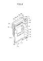
- a protection cover 61 is formed integrally with the board holder 51 at the lower side of the board holder 51 as shown in Fig. 8 .
- the protection cover 61 is provided so as to cover a lower area below the electrolytic capacitors 56 mounted on the first board 41 and protrude from the board holder 51 to the machine chamber R2 side. According to this construction, the lower side of the electrolytic capacitors 5 6 can be protected by the protection cover 61. Therefore, when the first board 41 is downwardly slid between the guide rails 43 and secured integrally with the board holder 51, the electrolytic capacitors 56 can be prevented from impinging against a peripheral part and thus being damaged.
- the partition plate 16 for partitioning the inside of the unit case (housing) 11 into the heat-exchange chamber R1 and the machine chamber R2 is provided to erect on the bottom plate 12 of the unit case 11
- the partition plate 16 is provided with the support member 50 which is joined to the upper surface portion 16A of the partition plate main body portion 16B and supports the electrical component mount unit 40 disposed in the machine chamber R2 .
- the support member 50 has the recess portion 54A with which the pipe plate 35 of the heat exchanger 21 disposed in the heat-exchange chamber R1 is engaged, and the support member 50 with which the electrical component mount unit 40 is integrated is mounted on the upper surface portion 16A of the partition plate main body portion 16B when the partition plate 16 is assembled, and the pipe plate 35 of the heat exchanger 21 is engaged with the recess portion 54A of the support member 50, whereby the support member 50 can be temporarily supported on the upper surface portion 16A of the partition plate main body portion 16B.
- the recess portion 54A of the support member 50 for supporting the electrical component amount unit 40 is engaged with the pipe plate 35 of the heat exchanger 21, whereby the support member 50 can be temporarily supported on the upper surface portion 16A of the partition plate main body portion 16D. Therefore, the electrical component mount unit 40 can be stably supported even under the state that the outer plate 15 is not secured to the unit case 11 in the middle of the assembling process of the outdoor unit 10, so that the assembling workability of the outdoor unit 10 is enhanced.
- the rib (projecting portion) 35A which is engaged with the recess portion 54A is provided to the pipe plate 35 of the heat exchanger 21. Therefore, when the partition plate 16 is assembled, the support member 50 for supporting the electrical component mount unit 40 is mounted on the upper surface portion 16A of the partition plate main body portion 16B, and the rib 35A is engaged with the recess portion 54A, whereby the support member 50 can be temporarily secured to the pipe plate 35 of the heat exchanger 21. Therefore, even under the state that the outer plate 15 is not secured to the unit case 11 in the middle of the assembling process of the outdoor unit 10, the electrical component mount unit 40 can be stably supported, and the assembling workability of the outdoor unit 10 can be enhanced.
- the support member 50 has the plate-like member 54 which extends to the partition plate main body portion 16B and protrudes to the back surface side of the unit case 11 over the height direction of the support member 50, the recess portion 54A is formed by bending the plate-like member 54 in a substantially L-shape toward the machine chamber R2 side along the back surface portion 16D of the partition plate 16, and the rib 35A is formed by bending the housing-inside edge portion of the pipe plate 35 in a substantially L-shape to the heat-exchange chamber R1 side.
- the support member 50 is temporarily jointed to the pipe plate 35 under the state that the back surface side edge portion 54B of the plate-like member 54 which forms the recess portion 54A is hooked to the rib 35A. Therefore, even under the state that the outer plate 15 is not secured to the unit case 11 in the middle of the assembling process of the outdoor unit 10, the electrical component mount unit 40 can be stably supported, and the assembling workability of the outdoor unit 10 can be enhanced.
- the rib 35A is engaged with the recess portion 54A, and the front surface 54C of the back surface side edge portion 54B of the plate-like member 54 and the back surface 35B of the rib 35 are brought into contact with each other and fixed to each other by screws. Therefore, even under the state that the outer plate 15 is not secured to the unit case 11 in the middle of the assembling process of the outdoor unit 10, the support member 50 with which the electrical component mount unit 40 is integrated can be temporarily and stably supported on the upper surface portion 16A of the partition plate main body portion 16B, so that the assembling workability of the outdoor unit 10 can be enhanced. Furthermore, the back surface side edge portion 54B of the plate-like member 54 and the rib 35A can be simply fixed to each other by screws while the front surface 54C of the back surface side edge portion 54B is brought into contact with the back surface 35B of the rib 54.
- the electrical component mount unit 40 has the first board 41 disposed just above the partition plate 16 so as to be substantially horizontal (in parallel) to the partition plate main body portion 16B, the second board 42 disposed in a substantially T-shape together with the first board 41, and the board holder 51 which is freely detachably mounted on the support member integrally with the first board 41 and the heat sink 55 for radiating heat generated from the electrical components mounted on the first board 41. Accordingly, the board holder 51 can be secured to the support member 50 after the support member 50 is temporarily supported on the upper surface portion 16A of the partition plate main body portion 16B.
- the center of gravity of the support member 50 is shifted to the left side, and the weight of the support member 50 is supported by the pipe plate 35 by hooking the tip of the plate-like member 54, thereby performing the assembling work. Accordingly, the assembling workability can be enhanced. Furthermore, the board holder 51 can be upwardly pulled out from the guide rails 43. Therefore, the first board 41 can be detached without dismounting the electrical component mount unit 40 from the unit case 11, and the maintenance performance of the first board 41 can be enhanced.
- the support member 50 supports the board holder 51 so that the heat sink 55 faces the heat-exchange chamber R1 through the opening portion 5 through which the heat-exchange chamber R1 and the machine chamber R2 intercommunicate with each other, and the first board 41 is disposed in the machine chamber R2. Therefore, the heat sink 55 can be cooled by air flowing in the heat-exchange chamber R1, and the heat occurring from the electrical components mounted on the first board 41 can be efficiently radiated.
- the outdoor unit 10 of the air conditioner in which the vertically extending partition plate 16 is provide so as to partition the inside of the unit case (housing) 11 into the heat-exchange chamber R1 and the machine chamber R2, the heat exchanger 21 and the air blowers 22 are mounted in the heat-exchange chamber R1 and the compressor 31 and the electrical components mount unit 40 are mounted in the machine chamber R2, the support member 50 is secured to the upper surface portion (upper end portion) 16A of the partition plate main body (partition plate main body portion) 16B, and the support member 50 has a pair of guide rails 43 facing the opening portion 5 which extends to both the end portions in the width direction of the partition plate 16, that is, the front surface portion 16C and the back surface portion 16D and through which the heat-exchange chamber R1 and the machine chamber R2 intercommunicate with each other.
- the electrical component mount unit 40 is further provided with the board holder 51 to which the first board (board) 41 is secured and whose side edge portions 51A are slideably engaged with the guide rails 43 so that the board holder 51 can be upwardly pulled out of the support member 50 integrally with the first board 41. Accordingly, under the maintenance work of the first board 41 such as exchange of the first board 41, exchange of electrical component parts mounted on the first board 41 or the like, the first board 41 can be easily upwardly pulled out and detached from the unit case 11 integrally with the board holder 51 whose side edge portions 51 are slidably engaged with the guide rails 43 without dismounting the overall electrical component mount unit 40 from the unit case 11. Therefore, the maintenance performance of the first board 41 can be enhanced.
- the guide rails 43 are designed to be substantially U-shaped in section and face each other, and the side edge portions 51A of the board holder 51 are inserted and engagedly fitted to the inner recess portions of the guide rails 43, whereby the board holder 51 is held between the guide rails 43 of the support member 50 so that the first board 41 can be upwardly pulled out (slidable) from the unit case 11 together with the board holder 51 without detaching the overall electrical component mount unit 40 from the unit case 11.
- the guide rails 43 serve as guides, and the first board 41 can be secured to the support member 50 without any risk that the first board 41 impinges against the surrounding parts and thus is damaged. Therefore, the workability can be enhanced.
- the board holder 51 is attached/detached to/from the support member 50 while the top panel 13 forming the top face of the unit case 11 is detached under the maintenance work of the first board 41. Therefore, the first board 41 can be easily detached integrally with the board holder 51 from the upper opening of the unit case 11 from which the top panel 13 is detached, and the maintenance performance can be enhanced.
- the first board 41 can be easily exchanged as occasion demands, and thus the maintenance performance of the electrical component mount unit 40 can be enhanced.
- the electrical component mount unit 40 has the second board 42, the second board 42 and the first board 41 are arranged substantially in a T-shape and secured to the support member 50, and the electrolytic capacitors 56 mounted on the first board 41 are arranged side by side in the vertical direction at the back surface side of the second board 42. Therefore, when the board holder 51 is secured to the support member 50 by sliding the board holder 51 between the guide rails 43 from the upper side while the side edge portions 51A thereof are fitted to the guide rails 43, the guide rails 43 serve as guides for guiding the board holder 43 to the support member 50 without any risk that the electrolytic capacitors 56 provided so as to protrude from the first board 41 to the machine chamber R2 side impinge against the second board 42 to be damaged. since the electrolytic capacitors 56 are arranged so as not to impinge against the second board 42 when the first board 41 is secured to the support member 50, the mounting/dismounting workability of the first board 41 can be enhanced.
- the support member 50 has the third support plate 48 which surrounds the electrolytic capacitors 56 and supports the second board 42, and thus the rigidity of the support member 50 for supporting the first board 41 and the second board 42 substantially in a T-shape can be enhanced by providing the third support plate 48.
- the third support plate 48 is provided to surround the electrolytic capacitors 56 which are provided to protrude from the first board 41 to the machine chamber R2 side. Therefore, the first board 41 is secured so that the electrolytic capacitors 56 are mounted in the space R3 between the third support plate 48 and the second board 42, whereby the electrolytic capacitors 56 can be prevented from impinging against the surrounding parts and thus being damaged, so that the workability can be enhanced.
Landscapes
- Engineering & Computer Science (AREA)
- Chemical & Material Sciences (AREA)
- Combustion & Propulsion (AREA)
- Mechanical Engineering (AREA)
- General Engineering & Computer Science (AREA)
- Other Air-Conditioning Systems (AREA)
Abstract
Description
- The present invention relates to an outdoor unit for an air conditioner.
- There is generally known an outdoor unit for an air conditioner in which the inside of a housing is partitioned into a heat exchange chamber and a machine chamber through a partition plate so that a heat exchanger and an air blower are mounted in the heat exchange chamber while a compressor and an electric component mount unit are mounted in the machine chamber. In this type of outdoor unit, the electric equipment mount unit is fixed to an outer plate of the housing by screws or the like, and disposed in an upper space of the machine chamber, and a heat sink for radiating heat generated from electrical components mounted in the electric equipment mount unit is disposed so as to protrude to the heat-exchange chamber side so that the heat sink is cooled by air flowing in the heat exchange chamber (see
JP-A-2001-201110 - The outer plate of the housing to which the electric equipment mountunit is to be fixed is secured to the housing after an operation test for the outdoor unit is finished, that is, at the last step of a fabrication process. Accordingly, the outer plate is not secured to the housing in the middle of the fabrication process, and the electric equipment mount unit is unstably supported on the upper portion of the partition plate, for example. Therefore, it is necessary to support the electric equipment mount unit by using a rod-shaped member (prop) or the like during the fabrication work of the outdoor unit, and thus workability is low.
- The electric equipment mount unit has a board on which various kinds of electrical components are mounted. In a maintenance work such as exchange of a hybrid IC board or the like, it is necessary to take out the electric equipment mount unit from the main body of an air conditioner, and thus the maintenance performance is degraded. In order to enhance the maintenance performance, it is considered that the electric equipment mount unit is provide with the board so that the board is freely attachable to and detachable from the electric equipment mount unit without dismounting the electric equipment mount unit from the main body of the air conditioner. However, with respect to outdoor units which are being promoted to be miniaturized, a working space in the housing is restricted, and thus it is difficult to attach or detach a board without damaging electrical components such as an electrolytic capacitors, etc. mounted on the board.
- The present invention has been implemented in view of the foregoing situation, and has an object to provide an outdoor unit of an air conditioner that can enhance assembling workability and maintenance performance of an electrical component mount board provided to an electric component mount unit.
- In order to attain the above object, according to a first aspect of the present invention, an outdoor unit (10) for an air conditioner having a housing (11), a partition plate (16) erected from a bottom plate (12) of the housing (11) to partition the inside of the housing into a heat-exchange chamber (R1) and a machine chamber (R2), a heat exchanger (21) that is disposed in the heat-exchange chamber (R1) and has a pipe plate (35), and an electrical component mount unit (40) in which electrical components are mounted, is characterized by further comprising a support member (50) that is configured to be mounted on an upper end face (16A) of a partition plate main body (16B) of the partition plate, wherein the support member (50) has a recess portion (54A) with which the pipe plate of the heat exchanger is engaged to temporarily hold the support member on the upper end face of the partition plate main body of the partition plate when the partition plate is assembled.
- In the above outdoor unit, the pipe plate of the heat exchanger has a projecting portion (35A) which is engaged with the recess portion (54)).
- In the above outdoor unit, the support member has a plate-like member (54) that extends to the partition plate main body and protrudes to the back surface side of the housing in a height direction, the recess portion (54A) is formed by bending the plate-like member along the back surface of the partition plate main body to the machine chamber side substantially in a T-shape, and the projecting portion (35A) is formed by bending an inner edge portion of the pipe plate in the housing to the heat-exchange chamber side substantially in a T-shape.
- In the above outdoor unit, the projecting portion and the recess portion are engaged with each other, and the front surface of the edge portion of the plate-like member and the back surface of the projection portion are brought into contact with each other and fixed to each other by screws.
- In the above outdoor unit according to any one of claims 1 to 4, wherein the electrical component mount unit has a first board (41) mounted just above the partition plate and arranged substantially horizontally to the partition plate main body, a second board (42) disposed to be substantially perpendicular to the first board, a heat sink (55) for radiating heat generated from the first board and electrical components mounted on the first board, and a board holder (51) for supporting the first board and the heat sink on the support member so that the first board and the heat sink are freely detachable from the support member integrally with each other.
- In the above outdoor unit, the support member has an
opening portion 5 through which the heat-exchange chamber and the machine chamber intercommunicates with each other, and supports the board holder so that the heat sink faces the heat-exchange chamber through theopening portion 5 and the first board is disposed in the machine chamber. - According to a second aspect of the present invention, an outdoor unit (10) for an air conditioner having a housing (11), a vertically extending partition plate (16) for partitioning the inside of the housing into a heat-exchange chamber (R1) and machine chamber (R2) a heat exchanger (21) disposed in the heat-exchange chamber (R1), and an electrical component mount unit (40) having electrical components disposed in the machine chamber, is characterized by further comprising a support member (50) that is configured to be secured to an upper end portion (16A) of a partition plate main body (16B) of the partition plate to support the electrical component mount unit, wherein the support member has a pair of guide rails (43) facing an opening portion (5) which extends to both the end portions (16C, 16D) in the width direction of the partition plate and through which the heat-exchange chamber and the machine chamber intercommunicate with each other, and the electrical component mount unit (40) has a board holder (51) to which a first board (41) having electrical components mounted thereon is secured, and both side edge portions (51A) of the board holder (51) are engageable with the guide rails so that the board holder is downwardly or upwardly slidable between the guide rails of the support member to attach or detach the board holder to or from the support member.
- In the above outdoor unit, the guide rails are configured to be substantially U-shaped in section and arranged to confront each other, and the side edge portions of the board holder are fitted in U-shaped recess portions of the guide rails to fix the board holder to the support member.
- In the above outdoor unit, under a maintenance work of the board the board holder is attached or detached to or from the support member under a state that a top panel forming a top surface of the housing is detached.
- In the above outdoor unit, the electrical components mounted on the first board are heat generating electrical components or consumable parts.
- In the above outdoor unit, the electrical component mount unit has a second board (42), and the first board and the second board are arranged in a substantially T-shape and secured to the support member, and the electrical components mounted on the first board contain electrolytic capacitors that are arranged side by side vertically at the back surface side of the second board.
- In the above outdoor unit, the support member further has a support plate (48) that surrounds the electrolytic capacitors and supports the second board.
- According to the present invention, when the partition plate is assembled, the recess portion of the support member for supporting the electrical component mount unit is engaged with the pipe plate of the heat exchanger to temporarily support the support member on the upper end surface of the partition plate main body. Therefore, even in the middle of the assembling process of the outdoor unit, that is, even under the state that the outer plate is not attached to the housing, the electrical component mount unit can be stably supported, and thus the assembling workability of the outdoor unit can be enhanced. Furthermore, under a maintenance work of the first board of the electrical component mount unit, the first board is upwardly pulled out along the guide rails, whereby the board holder can be simply detached from the electrical component mount unit, and thus the maintenance performance of the first board can be enhanced.
-
-
Fig. 1 is a perspective view showing the outlook of an outdoor unit according to an embodiment to which the present invention is applied; -
Fig. 2 is a perspective view showing the internal construction of the outdoor unit; -
Fig. 3 is a perspective view showing the internal construction of the outdoor unit under the state that an electric equipment mount unit is detached; -
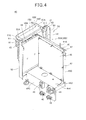
Fig. 4 is a perspective view showing the electric equipment mount unit; -
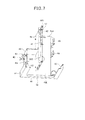
Fig. 5 is a plan view showing a temporary support structure of the electric equipment mount unit; -
Fig. 6 is a perspective view showing a support member; -
Fig. 7 is a plan view showing the support member; and -
Fig. 8 is a perspective view showing a board holder. - A preferred embodiment according to the present invention will be described hereunder with reference to the accompanying drawings.
An air conditioner according to this embodiment comprises anoutdoor unit 10 and an indoor unit (not shown), and performs cooling operation and heating operation by making refrigerant flow through a refrigerant circuit which is constructed by connecting theoutdoor unit 10 and the indoor unit trough a refrigerant pipe. Theoutdoor unit 10 is disposed outdoors. In the outdoor unit, refrigerant is heat-exchanged with outdoor air so that it is condensed while radiating heat to the outside air under cooling operation, and also vaporized with absorbing heat from the outside air during heating operation. Here, the up-and-down direction and the right-and-left direction described below are defined as directions when theoutdoor unit 10 is viewed from the front side thereof under the state that theoutdoor unit 10 is installed. -
Fig. 1 is a perspective view showing theoutdoor unit 10. Theoutdoor unit 10 has a substantially rectangular parallelepiped box-shaped unit case (housing) 11, and theunit case 11 has abottom plate 12, atop panel 13, afront panel 14 and anouter plate 15. The inside of theunit case 11 is vertically partitioned into a heat-exchange chamber R1 and a machine chamber R2 by apartition plate 16 erected from thebottom plate 12 so that the heat-exchange chamber R1 and the machine chamber R2 are arranged side by side horizontally. Thefront panel 14 is bisected into afirst front panel 14A and asecond front panel 14B at right and left sides with thepartition plate 16 located at the boundary therebetween. A worker can perform a maintenance work for parts in the heat-exchange chamber R1 from the front side of theoutdoor unit 10 by detaching thefirst front panel 14A, and also can perform a maintenance work for parts in the machine chamber R2 from the front side of theoutdoor unit 10 by detaching thesecond front panel 14B. - Two air blow-out
ports 28 for blowing out air heat-exchanged in the heat-exchange chamber R1 are formed in thefirst front panel 14A at the heat-exchange chamber R1 side so as to be aligned with each other in the up-and-down direction. The air blow-outports 28 are covered by mesh-shaped fan guards 29. As not shown, the air blow-outports 28 are covered by rounded flange type fan covers, andair blowers 22 described later are provided in opening portions of the fan covers. -
Fig. 2 is a perspective view showing theoutdoor unit 10 under the state that thetop panel 13, thefront panel 14 and theouter plate 15 are detached from theoutdoor unit 10. The inside of theunit case 11 is partitioned into the heat-exchange chamber R1 and the machine chamber R2 by thepartition plate 16 erected from thebottom plate 12. As shown inFig. 2 , aheat exchanger 21 is mounted at the back surface side in the heat-exchange chamber R1, andair blowers 22 are mounted at the front surface side in the heat-exchange chamber R1 so as to be arranged side by side in the up-and-down direction. Theheat exchanger 21 is formed to be bent in a substantially L-shape in top view, and disposed so as to extend from the left side surface (outer surface) of the heat-exchange chamber R1 to the back surface thereof along these surfaces. As described above, theheat exchanger 21 forms the left side surface and the back surface of the heat-exchange chamber R1 (that is, the unit case 11), and the overall exposure surface from the left side surface to the back surface of theheat exchanger 21 functions as an air flowing passage (air suction port) . As not shown, the surface of the heat exchanger is covered by a fin guard formed of a resin net or the like so that a human body or the like is prevented from coming into contact with theheat exchanger 21. - The
air blowers 22 are secured to a pair of right andleft support posts support posts heat exchanger 21, and the lower end portions of thesupport posts bottom plate 12 by screws.
Each of theair blowers 22 comprises afan motor 26 fixed to the upper portion of thesupport post 24L (24R) through apedestal 25, and a propeller fan (axial fan) 27 secured to the shaft of thefan motor 26, and thepropeller fans 27 are disposed adjacently to the front surface side of the heat-exchange chamber R1. When thepropeller fans 27 are rotated by thefan motors 26, outdoor air is sucked from the surrounding of theoutdoor unit 10, more specifically, from the back surface side and the left side surface side of theheat exchanger 21 into the heat-exchange chamber R1. The sucked outdoor air is heat-exchanged with refrigerant flowing in theheat exchanger 21, passed through the air blow-outports 28 provided in the front surface of the heat-exchange chamber R1 and discharged to the outside of theoutdoor unit 10. That is, theoutdoor unit 10 is configured as a front-side blow-out type outdoor unit for blowing out heat-exchanged air from the front side thereof. - Refrigerant circuit constituent parts such as a
compressor 31, an accumulator (not shown), areceiver thank 33, an oil separator (not shown), valves such as four-way valve 32, an expansion valve (not shown), etc. which constituent parts of the refrigerant circuit are connected to one another through pipes, and mounted in a substantially lower space of the machine chamber R2. - Furthermore, a service valve for a gas pipe and a service valve for a liquid pipe are fixed adjacently to each other at the front surface side of the machine chamber R2 and at the upper right side of the
compressor 31. A gas pipe and a liquid pipe (not shown) of a unit pipe extending from the indoor unit are connected to the service valve for the gas pipe and the service valve for the liquid pipe respectively, thereby constructing a refrigerant circuit in which refrigerant is circulated. Furthermore, an electricalcomponent mount unit 40 in which various kinds of electrical components such as a control board for controlling the air conditioner, etc. are mounted is disposed at an upper space of the machine chamber R2 . The electricalcomponent mount unit 40 has asupport member 50, and afirst board 41, asecond board 42 and aheat sink 55 which are integrally supported by thesupport member 50. Thesupport member 50 is provided with the electricalcomponent mount unit 40, and it is disposed in the upper space of the machine chamber R2 so that theheat sink 55 faces and protrudes into the heat-exchange chamber R1. Thesupport member 50 extends in the width direction of thepartition plate 16, that is, in the front-and-rear direction of theunit case 11. - As shown in
Fig. 3 , thepartition plate 16 comprises a partition plate main body portion (partition plate main body) 16B which is disposed between the heat-exchange chamber R1 and the machine chamber R2 and through which the heat-exchange chamber R1 and the machine chamber R2 are separated from each other, a front surface portion (endportion) 16C formed by bending (folding) the side edge portion of the front surface side of the partition platemain body portion 16B to the machine chamber R2 side, a back surface portion (end portion) formed by bending the side edge portion of the back surface side of the partition platemain body portion 16B to the machine chamber R2 side substantially in parallel to thefront surface portion 16C, and an upper surface portion (upper end face) 16A formed by bending the upper edge portion of the partition platemain body portion 16B to the machine chamber R2 side. Thepartition plate 16 is formed by bending a thin sheet metal as described above to enhance the rigidity (strength) of thepartition plate 16. - The
partition plate 16 is erected from thebottom plate 12, and theback surface portion 16D thereof is fixed to theheat exchanger 21 by screws. Specifically, theheat exchanger 21 has apipe plate 35 at a right side end portion thereof, and thepipe plate 35 has a rib (projecting portion) 35A formed by bending an inner side edge portion of theunit case 11 in a substantially L-shape to the heat-exchange chamber R1 side. Theback surface portion 16D of thepartition plate 16 is fixed to therib 35A by screws. Anopening portion 5 is provided at the upper side of thepartition plate 16 so as to intercommunicate the heat-exchange chamber R1 and the machine chamber R2. - As shown in
Fig. 2 , the electricalcomponent mount unit 40 is mounted on theupper surface portion 16A of thepartition plate 16 so as to block theopening portion 5, and thesupport member 50 is joined to thepartition plate 16.
The electricalcomponent mount unit 40 has thesupport member 50, and thefirst board 41, thesecond board 42 and theheat sink 55 which are integrally supported by thesupport member 50. Thefirst board 41 and thesecond board 42 are arranged in a substantially T-shape so that thesecond board 42 is provided substantially perpendicularly to thefirst board 41 disposed in the front-and-rear direction of theoutdoor unit 10. Thefirst board 41 and theheat sink 55 are integrally fixed to each other through aboard holder 51. Theboard holder 51 is freely detachably supported on thesupport member 50 so that theheat sink 55 faces the heat-exchange chamber R1 side through theopening portion 5. - As shown in
Figs. 2 and4 , thesupport member 50 faces theopening portion 5 through which the heat-exchange chamber R1 and the machine chamber R2 intercommunicate with each other, and has a pair ofguide rails 43 provided just above thepartition plate 16. The guide rails 43 are configured to be substantially U-shaped in cross-section and arranged to face each other. Oneguide rail 43 extends to thefront surface portion 16C of thepartition plate 16, and theother guide rail 43 extends to a neighborhood of theback surface portion 16D.
Theboard holder 51 is secured (held) between the guide rails 43. Both theside edge portions 51A of theboard holder 51 are respectively egageable with the guide rails 43 so that theboard holder 51 can be upwardly and downwardly pulled (slidable) along the guide rails 43 integrally with thefirst board 41 and theheat sink 55, thereby detaching or attaching theboarder holder 51 from or to thesupport member 50. Theboard holder 51 is a resin molded article, and designed in a frame-like shape to have aholder opening portion 51B substantially at the center thereof. - Electrical components having high heat release values such as a hybrid IC (HIC) 57, etc. are mounted on the
first board 41, and thefirst board 41 is fixed to theboard holder 51 by screws or the like so that the electrical components having high heat release values face and block theholder opening portion 51B. These electrical components having high heat release values mounted on the first aboard 41 are thermally connected to theheat sink 55.
Theheat sink 55 is configured so that plural metal plate members constituting fins are arranged to be spaced from one another vertically. Theheat sink 55 is fixed to theboard holder 51 by screws or the like, and the plural fins are provided to protrude to the heat-exchange chamber R1 side through theopening portion 5 through which the heat-exchange chamber R1 and the machine chamber R2 intercommunicate with each other.
According to this construction, heat generated from the electrical components mounted on thefirst board 41 is radiated to theheat sink 55, and further theheat sink 55 is cooled by air flowing in the heat-exchange chamber R1, so that the heat emitted from the electrical components mounted on thefirst board 41 can be efficiently radiated. - A
hood 59 is fixed to theboard holder 51 at the upper side of theheat sink 55 so as to cover most of the overall projection area of theheat sink 55. Thehood 59 is designed in such a substantially box-like shape so that the top surface thereof is opened and a side surface thereof at the machine chamber R2 side is cut out wholly in the front-and-rear direction. Thehood 59 is disposed so that the upper end surfaces 59B of the other three side surfaces of thehood 59 come into contact with the lower surface of thetop panel 13 of theunit case 11. According to this construction, water such as rain water or the like intruding from the back surface side of theheat exchanger 21 into the heat-exchange chamber R1 can be prevented from intruding from the upper side of theheat sink 55 into the machine chamber R2 side by thehood 59. - A
bottom surface 59C of thehood 59 is cut out along theside surface 59A at the heat-exchange chamber R1 side to form a cut-outportion 59D through which the upper space of thehood 59 and the heat-exchange chamber R1 intercommunicate with each other. Air in the machine chamber R2 flows through the cut-outportion 59D into the heat-exchange chamber R1 while attracted by air flowing in the heat-exchange chamber R1. Therefore, air which is heated by heat generated from the electrical components provided to the electricalcomponent mount unit 40 can be circulated without staying in the machine chamber R2. According to this construction, water such as rain water or the like invading from the back surface side of theheat exchanger 21 into the heat-exchange chamber R1 can be prevented from intruding from the upper portion of theheat sink 55 into the machine chamber R2 side, and thus it is unnecessary to cover the whole electricalcomponent mount unit 40 by a case or the like. Therefore, the number of parts of the electricalcomponent mount unit 40 can be reduced, and also thefirst board 41 of the electricalcomponent mount unit 40 can be mounted or dismounted by merely detaching any panel (plate) of theunit case 11, so that workability for maintenance can be enhanced. - As shown in
Figs. 4 and5 , thesupport member 50 has asecond support plate 45 for supporting thesecond board 42 substantially particularly to thefirst board 41. Thesecond support board 45 comprises a secondboard securing portion 45A which is provided so as to extend substantially in parallel to the extension direction (i.e., the vertical direction) of the guide rails 43, and abase portion 45B which is configured to be substantially L-shape in section so as to extend horizontally from the lower portion of the second board securingport ion 45A and further extend vertically downwardly. Thesecond board 42 is fixed to the secondboard securing portion 45A by fastening pieces such asscrews 47 or the like. As not shown, thesecond board 42 may be fixed to the secondboard securing portion 45A by clamping pieces such as clips or the like in addition to the screw-based fixing. - The
base portion 45B is provided to be continuous with the lower end of the secondboard securing portion 45A so that the horizontally extendingpart thereof protrudes to the front surface side of the machine chamber R2. Thebase portion 45B further has a terminal table 45C which extends vertically downwardly from the horizontally extending part and has plural electricalpart connection portions 46 to which power source terminals and connectors are connected so that the terminal table 45C hands downwardly to the lower side of the electricalcomponent mount unit 40. Furthermore, a fixingportion 45D for fixing thesupport member 50 to theouter plate 15 of theunit case 11 is formed at the right edges of the secondboard securing portion 45A and thebase portion 45B. As not shown, the fixingportion 45D is formed so as to extend to the confronting faces of theouter plate 15 and the secondfront surface panel 14B, and fixed through screws to a side edge portion of theouter plate 15 which is formed by bending the edge of theouter plate 15 to the inside of theunit case 11. In this embodiment, the secondboard securing portion 45A, thebase portion 45B, the terminal table 45C and the fixingportion 45D are integrally formed by subjecting one metal plate to sheet metal processing such as bending processing or the like. However, these portions may be separately formed, assembled with one another and fixed to one another by screws or the like. - The
board holder 51 is provided with ahook member 58 at the upper side of thefirst board 41. Thehook member 58 is formed of metal such as aluminum or the like, and provided with ahook pawl 58A which is formed integrally with thehook member 58 by bending the tip of thehook member 58 downwardly. Ahook groove 58B is formed on the upper end surface of thesecond support plate 45. When theboard holder 51 is secured to thesupport member 50, thehook pawl 58A is fixedly fitted in thehook groove 58B as shown inFig. 4 . Accordingly, thefirst board 41 and thesecond board 42 can be joined to each other while arranged in a substantially T-shape and thus they can be stably supported. - The
board holder 51 has twoscrew holes 51E which are provided in the neighborhood of the guide rails 43 at the upper portion of theboard holder 51. Theboard holder 51 is fixed to thesupport member 50 by screws inserted from the machine chamber R2 side through the screw holes 51E. That is, theboard holder 51 is fixedly mounted to thesupport member 50 at the tree points of thehook pawl 58A and the screw holes 51E. Furthermore, thehook paws 58A and the screw holes 51E for fixing theboard holder 51 to thesupport member 50 are provided at the upper portion of theboard holder 51. Therefore, theboard holder 51 can be easily detached from the upper opening of theoutdoor unit 10 from which thetop panel 13 is detached, and the maintenance performance for thefirst board 41 secured to theboard holder 51 can be enhanced. - Furthermore, the
support member 50 has a plate-like member 54 which extends to the partition platemain body portion 16B and is provided over the up-and-down direction of thesupport member 50 so as to protrude to the back surface side of thesupport member 50. The plate-like member 54 is fixed to the side surface at the heat-exchange chamber R1 side of theguide rail 43 located at the rear side of the unit case 11 (hereinafter referred to as "rear-side guide rail") by screws or the like, and bent substantially in an L-shape to the machine chamber R2 side along theback surface portion 16D of thepartition plate 16, whereby arecess portion 54A with which a rib (projecting portion) 35A formed in thepipe plate 35 of theheat exchanger 21 is engaged is formed between the plate-like member 54 and the rear-side guide rail 43 in thesupport member 50. - Next, an assembling process when the electrical
component mount unit 40 is secured to theunit case 11 will be described.
First, when thepartition plate 16 is assembled to theunit case 11, theheat exchanger 21 has been already fixed and erected from thebottom plate 12. Under this state, thepartition plate 16 is erected from thebottom plate 12, and theback surface portion 16D of thepartition plate 16 is fixed to therib 35A formed in thepipe plate 35 of theheat exchanger 21 by screws or the like. Subsequently, therib 35A is engaged with therecess portion 54A to mount thesupport member 50 on theupper surface portion 16A of the partition platemain body portion 16B before thesupport member 50 with which the electricalcomponent mount unit 40 is integrated is secured to theboard holder 51. Under this state, theboard holder 51 is not secured to thesupport member 50, and thus the weight balance of thesupport member 50 is deviated to the right side due to the weight of thesecond board 42. Therefore, thesupport member 50 is temporarily supported on theupper surface portion 16A of thepartition plate 16 under the state that the back surface side edge portion (tip) 54B of the plate-like member 54 is hooked to therib 35A. - Under this state, the
front surface 54C of the back surfaceside edge portion 54B of the plate-like member 54 is brought into contact with theback surface 35B of therib 35A and the back surfaceside edge portion 54B is fixed to therib 35A at two places in the up-and-down direction by screws as shown inFig. 5 . Thereafter, thefirst board 41 and theheat sink 55 are secured just above thepartition plate 16 integrally with theboard holder 51 so that thefirst board 41 is disposed substantially in parallel to each other (horizontal to each other). According to this construction, thesupport member 50 can be stably supported on theupper surface portion 16A of thepartition plate 16 even in the middle of the assembling process of theoutdoor unit 10, that is, even when theouter plate 15 is not attached to theunit case 11. In the final step of the assembling process of theoutdoor unit 10, the fixingportion 45D of thesupport member 50 with which the electricalcomponent mount unit 40 is integrated is fixed to theouter plate 15 by screws or the like after theouter plate 15 is secured to theunit case 11. - As shown in
Fig. 6 , thesupport member 50 has afirst support plate 44 which blocks the lower area of theopening portion 5 and through which the guide rails 43 are connected. The guide rails 43 and thefirst support plate 44 are formed by subjecting one metal plate to sheet-metal processing such as a bending work or the like. Furthermore, afirst pedestal portion 52 having an upper surface on which theboard holder 51 for holding thefirst board 41 is mounted, and a second pedestal portion 53 are formed integrally with thefirst support plate 44. -
Fig. 7 is a plan view showing thesupport member 50 when thesupport member 50 is viewed in the direction of an arrow inFig. 6 . As shown inFig. 7 , thesupport member 50 has a third support plate (support plate) 48 having a substantially L-shaped cross-section through which thefirst support plate 44 and thesecond support plate 45 are connected to each other. Thethird support plate 48 is connected to the back surface side of thesecond support plate 45 at one side thereof, and also connected to theguide rail 43 at the back side of theoutdoor unit 10 at the other end thereof. A space R3 is formed between thesecond support plate 45 and thethird support plate 48 in thesupport plate 50. Thefirst support plate 44 and thesecond support plate 45 are connected to each other through thethird support plate 48, and a leftward extendingextension portion 45E of thebase portion 45B is connected to thefirst support plate 44, whereby the rigidity of thesupport member 50 is enhanced.Plural clips 63 are provided to the back surface side of thethird support plate 48. Theclips 63 are used to collectively hold various kinds of cables wired in the electrical component mount unit 4. - As shown in
Fig. 8 , electrical components as consumable parts which are required to be exchanged such aselectrolytic capacitors 56, etc. are mounted on thefirst board 41. Theelectrolytic capacitors 56 are arranged vertically side by side in proximity to the back surface side of the machine chamber R2 so as to protrude from thefirst board 41 to the machine chamber R2 side. A cut-out 51D is formed at thelower end portion 51C of theboard holder 51, and thebase portion 45B is fitted in the cut-out 51D when theboard holder 51 is downwardly slid between the guide rails 43. According to this embodiment, theelectrolytic capacitors 56 are aligned with one another in the up-and-down direction as shown inFig. 8 , however, the present invention is not limited to this style. For example, the electrolytic capacitors may be disposed in a so-called staggering (zigzag) arrangement. - According to this construction, the
support member 50 supports thefirst board 41 and thesecond board 42 so that thefirst board 41 and thesecond board 42 are disposed in a substantially T-shaped arrangement, theelectrolytic capacitors 56 mounted on thefirst board 41 are arranged at the back surface side of thesecond board 42, and accommodated in the space R3 formed between thesecond support board 45 and thethird support plate 48. Theboard holder 51 through which thefirst board 41 and theheat sink 55 are fixed integrally with each other can be mounted by downwardly sliding theboarder holder 51 between the guide rails 43 and also dismounted by upwardly pulling out theboarder holder 51. Therefore, theboard holder 51 is slid along the guide rails 43, whereby theboard holder 51 can be mounted or dismounted from the upper opening of theoutdoor unit 10 from which thetop panel 13 is detached. Furthermore, when theboard holder 51 is mounted or dismounted, the guide rails 43 serve as guides, and the electrical components such as theelectrolytic capacitors 56, etc. secured to thefirst board 41 can be mounted or dismounted without pay ing at tent ion to a risk that the electrical components impinge against a surrounding part such as thesecond board 42 or the like and thus damaged, so that the mounting/dismounting workability of thefirst board 41 can be enhanced. - A
protection cover 61 is formed integrally with theboard holder 51 at the lower side of theboard holder 51 as shown inFig. 8 . Theprotection cover 61 is provided so as to cover a lower area below theelectrolytic capacitors 56 mounted on thefirst board 41 and protrude from theboard holder 51 to the machine chamber R2 side. According to this construction, the lower side of theelectrolytic capacitors 5 6 can be protected by theprotection cover 61. Therefore, when thefirst board 41 is downwardly slid between the guide rails 43 and secured integrally with theboard holder 51, theelectrolytic capacitors 56 can be prevented from impinging against a peripheral part and thus being damaged. - As described above, according to the embodiment to which the present invention is applied, in the
outdoor unit 10 of the air conditioner in which thepartition plate 16 for partitioning the inside of the unit case (housing) 11 into the heat-exchange chamber R1 and the machine chamber R2 is provided to erect on thebottom plate 12 of theunit case 11, thepartition plate 16 is provided with thesupport member 50 which is joined to theupper surface portion 16A of the partition platemain body portion 16B and supports the electricalcomponent mount unit 40 disposed in the machine chamber R2 . Thesupport member 50 has therecess portion 54A with which thepipe plate 35 of theheat exchanger 21 disposed in the heat-exchange chamber R1 is engaged, and thesupport member 50 with which the electricalcomponent mount unit 40 is integrated is mounted on theupper surface portion 16A of the partition platemain body portion 16B when thepartition plate 16 is assembled, and thepipe plate 35 of theheat exchanger 21 is engaged with therecess portion 54A of thesupport member 50, whereby thesupport member 50 can be temporarily supported on theupper surface portion 16A of the partition platemain body portion 16B.
Accordingly, when thepartition plate 16 is assembled, therecess portion 54A of thesupport member 50 for supporting the electricalcomponent amount unit 40 is engaged with thepipe plate 35 of theheat exchanger 21, whereby thesupport member 50 can be temporarily supported on theupper surface portion 16A of the partition platemain body portion 16D. Therefore, the electricalcomponent mount unit 40 can be stably supported even under the state that theouter plate 15 is not secured to theunit case 11 in the middle of the assembling process of theoutdoor unit 10, so that the assembling workability of theoutdoor unit 10 is enhanced. - Furthermore, according to the embodiment of the present invention, the rib (projecting portion) 35A which is engaged with the
recess portion 54A is provided to thepipe plate 35 of theheat exchanger 21. Therefore, when thepartition plate 16 is assembled, thesupport member 50 for supporting the electricalcomponent mount unit 40 is mounted on theupper surface portion 16A of the partition platemain body portion 16B, and therib 35A is engaged with therecess portion 54A, whereby thesupport member 50 can be temporarily secured to thepipe plate 35 of theheat exchanger 21. Therefore, even under the state that theouter plate 15 is not secured to theunit case 11 in the middle of the assembling process of theoutdoor unit 10, the electricalcomponent mount unit 40 can be stably supported, and the assembling workability of theoutdoor unit 10 can be enhanced. - Still furthermore, according to the embodiment of the present invention, the
support member 50 has the plate-like member 54 which extends to the partition platemain body portion 16B and protrudes to the back surface side of theunit case 11 over the height direction of thesupport member 50, therecess portion 54A is formed by bending the plate-like member 54 in a substantially L-shape toward the machine chamber R2 side along theback surface portion 16D of thepartition plate 16, and therib 35A is formed by bending the housing-inside edge portion of thepipe plate 35 in a substantially L-shape to the heat-exchange chamber R1 side. Therefore, by engaging therib 35A with therecess portion 54A, thesupport member 50 is temporarily jointed to thepipe plate 35 under the state that the back surfaceside edge portion 54B of the plate-like member 54 which forms therecess portion 54A is hooked to therib 35A. Therefore, even under the state that theouter plate 15 is not secured to theunit case 11 in the middle of the assembling process of theoutdoor unit 10, the electricalcomponent mount unit 40 can be stably supported, and the assembling workability of theoutdoor unit 10 can be enhanced. - Still furthermore, according to the embodiment of the present invention, the
rib 35A is engaged with therecess portion 54A, and thefront surface 54C of the back surfaceside edge portion 54B of the plate-like member 54 and theback surface 35B of therib 35 are brought into contact with each other and fixed to each other by screws. Therefore, even under the state that theouter plate 15 is not secured to theunit case 11 in the middle of the assembling process of theoutdoor unit 10, thesupport member 50 with which the electricalcomponent mount unit 40 is integrated can be temporarily and stably supported on theupper surface portion 16A of the partition platemain body portion 16B, so that the assembling workability of theoutdoor unit 10 can be enhanced. Furthermore, the back surfaceside edge portion 54B of the plate-like member 54 and therib 35A can be simply fixed to each other by screws while thefront surface 54C of the back surfaceside edge portion 54B is brought into contact with theback surface 35B of therib 54. - Still furthermore, according to the embodiment of the present invention, the electrical
component mount unit 40 has thefirst board 41 disposed just above thepartition plate 16 so as to be substantially horizontal (in parallel) to the partition platemain body portion 16B, thesecond board 42 disposed in a substantially T-shape together with thefirst board 41, and theboard holder 51 which is freely detachably mounted on the support member integrally with thefirst board 41 and theheat sink 55 for radiating heat generated from the electrical components mounted on thefirst board 41.
Accordingly, theboard holder 51 can be secured to thesupport member 50 after thesupport member 50 is temporarily supported on theupper surface portion 16A of the partition platemain body portion 16B. When thesupport member 50 is temporarily secured to thepipe plate 35, the center of gravity of thesupport member 50 is shifted to the left side, and the weight of thesupport member 50 is supported by thepipe plate 35 by hooking the tip of the plate-like member 54, thereby performing the assembling work. Accordingly, the assembling workability can be enhanced. Furthermore, theboard holder 51 can be upwardly pulled out from the guide rails 43. Therefore, thefirst board 41 can be detached without dismounting the electricalcomponent mount unit 40 from theunit case 11, and the maintenance performance of thefirst board 41 can be enhanced. - Still furthermore, according to the embodiment of the present invention, the
support member 50 supports theboard holder 51 so that theheat sink 55 faces the heat-exchange chamber R1 through theopening portion 5 through which the heat-exchange chamber R1 and the machine chamber R2 intercommunicate with each other, and thefirst board 41 is disposed in the machine chamber R2. Therefore, theheat sink 55 can be cooled by air flowing in the heat-exchange chamber R1, and the heat occurring from the electrical components mounted on thefirst board 41 can be efficiently radiated. - According to the
outdoor unit 10 of the air conditioner in which the vertically extendingpartition plate 16 is provide so as to partition the inside of the unit case (housing) 11 into the heat-exchange chamber R1 and the machine chamber R2, theheat exchanger 21 and theair blowers 22 are mounted in the heat-exchange chamber R1 and thecompressor 31 and the electrical components mountunit 40 are mounted in the machine chamber R2, thesupport member 50 is secured to the upper surface portion (upper end portion) 16A of the partition plate main body (partition plate main body portion) 16B, and thesupport member 50 has a pair ofguide rails 43 facing theopening portion 5 which extends to both the end portions in the width direction of thepartition plate 16, that is, thefront surface portion 16C and theback surface portion 16D and through which the heat-exchange chamber R1 and the machine chamber R2 intercommunicate with each other.
The electricalcomponent mount unit 40 is further provided with theboard holder 51 to which the first board (board) 41 is secured and whoseside edge portions 51A are slideably engaged with the guide rails 43 so that theboard holder 51 can be upwardly pulled out of thesupport member 50 integrally with thefirst board 41.
Accordingly, under the maintenance work of thefirst board 41 such as exchange of thefirst board 41, exchange of electrical component parts mounted on thefirst board 41 or the like, thefirst board 41 can be easily upwardly pulled out and detached from theunit case 11 integrally with theboard holder 51 whoseside edge portions 51 are slidably engaged with the guide rails 43 without dismounting the overall electricalcomponent mount unit 40 from theunit case 11. Therefore, the maintenance performance of thefirst board 41 can be enhanced. - According to the embodiment of the present invention, the guide rails 43 are designed to be substantially U-shaped in section and face each other, and the
side edge portions 51A of theboard holder 51 are inserted and engagedly fitted to the inner recess portions of the guide rails 43, whereby theboard holder 51 is held between the guide rails 43 of thesupport member 50 so that thefirst board 41 can be upwardly pulled out (slidable) from theunit case 11 together with theboard holder 51 without detaching the overall electricalcomponent mount unit 40 from theunit case 11. Accordingly, when thefirst board 41 is fixed to thesupport member 50 integrally with theboard holder 51, the guide rails 43 serve as guides, and thefirst board 41 can be secured to thesupport member 50 without any risk that thefirst board 41 impinges against the surrounding parts and thus is damaged. Therefore, the workability can be enhanced. - Furthermore, according to the embodiment of the present invention, the
board holder 51 is attached/detached to/from thesupport member 50 while thetop panel 13 forming the top face of theunit case 11 is detached under the maintenance work of thefirst board 41. Therefore, thefirst board 41 can be easily detached integrally with theboard holder 51 from the upper opening of theunit case 11 from which thetop panel 13 is detached, and the maintenance performance can be enhanced. - Still furthermore, according to the embodiment of the present invention, since electrical components having a large amount of heat generation such as hybrid IC, etc. or electrical components as consumable parts are mounted on the
first board 41, heat generated from the electrical components mounted on thefirst board 41 can be radiated through theheat sink 55 which is fixed to theboard holder 51 integrally with thefirst board 41. Furthermore, the electrical components having a large amount of heat generation such as the hybrid IC, etc. break down relatively frequently, and thus maintenance is required to these electrical components. Accordingly, if electrical components having a large amount of heat generation or electrical components as consumable parts are mounted on the easily detachablefirst board 41 and such afirst board 41 is prepared as an exchangeable part, thefirst board 41 can be easily exchanged as occasion demands, and thus the maintenance performance of the electricalcomponent mount unit 40 can be enhanced. - Furthermore, the electrical
component mount unit 40 has thesecond board 42, thesecond board 42 and thefirst board 41 are arranged substantially in a T-shape and secured to thesupport member 50, and theelectrolytic capacitors 56 mounted on thefirst board 41 are arranged side by side in the vertical direction at the back surface side of thesecond board 42. Therefore, when theboard holder 51 is secured to thesupport member 50 by sliding theboard holder 51 between the guide rails 43 from the upper side while theside edge portions 51A thereof are fitted to the guide rails 43, the guide rails 43 serve as guides for guiding theboard holder 43 to thesupport member 50 without any risk that theelectrolytic capacitors 56 provided so as to protrude from thefirst board 41 to the machine chamber R2 side impinge against thesecond board 42 to be damaged. since theelectrolytic capacitors 56 are arranged so as not to impinge against thesecond board 42 when thefirst board 41 is secured to thesupport member 50, the mounting/dismounting workability of thefirst board 41 can be enhanced. - The
support member 50 has thethird support plate 48 which surrounds theelectrolytic capacitors 56 and supports thesecond board 42, and thus the rigidity of thesupport member 50 for supporting thefirst board 41 and thesecond board 42 substantially in a T-shape can be enhanced by providing thethird support plate 48. Furthermore, thethird support plate 48 is provided to surround theelectrolytic capacitors 56 which are provided to protrude from thefirst board 41 to the machine chamber R2 side. Therefore, thefirst board 41 is secured so that theelectrolytic capacitors 56 are mounted in the space R3 between thethird support plate 48 and thesecond board 42, whereby theelectrolytic capacitors 56 can be prevented from impinging against the surrounding parts and thus being damaged, so that the workability can be enhanced.
Claims (12)
- An outdoor unit (10) for an air conditioner having a housing (11), a partition plate (16) erected from a bottom plate (12) of the housing (11) to partition the inside of the housing into a heat-exchange chamber (R1) and a machine chamber (R2), a heat exchanger (21) that is disposed in the heat-exchange chamber (R1) and has a pipe plate (35), and an electrical component mount unit (40) in which electrical components are mounted, characterized by further comprising a support member (50) that is configured to be mounted on an upper end face (16A) of a partition plate main body (16B) of the partition plate, wherein the support member (50) has a recess portion (54A) with which the pipe plate of the heat exchanger is engaged to temporarily hold the support member on the upper end face of the partition plate main body of the partition plate when the partition plate is assembled.
- The outdoor unit according to claim 1, wherein the pipe plate of the heat exchanger has a projecting portion (35A) which is engaged with the recess portion (54A).
- The outdoor unit according to claim 2, wherein the support member has a plate-like member (54) that extends to the partition plate main body and protrudes to the back surface side of the housing in a height direction, the recess portion (54A) is formed by bending the plate-like member along the back surface of the partition plate main body to the machine chamber side substantially inaT-shape, and the projecting portion (35A) is formed by bending an inner edge portion of the pipe plate in the housing to the heat-exchange chamber side substantially in a T-shape.
- The outdoor unit according to claim 3, wherein the projecting portion and the recess portion are engaged with each other, and the front surface of the edge portion of the plate-like member and the back surface of the projection portion are brought into contact with each other and fixed to each other by screws.
- The outdoor unit according to any one of claims 1 to 4, wherein the electrical component mount unit has a first board (41) mounted just above the partition plate and arranged substantially horizontally to the partition plate main body, a second board (42) disposed to be substantially perpendicular to the first board, a heat sink (55) for radiating heat generated from the first board and electrical components mounted on the first board, and a board holder (51) for supporting the first board and the heat sink on the support member so that the first board and the heat sink are freely detachable from the support member integrally with each other.
- The outdoor unit according to claim 5, wherein the support member has an opening portion 5 through which the heat-exchange chamber and the machine chamber intercommunicate with each other, and supports the board holder so that the heat sink faces the heat-exchange chamber through the opening portion 5 and the first board is disposed in the machine chamber.
- An outdoor unit (10) for an air conditioner having a housing (11), a vertically extending partition plate (16) for partitioning the inside of the housing into a heat-exchange chamber (R1) and a machine chamber (R2), a heat exchanger (21) disposed in the heat-exchange chamber (R1), and an electrical component mount unit (40) having electrical components disposed in the machine chamber, characterized by further comprising a support member (50) that is configured to be secured to an upper end portion (16A) of a partition plate main body (16B) of the partition plate to support the electrical component mount unit, wherein the support member has a pair of guide rails (43) facing an opening portion (5) which extends to both the end portions (16C, 16D) in the width direction of the partition plate and through which the heat-exchange chamber and the machine chamber intercommunicate with each other, and the electrical component mount unit (40) has a board holder (51) to which a first board (41) having electrical components mounted thereon is secured, and both side edge portions (51A) of the board holder (51) are engageable with the guide rails so that the board holder is downwardly or upwardly slidable between the guide rails of the support member to attach or detach the board holder to or from the support member.
- The outdoor unit according to claim 7, wherein the guide rails are configured to be substantially U-shaped in section and arranged to confront each other, and the side edge portions of the board holder are fitted in U-shaped recess portions of the guide rails to fix the board holder to the support member.
- The outdoor unit according to claim 7 or 8, wherein under a maintenance work of the board, the board holder is attached or detached to or from the support member under a state that a top panel forming a top surface of the housing is detached.
- The outdoor unit according to any one of claims 7 to 9, wherein the electrical components mounted on the first board are heat generating electrical components or consumable parts.
- The outdoor unit according to any one of claims 7 to 10, wherein the electrical component mount unit has a second board (42), and the first board and the second board are arranged in a substantially T-shape and secured to the support member, and the electrical components mounted on the first board contain electrolytic capacitors that are arranged side by side vertically at the back surface side of the second board.
- The outdoor unit according to any one of claims 7 to 11, wherein the support member further has a support plate (48) that surrounds the electrolytic capacitors and supports the second board.
Applications Claiming Priority (2)
| Application Number | Priority Date | Filing Date | Title |
|---|---|---|---|
| JP2011101198A JP5873995B2 (en) | 2011-04-28 | 2011-04-28 | Air conditioner outdoor unit |
| JP2011101197A JP5873994B2 (en) | 2011-04-28 | 2011-04-28 | Air conditioner outdoor unit |
Publications (2)
| Publication Number | Publication Date |
|---|---|
| EP2518415A2 true EP2518415A2 (en) | 2012-10-31 |
| EP2518415A3 EP2518415A3 (en) | 2018-08-15 |
Family
ID=46027689
Family Applications (1)
| Application Number | Title | Priority Date | Filing Date |
|---|---|---|---|
| EP12165257.2A Withdrawn EP2518415A3 (en) | 2011-04-28 | 2012-04-24 | Outdoor unit for air conditioner |
Country Status (1)
| Country | Link |
|---|---|
| EP (1) | EP2518415A3 (en) |
Citations (1)
| Publication number | Priority date | Publication date | Assignee | Title |
|---|---|---|---|---|
| JP2001201110A (en) | 2000-01-20 | 2001-07-27 | Fujitsu General Ltd | Outdoor unit of air conditioner |
Family Cites Families (5)
| Publication number | Priority date | Publication date | Assignee | Title |
|---|---|---|---|---|
| JP3985833B2 (en) * | 2005-11-07 | 2007-10-03 | ダイキン工業株式会社 | Electrical component assembly and outdoor unit of air conditioner including the same |
| KR100995432B1 (en) * | 2007-09-25 | 2010-11-18 | 산요덴키가부시키가이샤 | Outdoor unit of air conditioner |
| JP5028204B2 (en) * | 2007-09-28 | 2012-09-19 | 三洋電機株式会社 | Air conditioner outdoor unit |
| KR20100046385A (en) * | 2008-10-27 | 2010-05-07 | 엘지전자 주식회사 | Outdoor unit of air conditioner |
| IT1400737B1 (en) * | 2009-05-20 | 2013-07-02 | Sanyo Electric Co | EXTERNAL UNIT FOR HEAT EXCHANGE, PARTICULARLY IN HEAT EXCHANGERS AND SIMILAR. |
-
2012
- 2012-04-24 EP EP12165257.2A patent/EP2518415A3/en not_active Withdrawn
Patent Citations (1)
| Publication number | Priority date | Publication date | Assignee | Title |
|---|---|---|---|---|
| JP2001201110A (en) | 2000-01-20 | 2001-07-27 | Fujitsu General Ltd | Outdoor unit of air conditioner |
Also Published As
| Publication number | Publication date |
|---|---|
| EP2518415A3 (en) | 2018-08-15 |
Similar Documents
| Publication | Publication Date | Title |
|---|---|---|
| JP5873995B2 (en) | Air conditioner outdoor unit | |
| CN102620356B (en) | The off-premises station of air conditioner | |
| JP5891374B2 (en) | Air conditioner outdoor unit | |
| CN102620355B (en) | The off-premises station of air conditioner | |
| EP2042820A2 (en) | Outdoor unit of air conditioner | |
| EP2525158A2 (en) | Outdoor unit for air conditioner | |
| JP5873994B2 (en) | Air conditioner outdoor unit | |
| RU2581554C2 (en) | External unit of cooling device | |
| JP5028204B2 (en) | Air conditioner outdoor unit | |
| RU2560344C2 (en) | External unit of cooling device | |
| CN204063353U (en) | The off-premises station of air conditioner | |
| CN102620357A (en) | Outdoor unit of air conditioner | |
| JP6939816B2 (en) | Outdoor unit of air conditioner | |
| EP2716982A2 (en) | Air conditioner outdoor unit | |
| KR20080045294A (en) | Closed valve support member and outdoor unit of air conditioner having the same | |
| JP5879534B2 (en) | Outdoor unit for cover and air conditioner | |
| JP2019143880A (en) | Outdoor unit of air conditioner | |
| KR20150091616A (en) | Outdoor unit for air conditoiner | |
| JP5877359B2 (en) | Air conditioner outdoor unit | |
| JP6298542B2 (en) | Outdoor unit of refrigeration cycle equipment | |
| CN207019198U (en) | The outdoor unit | |
| JP6882716B2 (en) | Outdoor unit of air conditioner | |
| JP2019143882A (en) | Outdoor machine of air conditioner | |
| JP2019143881A (en) | Outdoor unit for air conditioner | |
| JP2009030884A (en) | Outdoor unit |
Legal Events
| Date | Code | Title | Description |
|---|---|---|---|
| PUAI | Public reference made under article 153(3) epc to a published international application that has entered the european phase |
Free format text: ORIGINAL CODE: 0009012 |
|
| AK | Designated contracting states |
Kind code of ref document: A2 Designated state(s): AL AT BE BG CH CY CZ DE DK EE ES FI FR GB GR HR HU IE IS IT LI LT LU LV MC MK MT NL NO PL PT RO RS SE SI SK SM TR |
|
| AX | Request for extension of the european patent |
Extension state: BA ME |
|
| PUAL | Search report despatched |
Free format text: ORIGINAL CODE: 0009013 |
|
| AK | Designated contracting states |
Kind code of ref document: A3 Designated state(s): AL AT BE BG CH CY CZ DE DK EE ES FI FR GB GR HR HU IE IS IT LI LT LU LV MC MK MT NL NO PL PT RO RS SE SI SK SM TR |
|
| AX | Request for extension of the european patent |
Extension state: BA ME |
|
| RIC1 | Information provided on ipc code assigned before grant |
Ipc: F24F 1/06 20110101AFI20180711BHEP Ipc: F24F 1/22 20110101ALI20180711BHEP Ipc: F24F 1/46 20110101ALI20180711BHEP |
|
| STAA | Information on the status of an ep patent application or granted ep patent |
Free format text: STATUS: THE APPLICATION HAS BEEN PUBLISHED |
|
| STAA | Information on the status of an ep patent application or granted ep patent |
Free format text: STATUS: THE APPLICATION IS DEEMED TO BE WITHDRAWN |
|
| 18D | Application deemed to be withdrawn |
Effective date: 20190216 |