EP2518391A2 - Vehicle lamp - Google Patents
Vehicle lamp Download PDFInfo
- Publication number
- EP2518391A2 EP2518391A2 EP12165540A EP12165540A EP2518391A2 EP 2518391 A2 EP2518391 A2 EP 2518391A2 EP 12165540 A EP12165540 A EP 12165540A EP 12165540 A EP12165540 A EP 12165540A EP 2518391 A2 EP2518391 A2 EP 2518391A2
- Authority
- EP
- European Patent Office
- Prior art keywords
- reflecting surfaces
- light
- vehicle lamp
- primary reflecting
- focal points
- Prior art date
- Legal status (The legal status is an assumption and is not a legal conclusion. Google has not performed a legal analysis and makes no representation as to the accuracy of the status listed.)
- Withdrawn
Links
- 230000003287 optical effect Effects 0.000 claims description 18
- 230000002238 attenuated effect Effects 0.000 description 1
- 230000003247 decreasing effect Effects 0.000 description 1
- 238000004049 embossing Methods 0.000 description 1
- 238000004519 manufacturing process Methods 0.000 description 1
- 238000000034 method Methods 0.000 description 1
- 238000012986 modification Methods 0.000 description 1
- 230000004048 modification Effects 0.000 description 1
Images



Classifications
-
- B—PERFORMING OPERATIONS; TRANSPORTING
- B60—VEHICLES IN GENERAL
- B60Q—ARRANGEMENT OF SIGNALLING OR LIGHTING DEVICES, THE MOUNTING OR SUPPORTING THEREOF OR CIRCUITS THEREFOR, FOR VEHICLES IN GENERAL
- B60Q1/00—Arrangement of optical signalling or lighting devices, the mounting or supporting thereof or circuits therefor
- B60Q1/0029—Spatial arrangement
- B60Q1/0041—Spatial arrangement of several lamps in relation to each other
- B60Q1/0058—Stacked, i.e. one lamp located behind the other in the optical axis direction
-
- F—MECHANICAL ENGINEERING; LIGHTING; HEATING; WEAPONS; BLASTING
- F21—LIGHTING
- F21S—NON-PORTABLE LIGHTING DEVICES; SYSTEMS THEREOF; VEHICLE LIGHTING DEVICES SPECIALLY ADAPTED FOR VEHICLE EXTERIORS
- F21S41/00—Illuminating devices specially adapted for vehicle exteriors, e.g. headlamps
- F21S41/10—Illuminating devices specially adapted for vehicle exteriors, e.g. headlamps characterised by the light source
- F21S41/14—Illuminating devices specially adapted for vehicle exteriors, e.g. headlamps characterised by the light source characterised by the type of light source
- F21S41/141—Light emitting diodes [LED]
- F21S41/143—Light emitting diodes [LED] the main emission direction of the LED being parallel to the optical axis of the illuminating device
-
- B—PERFORMING OPERATIONS; TRANSPORTING
- B60—VEHICLES IN GENERAL
- B60Q—ARRANGEMENT OF SIGNALLING OR LIGHTING DEVICES, THE MOUNTING OR SUPPORTING THEREOF OR CIRCUITS THEREFOR, FOR VEHICLES IN GENERAL
- B60Q1/00—Arrangement of optical signalling or lighting devices, the mounting or supporting thereof or circuits therefor
- B60Q1/0029—Spatial arrangement
- B60Q1/0041—Spatial arrangement of several lamps in relation to each other
-
- F—MECHANICAL ENGINEERING; LIGHTING; HEATING; WEAPONS; BLASTING
- F21—LIGHTING
- F21S—NON-PORTABLE LIGHTING DEVICES; SYSTEMS THEREOF; VEHICLE LIGHTING DEVICES SPECIALLY ADAPTED FOR VEHICLE EXTERIORS
- F21S41/00—Illuminating devices specially adapted for vehicle exteriors, e.g. headlamps
- F21S41/30—Illuminating devices specially adapted for vehicle exteriors, e.g. headlamps characterised by reflectors
- F21S41/32—Optical layout thereof
- F21S41/36—Combinations of two or more separate reflectors
-
- F—MECHANICAL ENGINEERING; LIGHTING; HEATING; WEAPONS; BLASTING
- F21—LIGHTING
- F21S—NON-PORTABLE LIGHTING DEVICES; SYSTEMS THEREOF; VEHICLE LIGHTING DEVICES SPECIALLY ADAPTED FOR VEHICLE EXTERIORS
- F21S43/00—Signalling devices specially adapted for vehicle exteriors, e.g. brake lamps, direction indicator lights or reversing lights
- F21S43/10—Signalling devices specially adapted for vehicle exteriors, e.g. brake lamps, direction indicator lights or reversing lights characterised by the light source
- F21S43/13—Signalling devices specially adapted for vehicle exteriors, e.g. brake lamps, direction indicator lights or reversing lights characterised by the light source characterised by the type of light source
- F21S43/14—Light emitting diodes [LED]
-
- F—MECHANICAL ENGINEERING; LIGHTING; HEATING; WEAPONS; BLASTING
- F21—LIGHTING
- F21S—NON-PORTABLE LIGHTING DEVICES; SYSTEMS THEREOF; VEHICLE LIGHTING DEVICES SPECIALLY ADAPTED FOR VEHICLE EXTERIORS
- F21S43/00—Signalling devices specially adapted for vehicle exteriors, e.g. brake lamps, direction indicator lights or reversing lights
- F21S43/20—Signalling devices specially adapted for vehicle exteriors, e.g. brake lamps, direction indicator lights or reversing lights characterised by refractors, transparent cover plates, light guides or filters
- F21S43/235—Light guides
- F21S43/236—Light guides characterised by the shape of the light guide
- F21S43/239—Light guides characterised by the shape of the light guide plate-shaped
-
- F—MECHANICAL ENGINEERING; LIGHTING; HEATING; WEAPONS; BLASTING
- F21—LIGHTING
- F21S—NON-PORTABLE LIGHTING DEVICES; SYSTEMS THEREOF; VEHICLE LIGHTING DEVICES SPECIALLY ADAPTED FOR VEHICLE EXTERIORS
- F21S43/00—Signalling devices specially adapted for vehicle exteriors, e.g. brake lamps, direction indicator lights or reversing lights
- F21S43/20—Signalling devices specially adapted for vehicle exteriors, e.g. brake lamps, direction indicator lights or reversing lights characterised by refractors, transparent cover plates, light guides or filters
- F21S43/235—Light guides
- F21S43/242—Light guides characterised by the emission area
- F21S43/245—Light guides characterised by the emission area emitting light from one or more of its major surfaces
-
- F—MECHANICAL ENGINEERING; LIGHTING; HEATING; WEAPONS; BLASTING
- F21—LIGHTING
- F21S—NON-PORTABLE LIGHTING DEVICES; SYSTEMS THEREOF; VEHICLE LIGHTING DEVICES SPECIALLY ADAPTED FOR VEHICLE EXTERIORS
- F21S43/00—Signalling devices specially adapted for vehicle exteriors, e.g. brake lamps, direction indicator lights or reversing lights
- F21S43/20—Signalling devices specially adapted for vehicle exteriors, e.g. brake lamps, direction indicator lights or reversing lights characterised by refractors, transparent cover plates, light guides or filters
- F21S43/235—Light guides
- F21S43/247—Light guides with a single light source being coupled into the light guide
-
- F—MECHANICAL ENGINEERING; LIGHTING; HEATING; WEAPONS; BLASTING
- F21—LIGHTING
- F21S—NON-PORTABLE LIGHTING DEVICES; SYSTEMS THEREOF; VEHICLE LIGHTING DEVICES SPECIALLY ADAPTED FOR VEHICLE EXTERIORS
- F21S43/00—Signalling devices specially adapted for vehicle exteriors, e.g. brake lamps, direction indicator lights or reversing lights
- F21S43/30—Signalling devices specially adapted for vehicle exteriors, e.g. brake lamps, direction indicator lights or reversing lights characterised by reflectors
-
- F—MECHANICAL ENGINEERING; LIGHTING; HEATING; WEAPONS; BLASTING
- F21—LIGHTING
- F21S—NON-PORTABLE LIGHTING DEVICES; SYSTEMS THEREOF; VEHICLE LIGHTING DEVICES SPECIALLY ADAPTED FOR VEHICLE EXTERIORS
- F21S43/00—Signalling devices specially adapted for vehicle exteriors, e.g. brake lamps, direction indicator lights or reversing lights
- F21S43/40—Signalling devices specially adapted for vehicle exteriors, e.g. brake lamps, direction indicator lights or reversing lights characterised by the combination of reflectors and refractors
-
- F—MECHANICAL ENGINEERING; LIGHTING; HEATING; WEAPONS; BLASTING
- F21—LIGHTING
- F21S—NON-PORTABLE LIGHTING DEVICES; SYSTEMS THEREOF; VEHICLE LIGHTING DEVICES SPECIALLY ADAPTED FOR VEHICLE EXTERIORS
- F21S41/00—Illuminating devices specially adapted for vehicle exteriors, e.g. headlamps
- F21S41/30—Illuminating devices specially adapted for vehicle exteriors, e.g. headlamps characterised by reflectors
- F21S41/32—Optical layout thereof
- F21S41/36—Combinations of two or more separate reflectors
- F21S41/365—Combinations of two or more separate reflectors successively reflecting the light
Definitions
- JP-A-2009-295552 proposes a vehicle lamp in which light is guided from a light source to a ring-shaped light emitting element, so that the ring-shaped light emitting element is illuminated.
- JP-A-2010-267468 proposes a technique according to which LENDS are disposed individually at focal points of four paraboloidal reflectors which are aligned integrally in a straight line into a quadruple reflector and the quadruple reflector is illuminated into a straight line.
- An object of the present invention is to provide a vehicle lamp which can provide sufficient illuminance with as few light sources as possible and which is well designed.
- the vehicle lamp of the present invention light from the at least one light source can be reflected efficiently by the at least one sub-reflector which includes the secondary reflecting surfaces in which the respective second focal points are aligned along the shape which correspond to the main reflector so as to be projected to the front from the main reflectors. Consequently, the vehicle lamp can be provided in which the main reflectors which are designed into the complex shape to enhance the design thereof can be illuminated brightly with as few the light sources as possible.
- Fig. 1 is a front view of a vehicle lamp 1.
- the vehicle lamp 1 is configured so that light from a plurality of (two in this embodiment illustrated) LEDs (which are particular examples of light sources) 2, 3 is reflected at sub-reflectors 20, and further, reflection light from the sub-reflectors 20 are reflected to the front of the lamp by main reflectors 10 which are formed into a belt-like shape, whereby reflection light reflected on the main reflectors 10 is emitted to the front of the lamp via an inner lens 30.
- LEDs which are particular examples of light sources
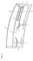
- Fig. 2 is a sectional view of the vehicle lamp taken along the line II-II in Fig. 1
- Fig. 3 is a sectional view of the vehicle lamp taken along the line III-III in Fig. 1 .
- a lamp compartment of the vehicle lamp 1 is formed by a substantially box-shaped frame 4 which is opened at a front side of the lamp and a front cover 40 which is disposed so as to cover the open side of the frame 4.
- the LEDs 2, 3, which are particular examples of light sources are mounted on the frame 4 so that light emitting surfaces thereof are oriented to the front (upwards in Figs. 2 , 3 ) of the vehicle lamp 1, whereby light is emitted to the front of the lamp.
- main reflectors 10 are formed integrally with a bottom side of the flame 4 (with a back side of the frame 4 that is opposite the front side of the lamp, according to the example shown in Fig. 3 ) so as to lie to sides of the LEDs 2, 3.
- Pluralities of primary reflecting surfaces 11, 12 are formed on the main reflectors 10 so as to be oriented to the front of the lamp so that light from the LEDs 2, 3 is projected to the front of the vehicle lamp 1.
- the pluralities of primary reflecting surfaces 11, 12 are aligned in a linear fashion so that the main reflectors 10 are formed into a belt-like shape in whole.
- each of the main reflectors 10 may have, when viewed from the front of the lamp, an outer circumferential edge that has a curved portion which becomes closer, in the vertical direction of the lamp, to the light source 2, 3 than other portions of said circumferential edge.
- Each of the primary reflecting surfaces 11, 12 may have, when viewed from the front of the lamp, an outer circumferential edge that is provided in the continuity of the outer circumferential edge of any other, adjacent reflecting surface 11, 12. More generally, the main reflectors 10 may be formed so that their respective primary reflecting surfaces 11, 12 lie continuous with each other.
- each of the primary reflecting surfaces 11, 12 may have, when viewed from the front of the lamp, two opposite, radial edges, each of which radially projects toward the corresponding light source 2, 3.
- the plurality of primary reflecting surfaces 11 are formed on the main reflector 10 so as to correspond to the LED 2 which constitutes the left-hand side LED, while the plurality of primary reflecting surfaces 12 are formed on the main reflector 10 so as to correspond to the LED 3 which constitutes the right-hand side LED when Fig. 1 is seen from the front.
- the primary reflecting surfaces 11, 12 are each formed into a stair step-like fashion continuously so that the respective reflecting surfaces are oriented towards the LEDs 2, 3.
- these pluralities of primary reflecting surfaces 11, 12 are arranged in the linear fashion in whole, so that the main reflectors 10 are formed into the belt-like shape in whole.
- the main reflectors 10 of this embodiment adopt a curvilinear design to enhance the design thereof.
- Areas on the bottom side of the frame 4 where the primary reflecting surfaces 11, 12 are not formed are mirror-finished, so as to enhance the aesthetic properties of the vehicle lamp 1 in whole.
- Sub-reflectors 20 are disposed in front of the LEDs 2, 3, respectively.
- Pluralities of secondary reflecting surfaces 21 are formed on the sub-reflectors 10 so as to be oriented to the rear of the lamp so that light from the LEDs 2, 3 is reflected towards the corresponding primary reflecting surfaces 11, 12.
- the total number of secondary reflecting surfaces 21 is equal to the total number of first reflecting surfaces 11, 12.
- the secondary reflecting surface 21 is formed into an ellipsoidal shape in which a first focal point is positioned at the LED 2 or 3 or in the vicinity thereof.
- the sub-reflector 20 is configured so that a group of secondary focal points of the plurality of secondary reflecting surfaces 21 are disposed in such a manner that an imaginary curve h which passes through the group of secondary focal points has a shape which corresponds to the shape of the main reflector 10. Consequently, the secondary reflecting surfaces 21 can reflect light from the LEDs 2, 3 towards the corresponding primary reflecting surfaces 11, 12 as intended.
- Fig. 4 is a front view of the vehicle lamp 1 with the front cover 40 and an inner lens 30 omitted for the sake of a better understandable illustration of the disposition of the second focal points of the secondary reflecting surfaces 21.
- the left-hand side LED 2, the primary reflecting surfaces 11 of the main reflector 10 and the sub-reflector 20 constitute one optical system
- the right-hand side LED 3, the primary reflecting surfaces 12 of the main reflector 10 and the sub-reflector 20 constitute another optical system.
- the reflector 10 which includes the primary reflecting surfaces 11 and the reflector 10 which includes the primary reflecting surfaces 12 are disposed adjacent to each other so that the primary reflecting surfaces 11 and the primary reflecting surfaces 12, which belong to different optical systems, are continuous with each other, and the reflectors 10 are integrated into a belt-like shape in whole. Even in the event that the vehicle lamp 1 includes several optical systems in the way described above, the primary reflecting surfaces 11 of one optical system, and the primary reflecting surfaces 12 of another optical system are arranged continuously so as to be integrated into a single unit in design, thereby making it possible to further enhance the design of the vehicle lamp 1.
- main reflectors 10 is provided so that two sets of main reflectors 10 are disposed vertically of the vehicle lamp 1 across the LEDs 2, 3.
- the main reflectors 10 are disposed symmetrically with respect to a straight line which passes through the LEDs 2, 3 horizontally to thereby enhance the design of the vehicle lamp 1.
- a transparent inner lens 30 is fixedly supported on the frame 4 in positions lying further forwards to the front of the lamp than the sub-reflectors 20.
- the inner lens 30 includes lens elements 31 which diffusely project light reflected on the primary reflecting surfaces 11, 12 to the front of the lamp.
- the lens element 31 is formed into a belt-like shape which corresponds to the main reflectors 10 which are formed into the belt-like shape.
- the inner lens 30 may have, when viewed from the front of the lamp, an outer circumferential edge that has a curved portion which becomes closer, in the vertical direction of the lamp, to the light sources 2, 3 than other portions of said circumferential edge.
- Said curved portion of the outer circumferential edge of the inner lens 30 may substantially corresponds to the curved portion of the outer circumferential edge of the main reflector 10.
- the extremum of the curved portion of the outer circumferential edge of the inner lens 30 and the extremum of the curved portion of the outer circumferential edge of the main reflector 10 may be substantially aligned in the horizontal direction of the vehicle lamp.
- the lens element 31 may be divided into a plurality of small lenses, so as to diffuse light efficiently. Additionally, in the case where the lens element 31 is divided into the plurality of small lenses, the lens element 31 can make a good contrast to the main reflectors 10 which are mirror finished to thereby enhance the design of the vehicle lamp 1.
- the transparent front cover 40 is provided further forwards to the front of the lamp than the inner lens 30, so as to protect an interior of the lamp.
- the primary reflecting surfaces 11, 12 are paraboloidal. Focal points of the primary reflecting surfaces 11, 12 which are paraboloidal are positioned at second focal points F of the secondary reflecting surfaces 21 or in the vicinity thereof, and the lens elements 31 of the inner lens 30 are disposed on axes of the primary reflecting surfaces 11, 12.
- the vehicle lamp 1 configured in the way that has been described heretofore, light rays can efficiently be emitted to the front of the lamp as indicated by optical paths L1 in Fig. 3 .
- the LEDs 2, 3 emit light radially.
- the secondary reflecting surfaces 21, which are ellipsoidal, of the sub-reflectors 20 reflect the light from the LEDs 2, 3, causing the light to pass near the secondary focal points F towards the primary reflecting surfaces 11, 12, which are paraboloidal.
- the primary reflecting surfaces 11, 12 reflect the light incident thereon to the front of the lamp as parallel light, and the lens elements 31 refract the parallel light so that the light so refracted is then emitted to the front of the lamp as diffuse light.
- light from the LEDs 2, 3 can be made to enter efficiently the main reflectors 10, which are designed into the complex shape such as the belt-like shape by utilizing many curves so as to enhance the design thereof, by the sub-reflectors 20 which include the secondary reflecting surfaces 21 whose secondary focal points F are aligned along the shape corresponding to the shape of the main reflectors 10.
- the main reflectors 10 are formed into the free shape as described above, by disposing the LEDs 2, 3 and the sub-reflectors 20 in positions which are not superposed on the main reflectors 10, light from the Lends 2, 3 can be emitted to the front from the main reflectors 10. Consequently, no special space where to dispose the LEDs 2, 3 has to be secured, the degree of freedom in designing the main reflector 10 being thereby enhanced.
- the main reflector 10 is formed into the complex shape, light from the LEDs 2, 3 can be reflected on the main reflectors 10 as designed by the sub-reflectors 20. Thus, light can be emitted to the front from the whole of the main reflectors 10 with as few LEDs 2, 3 as possible.
- the vehicle lamp 1 in which the two sets of main reflectors 10 which constitute the different optical systems laid adjacent horizontally are disposed vertically all the main reflectors 10 can be illuminated brightly by the two LEDs 2, 3. Consequently, the main reflectors 10, which are characteristic of the complex shape and the enhanced design, can be illuminate brightly.
- the required number of LEDs 2, 3 is small, and therefore, wiring installed for the LEDs 2, 3 does not have to be complex, and the production cost is not increased unreasonably.
- the reflecting surfaces 11, 12 of the main reflectors 10 which are situated away from the LEDs 2, 3 in outer circumferential edge positions (near side walls of the frame 4) of the vehicle lamp 1, for example, can also be illuminated brightly.
- the primary reflecting surfaces 11, 2 which are situated in the outer circumferential edge position of the frame 4 can be illuminated brightly without disposing particularly any additional light source.
- the main reflectors 10 can be formed on the bottom side of the frame 4, whereby an overall depth dimension of the vehicle lamp 1 can be reduced. Consequently, the vehicle lamp 1 can be provided which the enhanced design and which is compact in size.
- an additional LED (which is a particular example of an additional light source) 50 and an additional optical system which constitutes an additional optical member 60 which projects light from the additional LED 50 to the front of the lamp may be disposed on a front side 22 (for instance, the additional light source 50 may be disposed on a reverse side of the secondary reflecting surface 21) of the sub-reflector 20 in front of the main reflector 10 in positions where reflection light from the main reflector 10 is not cut off.
- light emitted from the additional LED 50 is emitted to the front as indicated by a light ray L3.
- light emitted from the additional LED 50 is guided to a light guide portion 62 by a light guiding reflecting portion 61 formed into a parabolic plane on the additional optical member 60.
- the light that has entered the light guide portion 62 is reflected by a plurality of minute reflecting elements 63 formed on a reverse side of the light guide portion 62 which faces the rear of the lamp for emission to the front of the lamp.
- the design of the vehicle lamp 1 is enhanced.
- the additional optical system illustrated is optional and does not necessarily have to be provided.
- the front side 22 of the sub-reflector 20 may be mirror finished or matt finished by embossing the front side 22, so that the vehicle lamp 1 is designed to have an external appearance which gives a simple impression to viewers.
- lens elements 31 are described as being provided on the inner lens 30, other configuration may of course be adopted in which the lens elements 31 are provided on the front cover 40 or no lens element 31 is provided so that reflection light from the main reflectors 10 is projected directly to the front.
- main reflectors 10 are described as being disposed axisymmetrically in the vertical direction with respect to the straight line which passes through the LEDs 2, 3, other configurations may of course be adopted in which the number of main reflectors 10 is increased or decreased, a plurality of main reflectors 10 are be disposed point symmetrically, and/or a single main reflector 10 is formed antisymmetrically or point symmetrically, depending upon a design required.
- Fig. 5 is a sectional view, similar to Fig. 3 , of a vehicle lamp 1A according to a modified example of the invention. Since this modified example is similar to the embodiment that has been described heretofore excluding the fact that primary reflecting surfaces 14 of main reflectors 10 are ellipsoidal, like reference numerals will be given to like members to those described in the embodiment, and the description thereof will be omitted herein.
- the primary reflecting surface 14 of the main reflector 10 is formed ellipsoidal.
- a first focal point F1 of the primary reflecting surface 14 is positioned at a second focal point of a secondary reflecting surface or in the vicinity of the second focal point, and a second focal point F2 is disposed on a lens element 31 of an inner lens 30 or in the vicinity of the lens element 31.
- the main reflector 10 is formed into a belt-like shape in which a plurality of primary reflecting surfaces 14 are aligned in a linear fashion and that the lens element 31 of the inner lens 30 is formed into a continuous belt-like shape which corresponds to the plurality of primary reflecting surfaces 14 so aligned.
- LEDs 2, 3 emit light radially
- secondary reflecting surfaces 21, which are ellipsoidal, of sub-reflectors 21 reflect light from the LEDs 2, 3, causing it to pass near the first focal points F1 towards the primary reflecting surfaces 14 which are ellipsoidal.
- the primary reflecting surfaces 14 reflect the light incident thereon, causing it to pass near the second focal points F2 which lie in the vicinity of the lens elements 31 towards the lens elements 31.
- the lens elements 31 refract the light incident thereon so that the light so refracted is emitted to the front of the lamp as diffuse light.
- the vehicle lamp 1A of the modified example of the invention too, light from the LEDs 2, 3 is allowed to enter the main reflectors 10 efficiently by the sub-reflectors 20 which include the secondary ellipsoidal reflecting surfaces 21 of which the second focal points F are aligned along the shape which corresponds to the main reflectors 10. Consequently, the vehicle lamp 1A can be provided in which the main reflectors 10 which each have the complex shape and the enhanced design can be illuminated brightly with as few the light sources as possible.
Landscapes
- Engineering & Computer Science (AREA)
- General Engineering & Computer Science (AREA)
- Physics & Mathematics (AREA)
- Microelectronics & Electronic Packaging (AREA)
- Optics & Photonics (AREA)
- Mechanical Engineering (AREA)
- Non-Portable Lighting Devices Or Systems Thereof (AREA)
Abstract
A vehicle lamp (1) includes: at least one light source (2, 3) which emits light to the front of the lamp; at least one main reflector (10) which projects the light from the light source (2, 3) to the front of the lamp and on which a plurality of primary reflecting surfaces (11, 12) are aligned; and at least one sub-reflector (20) which is disposed in a position lying in front of the light source (2, 3) and which includes a plurality of secondary reflecting surfaces (21) which reflect the light from the light source (2, 3) towards the corresponding primary reflecting surfaces (11, 12). The secondary reflecting surfaces (21) are each ellipsoidal. The secondary reflecting surfaces (21) are provided on the sub-reflector (20) so that their respective first focal points are positioned at the light source or in the vicinity thereof and their respective second focal points are aligned along a shape which corresponds to the main reflector (10).
Description
- Various designs of vehicle lamps have been proposed to enhance the appearance thereof.
- For example,
JP-A-2009-295552 JP-A-2010-267468 - When the ring-shaped light emitting element described in
JP-A-2009-295552 - Additionally, when the light sources are provided individually for the plurality of light emitting surfaces as done in
JP-A-2010-267468 - An object of the present invention is to provide a vehicle lamp which can provide sufficient illuminance with as few light sources as possible and which is well designed.
- Some embodiments of the present invention are as recited in any one of the appended claims.
- According to the vehicle lamp of the present invention, light from the at least one light source can be reflected efficiently by the at least one sub-reflector which includes the secondary reflecting surfaces in which the respective second focal points are aligned along the shape which correspond to the main reflector so as to be projected to the front from the main reflectors. Consequently, the vehicle lamp can be provided in which the main reflectors which are designed into the complex shape to enhance the design thereof can be illuminated brightly with as few the light sources as possible.
- A general configuration that implements various features of the invention will be described with reference to the drawings. The drawings and the associated descriptions are provided to illustrate some embodiments of the invention and thus do not limit the scope of the invention.
-
Fig. 1 is a front view of a vehicle lamp according to an embodiment of the invention. -
Fig. 2 is a sectional view taken along the line II-II inFig. 1 . -
Fig. 3 is a sectional view taken along the line III-III inFig. 1 . -
Fig. 4 is a front view of the vehicle lamp according to the embodiment of the invention. -
Fig. 5 is a sectional view that is similar to the view ofFig. 3 , and that represents a vehicle lamp according to a modified example of the invention. - Hereinafter, a vehicle lamp 1 according to a non-limitative, exemplary embodiment of the invention will be described by reference to the drawings.
-
Fig. 1 is a front view of a vehicle lamp 1. As shown inFig. 1 , the vehicle lamp 1 is configured so that light from a plurality of (two in this embodiment illustrated) LEDs (which are particular examples of light sources) 2, 3 is reflected atsub-reflectors 20, and further, reflection light from thesub-reflectors 20 are reflected to the front of the lamp bymain reflectors 10 which are formed into a belt-like shape, whereby reflection light reflected on themain reflectors 10 is emitted to the front of the lamp via aninner lens 30. -
Fig. 2 is a sectional view of the vehicle lamp taken along the line II-II inFig. 1 , andFig. 3 is a sectional view of the vehicle lamp taken along the line III-III inFig. 1 . - As shown in
Figs. 2 ,3 , a lamp compartment of the vehicle lamp 1 is formed by a substantially box-shaped frame 4 which is opened at a front side of the lamp and afront cover 40 which is disposed so as to cover the open side of theframe 4. In this lamp compartment, theLEDs frame 4 so that light emitting surfaces thereof are oriented to the front (upwards inFigs. 2 ,3 ) of the vehicle lamp 1, whereby light is emitted to the front of the lamp. - Referring to
Figs. 1 ann 3,main reflectors 10 are formed integrally with a bottom side of the flame 4 (with a back side of theframe 4 that is opposite the front side of the lamp, according to the example shown inFig. 3 ) so as to lie to sides of theLEDs surfaces main reflectors 10 so as to be oriented to the front of the lamp so that light from theLEDs - In the present embodiment, the pluralities of
primary reflecting surfaces main reflectors 10 are formed into a belt-like shape in whole. - For instance, as shown in
Fig. 1 , each of themain reflectors 10 may have, when viewed from the front of the lamp, an outer circumferential edge that has a curved portion which becomes closer, in the vertical direction of the lamp, to thelight source - Each of the
primary reflecting surfaces surface main reflectors 10 may be formed so that their respective primary reflectingsurfaces - In addition, as shown in the example of
Fig. 1 , each of theprimary reflecting surfaces corresponding light source - As shown in
Fig. 1 , the plurality of primary reflectingsurfaces 11 are formed on themain reflector 10 so as to correspond to theLED 2 which constitutes the left-hand side LED, while the plurality of primary reflectingsurfaces 12 are formed on themain reflector 10 so as to correspond to theLED 3 which constitutes the right-hand side LED whenFig. 1 is seen from the front. Theprimary reflecting surfaces LEDs - Additionally, as shown in
Fig. 1 , these pluralities of primary reflectingsurfaces main reflectors 10 are formed into the belt-like shape in whole. In this way, themain reflectors 10 of this embodiment adopt a curvilinear design to enhance the design thereof. Areas on the bottom side of theframe 4 where the primary reflectingsurfaces -
Sub-reflectors 20 are disposed in front of theLEDs surfaces 21 are formed on thesub-reflectors 10 so as to be oriented to the rear of the lamp so that light from theLEDs primary reflecting surfaces surfaces 21 is equal to the total number of first reflectingsurfaces - As shown in
Fig. 3 , the secondary reflectingsurface 21 is formed into an ellipsoidal shape in which a first focal point is positioned at theLED Fig. 4 , as a whole, thesub-reflector 20 is configured so that a group of secondary focal points of the plurality ofsecondary reflecting surfaces 21 are disposed in such a manner that an imaginary curve h which passes through the group of secondary focal points has a shape which corresponds to the shape of themain reflector 10. Consequently, the secondary reflectingsurfaces 21 can reflect light from theLEDs primary reflecting surfaces Fig. 4 is a front view of the vehicle lamp 1 with thefront cover 40 and aninner lens 30 omitted for the sake of a better understandable illustration of the disposition of the second focal points of the secondary reflectingsurfaces 21. - In this embodiment, the left-
hand side LED 2, the primary reflectingsurfaces 11 of themain reflector 10 and thesub-reflector 20 constitute one optical system, and the right-hand side LED 3, the primary reflectingsurfaces 12 of themain reflector 10 and thesub-reflector 20 constitute another optical system. - The
reflector 10 which includes theprimary reflecting surfaces 11 and thereflector 10 which includes the primary reflectingsurfaces 12 are disposed adjacent to each other so that theprimary reflecting surfaces 11 and the primary reflectingsurfaces 12, which belong to different optical systems, are continuous with each other, and thereflectors 10 are integrated into a belt-like shape in whole. Even in the event that the vehicle lamp 1 includes several optical systems in the way described above, the primary reflectingsurfaces 11 of one optical system, and the primary reflectingsurfaces 12 of another optical system are arranged continuously so as to be integrated into a single unit in design, thereby making it possible to further enhance the design of the vehicle lamp 1. - In addition, another set of
main reflectors 10 is provided so that two sets ofmain reflectors 10 are disposed vertically of the vehicle lamp 1 across theLEDs main reflectors 10 are disposed symmetrically with respect to a straight line which passes through theLEDs - A transparent
inner lens 30 is fixedly supported on theframe 4 in positions lying further forwards to the front of the lamp than thesub-reflectors 20. Theinner lens 30 includeslens elements 31 which diffusely project light reflected on theprimary reflecting surfaces lens element 31 is formed into a belt-like shape which corresponds to themain reflectors 10 which are formed into the belt-like shape. - For instance, as shown in
Fig. 1 , theinner lens 30 may have, when viewed from the front of the lamp, an outer circumferential edge that has a curved portion which becomes closer, in the vertical direction of the lamp, to thelight sources - Said curved portion of the outer circumferential edge of the
inner lens 30 may substantially corresponds to the curved portion of the outer circumferential edge of themain reflector 10. In particular, the extremum of the curved portion of the outer circumferential edge of theinner lens 30 and the extremum of the curved portion of the outer circumferential edge of themain reflector 10 may be substantially aligned in the horizontal direction of the vehicle lamp. - The
lens element 31 may be divided into a plurality of small lenses, so as to diffuse light efficiently. Additionally, in the case where thelens element 31 is divided into the plurality of small lenses, thelens element 31 can make a good contrast to themain reflectors 10 which are mirror finished to thereby enhance the design of the vehicle lamp 1. - The
transparent front cover 40 is provided further forwards to the front of the lamp than theinner lens 30, so as to protect an interior of the lamp. - Further, in this embodiment, as shown in
Fig. 3 , theprimary reflecting surfaces surfaces surfaces 21 or in the vicinity thereof, and thelens elements 31 of theinner lens 30 are disposed on axes of theprimary reflecting surfaces - According to the vehicle lamp 1 configured in the way that has been described heretofore, light rays can efficiently be emitted to the front of the lamp as indicated by optical paths L1 in
Fig. 3 . In particular, theLEDs surfaces 21, which are ellipsoidal, of the sub-reflectors 20 reflect the light from theLEDs primary reflecting surfaces primary reflecting surfaces lens elements 31 refract the parallel light so that the light so refracted is then emitted to the front of the lamp as diffuse light. - According to the vehicle lamp 1 of the embodiment that has been described heretofore, light from the
LEDs main reflectors 10, which are designed into the complex shape such as the belt-like shape by utilizing many curves so as to enhance the design thereof, by the sub-reflectors 20 which include the secondary reflectingsurfaces 21 whose secondary focal points F are aligned along the shape corresponding to the shape of themain reflectors 10. - In addition, even in the event that the
main reflectors 10 are formed into the free shape as described above, by disposing theLEDs main reflectors 10, light from the Lends 2, 3 can be emitted to the front from themain reflectors 10. Consequently, no special space where to dispose theLEDs main reflector 10 being thereby enhanced. - Additionally, even in the event that the
main reflector 10 is formed into the complex shape, light from theLEDs main reflectors 10 as designed by the sub-reflectors 20. Thus, light can be emitted to the front from the whole of themain reflectors 10 with asfew LEDs - For example, according to this embodiment, in the vehicle lamp 1 in which the two sets of
main reflectors 10 which constitute the different optical systems laid adjacent horizontally are disposed vertically, all themain reflectors 10 can be illuminated brightly by the twoLEDs main reflectors 10, which are characteristic of the complex shape and the enhanced design, can be illuminate brightly. Thus, the required number ofLEDs LEDs - Additionally, light from the LEDs can be reflected to the designed positions efficiently by the secondary reflecting
surfaces 21 of the sub-reflectors 20. Therefore, the reflectingsurfaces main reflectors 10 which are situated away from theLEDs primary reflecting surfaces frame 4 can be illuminated brightly without disposing particularly any additional light source. - Further, by allowing light from the
LEDs LEDs main reflectors 10 can be formed on the bottom side of theframe 4, whereby an overall depth dimension of the vehicle lamp 1 can be reduced. Consequently, the vehicle lamp 1 can be provided which the enhanced design and which is compact in size. - Thus, while the invention has been described by reference to the particular embodiment above, the technical scope of the invention is limited to that particular embodiment. It is obvious two those skilled in the art to which the invention pertains that various modification or improvements can be carried out without departing from the scope of the invention.
- For example, as shown in the accompanying drawings, an additional LED (which is a particular example of an additional light source) 50 and an additional optical system which constitutes an additional
optical member 60 which projects light from theadditional LED 50 to the front of the lamp may be disposed on a front side 22 (for instance, the additionallight source 50 may be disposed on a reverse side of the secondary reflecting surface 21) of the sub-reflector 20 in front of themain reflector 10 in positions where reflection light from themain reflector 10 is not cut off. - No light from the
LEDs front side 22 of the sub-reflector 20. Therefore, neither theadditional LED 50 nor the additionaloptical member 60 cuts off light from theLEDs front side 22 of the sub-reflector 20 is visualized from an exterior portion via thefront cover 40 and theinner lens 30. Therefore, by disposing the additional optical system on thefront side 22 of the sub-reflector 20, the design of the vehicle lamp 1 can be enhanced further. - In this embodiment, as shown in
Fig. 2 , light emitted from theadditional LED 50 is emitted to the front as indicated by a light ray L3. Namely, light emitted from theadditional LED 50 is guided to alight guide portion 62 by a lightguiding reflecting portion 61 formed into a parabolic plane on the additionaloptical member 60. The light that has entered thelight guide portion 62 is reflected by a plurality of minute reflecting elements 63 formed on a reverse side of thelight guide portion 62 which faces the rear of the lamp for emission to the front of the lamp. In this embodiment, by combination of thelight guide portion 62 which is formed into a straight line and the curvedmain reflectors 10, the design of the vehicle lamp 1 is enhanced. - It is to be noted that the additional optical system illustrated is optional and does not necessarily have to be provided. For instance, as an alternative, the
front side 22 of the sub-reflector 20 may be mirror finished or matt finished by embossing thefront side 22, so that the vehicle lamp 1 is designed to have an external appearance which gives a simple impression to viewers. - Additionally, in the embodiment above, while the
lens elements 31 are described as being provided on theinner lens 30, other configuration may of course be adopted in which thelens elements 31 are provided on thefront cover 40 or nolens element 31 is provided so that reflection light from themain reflectors 10 is projected directly to the front. - In addition, in the above, while the two sets of
main reflectors 10 are described as being disposed axisymmetrically in the vertical direction with respect to the straight line which passes through theLEDs main reflectors 10 is increased or decreased, a plurality ofmain reflectors 10 are be disposed point symmetrically, and/or a singlemain reflector 10 is formed antisymmetrically or point symmetrically, depending upon a design required. - In the embodiment above, while the
primary reflecting surfaces Fig. 5 is a sectional view, similar toFig. 3 , of avehicle lamp 1A according to a modified example of the invention. Since this modified example is similar to the embodiment that has been described heretofore excluding the fact that primary reflectingsurfaces 14 ofmain reflectors 10 are ellipsoidal, like reference numerals will be given to like members to those described in the embodiment, and the description thereof will be omitted herein. - The
primary reflecting surface 14 of themain reflector 10 is formed ellipsoidal. A first focal point F1 of theprimary reflecting surface 14 is positioned at a second focal point of a secondary reflecting surface or in the vicinity of the second focal point, and a second focal point F2 is disposed on alens element 31 of aninner lens 30 or in the vicinity of thelens element 31. It is similar to the embodiment above that themain reflector 10 is formed into a belt-like shape in which a plurality of primary reflectingsurfaces 14 are aligned in a linear fashion and that thelens element 31 of theinner lens 30 is formed into a continuous belt-like shape which corresponds to the plurality of primary reflectingsurfaces 14 so aligned. - In the
vehicle lamp 1A according to the modified example which is configured in the way described above, too, light rays can be emitted to the front of the lamp efficiently as indicated by light rays L2 inFig. 5 . Namely,LEDs surfaces 21, which are ellipsoidal, of sub-reflectors 21 reflect light from theLEDs primary reflecting surfaces 14 which are ellipsoidal. Theprimary reflecting surfaces 14 reflect the light incident thereon, causing it to pass near the second focal points F2 which lie in the vicinity of thelens elements 31 towards thelens elements 31. Then, thelens elements 31 refract the light incident thereon so that the light so refracted is emitted to the front of the lamp as diffuse light. - In this way, according to the
vehicle lamp 1A of the modified example of the invention, too, light from theLEDs main reflectors 10 efficiently by the sub-reflectors 20 which include the secondaryellipsoidal reflecting surfaces 21 of which the second focal points F are aligned along the shape which corresponds to themain reflectors 10. Consequently, thevehicle lamp 1A can be provided in which themain reflectors 10 which each have the complex shape and the enhanced design can be illuminated brightly with as few the light sources as possible.
Claims (10)
- A vehicle lamp (1, 1A) comprising:at least one light source (2, 3) which emits light to the front of the lamp;at least one main reflector (10) which includes a plurality of primary reflecting surfaces (11, 12) that are aligned; andat least one sub-reflector (20) which is disposed in a position lying in front of the light source (2, 3) and which includes a plurality of secondary reflecting surfaces (21),
whereinthe secondary reflecting surfaces (21) are configured to reflect the light from the light source (2, 3) towards the corresponding primary reflecting surfaces (11, 12),the primary reflecting surfaces (11, 12) are configured to project the reflection light from the sub-reflector (20) to the front of the lamp,the secondary reflecting surfaces (21) are each ellipsoidal, andthe secondary reflecting surfaces (21) are provided on the sub-reflector (20) so that their respective first focal points positioned at the light source (2, 3) or in the vicinity thereof and their respective second focal points are disposed along a shape which corresponds to the shape of the main reflector (10). - The vehicle lamp according to Claim 1, comprising several light sources (2, 3), several main reflectors (10), and several sub-reflectors (20) which form together a plurality of optical systems, each of said optical system comprising one of said light sources (2, 3), one of said main reflectors (10), and one of said sub-reflectors (20), wherein
said main reflectors (10) are disposed adjacent to each other so that their respective primary reflecting surfaces (11, 12) are continuous with each other. - The vehicle lamp according to Claim 1 or 2, wherein
the main reflector (10) has a belt-like shape in which the primary reflecting surfaces (11, 12) are disposed in a linear fashion. - The vehicle lamp according to any one of Claims 1 to 3, wherein
the primary reflecting surfaces (11, 12) are each paraboloidal, and
respective focal points of the primary reflecting surfaces (11, 12) are each positioned at the corresponding second focal points or in the vicinity of the corresponding second focal points of the secondary reflecting surfaces (21). - The vehicle lamp according to Claim 4, comprising a lens member (30) which has a plurality of lens elements (31) which are disposed individually on corresponding axes of the paraboloidal primary reflecting surf aces (11, 12) and which diffusely project reflection light from the primary reflecting surfaces (11, 12) to the front of the lamp.
- The vehicle lamp according to Claim 5, wherein the lens elements (31) have a continuous belt-like shape which corresponds to the shape of the plurality of primary reflecting surfaces.
- The vehicle lamp according to any one of Claims 1 to 3, wherein
the primary reflecting surfaces (11, 12) are each ellipsoidal,
respective first focal points of the primary reflecting surfaces (11, 12) are each positioned at the corresponding second focal points or in the vicinity of the corresponding second focal points of the secondary reflecting surfaces (21). - The vehicle lamp according to Claim 7, comprising a lens member (30) which has a plurality of lens elements (31) which are disposed at corresponding second focal points of or in the vicinity of the corresponding second focal points of the primary reflecting surfaces (11, 12'), and which diffusely project reflection light from the primary reflecting surfaces (11, 12) to the front of the lamp.
- The vehicle lamp according to Claim 8, wherein the lens elements (31) have a continuous belt-like shape which corresponds to the shape of the plurality of primary reflecting surfaces.
- The vehicle lamp according to any one of Claims 1 to 9, comprising:an additional light source (50) and an additional optical member (60) which projects light from the additional light source (50) to the front of the lamp, said additional light source (50) and additional optical member (60) being provided in front of the main reflector (10) in a position where reflection light from the main reflector is not cut off.
Applications Claiming Priority (1)
| Application Number | Priority Date | Filing Date | Title |
|---|---|---|---|
| JP2011099072A JP2012230843A (en) | 2011-04-27 | 2011-04-27 | Vehicle lamp |
Publications (1)
| Publication Number | Publication Date |
|---|---|
| EP2518391A2 true EP2518391A2 (en) | 2012-10-31 |
Family
ID=46044471
Family Applications (1)
| Application Number | Title | Priority Date | Filing Date |
|---|---|---|---|
| EP12165540A Withdrawn EP2518391A2 (en) | 2011-04-27 | 2012-04-25 | Vehicle lamp |
Country Status (2)
| Country | Link |
|---|---|
| EP (1) | EP2518391A2 (en) |
| JP (1) | JP2012230843A (en) |
Cited By (3)
| Publication number | Priority date | Publication date | Assignee | Title |
|---|---|---|---|---|
| CN111412430A (en) * | 2020-04-17 | 2020-07-14 | 慈溪市广联汽车配件有限公司 | A hemispherical reflection high beam of a car |
| CN115707902A (en) * | 2021-08-20 | 2023-02-21 | 华域视觉科技(上海)有限公司 | ADB (alternating direct bus) high-beam and low-beam integrated car lamp lighting module and car lamp |
| WO2023019568A1 (en) * | 2021-08-20 | 2023-02-23 | 华域视觉科技(上海)有限公司 | Vehicle lamp lighting module and vehicle lamp |
Families Citing this family (1)
| Publication number | Priority date | Publication date | Assignee | Title |
|---|---|---|---|---|
| WO2017169141A1 (en) | 2016-03-31 | 2017-10-05 | 本田技研工業株式会社 | Vehicular lamp device |
Citations (2)
| Publication number | Priority date | Publication date | Assignee | Title |
|---|---|---|---|---|
| JP2009295552A (en) | 2008-06-09 | 2009-12-17 | Stanley Electric Co Ltd | Lighting system using ring-like illuminant |
| JP2010267468A (en) | 2009-05-14 | 2010-11-25 | Koito Mfg Co Ltd | Vehicle lighting |
-
2011
- 2011-04-27 JP JP2011099072A patent/JP2012230843A/en not_active Withdrawn
-
2012
- 2012-04-25 EP EP12165540A patent/EP2518391A2/en not_active Withdrawn
Patent Citations (2)
| Publication number | Priority date | Publication date | Assignee | Title |
|---|---|---|---|---|
| JP2009295552A (en) | 2008-06-09 | 2009-12-17 | Stanley Electric Co Ltd | Lighting system using ring-like illuminant |
| JP2010267468A (en) | 2009-05-14 | 2010-11-25 | Koito Mfg Co Ltd | Vehicle lighting |
Cited By (3)
| Publication number | Priority date | Publication date | Assignee | Title |
|---|---|---|---|---|
| CN111412430A (en) * | 2020-04-17 | 2020-07-14 | 慈溪市广联汽车配件有限公司 | A hemispherical reflection high beam of a car |
| CN115707902A (en) * | 2021-08-20 | 2023-02-21 | 华域视觉科技(上海)有限公司 | ADB (alternating direct bus) high-beam and low-beam integrated car lamp lighting module and car lamp |
| WO2023019568A1 (en) * | 2021-08-20 | 2023-02-23 | 华域视觉科技(上海)有限公司 | Vehicle lamp lighting module and vehicle lamp |
Also Published As
| Publication number | Publication date |
|---|---|
| JP2012230843A (en) | 2012-11-22 |
Similar Documents
| Publication | Publication Date | Title |
|---|---|---|
| US8870423B2 (en) | Vehicle decorative lighting device and vehicle lamp | |
| US8007149B2 (en) | Vehicle lighting assembly and light guiding lens for use in vehicle lighting assembly | |
| EP2568320B1 (en) | Vehicle lamp | |
| US10036528B2 (en) | Vehicle combination lamp | |
| US10119673B2 (en) | Vehicle lighting device for illuminating in a first and second direction | |
| KR101957390B1 (en) | Overhead console and vehicle-body upper structure | |
| JP2019096614A (en) | Vehicular lighting tool | |
| US8714794B2 (en) | Vehicle lamp | |
| JP6584302B2 (en) | Light guide and vehicle lamp | |
| JP6616669B2 (en) | Light guide and vehicle lamp | |
| EP2518391A2 (en) | Vehicle lamp | |
| JP5668920B2 (en) | Lighting device | |
| JP2015076249A (en) | Vehicular lighting fixture | |
| JP7218039B2 (en) | Light guide member for vehicle, lamp for vehicle | |
| JP2016046114A (en) | Vehicle lighting | |
| US9862306B2 (en) | Vehicle decorative lighting device and vehicle lamp | |
| JP2015153577A (en) | vehicle lamp | |
| JP2014159257A (en) | Lamp | |
| JP2013122872A (en) | Illumination lamp fitting for vehicle | |
| KR102064342B1 (en) | Light source and lamp for vehicle having the same | |
| JP2009009745A (en) | Vehicle lighting | |
| JP6221438B2 (en) | Vehicle lighting | |
| JP2018113133A (en) | Light guide and lighting fixture | |
| JP7506525B2 (en) | Vehicle lighting fixture and headlamp assembly | |
| JP6035901B2 (en) | Vehicle lighting |
Legal Events
| Date | Code | Title | Description |
|---|---|---|---|
| PUAI | Public reference made under article 153(3) epc to a published international application that has entered the european phase |
Free format text: ORIGINAL CODE: 0009012 |
|
| 17P | Request for examination filed |
Effective date: 20120425 |
|
| AK | Designated contracting states |
Kind code of ref document: A2 Designated state(s): AL AT BE BG CH CY CZ DE DK EE ES FI FR GB GR HR HU IE IS IT LI LT LU LV MC MK MT NL NO PL PT RO RS SE SI SK SM TR |
|
| AX | Request for extension of the european patent |
Extension state: BA ME |
|
| STAA | Information on the status of an ep patent application or granted ep patent |
Free format text: STATUS: THE APPLICATION HAS BEEN WITHDRAWN |
|
| 18W | Application withdrawn |
Effective date: 20160720 |