EP2518369A1 - Drive train for a vehicle and method to control a drive train for a vehicle - Google Patents
Drive train for a vehicle and method to control a drive train for a vehicle Download PDFInfo
- Publication number
- EP2518369A1 EP2518369A1 EP11164055A EP11164055A EP2518369A1 EP 2518369 A1 EP2518369 A1 EP 2518369A1 EP 11164055 A EP11164055 A EP 11164055A EP 11164055 A EP11164055 A EP 11164055A EP 2518369 A1 EP2518369 A1 EP 2518369A1
- Authority
- EP
- European Patent Office
- Prior art keywords
- transmission
- transmission mechanism
- additional
- drive train
- additional transmission
- Prior art date
- Legal status (The legal status is an assumption and is not a legal conclusion. Google has not performed a legal analysis and makes no representation as to the accuracy of the status listed.)
- Granted
Links
Images

Classifications
-
- F—MECHANICAL ENGINEERING; LIGHTING; HEATING; WEAPONS; BLASTING
- F16—ENGINEERING ELEMENTS AND UNITS; GENERAL MEASURES FOR PRODUCING AND MAINTAINING EFFECTIVE FUNCTIONING OF MACHINES OR INSTALLATIONS; THERMAL INSULATION IN GENERAL
- F16H—GEARING
- F16H37/00—Combinations of mechanical gearings, not provided for in groups F16H1/00 - F16H35/00
- F16H37/02—Combinations of mechanical gearings, not provided for in groups F16H1/00 - F16H35/00 comprising essentially only toothed or friction gearings
- F16H37/04—Combinations of toothed gearings only
- F16H37/042—Combinations of toothed gearings only change gear transmissions in group arrangement
- F16H37/043—Combinations of toothed gearings only change gear transmissions in group arrangement without gears having orbital motion
-
- F—MECHANICAL ENGINEERING; LIGHTING; HEATING; WEAPONS; BLASTING
- F16—ENGINEERING ELEMENTS AND UNITS; GENERAL MEASURES FOR PRODUCING AND MAINTAINING EFFECTIVE FUNCTIONING OF MACHINES OR INSTALLATIONS; THERMAL INSULATION IN GENERAL
- F16H—GEARING
- F16H37/00—Combinations of mechanical gearings, not provided for in groups F16H1/00 - F16H35/00
- F16H37/02—Combinations of mechanical gearings, not provided for in groups F16H1/00 - F16H35/00 comprising essentially only toothed or friction gearings
- F16H37/04—Combinations of toothed gearings only
- F16H37/042—Combinations of toothed gearings only change gear transmissions in group arrangement
- F16H37/043—Combinations of toothed gearings only change gear transmissions in group arrangement without gears having orbital motion
- F16H2037/045—Combinations of toothed gearings only change gear transmissions in group arrangement without gears having orbital motion comprising a separate gearing unit for shifting between high and low ratio range
Definitions
- the present invention relates to the field of automotive technology and especially to the field of drive trains.
- a standard drive train for a vehicle comprises a combustion engine, a main transmission and a rotatable mass, such as a flywheel or a torque converter, arranged there between.
- the rotatable mass absorbs oscillations caused by irregularities from the combustion engine. The dampening of the oscillations is essential to avoid load spikes in the transmission and that the gears in the transmissions chatter.
- a clutch is arranged between the output shaft of the combustion engine and the input shaft of the transmission.
- the clutch is disengaged.
- the speed of the output shaft of the engine and the speed of the input shaft of the transmission has to be synchronised after the gear change. If the transmission has changed from a lower to a higher gear, the speed of the drive shaft of the engine has to decrease and if the transmission has changed from a higher gear to a lower gear, the speed of the engine, and thereby also the flywheel, has to be increased before the engagement of the clutch.
- the flywheel can have an inertia about 10 times of the inertia of the engine.
- the object of the present invention is to provide an inventive drive train and method to control said drive train, which increases the efficiency of the drive train.
- the invention rest upon the idea, that a gear switch is performed in order to increase/decrease the speed of the engine and without accelerating a rotating mass, i.e. a flywheel or a torque converter. Benefits there from would be fast response times when more power is demanded from the engine and better emissions, since the engine can be operated at an optimal speed.
- the inventive drive train is adapted for a vehicle, and comprises at least a combustion engine, a main transmission and a rotatable mass, such as a flywheel or a torque converter, arranged there between.
- a rotatable mass such as a flywheel or a torque converter
- the inventive drive train is characterised in, that an additional transmission mechanism is arranged in the power flow in between the main transmission and the engine.
- Said additional transmission mechanism is provided with at least a first and a second transmission ratio and wherein said first transmission ratio is higher than said second transmission ratio.
- the additional transmission mechanism can be shifted between the first and the second transmission ratio in order to increase or decrease the engine speed and simultaneously keeping the speed of said rotatable mass and masses in the main transmission unaffected thereof, i.e. without accelerating said rotatable mass or any masses in the main transmission.
- the speed of the engine is changed, i.e. increased or decreased, depending of in what direction the gear change has been performed. Because the engine does not have to accelerate any masses and thereby just accelerate/decelerate its own inertia, the gear change can be performed much quicker than a traditional gear change.
- the quick gear change can be used during driving to increase the torque from the engine, without performing a traditional gear change. Further, the engine can due to the inventive additional transmission mechanism be driven in a more narrow speed range, which is beneficial considering fuel efficiency and emissions.
- the additional transmission mechanism can be used in combination of a manual transmission, an automated manual transmission or an automatic transmission as a main transmission.
- the control of the additional transmission is controlled by a vehicle management system (VMS) or one of its subsystems, such as a transmission management system (TMS) and/or engine management system (EMS).
- VMS vehicle management system
- TMS transmission management system
- EMS engine management system
- the additional transmission mechanism is arranged in the power flow between the combustion engine and the rotatable mass. Because the additional transmission mechanism is arranged in the power flow before the rotatable mass, the combustion engine is disconnected from the rotatable mass during a gear shifting operation of the additional transmission, wherein the combustion engine just has to accelerate/decelerate its own inertia.
- the additional transmission mechanism is provided in the power flow in between the rotatable mass and the main transmission.
- the rotatable mass is provided with a clutch, such that said clutch can be disengaged and the rotatable mass be detached from the rotation of the drive train before a transmission ratio change of the additional transmission mechanism is performed, and wherein said clutch can be engaged and the rotatable mass rotates with the drive train after a transmission ratio change of the additional transmission mechanism has been performed. Due to the possibility to engage and disengage the rotatable mass, it does not have to be accelerated or decelerated during a transmission ratio change of the additional transmission mechanism.
- the second embodiment of the invention provides the same benefits as the first embodiment. Further, an additional advantage of this second embodiment of the invention over said first embodiment is that the additional transmission is not subjected to the oscillations of the combustion engine, due to its placement in the power flow, after the rotatable mass, which absorb these oscillations.
- the additional transmission mechanism and the main transmission is subjected to the oscillations caused by the combustion engine.
- the additional transmission performs the change of transmission ratio, wherein the drive line is open.
- the time interval during which the additional transmission and the main transmission is exposed to the oscillations are so short that the it won't be noticeable for a drive or a passenger of the vehicle, i.e. can be neglected.
- the additional transmission mechanism is provided with a scissors gearing.
- a scissor gearing could be provided in both of the first and second embodiment of the invention.
- a scissors gearing prevent a rattling noise in the gearing mechanism caused by oscillations in the drive train.
- the additional transmission mechanism is preferably a planetary gearing or a gear step, other possibilities are a variator of any kind.
- a planetary gearing is a better solution, which however can be too expensive.
- a gear step is the more cost effective solution.
- a preferred first transmission ratio is a direct drive, i.e. 1:1, and a second transmission ratio could for example be 1:2. It is preferable in to have a direct drive as a first transmission ratio, because the friction losses are at lowest with a direct drive.
- the second transmission ratio however, is not bound to be 1:2, the second transmission ration is rather to be chosen dependent of what is most beneficial for the total powertrain installation.
- the drive train is controlled by a vehicle management system (VMS), which therefore also controls the additional transmission mechanism.
- VMS vehicle management system
- a VMS comprises normally of several sub-management systems such as transmission management system and engine management system, the hierarchy of the management systems are well known and not the scope of this invention, wherein the subject won't be discussed further.
- the additional transmission mechanism is to be fully automatic and controlled by the VMS, such that the drive cannot actively change between the transmission ratio of the additional transmission mechanism. Still the additional transmission mechanism is fully functional with either of an automated, an automatic or a manual transmission.
- the method comprises the steps of:
- fast transmission ratio changes can are made by the additional transmission mechanism in between the ordinary gear changes by the main transmission, the combustion engine can thereby be held within a more narrow speed range, at which a higher torque is available, the efficiency of the drive line is increased and the emissions decreased.
- the additional transmission mechanism can be used with all speeds of the main transmission.
- the rotatable mass is disengaged from the drive train before the additional transmission changes its transmission ratio.
- This method step is essential when the additional transmission mechanism is arranged in the power flow between the rotatable mass and the transmission, in order to avoid an acceleration or deceleration of the rotatable mass during a gear shift.
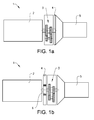
- Figure 1 shows a schematic drawing of the invention
- in fig. 1a is a first embodiment of the invention illustrated
- in fig. 1b is a second embodiment of the invention illustrated.
- the drive line 1 according to the first and second embodiment of the invention comprises; a combustion engine 2, an additional transmission mechanism 3, a rotatable mass 4 and a main transmission 5
- the additional transmission mechanism 3 is arranged in the power flow between the combustion engine 2 and the rotatable mass 4.
- the additional transmission mechanism 3 is arranged in the power flow between the rotatable mass 4 and the main transmission 5.
- the rotational mass 4 might be a torque converter in the first embodiment and a flywheel in the second embodiment. This however, is secondary and not an essential part of the invention, the additional transmission mechanism 3 is suitable to use with any rotatable mass 4.
- a transmission ratio change of the additional transmission mechanism 3 does not accelerate or decelerate the rotatable mass 4, wherein this change can be made very quickly, i.e. about the same time needed to open the throttle.
- the rotatable mass 4 is arranged in the power flow before the additional transmission mechanism 3, wherein to enable a transmission ratio change of the additional transmission mechanism 3, without accelerating or decelerating the rotatable mass 4, the rotatable mass for is attached with the drive train 1 with a clutch 6, wherein the clutch 6 disengages during a gear change of the additional transmission mechanism 3.
- the clutch 6 engages immediately after the gear change of the additional transmission mechanism is performed, wherein the rotatable mass 4 is accelerated to the output speed of the engine 2.
- the drive line 1 is closed, the rotatable mass 4 is accelerated/decelerated by the whole kinetic energy of the vehicle, in comparison with which the mass of the rotatable mass is negligible.
- the clutch 6 may be any clutch device suitable for the task. Clutches engaging and disengaging a rotatable mass to/from a shaft are known and won't be further described here.
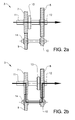
- Fig. 2a and 2b discloses a schematic design example of an additional transmission mechanism 3.
- the additional transmission mechanism 2 according to the example comprises four gear wheels 7, 8, 9, 10, a clutch 13 and a one way clutch 14.
- the additional transmission mechanism 3 transmits power over the first transmission ratio (1:1)
- the additional transmission mechanism 3 transmits power over the second transmission ration.
- the second transmission ratio can for example be 1:2.
- the clutch 13 engages and disengages.
- the clutch 12 is engaged and connects the output shaft 11 of the combustion engine 2 directly to the input shaft 12 of the transmission 5, wherein the one way clutch 14 freewheels.
- the invention is not limited to the specific design example of the additional gearing 3 shown in the figures, but includes all variation within the scope of the present claims.
- the additional transmission mechanism 3 can have any suitable number of gearwheels and the clutches 13, 14 can be differently arranged and/or designed, as long as the additional transmission mechanism 3 can perform the transmission ratio change needed for the invention.
- Other possible additional transmission mechanisms 3 are planetary gearing or belt variator or any other kind of variator.
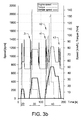
- fig. 3a and 3b are two schematic diagrams shown with a simulation of a new European driving cycle (NEDC), wherein just the urban driving cycle (UDC) for a vehicle shown.
- NEDC European driving cycle
- UDC urban driving cycle
- Fig. 3a shows the driving cycle for an ordinary vehicle
- fig. 3b shows the same driving cycle for a vehicle with an inventive additional transmission mechanism 3.
- a third start stop 40 at which the vehicle is accelerated to about 50 km/h, whereby two gear changes 41, 42 are performed by the main transmission 5 during the acceleration and one gear change 43 is performed by the main transmission 5 during the deceleration.
- the gear changes by the main transmission 5 are performed with the same timing in both fig. 3a and fig. 3b .
- the speed of the engine is held lower in fig. 3b , due to the additional transmissions mechanisms transmission ratio changes, whereby a higher torque is available.
- the additional transmission 3 strives to keep the speed of the engine 2 is held low to reduce friction and pumping losses, whereby the additional transmission 3 automatically performs a transmission ratio change from the second transmission ratio to the first transmission ratio when the speed of the engine 2 becomes too low, i.e. during a retardation of the vehicle.
- the vehicle is driven with a lower engine speed and a higher torque, whereby the engine reaches a better efficiency; this is due to the inventive additional transmission and the method to control the additional transmission 3.
- the additional transmission 3 can be used in combination with all the gears of the main transmission 5.
Landscapes
- Engineering & Computer Science (AREA)
- General Engineering & Computer Science (AREA)
- Mechanical Engineering (AREA)
- Control Of Transmission Device (AREA)
- Transmission Devices (AREA)
Abstract

Description
- The present invention relates to the field of automotive technology and especially to the field of drive trains.
- A standard drive train for a vehicle comprises a combustion engine, a main transmission and a rotatable mass, such as a flywheel or a torque converter, arranged there between. The rotatable mass absorbs oscillations caused by irregularities from the combustion engine. The dampening of the oscillations is essential to avoid load spikes in the transmission and that the gears in the transmissions chatter.
- It is desired to drive the engine at an optimal speed, at which the engine is as efficient as possible, for a given power output. A traditional gear change is not fast enough to get a satisfactory driveability running the engine at optimal efficiency.
- In a drive train with a flywheel arranged directly at the output shaft of the combustion engine and a clutch is arranged between the output shaft of the combustion engine and the input shaft of the transmission. During a gear change of the transmission, the clutch is disengaged. To enable a smooth engagement of the clutch after a gear change, the speed of the output shaft of the engine and the speed of the input shaft of the transmission has to be synchronised after the gear change. If the transmission has changed from a lower to a higher gear, the speed of the drive shaft of the engine has to decrease and if the transmission has changed from a higher gear to a lower gear, the speed of the engine, and thereby also the flywheel, has to be increased before the engagement of the clutch. This change in speed of the output shaft of the engine is time consuming, since the whole mass of the flywheel must be accelerated or decelerated by the engine, which has a lower inertia than the flywheel. The flywheel can have an inertia about 10 times of the inertia of the engine.
- Hence there is a desire to remove the above mentioned disadvantages.
- The object of the present invention is to provide an inventive drive train and method to control said drive train, which increases the efficiency of the drive train.
- Said objects are achieved by a drive train according to
claim 1 and a method according toclaim 7. - The invention rest upon the idea, that a gear switch is performed in order to increase/decrease the speed of the engine and without accelerating a rotating mass, i.e. a flywheel or a torque converter. Benefits there from would be fast response times when more power is demanded from the engine and better emissions, since the engine can be operated at an optimal speed.
- The inventive drive train is adapted for a vehicle, and comprises at least a combustion engine, a main transmission and a rotatable mass, such as a flywheel or a torque converter, arranged there between. The art of rotatable mass is not important for the invention, which is desirable to use in drive trains with either flywheel or a torque converter.
- The inventive drive train is characterised in, that an additional transmission mechanism is arranged in the power flow in between the main transmission and the engine. Said additional transmission mechanism is provided with at least a first and a second transmission ratio and wherein said first transmission ratio is higher than said second transmission ratio. The additional transmission mechanism can be shifted between the first and the second transmission ratio in order to increase or decrease the engine speed and simultaneously keeping the speed of said rotatable mass and masses in the main transmission unaffected thereof, i.e. without accelerating said rotatable mass or any masses in the main transmission.
- When a gear change is performed by the additional transmission mechanism during driving, the speed of the engine is changed, i.e. increased or decreased, depending of in what direction the gear change has been performed. Because the engine does not have to accelerate any masses and thereby just accelerate/decelerate its own inertia, the gear change can be performed much quicker than a traditional gear change. The quick gear change can be used during driving to increase the torque from the engine, without performing a traditional gear change. Further, the engine can due to the inventive additional transmission mechanism be driven in a more narrow speed range, which is beneficial considering fuel efficiency and emissions.
- The additional transmission mechanism can be used in combination of a manual transmission, an automated manual transmission or an automatic transmission as a main transmission. Independently of the choice of main transmission, the control of the additional transmission is controlled by a vehicle management system (VMS) or one of its subsystems, such as a transmission management system (TMS) and/or engine management system (EMS).
- There are two main options of placement of the additional transmission, either in the power flow in between the engine and the rotatable mass or in the power flow in between the rotatable mass and the transmission. However, in a first embodiment of the invention, the additional transmission mechanism is arranged in the power flow between the combustion engine and the rotatable mass. Because the additional transmission mechanism is arranged in the power flow before the rotatable mass, the combustion engine is disconnected from the rotatable mass during a gear shifting operation of the additional transmission, wherein the combustion engine just has to accelerate/decelerate its own inertia.
- In a second embodiment of the invention, the additional transmission mechanism is provided in the power flow in between the rotatable mass and the main transmission. The rotatable mass is provided with a clutch, such that said clutch can be disengaged and the rotatable mass be detached from the rotation of the drive train before a transmission ratio change of the additional transmission mechanism is performed, and wherein said clutch can be engaged and the rotatable mass rotates with the drive train after a transmission ratio change of the additional transmission mechanism has been performed. Due to the possibility to engage and disengage the rotatable mass, it does not have to be accelerated or decelerated during a transmission ratio change of the additional transmission mechanism. However, when the rotatable mass is attached to the drive line it still has to be accelerated or decelerated, at this point though, this is not a problem, since the whole drive line is closed and the inertia of the rotatable mass is very small in comparison with the kinetic energy of the vehicle, applied thereon through the closed drive line of the vehicle.
- The second embodiment of the invention provides the same benefits as the first embodiment. Further, an additional advantage of this second embodiment of the invention over said first embodiment is that the additional transmission is not subjected to the oscillations of the combustion engine, due to its placement in the power flow, after the rotatable mass, which absorb these oscillations.
- During the short time interval as the rotatable mass is detached from the drive train, the additional transmission mechanism and the main transmission is subjected to the oscillations caused by the combustion engine. However, during this short time interval, the additional transmission performs the change of transmission ratio, wherein the drive line is open. Further, because the rotatable mass is attached to the drive line directly after the additional transmission has performed the change of transmission ratio, the time interval during which the additional transmission and the main transmission is exposed to the oscillations are so short that the it won't be noticeable for a drive or a passenger of the vehicle, i.e. can be neglected.
- In an advantageous version of the invention, the additional transmission mechanism is provided with a scissors gearing. A scissor gearing could be provided in both of the first and second embodiment of the invention. A scissors gearing prevent a rattling noise in the gearing mechanism caused by oscillations in the drive train.
- The additional transmission mechanism is preferably a planetary gearing or a gear step, other possibilities are a variator of any kind. A planetary gearing is a better solution, which however can be too expensive. A gear step is the more cost effective solution.
- A preferred first transmission ratio is a direct drive, i.e. 1:1, and a second transmission ratio could for example be 1:2. It is preferable in to have a direct drive as a first transmission ratio, because the friction losses are at lowest with a direct drive. The second transmission ratio however, is not bound to be 1:2, the second transmission ration is rather to be chosen dependent of what is most beneficial for the total powertrain installation.
- The drive train is controlled by a vehicle management system (VMS), which therefore also controls the additional transmission mechanism. A VMS comprises normally of several sub-management systems such as transmission management system and engine management system, the hierarchy of the management systems are well known and not the scope of this invention, wherein the subject won't be discussed further. The additional transmission mechanism is to be fully automatic and controlled by the VMS, such that the drive cannot actively change between the transmission ratio of the additional transmission mechanism. Still the additional transmission mechanism is fully functional with either of an automated, an automatic or a manual transmission.
- The method however, comprises the steps of:
- • Using the first transmission ratio of the additional transmission during launch of the vehicle. This can be set just before launch or as default during start up of the vehicle.
- • When an upper speed threshold value of the engine is reached, the additional transmission mechanism changes from the first transmission ratio to the second transmission ratio.
- • when an lower speed threshold value of the engine is reached, the additional transmission mechanism changes from the second transmission ratio to the first transmission ratio.
- Due to the inventive method, fast transmission ratio changes can are made by the additional transmission mechanism in between the ordinary gear changes by the main transmission, the combustion engine can thereby be held within a more narrow speed range, at which a higher torque is available, the efficiency of the drive line is increased and the emissions decreased.
- Further methods steps are:
- • when the main transmission is changing from a lower to a higher gear, the additional transmission mechanism is changing from the second to the first transmission ratio, and
- • when the main transmission is changing from a higher to a lower gear, the additional transmission mechanism is changing from the first to the second transmission ratio.
- Whereby, with the above further method steps, the additional transmission mechanism can be used with all speeds of the main transmission.
- In an embodiment of the inventive method, the rotatable mass is disengaged from the drive train before the additional transmission changes its transmission ratio. This method step is essential when the additional transmission mechanism is arranged in the power flow between the rotatable mass and the transmission, in order to avoid an acceleration or deceleration of the rotatable mass during a gear shift.
- The present invention will now be described in detail with reference to the figures, wherein:
- Figure 1a
- shows a schematic drawing of a drive line according to the invention;
- Figure 1 b
- shows schematic drawing of a second embodiment of a drive line according to the invention;
- Figure 2a, b
- shows an example of an additional transmission mechanism according to the invention;
- Figure 3a, b
- shows a diagram illustrating the behaviour of the drive line with and without the additional transmission.
- In the following embodiments of the invention are shown and described, simply by way of illustration of different modes of carrying out the invention.
-
Figure 1 shows a schematic drawing of the invention, infig. 1a is a first embodiment of the invention illustrated and infig. 1b is a second embodiment of the invention illustrated. - The
drive line 1 according to the first and second embodiment of the invention comprises; acombustion engine 2, anadditional transmission mechanism 3, arotatable mass 4 and amain transmission 5 In a first embodiment (fig. 1a ) of the invention, theadditional transmission mechanism 3 is arranged in the power flow between thecombustion engine 2 and therotatable mass 4. In a second embodiment (fig. 1b ) of the invention, theadditional transmission mechanism 3 is arranged in the power flow between therotatable mass 4 and themain transmission 5. - The
rotational mass 4 might be a torque converter in the first embodiment and a flywheel in the second embodiment. This however, is secondary and not an essential part of the invention, theadditional transmission mechanism 3 is suitable to use with anyrotatable mass 4. - In the first embodiment a transmission ratio change of the
additional transmission mechanism 3 does not accelerate or decelerate therotatable mass 4, wherein this change can be made very quickly, i.e. about the same time needed to open the throttle. - In the second embodiment the
rotatable mass 4 is arranged in the power flow before theadditional transmission mechanism 3, wherein to enable a transmission ratio change of theadditional transmission mechanism 3, without accelerating or decelerating therotatable mass 4, the rotatable mass for is attached with thedrive train 1 with a clutch 6, wherein theclutch 6 disengages during a gear change of theadditional transmission mechanism 3. Theclutch 6 engages immediately after the gear change of the additional transmission mechanism is performed, wherein therotatable mass 4 is accelerated to the output speed of theengine 2. When thedrive line 1 is closed, therotatable mass 4 is accelerated/decelerated by the whole kinetic energy of the vehicle, in comparison with which the mass of the rotatable mass is negligible. - The clutch 6 may be any clutch device suitable for the task. Clutches engaging and disengaging a rotatable mass to/from a shaft are known and won't be further described here.
-
Fig. 2a and 2b discloses a schematic design example of anadditional transmission mechanism 3. Theadditional transmission mechanism 2 according to the example comprises fourgear wheels way clutch 14. Infig. 2a theadditional transmission mechanism 3 transmits power over the first transmission ratio (1:1) and infig. 2b theadditional transmission mechanism 3 transmits power over the second transmission ration. The second transmission ratio can for example be 1:2. - To change between the first and the second transmission ratio, the clutch 13 engages and disengages. In the first transmission ratio, shown in
fig. 2a , the clutch 12 is engaged and connects theoutput shaft 11 of thecombustion engine 2 directly to theinput shaft 12 of thetransmission 5, wherein the one way clutch 14 freewheels. - In the second transmission ratio, shown in
fig. 2b , the clutch 12 is disengaged, wherein theoutput shaft 11 of thecombustion engine 2 drives theinput shaft 12 of themain transmission 5 over the twogear steps - The invention is not limited to the specific design example of the
additional gearing 3 shown in the figures, but includes all variation within the scope of the present claims. Theadditional transmission mechanism 3 can have any suitable number of gearwheels and theclutches additional transmission mechanism 3 can perform the transmission ratio change needed for the invention. Other possibleadditional transmission mechanisms 3 are planetary gearing or belt variator or any other kind of variator. - In
fig. 3a and3b are two schematic diagrams shown with a simulation of a new European driving cycle (NEDC), wherein just the urban driving cycle (UDC) for a vehicle shown. In the diagrams the speed of the vehicle, the speed of the engine and the available torque are shown.Fig. 3a shows the driving cycle for an ordinary vehicle, andfig. 3b shows the same driving cycle for a vehicle with an inventiveadditional transmission mechanism 3. - In the driving cycle acceleration and deceleration with starts and stops 20, 30, 40 are performed: A first start and stop 20 at which the vehicle is accelerated to about 15 km/h and thereafter decelerated back to stand still, wherein the same gear in the
main transmission 5 is used. A second start and stop 30 at which the vehicle is accelerated to about 32 km/h and thereafter decelerated back to stand still, whereby onegear change 31 is performed by themain transmission 5 during the acceleration and no gear changes is performed by themain transmission 5 during the deceleration. Athird start stop 40 at which the vehicle is accelerated to about 50 km/h, whereby twogear changes main transmission 5 during the acceleration and onegear change 43 is performed by themain transmission 5 during the deceleration. - The gear changes by the
main transmission 5 are performed with the same timing in bothfig. 3a andfig. 3b . As can be seen, the speed of the engine is held lower infig. 3b , due to the additional transmissions mechanisms transmission ratio changes, whereby a higher torque is available. Theadditional transmission 3 strives to keep the speed of theengine 2 is held low to reduce friction and pumping losses, whereby theadditional transmission 3 automatically performs a transmission ratio change from the second transmission ratio to the first transmission ratio when the speed of theengine 2 becomes too low, i.e. during a retardation of the vehicle. - As can be seen in a comparison of the diagrams in
fig. 3a and3b , the vehicle is driven with a lower engine speed and a higher torque, whereby the engine reaches a better efficiency; this is due to the inventive additional transmission and the method to control theadditional transmission 3. Theadditional transmission 3 can be used in combination with all the gears of themain transmission 5. - Reference signs mentioned in the claims should not be seen as limiting the extent of the matter protected by the claims, and their sole function is to make claims easier to understand.
- As will be realised, the invention is capable of modification in various obvious respects, all without departing from the scope of the appended claims. Accordingly, the drawings and the description thereto are to be regarded as illustrative in nature, and not restrictive.
Claims (11)
- Drive train (1) for a vehicle, wherein said drive train (1) at least comprises a combustion engine (2), a main transmission (5) and a rotatable mass (4), such as a flywheel or a torque converter, arranged there between, characterised in, that
an additional transmission mechanism (3) is arranged in the power flow in between the main transmission (5) and the engine (2), wherein said additional transmission mechanism (3) is provided with at least a first and a second transmission ratio, said first transmission ratio is higher than said second transmission ratio, and wherein said additional transmission mechanism (3) is able to change between the first and the second transmission ratio in order to increase or decrease the engine speed and simultaneously keeping the speed of said rotatable mass (4) and masses in the main transmission (5) unaffected thereof. - Drive train (1) according to claim 1, wherein said additional transmission mechanism (3) is provided between the engine (2) and the rotatable mass (4).
- Drive train (1) according to claim 1, wherein said additional transmission mechanism (3) is provided between the rotatable mass (4) and the main transmission (5), wherein the rotatable mass (4) is provided with a clutch (6), such that said clutch (6) can be disengaged and the rotatable mass (4) be detached from the rotation of the drive train (1) before a transmission ratio change of the additional transmission mechanism (3) is performed, and wherein said clutch (6) can be engaged and the rotatable mass (4) rotates with the drive train (1) after a transmission ratio change of the additional transmission mechanism (3) has been performed.
- Drive train (1) according to any of the preceding claims, wherein said additional transmission mechanism (3) is provided with scissors gearing.
- Drive train (1) according to any of the preceding claims, wherein the additional transmission mechanism (3) is a planetary gearing.
- Drive train according to any of the claims 1- 4, wherein the additional transmission mechanism is a gear step.
- Drive train according to any of the preceding claims, wherein the first transmission ratio is a direct drive; 1:1, and the second transmission ratio is 1:2.
- Method for controlling a drive train (1) according to any of the claims 1-7, wherein the additional transmission mechanism (3) is controlled by a vehicle management system (VMS), and wherein• during launch of the vehicle, the first transmission ratio of the additional transmission mechanism (3) is used,• when an upper speed threshold value of the engine (2) is reached, the additional transmission mechanism (3) changes from the first transmission ratio to the second transmission ratio, and• when an lower speed threshold value of the engine (2) is reached, the additional transmission mechanism (3) changes from the second transmission ratio to the first transmission ratio.
- Method according to claim 8, wherein• when the main transmission (5) is changing from a lower to a higher gear, the additional transmission mechanism (3) is changing from the second to the first transmission ratio, and• when the main transmission (5) is changing from a higher to a lower gear, the additional transmission mechanism (3) is changing from the first to the second transmission ratio.
- Method according to claim 8 or 9, wherein
the rotatable mass (4) is disengaged from the drive train (1) before the additional transmission (3) changes its transmission ratio. - Vehicle provided with an additional transmission mechanism (3) according to any of the claims 1-7.
Priority Applications (1)
| Application Number | Priority Date | Filing Date | Title |
|---|---|---|---|
| EP20110164055 EP2518369B1 (en) | 2011-04-28 | 2011-04-28 | Drive train for a vehicle and method to control a drive train for a vehicle |
Applications Claiming Priority (1)
| Application Number | Priority Date | Filing Date | Title |
|---|---|---|---|
| EP20110164055 EP2518369B1 (en) | 2011-04-28 | 2011-04-28 | Drive train for a vehicle and method to control a drive train for a vehicle |
Publications (2)
| Publication Number | Publication Date |
|---|---|
| EP2518369A1 true EP2518369A1 (en) | 2012-10-31 |
| EP2518369B1 EP2518369B1 (en) | 2015-04-22 |
Family
ID=44584768
Family Applications (1)
| Application Number | Title | Priority Date | Filing Date |
|---|---|---|---|
| EP20110164055 Active EP2518369B1 (en) | 2011-04-28 | 2011-04-28 | Drive train for a vehicle and method to control a drive train for a vehicle |
Country Status (1)
| Country | Link |
|---|---|
| EP (1) | EP2518369B1 (en) |
Cited By (1)
| Publication number | Priority date | Publication date | Assignee | Title |
|---|---|---|---|---|
| CN106704537A (en) * | 2015-11-16 | 2017-05-24 | 熵零股份有限公司 | Power system |
Citations (2)
| Publication number | Priority date | Publication date | Assignee | Title |
|---|---|---|---|---|
| US6217475B1 (en) * | 1999-11-03 | 2001-04-17 | Zf Meritor | Dual mass variable inertia flywheel assembly |
| WO2010087705A1 (en) * | 2009-01-27 | 2010-08-05 | Dti Group B.V. | Flywheel module |
-
2011
- 2011-04-28 EP EP20110164055 patent/EP2518369B1/en active Active
Patent Citations (2)
| Publication number | Priority date | Publication date | Assignee | Title |
|---|---|---|---|---|
| US6217475B1 (en) * | 1999-11-03 | 2001-04-17 | Zf Meritor | Dual mass variable inertia flywheel assembly |
| WO2010087705A1 (en) * | 2009-01-27 | 2010-08-05 | Dti Group B.V. | Flywheel module |
Cited By (1)
| Publication number | Priority date | Publication date | Assignee | Title |
|---|---|---|---|---|
| CN106704537A (en) * | 2015-11-16 | 2017-05-24 | 熵零股份有限公司 | Power system |
Also Published As
| Publication number | Publication date |
|---|---|
| EP2518369B1 (en) | 2015-04-22 |
Similar Documents
| Publication | Publication Date | Title |
|---|---|---|
| RU2723370C2 (en) | Hybrid vehicle drive system and method of controlling said system | |
| RU2760040C2 (en) | Hybrid drive transmission unit and method for operation of a hybrid drive vehicle | |
| JP5467197B2 (en) | Hybrid drive device | |
| US6634986B2 (en) | Power transmission device | |
| US8806975B2 (en) | Method for running a drive line | |
| JP6108313B2 (en) | Engine start control device for hybrid vehicle | |
| US8266985B2 (en) | Device for reducing the drop in tractive force | |
| CN105383490A (en) | Method of transitioning among shift schedules | |
| US9194489B2 (en) | Shift control device for automatic transmission | |
| WO2012104993A1 (en) | Vehicle control apparatus | |
| CA2570984A1 (en) | Start and operation sequences for hybrid motor vehicles | |
| CN103119339A (en) | Method for controlling shifts in a vehicle transmission | |
| JP2014168966A (en) | Shift control device of hybrid vehicle | |
| JP5395115B2 (en) | Hybrid drive device | |
| WO2014174526A1 (en) | A hybrid drive system for delivering power and its method thereof | |
| CN101839333A (en) | Method and apparatus for controlling an automatic transmission | |
| EP2650569A1 (en) | Control device for transmission and control method for transmission | |
| JP2016079992A (en) | Hydraulic pressure supply system | |
| JP2016533460A (en) | A method for preselecting a gear stage of a multi-clutch transmission of a vehicle when the inertial running state is terminated | |
| EP2518369B1 (en) | Drive train for a vehicle and method to control a drive train for a vehicle | |
| WO2012140665A1 (en) | A method for delivering power through a hybrid drive and system thereof | |
| EP2014499A1 (en) | Hybrid vehicle power transmission | |
| JP2008223991A (en) | Torque converter and automatic transmission | |
| US9631723B2 (en) | Vehicle and method to control rolling engagements | |
| JP6036484B2 (en) | Control device for continuously variable transmission |
Legal Events
| Date | Code | Title | Description |
|---|---|---|---|
| PUAI | Public reference made under article 153(3) epc to a published international application that has entered the european phase |
Free format text: ORIGINAL CODE: 0009012 |
|
| AK | Designated contracting states |
Kind code of ref document: A1 Designated state(s): AL AT BE BG CH CY CZ DE DK EE ES FI FR GB GR HR HU IE IS IT LI LT LU LV MC MK MT NL NO PL PT RO RS SE SI SK SM TR |
|
| AX | Request for extension of the european patent |
Extension state: BA ME |
|
| 17P | Request for examination filed |
Effective date: 20130502 |
|
| GRAP | Despatch of communication of intention to grant a patent |
Free format text: ORIGINAL CODE: EPIDOSNIGR1 |
|
| INTG | Intention to grant announced |
Effective date: 20150106 |
|
| GRAS | Grant fee paid |
Free format text: ORIGINAL CODE: EPIDOSNIGR3 |
|
| GRAA | (expected) grant |
Free format text: ORIGINAL CODE: 0009210 |
|
| AK | Designated contracting states |
Kind code of ref document: B1 Designated state(s): AL AT BE BG CH CY CZ DE DK EE ES FI FR GB GR HR HU IE IS IT LI LT LU LV MC MK MT NL NO PL PT RO RS SE SI SK SM TR |
|
| REG | Reference to a national code |
Ref country code: GB Ref legal event code: FG4D |
|
| REG | Reference to a national code |
Ref country code: CH Ref legal event code: EP |
|
| REG | Reference to a national code |
Ref country code: AT Ref legal event code: REF Ref document number: 723426 Country of ref document: AT Kind code of ref document: T Effective date: 20150515 |
|
| REG | Reference to a national code |
Ref country code: IE Ref legal event code: FG4D |
|
| REG | Reference to a national code |
Ref country code: DE Ref legal event code: R096 Ref document number: 602011015820 Country of ref document: DE Effective date: 20150603 |
|
| REG | Reference to a national code |
Ref country code: SE Ref legal event code: TRGR |
|
| REG | Reference to a national code |
Ref country code: NL Ref legal event code: VDEP Effective date: 20150422 |
|
| REG | Reference to a national code |
Ref country code: AT Ref legal event code: MK05 Ref document number: 723426 Country of ref document: AT Kind code of ref document: T Effective date: 20150422 |
|
| REG | Reference to a national code |
Ref country code: LT Ref legal event code: MG4D |
|
| PG25 | Lapsed in a contracting state [announced via postgrant information from national office to epo] |
Ref country code: NL Free format text: LAPSE BECAUSE OF FAILURE TO SUBMIT A TRANSLATION OF THE DESCRIPTION OR TO PAY THE FEE WITHIN THE PRESCRIBED TIME-LIMIT Effective date: 20150422 |
|
| PG25 | Lapsed in a contracting state [announced via postgrant information from national office to epo] |
Ref country code: FI Free format text: LAPSE BECAUSE OF FAILURE TO SUBMIT A TRANSLATION OF THE DESCRIPTION OR TO PAY THE FEE WITHIN THE PRESCRIBED TIME-LIMIT Effective date: 20150422 Ref country code: NO Free format text: LAPSE BECAUSE OF FAILURE TO SUBMIT A TRANSLATION OF THE DESCRIPTION OR TO PAY THE FEE WITHIN THE PRESCRIBED TIME-LIMIT Effective date: 20150722 Ref country code: HR Free format text: LAPSE BECAUSE OF FAILURE TO SUBMIT A TRANSLATION OF THE DESCRIPTION OR TO PAY THE FEE WITHIN THE PRESCRIBED TIME-LIMIT Effective date: 20150422 Ref country code: ES Free format text: LAPSE BECAUSE OF FAILURE TO SUBMIT A TRANSLATION OF THE DESCRIPTION OR TO PAY THE FEE WITHIN THE PRESCRIBED TIME-LIMIT Effective date: 20150422 Ref country code: LT Free format text: LAPSE BECAUSE OF FAILURE TO SUBMIT A TRANSLATION OF THE DESCRIPTION OR TO PAY THE FEE WITHIN THE PRESCRIBED TIME-LIMIT Effective date: 20150422 Ref country code: PT Free format text: LAPSE BECAUSE OF FAILURE TO SUBMIT A TRANSLATION OF THE DESCRIPTION OR TO PAY THE FEE WITHIN THE PRESCRIBED TIME-LIMIT Effective date: 20150824 |
|
| PG25 | Lapsed in a contracting state [announced via postgrant information from national office to epo] |
Ref country code: AT Free format text: LAPSE BECAUSE OF FAILURE TO SUBMIT A TRANSLATION OF THE DESCRIPTION OR TO PAY THE FEE WITHIN THE PRESCRIBED TIME-LIMIT Effective date: 20150422 Ref country code: RS Free format text: LAPSE BECAUSE OF FAILURE TO SUBMIT A TRANSLATION OF THE DESCRIPTION OR TO PAY THE FEE WITHIN THE PRESCRIBED TIME-LIMIT Effective date: 20150422 Ref country code: GR Free format text: LAPSE BECAUSE OF FAILURE TO SUBMIT A TRANSLATION OF THE DESCRIPTION OR TO PAY THE FEE WITHIN THE PRESCRIBED TIME-LIMIT Effective date: 20150723 Ref country code: IS Free format text: LAPSE BECAUSE OF FAILURE TO SUBMIT A TRANSLATION OF THE DESCRIPTION OR TO PAY THE FEE WITHIN THE PRESCRIBED TIME-LIMIT Effective date: 20150822 Ref country code: LV Free format text: LAPSE BECAUSE OF FAILURE TO SUBMIT A TRANSLATION OF THE DESCRIPTION OR TO PAY THE FEE WITHIN THE PRESCRIBED TIME-LIMIT Effective date: 20150422 |
|
| REG | Reference to a national code |
Ref country code: CH Ref legal event code: PL |
|
| REG | Reference to a national code |
Ref country code: DE Ref legal event code: R097 Ref document number: 602011015820 Country of ref document: DE |
|
| REG | Reference to a national code |
Ref country code: IE Ref legal event code: MM4A |
|
| PG25 | Lapsed in a contracting state [announced via postgrant information from national office to epo] |
Ref country code: IT Free format text: LAPSE BECAUSE OF FAILURE TO SUBMIT A TRANSLATION OF THE DESCRIPTION OR TO PAY THE FEE WITHIN THE PRESCRIBED TIME-LIMIT Effective date: 20150422 Ref country code: DK Free format text: LAPSE BECAUSE OF FAILURE TO SUBMIT A TRANSLATION OF THE DESCRIPTION OR TO PAY THE FEE WITHIN THE PRESCRIBED TIME-LIMIT Effective date: 20150422 Ref country code: CH Free format text: LAPSE BECAUSE OF NON-PAYMENT OF DUE FEES Effective date: 20150430 Ref country code: LI Free format text: LAPSE BECAUSE OF NON-PAYMENT OF DUE FEES Effective date: 20150430 Ref country code: EE Free format text: LAPSE BECAUSE OF FAILURE TO SUBMIT A TRANSLATION OF THE DESCRIPTION OR TO PAY THE FEE WITHIN THE PRESCRIBED TIME-LIMIT Effective date: 20150422 Ref country code: MC Free format text: LAPSE BECAUSE OF FAILURE TO SUBMIT A TRANSLATION OF THE DESCRIPTION OR TO PAY THE FEE WITHIN THE PRESCRIBED TIME-LIMIT Effective date: 20150422 |
|
| PLBE | No opposition filed within time limit |
Free format text: ORIGINAL CODE: 0009261 |
|
| STAA | Information on the status of an ep patent application or granted ep patent |
Free format text: STATUS: NO OPPOSITION FILED WITHIN TIME LIMIT |
|
| PG25 | Lapsed in a contracting state [announced via postgrant information from national office to epo] |
Ref country code: RO Free format text: LAPSE BECAUSE OF NON-PAYMENT OF DUE FEES Effective date: 20150422 Ref country code: SK Free format text: LAPSE BECAUSE OF FAILURE TO SUBMIT A TRANSLATION OF THE DESCRIPTION OR TO PAY THE FEE WITHIN THE PRESCRIBED TIME-LIMIT Effective date: 20150422 Ref country code: CZ Free format text: LAPSE BECAUSE OF FAILURE TO SUBMIT A TRANSLATION OF THE DESCRIPTION OR TO PAY THE FEE WITHIN THE PRESCRIBED TIME-LIMIT Effective date: 20150422 Ref country code: PL Free format text: LAPSE BECAUSE OF FAILURE TO SUBMIT A TRANSLATION OF THE DESCRIPTION OR TO PAY THE FEE WITHIN THE PRESCRIBED TIME-LIMIT Effective date: 20150422 |
|
| REG | Reference to a national code |
Ref country code: FR Ref legal event code: ST Effective date: 20160205 |
|
| 26N | No opposition filed |
Effective date: 20160125 |
|
| PG25 | Lapsed in a contracting state [announced via postgrant information from national office to epo] |
Ref country code: IE Free format text: LAPSE BECAUSE OF NON-PAYMENT OF DUE FEES Effective date: 20150428 |
|
| PG25 | Lapsed in a contracting state [announced via postgrant information from national office to epo] |
Ref country code: SI Free format text: LAPSE BECAUSE OF FAILURE TO SUBMIT A TRANSLATION OF THE DESCRIPTION OR TO PAY THE FEE WITHIN THE PRESCRIBED TIME-LIMIT Effective date: 20150422 Ref country code: FR Free format text: LAPSE BECAUSE OF NON-PAYMENT OF DUE FEES Effective date: 20150622 |
|
| PG25 | Lapsed in a contracting state [announced via postgrant information from national office to epo] |
Ref country code: BE Free format text: LAPSE BECAUSE OF FAILURE TO SUBMIT A TRANSLATION OF THE DESCRIPTION OR TO PAY THE FEE WITHIN THE PRESCRIBED TIME-LIMIT Effective date: 20150422 |
|
| PG25 | Lapsed in a contracting state [announced via postgrant information from national office to epo] |
Ref country code: MT Free format text: LAPSE BECAUSE OF FAILURE TO SUBMIT A TRANSLATION OF THE DESCRIPTION OR TO PAY THE FEE WITHIN THE PRESCRIBED TIME-LIMIT Effective date: 20150422 |
|
| PG25 | Lapsed in a contracting state [announced via postgrant information from national office to epo] |
Ref country code: BG Free format text: LAPSE BECAUSE OF FAILURE TO SUBMIT A TRANSLATION OF THE DESCRIPTION OR TO PAY THE FEE WITHIN THE PRESCRIBED TIME-LIMIT Effective date: 20150422 Ref country code: SM Free format text: LAPSE BECAUSE OF FAILURE TO SUBMIT A TRANSLATION OF THE DESCRIPTION OR TO PAY THE FEE WITHIN THE PRESCRIBED TIME-LIMIT Effective date: 20150422 Ref country code: HU Free format text: LAPSE BECAUSE OF FAILURE TO SUBMIT A TRANSLATION OF THE DESCRIPTION OR TO PAY THE FEE WITHIN THE PRESCRIBED TIME-LIMIT; INVALID AB INITIO Effective date: 20110428 |
|
| PG25 | Lapsed in a contracting state [announced via postgrant information from national office to epo] |
Ref country code: CY Free format text: LAPSE BECAUSE OF FAILURE TO SUBMIT A TRANSLATION OF THE DESCRIPTION OR TO PAY THE FEE WITHIN THE PRESCRIBED TIME-LIMIT Effective date: 20150422 |
|
| PG25 | Lapsed in a contracting state [announced via postgrant information from national office to epo] |
Ref country code: TR Free format text: LAPSE BECAUSE OF FAILURE TO SUBMIT A TRANSLATION OF THE DESCRIPTION OR TO PAY THE FEE WITHIN THE PRESCRIBED TIME-LIMIT Effective date: 20150422 |
|
| PG25 | Lapsed in a contracting state [announced via postgrant information from national office to epo] |
Ref country code: LU Free format text: LAPSE BECAUSE OF NON-PAYMENT OF DUE FEES Effective date: 20150428 |
|
| PG25 | Lapsed in a contracting state [announced via postgrant information from national office to epo] |
Ref country code: MK Free format text: LAPSE BECAUSE OF FAILURE TO SUBMIT A TRANSLATION OF THE DESCRIPTION OR TO PAY THE FEE WITHIN THE PRESCRIBED TIME-LIMIT Effective date: 20150422 |
|
| PG25 | Lapsed in a contracting state [announced via postgrant information from national office to epo] |
Ref country code: AL Free format text: LAPSE BECAUSE OF FAILURE TO SUBMIT A TRANSLATION OF THE DESCRIPTION OR TO PAY THE FEE WITHIN THE PRESCRIBED TIME-LIMIT Effective date: 20150422 |
|
| PGFP | Annual fee paid to national office [announced via postgrant information from national office to epo] |
Ref country code: SE Payment date: 20190416 Year of fee payment: 9 |
|
| PGFP | Annual fee paid to national office [announced via postgrant information from national office to epo] |
Ref country code: GB Payment date: 20190408 Year of fee payment: 9 |
|
| PG25 | Lapsed in a contracting state [announced via postgrant information from national office to epo] |
Ref country code: SE Free format text: LAPSE BECAUSE OF NON-PAYMENT OF DUE FEES Effective date: 20200429 |
|
| GBPC | Gb: european patent ceased through non-payment of renewal fee |
Effective date: 20200428 |
|
| PG25 | Lapsed in a contracting state [announced via postgrant information from national office to epo] |
Ref country code: GB Free format text: LAPSE BECAUSE OF NON-PAYMENT OF DUE FEES Effective date: 20200428 |
|
| P01 | Opt-out of the competence of the unified patent court (upc) registered |
Effective date: 20231212 |
|
| PGFP | Annual fee paid to national office [announced via postgrant information from national office to epo] |
Ref country code: DE Payment date: 20250319 Year of fee payment: 15 |