EP2518327B1 - Heat radiation fan - Google Patents
Heat radiation fan Download PDFInfo
- Publication number
- EP2518327B1 EP2518327B1 EP10838529.5A EP10838529A EP2518327B1 EP 2518327 B1 EP2518327 B1 EP 2518327B1 EP 10838529 A EP10838529 A EP 10838529A EP 2518327 B1 EP2518327 B1 EP 2518327B1
- Authority
- EP
- European Patent Office
- Prior art keywords
- fan
- cooling
- holes
- end corners
- lower parts
- Prior art date
- Legal status (The legal status is an assumption and is not a legal conclusion. Google has not performed a legal analysis and makes no representation as to the accuracy of the status listed.)
- Active
Links
- 230000005855 radiation Effects 0.000 title 1
- 238000001816 cooling Methods 0.000 claims description 144
- 238000001746 injection moulding Methods 0.000 claims description 23
- 229910000831 Steel Inorganic materials 0.000 claims description 6
- 239000010959 steel Substances 0.000 claims description 6
- 238000002347 injection Methods 0.000 description 6
- 239000007924 injection Substances 0.000 description 6
- 239000000463 material Substances 0.000 description 4
- 239000002918 waste heat Substances 0.000 description 3
- 238000000034 method Methods 0.000 description 2
- 238000013016 damping Methods 0.000 description 1
- 230000007547 defect Effects 0.000 description 1
- 230000001419 dependent effect Effects 0.000 description 1
- 238000011900 installation process Methods 0.000 description 1
- 238000004519 manufacturing process Methods 0.000 description 1
Images




Classifications
-
- F—MECHANICAL ENGINEERING; LIGHTING; HEATING; WEAPONS; BLASTING
- F04—POSITIVE - DISPLACEMENT MACHINES FOR LIQUIDS; PUMPS FOR LIQUIDS OR ELASTIC FLUIDS
- F04D—NON-POSITIVE-DISPLACEMENT PUMPS
- F04D29/00—Details, component parts, or accessories
- F04D29/60—Mounting; Assembling; Disassembling
- F04D29/601—Mounting; Assembling; Disassembling specially adapted for elastic fluid pumps
-
- F—MECHANICAL ENGINEERING; LIGHTING; HEATING; WEAPONS; BLASTING
- F04—POSITIVE - DISPLACEMENT MACHINES FOR LIQUIDS; PUMPS FOR LIQUIDS OR ELASTIC FLUIDS
- F04D—NON-POSITIVE-DISPLACEMENT PUMPS
- F04D25/00—Pumping installations or systems
- F04D25/02—Units comprising pumps and their driving means
- F04D25/06—Units comprising pumps and their driving means the pump being electrically driven
- F04D25/0606—Units comprising pumps and their driving means the pump being electrically driven the electric motor being specially adapted for integration in the pump
- F04D25/0613—Units comprising pumps and their driving means the pump being electrically driven the electric motor being specially adapted for integration in the pump the electric motor being of the inside-out type, i.e. the rotor is arranged radially outside a central stator
-
- F—MECHANICAL ENGINEERING; LIGHTING; HEATING; WEAPONS; BLASTING
- F04—POSITIVE - DISPLACEMENT MACHINES FOR LIQUIDS; PUMPS FOR LIQUIDS OR ELASTIC FLUIDS
- F04D—NON-POSITIVE-DISPLACEMENT PUMPS
- F04D29/00—Details, component parts, or accessories
- F04D29/40—Casings; Connections of working fluid
- F04D29/52—Casings; Connections of working fluid for axial pumps
- F04D29/522—Casings; Connections of working fluid for axial pumps especially adapted for elastic fluid pumps
-
- F—MECHANICAL ENGINEERING; LIGHTING; HEATING; WEAPONS; BLASTING
- F04—POSITIVE - DISPLACEMENT MACHINES FOR LIQUIDS; PUMPS FOR LIQUIDS OR ELASTIC FLUIDS
- F04D—NON-POSITIVE-DISPLACEMENT PUMPS
- F04D29/00—Details, component parts, or accessories
- F04D29/66—Combating cavitation, whirls, noise, vibration or the like; Balancing
- F04D29/661—Combating cavitation, whirls, noise, vibration or the like; Balancing especially adapted for elastic fluid pumps
- F04D29/668—Combating cavitation, whirls, noise, vibration or the like; Balancing especially adapted for elastic fluid pumps damping or preventing mechanical vibrations
-
- F—MECHANICAL ENGINEERING; LIGHTING; HEATING; WEAPONS; BLASTING
- F05—INDEXING SCHEMES RELATING TO ENGINES OR PUMPS IN VARIOUS SUBCLASSES OF CLASSES F01-F04
- F05D—INDEXING SCHEME FOR ASPECTS RELATING TO NON-POSITIVE-DISPLACEMENT MACHINES OR ENGINES, GAS-TURBINES OR JET-PROPULSION PLANTS
- F05D2300/00—Materials; Properties thereof
- F05D2300/40—Organic materials
- F05D2300/43—Synthetic polymers, e.g. plastics; Rubber
- F05D2300/431—Rubber
Definitions
- the present invention relates to a cooling device, in particular to a cooling fan used for a cooling element such as a set of cooling fins of a CPU or a cooling hole-plate of a computer mainframe.
- a cooling device is needed to dissipate the waste heat generated during the operation of the computer system.
- a cooling device used for computer systems is a fan.
- the rotating speed of the cooling fan is getting faster and faster.
- the vibration frequency brought by the high-speed operating fan will also increase.
- Vibrations of the high-speed operating fan which is installed on a CPU cooler or in a computer mainframe, will be transmitted via the cooler to the CPU and its surrounding devices, such as a harddisk.
- the performance of the surrounding devices of the CPU is affected or even the surrounding devices may be easily damaged.
- the cooling fan is installed in the computer mainframe, loud noise will be generated by the operation of the cooling fan due to loose contact between the cooling fan and the inner wall of the computer mainframe. Therefore, how to reduce the influence to the surrounding devices of a computer mainframe generated by the operation of the cooling fan has become an important subject. Due to excessive running speed and vibration of the cooling fan of the prior arts, the service life of the computer is affected.
- CN 2492876 Y discloses a fan assembly with a rubber plate that is screw-mounted between cooling fins and a fan housing.
- US 2006/0056966 A1 discloses a fan housing having engaging parts being located at four upper corners of the fan frame, wherein the engaging parts are made of rubber.
- the present invention provides rubber layers made by secondary injection molding to the outer surface of the fan body and the upper and lower edges of the fan frame, so that flexible contact between the cooling fan and the cooling fins can be achieved, thereby effectively offsetting the longitudinal, transverse impact and vibration and reducing noise.
- the cooling fan of the present invention which is installed at the corresponding position of a cooling element, includes a fan body, a fan frame and a fan impeller, wherein the fan frame is circular in shape, the fan body is arranged along the outer circumference of the fan frame, and the fan impeller is installed in the fan frame, wherein a rubber layer, which is formed by secondary injection molding, is arranged at the outer surface of the fan body and the place that touches the cooling element at upper and lower edges of the fan frame, respectively.
- the cooling element is a set of cooling fins for a CPU in a computer mainframe or a cooling hole-plate of a computer mainframe.
- through holes are provided at the upper and lower parts of four end corners of the fan body, respectively, and rubber layers are also provided at the inner walls of the through holes, so that after secondary injection molding, the outer edges of the through holes are made level with the corresponding upper and lower edges of the fan frame.
- the cooling fan When the cooling fan is installed on the set of cooling fins, the cooling fan is preferably fastened by a steel wire button to the corresponding positions of the set of cooling fins, wherein the contact places between the cooling fan and the cooling fins are rubber layers that are formed by secondary injection molding.
- the four frames of the fan body are in the shape of a three-dimensional X; the upper and lower parts of the end corners are parallel with each other; through holes are provided within the planes of the upper and lower parts of the end corners, respectively; and supporting portions are provided between the upper and lower parts of the end corners, the supporting portions being integrally formed with the fan body.
- the four frames of the fan body are in the shape of a three-dimensional double U, wherein the U-shaped openings face the end corners of the fan body and the U-shaped openings of adjacent frames converge and are connected as one piece; the upper and lower parts of the end corners are parallel with each other; through holes are provided within the planes of the upper and lower parts of the end corners, respectively; and supporting portions are provided between the upper and lower parts of the end corners, the supporting portions being integrally formed with the fan body.
- the assembled cooling fan is fastened by vibration absorbing screws to the cooling hole-plate of the computer mainframe, wherein through holes of the computer mainframe are provided on the cooling hole-plate and are co-axial with the corresponding through holes of the fan body; the vibration absorbing screws are provided with a conical portion and a clipping position; when fixing the assembled cooling fan, the conical portion sequentially passes the mainframe through holes, lower through holes of the end corner of the fan body, the cooling hole-plate of the computer mainframe and the lower part of the end corner, and is clipped within the clipping position; and wherein the vibration absorbing screw is made of rubber.
- the fan body When the cooling fan is installed on the cooling hole-plate of a computer mainframe, the fan body are four end corners disposed on the outer circumference of the fan frame at uniform intervals, wherein the upper and lower parts of the end corners being parallel with each other; through holes of the fan body are provided within the planes of the upper and lower parts of the end corners, respectively; and wherein supporting portions are provided between the upper and lower parts of the end corners, the supporting portions being integrally formed with the fan body.
- the present invention provides rubber layers made by secondary injection molding to the upper and lower edges of the fan frame and the fan body.
- the upper edges of the through holes keep level with the upper and lower edges of the fan frame, so that the contact areas between the cooling fan and the set of cooling fins for a CPU in a computer mainframe or the cooling hole-plate of a computer mainframe are rubber layers.
- flexible contact between the cooling fan and the cooling fins or the cooling hole-plate of a computer mainframe can be achieved, thereby effectively offsetting the longitudinal, transverse impact and vibration, reducing noise and extending the service life of the cooling fan.
- cooling fan of this invention can be installed on the element that needs cooling.
- the followings will specifically describe an example in which the cooling fan is installed on a set of cooling fins of a CPU or a cooling hole-plate of a computer mainframe.
- the cooling fan of this invention which is installed at the corresponding position of a set of cooling fins 5 of a CPU (i.e., the outer surface thereof, see Figures 7-8 ), includes a fan body 3, a fan frame 2 and a fan impeller 1, wherein the fan impeller 1 is installed in the fan frame 2, the fan frame 2 is circular in shape, and the fan body 3 is arranged along the outer circumference of the fan frame.
- the frame of the fan body 3 is in a square shape, wherein the four sides of the square are in a three-dimensional X shape.
- the end corners of the X-shaped structure are divided into upper parts 32 (there are four upper parts in total) and lower parts 33 (there are four lower parts in total).
- the upper and lower parts of the end corners are parallel with each other. Supporting portions 34 are provided between the upper and lower parts of the end corners, the supporting portions being integrally formed with the fan body.
- Through holes 31 (there are 8 through holes in total) are provided in the planes of the upper and lower parts of the end corners, respectively.
- a rubber layer 4, which is formed by secondary injection molding, is arranged at the outer surface of the fan body 3 and the contact parts between the set of cooling fins and the upper and lower edges of the fan frame, respectively. After secondary injection molding, the upper edges of the through holes 31 of the fan body are made level with the corresponding upper and lower edges of the fan frame 2.
- the circular inner wall of the fan frame 2 is made of a rubber material that is formed by primary injection molding (i.e., secondary injection molding is not performed here).
- the cooling fan of this invention which is installed at the corresponding position of a set of cooling fins 5 of a CPU (i.e., the outer surface), includes a fan body 3A, a fan frame 2 and a fan impeller 1, wherein the fan impeller 1 is installed in the fan frame 2, the fan frame 2 is circular in shape, and the fan body 3A is arranged along the outer circumference of the fan frame.
- the frame of the fan body 3A is in a square shape, wherein the four sides of the square are in a three-dimensional double U shape.
- the U-shaped openings face the end corners of the fan body and the U-shaped openings of adjacent frames converge and are connected as one piece.
- the end corners of the U-shaped structure are divided into upper parts 32A (there are four upper parts in total) and lower parts 33A (there are four lower parts in total).
- the upper and lower parts of the end corners are parallel with each other.
- Supporting portions 34A are provided between the upper and lower parts of the end corners, the supporting portions being integrally formed with the fan body.
- Through holes 31A (there are 8 through holes in total) are provided in the planes of the upper and lower parts of the end corners, respectively.
- a rubber layer 4A which is formed by secondary injection molding, is arranged at the outer surface of the fan body 3A and the contact parts between the set of cooling fins and the upper and lower edges of the fan frame, respectively.
- the circular inner wall of the fan frame 2 is made of a rubber material that is formed by primary injection molding (i.e., secondary injection molding is not performed here).
- An assembled cooling fan of the above two embodiments can be applied to a set of cooling fins of a CPU or used for cooling a computer mainframe or used for other cooling elements.
- the followings describe the installation process of the cooling fan of Embodiment 1 when the cooling fan is applied to a set of cooling fins of a CPU, for example.
- the hook structures at both ends of a steel wire button pass the through holes of the lower parts of the end corners of the fan body and are clipped therein, wherein a middle portion of the steel wire button is clipped at the corresponding position of the set of cooling fins.
- the assembled cooling fan is clipped by the steel wire button 6 to the corresponding position of the set of cooling fins of a CPU, so that the contact parts between the cooling fan and the cooling fins are the above rubber layers made by secondary injection molding.
- the cooling fan of this invention which is installed at the corresponding position of a cooling hole-plate 7 of a computer mainframe, includes a fan body 3B a fan frame 2 and a fan impeller 1, wherein the fan impeller 1 is installed in the fan frame 2, the fan frame 2 is circular in shape, and the fan body 3B is arranged along the outer circumference of the fan frame.
- the body 3B consists of four end corners disposed on the outer circumference of the fan frame at uniform intervals. The end corners are divided into upper parts 32B (there are four upper parts in total) and lower parts 33B (there are four lower parts in total). The upper and lower parts of the end corners are parallel with each other.
- Supporting portions 34B are provided between the upper and lower parts of the end corners, the supporting portions being integrally formed with the fan body.
- Through holes 31B (there are 8 through holes in total) are provided in the planes of the upper and lower parts of the end corners, respectively.
- a rubber layer 4B which is formed by secondary injection molding, is arranged at the outer surface of the fan body 3B and the contact parts between the cooling hole-plate 7 and the upper and lower edges of the fan frame, respectively. After secondary injection molding, the upper edges of the through holes 31B of the fan body are made level with the corresponding upper and lower edges of the fan frame 2.
- the circular inner wall of the fan frame 2 is made of a rubber material that is formed by primary injection molding (i.e., secondary injection molding is not performed here).
- An assembled cooling fan of Embodiment 3 is fixed by vibration absorbing screws to a cooling hole-plate of a computer mainframe.
- the cooling hole-plate is provided with through holes 71 (there are four such through holes in total) of the computer mainframe, which are co-axial with the corresponding through holes of the fan body.
- the vibration absorbing screw is provided with a conical portion 81 and a clipping position 82.
- the conical portion 81 sequentially passes the through holes 71 of the computer mainframe, the lower through holes of the end corner of the fan body, the cooling hole-plate 7 of the computer mainframe and the lower part of the end corner, and is clipped within the clipping position 82.
- the vibration absorbing screws are also made of rubber so as to absorb vibration after the cooling fan is fixed to the computer mainframe.
- the cooling fan of Embodiment 3 can also be applied to a set of cooling fins of a CPU or other cooling elements.
- the contact parts between the cooling fan and the set of cooling fins of a CPU or a computer mainframe are rubber layers.
Landscapes
- Engineering & Computer Science (AREA)
- Mechanical Engineering (AREA)
- General Engineering & Computer Science (AREA)
- Structures Of Non-Positive Displacement Pumps (AREA)
- Cooling Or The Like Of Electrical Apparatus (AREA)
Description
- The present invention relates to a cooling device, in particular to a cooling fan used for a cooling element such as a set of cooling fins of a CPU or a cooling hole-plate of a computer mainframe.
- With rapid development of the information industry, the operating speed of electronic components is increasing; as a result, waste heat generated during the running of computer systems also increases substantially. If not spread, the waste heat generated during the running of computer systems will undermine the performance of computer systems or even cause damages to computer systems. Therefore, a cooling device is needed to dissipate the waste heat generated during the operation of the computer system. Usually, a cooling device used for computer systems is a fan. In order to achieve greater cooling efficiency, the rotating speed of the cooling fan is getting faster and faster. However, the vibration frequency brought by the high-speed operating fan will also increase. Vibrations of the high-speed operating fan, which is installed on a CPU cooler or in a computer mainframe, will be transmitted via the cooler to the CPU and its surrounding devices, such as a harddisk. Thus, the performance of the surrounding devices of the CPU is affected or even the surrounding devices may be easily damaged. If the cooling fan is installed in the computer mainframe, loud noise will be generated by the operation of the cooling fan due to loose contact between the cooling fan and the inner wall of the computer mainframe. Therefore, how to reduce the influence to the surrounding devices of a computer mainframe generated by the operation of the cooling fan has become an important subject. Due to excessive running speed and vibration of the cooling fan of the prior arts, the service life of the computer is affected.
-
DE 20 2009 003 887 U1 discloses a fan assembly having a frame being provided as a separate piece and being made of a damping material, which can be screw-mounted onto a fan housing. -
CN 2492876 Y discloses a fan assembly with a rubber plate that is screw-mounted between cooling fins and a fan housing. -
US 2006/0056966 A1 discloses a fan housing having engaging parts being located at four upper corners of the fan frame, wherein the engaging parts are made of rubber. - It is the object of the present invention to provide a cooling fan that enables reducing noise and vibration impact when being mounted to a cooling element, and which can be produced at low manufacturing costs.
- This object can be solved by a cooling fan according to
claim 1. Improved embodiments of the invention are given in the dependent claims. - To overcome the above defects of the prior arts, the present invention provides rubber layers made by secondary injection molding to the outer surface of the fan body and the upper and lower edges of the fan frame, so that flexible contact between the cooling fan and the cooling fins can be achieved, thereby effectively offsetting the longitudinal, transverse impact and vibration and reducing noise.
- The cooling fan of the present invention, which is installed at the corresponding position of a cooling element, includes a fan body, a fan frame and a fan impeller, wherein the fan frame is circular in shape, the fan body is arranged along the outer circumference of the fan frame, and the fan impeller is installed in the fan frame, wherein a rubber layer, which is formed by secondary injection molding, is arranged at the outer surface of the fan body and the place that touches the cooling element at
upper and lower edges of the fan frame, respectively. - The cooling element is a set of cooling fins for a CPU in a computer mainframe or a cooling hole-plate of a computer mainframe.
- Preferably, through holes are provided at the upper and lower parts of four end corners of the fan body, respectively, and rubber layers are also provided at the inner walls of the through holes, so that after secondary injection molding, the outer edges of the through holes are made level with the corresponding upper and lower edges of the fan frame.
- When the cooling fan is installed on the set of cooling fins, the cooling fan is preferably fastened by a steel wire button to the corresponding positions of the set of cooling fins, wherein the contact places between the cooling fan and the cooling fins are rubber layers that are formed by secondary injection molding.
- When the cooling fan is installed on the set of cooling fins, the four frames of the fan body are in the shape of a three-dimensional X; the upper and lower parts of the end corners are parallel with each other; through holes are provided within the planes of the upper and lower parts of the end corners, respectively; and supporting portions are provided between the upper and lower parts of the end corners, the supporting portions being integrally formed with the fan body.
- When the cooling fan is installed on the set of cooling fins, the four frames of the fan body are in the shape of a three-dimensional double U, wherein the U-shaped openings face the end corners of the fan body and the U-shaped openings of adjacent frames converge and are connected as one piece; the upper and lower parts of the end corners are parallel with each other; through holes are provided within the planes of the upper and lower parts of the end corners, respectively; and supporting portions are provided between the upper and lower parts of the end corners, the supporting portions being integrally formed with the fan body.
- When the cooling fan is installed on the cooling hole-plate of a computer mainframe, the assembled cooling fan is fastened by vibration absorbing screws to the cooling hole-plate of the computer mainframe, wherein through holes of the computer mainframe are provided on the cooling hole-plate and are co-axial with the corresponding through holes of the fan body; the vibration absorbing screws are provided with a conical portion and a clipping position; when fixing the assembled cooling fan, the conical portion sequentially passes the mainframe through holes, lower through holes of the end corner of the fan body, the cooling hole-plate of the computer mainframe and the lower part of the end corner, and is clipped within the clipping position; and wherein the vibration absorbing screw is made of rubber.
- When the cooling fan is installed on the cooling hole-plate of a computer mainframe, the fan body are four end corners disposed on the outer circumference of the fan frame at uniform intervals, wherein the upper and lower parts of the end corners being parallel with each other; through holes of the fan body are provided within the planes of the upper and lower parts of the end corners, respectively; and wherein supporting portions are provided between the upper and lower parts of the end corners, the supporting portions being integrally formed with the fan body.
- Compared with the prior arts, the present invention provides rubber layers made by secondary injection molding to the upper and lower edges of the fan frame and the fan body. The upper edges of the through holes keep level with the upper and lower edges of the fan frame, so that the contact areas between the cooling fan and the set of cooling fins for a CPU in a computer mainframe or the cooling hole-plate of a computer mainframe are rubber layers. Thus, flexible contact between the cooling fan and the cooling fins or the cooling hole-plate of a computer mainframe can be achieved, thereby effectively offsetting the longitudinal, transverse impact and vibration, reducing noise and extending the service life of the cooling fan.
- The drawings are provided to facilitate the understanding of the present invention and form a part of the description. The drawings are intended to illustrate the present invention together with the embodiments of the present invention and are not intended to limit the present invention. Among the drawings,
-
Figure 1 is a schematic view of an assembled cooling fan ofEmbodiment 1 of the present invention (before the rubber layers are molded by secondary injection); -
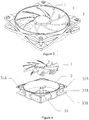
Figure 2 is a schematic view of the rubber layers of the cooling fan ofEmbodiment 1 of the present invention after the rubber layers are molded by secondary injection; -
Figure 3 is a perspective view of an assembled cooling fan ofEmbodiment 1 of the present invention; -
Figure 4 is a schematic view of an assembled cooling fan ofEmbodiment 2 of the present invention (before the rubber layers are molded by secondary injection); -
Figure 5 is a schematic view of the rubber layers of the cooling fan ofEmbodiment 2 of the present invention after the rubber layers are molded by secondary injection; -
Figure 6 is a perspective view of an assembled cooling fan ofEmbodiment 2 of the present invention; -
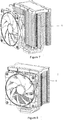
Figure 7 is a schematic view of a cooling fan of the present invention assembled with a set of cooling fins (take the cooling fan ofEmbodiment 1 as an example); -
Figure 8 is a schematic view of a cooling fan of the present invention assembled with a set of cooling fins offigure 7 (i.e., an application state view); -
Figure 9 is a schematic view showing the assembling process of a cooling fan ofEmbodiment 3 of the present invention (before the rubber layers are molded by secondary injection); -
Figure 10 is a schematic view of the rubber layers of the cooling fan ofEmbodiment 3 of the present invention after the rubber layers are molded by secondary injection; -
Figure 11 is a perspective view of an assembled cooling fan ofEmbodiment 3 of the present invention; and -
Figure 12 is a schematic view showing the assembling process of a cooling fan of the present invention with a cooling hole-plate of a computer mainframe (take the cooling fan ofEmbodiment 3 as an example). - The following reference signs are provided with reference to the above drawings:
1-fan impeller, 2-fan frame, 3-fan body, 4-rubber layer, 5-set of cooling fins for a CPU, 6-steel wire button, 7-cooling hole-plate of a computer mainframe, 8-vibration absorbing screw, 31-through hole, 32-upper part of end corner, 33-lower part of end corner, 34-supporting portion, 3A-fan body, 31A-through hole, 32A-upper part of end corner, 33A-lower part of end corner, 34A-supporting portion, 4A-rubber layer, 3B-fan body, 31B-through hole, 32B-upper part of end corner, 33B-lower part of end corner, 34B-supporting portion, 4B-rubber layer, 71-through hole of computer mainframe, 81-conical portion, 82-clipping position. - The followings will specifically describe several embodiments of this invention with reference to the drawings. However, it should be understood that the protection scope of this invention shall not be restricted by the specific embodiments. It should be noted that the cooling fan of this invention can be installed on the element that needs cooling. The followings will specifically describe an example in which the cooling fan is installed on a set of cooling fins of a CPU or a cooling hole-plate of a computer mainframe.
- As shown in
Figures 1-3 , the cooling fan of this invention, which is installed at the corresponding position of a set ofcooling fins 5 of a CPU (i.e., the outer surface thereof, seeFigures 7-8 ), includes afan body 3, afan frame 2 and afan impeller 1, wherein thefan impeller 1 is installed in thefan frame 2, thefan frame 2 is circular in shape, and thefan body 3 is arranged along the outer circumference of the fan frame. The frame of thefan body 3 is in a square shape, wherein the four sides of the square are in a three-dimensional X shape. The end corners of the X-shaped structure are divided into upper parts 32 (there are four upper parts in total) and lower parts 33 (there are four lower parts in total). The upper and lower parts of the end corners are parallel with each other. Supportingportions 34 are provided between the upper and lower parts of the end corners, the supporting portions being integrally formed with the fan body. Through holes 31 (there are 8 through holes in total) are provided in the planes of the upper and lower parts of the end corners, respectively. Arubber layer 4, which is formed by secondary injection molding, is arranged at the outer surface of thefan body 3 and the contact parts between the set of cooling fins and the upper and lower edges of the fan frame, respectively. After secondary injection molding, the upper edges of the throughholes 31 of the fan body are made level with the corresponding upper and lower edges of thefan frame 2. The circular inner wall of thefan frame 2 is made of a rubber material that is formed by primary injection molding (i.e., secondary injection molding is not performed here). - As shown in
Figures 4-6 , the cooling fan of this invention, which is installed at the corresponding position of a set ofcooling fins 5 of a CPU (i.e., the outer surface), includes afan body 3A, afan frame 2 and afan impeller 1, wherein thefan impeller 1 is installed in thefan frame 2, thefan frame 2 is circular in shape, and thefan body 3A is arranged along the outer circumference of the fan frame. The frame of thefan body 3A is in a square shape, wherein the four sides of the square are in a three-dimensional double U shape. The U-shaped openings face the end corners of the fan body and the U-shaped openings of adjacent frames converge and are connected as one piece. The end corners of the U-shaped structure are divided intoupper parts 32A (there are four upper parts in total) andlower parts 33A (there are four lower parts in total). The upper and lower parts of the end corners are parallel with each other. Supportingportions 34A are provided between the upper and lower parts of the end corners, the supporting portions being integrally formed with the fan body. Throughholes 31A (there are 8 through holes in total) are provided in the planes of the upper and lower parts of the end corners, respectively. Arubber layer 4A, which is formed by secondary injection molding, is arranged at the outer surface of thefan body 3A and the contact parts between the set of cooling fins and the upper and lower edges of the fan frame, respectively. After secondary injection molding, the upper edges of the throughholes 31A of the fan body are made level with the corresponding upper and lower edges of thefan frame 2. The circular inner wall of thefan frame 2 is made of a rubber material that is formed by primary injection molding (i.e., secondary injection molding is not performed here). - An assembled cooling fan of the above two embodiments can be applied to a set of cooling fins of a CPU or used for cooling a computer mainframe or used for other cooling elements. The followings describe the installation process of the cooling fan of
Embodiment 1 when the cooling fan is applied to a set of cooling fins of a CPU, for example. As shown inFigures 7-8 , when the cooling fan is to be installed, the hook structures at both ends of a steel wire button pass the through holes of the lower parts of the end corners of the fan body and are clipped therein, wherein a middle portion of the steel wire button is clipped at the corresponding position of the set of cooling fins. The assembled cooling fan is clipped by thesteel wire button 6 to the corresponding position of the set of cooling fins of a CPU, so that the contact parts between the cooling fan and the cooling fins are the above rubber layers made by secondary injection molding. - As shown in
Figures 9-11 . the cooling fan of this invention, which is installed at the corresponding position of a cooling hole-plate 7 of a computer mainframe, includes afan body 3B afan frame 2 and afan impeller 1, wherein thefan impeller 1 is installed in thefan frame 2, thefan frame 2 is circular in shape, and thefan body 3B is arranged along the outer circumference of the fan frame. Thebody 3B consists of four end corners disposed on the outer circumference of the fan frame at uniform intervals. The end corners are divided intoupper parts 32B (there are four upper parts in total) andlower parts 33B (there are four lower parts in total). The upper and lower parts of the end corners are parallel with each other. Supportingportions 34B are provided between the upper and lower parts of the end corners, the supporting portions being integrally formed with the fan body. Throughholes 31B (there are 8 through holes in total) are provided in the planes of the upper and lower parts of the end corners, respectively. Arubber layer 4B, which is formed by secondary injection molding, is arranged at the outer surface of thefan body 3B and the contact parts between the cooling hole-plate 7 and the upper and lower edges of the fan frame, respectively. After secondary injection molding, the upper edges of the throughholes 31B of the fan body are made level with the corresponding upper and lower edges of thefan frame 2. The circular inner wall of thefan frame 2 is made of a rubber material that is formed by primary injection molding (i.e., secondary injection molding is not performed here). - An assembled cooling fan of
Embodiment 3 is fixed by vibration absorbing screws to a cooling hole-plate of a computer mainframe. The cooling hole-plate is provided with through holes 71 (there are four such through holes in total) of the computer mainframe, which are co-axial with the corresponding through holes of the fan body. The vibration absorbing screw is provided with aconical portion 81 and aclipping position 82. When fixing the assembled cooling fan, theconical portion 81 sequentially passes the throughholes 71 of the computer mainframe, the lower through holes of the end corner of the fan body, the cooling hole-plate 7 of the computer mainframe and the lower part of the end corner, and is clipped within theclipping position 82. The vibration absorbing screws are also made of rubber so as to absorb vibration after the cooling fan is fixed to the computer mainframe. Of course, except for cooling a computer mainframe, the cooling fan ofEmbodiment 3 can also be applied to a set of cooling fins of a CPU or other cooling elements. - Since the upper and lower edges of the fan frame of the cooling fan of the present invention and the fan body, which have been processed by primary injection molding, use rubber layers formed by secondary injection molding, and the upper edges of the through holes are made level with the corresponding upper and lower edges of the fan frame, the contact parts between the cooling fan and the set of cooling fins of a CPU or a computer mainframe are rubber layers. Thus, flexible contact between the cooling fan and the cooling fins or the cooling hole-plate of a computer mainframe can be achieved, thereby effectively offsetting the longitudinal, transverse impact and vibration, reducing noise and extending the service life of the cooling fan.
- The above disclosure only covers several specific embodiments of the present invention, but the present invention is not limited thereto. Any variations of the present invention that a person skilled in the art can conceive of shall fall into the protection scope of this invention.
Claims (10)
- A cooling fan, which is installable at a corresponding position of a cooling element, comprising a fan body (3, 3A, 3B), a fan frame (2) and a fan impeller (1), wherein the fan frame (2) is circular in shape, the fan body (3, 3A, 3B) is arranged along an outer circumference of the fan frame (2), and the fan impeller (1) is installed in the fan frame (2), the cooling fan being characterized in that a rubber layer (4), which is formed by secondary injection molding, is arranged at an outer surface of the fan body (3, 3A, 3B) and at the upper and lower edges of the fan frame (2), respectively, at a place where the cooling fan contacts the cooling element when the cooling fan is installed at the corresponding position of the cooling element.
- The cooling fan according to claim 1, characterized in that the cooling element is a set of cooling fins (5) for a CPU in a computer mainframe.
- The cooling fan according to claim 1, characterized in that the cooling element is a cooling hole-plate (7) of a computer mainframe.
- The cooling fan according to any one of claims 1 to 3, characterized in that through holes (31, 31A, 31B) are provided at upper and lower parts (32, 33, 32A, 33A, 32B, 33B) of four end corners of the fan body (3, 3A, 3B), respectively, and rubber layers are also provided at the inner walls of the through holes (31, 31A, 31B), so that after secondary injection molding, the outer edges of the through holes (31, 31A, 31B) are made level with the corresponding upper and lower edges of the fan frame (2).
- The cooling fan according to claim 2, characterized in that an assembled cooling fan is fastenable by a steel wire button (6) to corresponding positions of the set of cooling fins (5), wherein the rubber layer that is formed by secondary injection molding provides contact parts between the cooling fan and the cooling fins (5).
- The cooling fan according to claim 5, characterized in that four frames of the fan body (3) are in the shape of a three-dimensional X, wherein upper and lower parts (32, 33) of the end corners are parallel with each other; through holes (31) are provided within the planes of the upper and lower parts (32, 33) of the end corners, respectively; and wherein supporting portions (34) are provided between the upper and lower parts (32A, 33A) of the end corners, the supporting portions (34A) being integrally formed with the fan body (3A).
- The cooling fan according to claim 5, characterized in that four frames of the fan body (3A) are in the shape of a three-dimensional double U, wherein U-shaped openings face the end corners of the fan body (3A) and the U-shaped openings of adjacent frames converge and are connected as one piece; upper and lower parts (32A, 32B) of the end corners are parallel with each other; through holes (31A) are provided within the planes of the upper and lower parts (32A, 33A) of the end corners, respectively; and wherein supporting portions (34A) are provided between the upper and lower parts (32A, 33A) of the end corners, the supporting portions (34A) being integrally formed with the fan body (3A).
- The cooling fan according to claim 3, characterized in that an assembled cooling fan is fastenable by vibration absorbing screws (8) to the cooling hole-plate (7) of the computer mainframe, wherein through holes (71) of the computer mainframe are provided on the cooling hole-plate (7) and are co-axial with corresponding through holes (31B) of the fan body (3B); the vibration absorbing screws (8) are provided with a conical portion (81) and a clipping position (82); and wherein when fixing the assembled cooling fan, the conical portion (81) sequentially passes the mainframe through holes (71), the lower through holes (31B) of the end corner of the fan body (3B), the cooling hole-plate (7) of the computer mainframe and a lower part (33B) of the end corner, and is clipped within the clipping position (82).
- The cooling fan according to claim 8, characterized in that the vibration absorbing screw (8) is made of rubber.
- The cooling fan according to claim 8 or 9, characterized in that the fan body (3B) consists of four end corners disposed on the outer circumference of the fan frame (2) at uniform intervals, wherein the upper and lower parts (31B, 33B) of the end corners are parallel with each other; the through holes (31B) of the fan body (3B) are provided within the planes of the upper and lower parts (32B, 33B) of the end corners, respectively; and wherein supporting portions (34B) are provided between the upper and lower parts (32B, 33B) of the end corners, the supporting portions (34B) being integrally formed with the fan body (3B).
Applications Claiming Priority (2)
| Application Number | Priority Date | Filing Date | Title |
|---|---|---|---|
| CN200920278237 | 2009-12-21 | ||
| PCT/CN2010/070710 WO2011075963A1 (en) | 2009-12-21 | 2010-02-23 | Heat radiation fan |
Publications (3)
| Publication Number | Publication Date |
|---|---|
| EP2518327A1 EP2518327A1 (en) | 2012-10-31 |
| EP2518327A4 EP2518327A4 (en) | 2017-08-02 |
| EP2518327B1 true EP2518327B1 (en) | 2019-08-14 |
Family
ID=43116027
Family Applications (1)
| Application Number | Title | Priority Date | Filing Date |
|---|---|---|---|
| EP10838529.5A Active EP2518327B1 (en) | 2009-12-21 | 2010-02-23 | Heat radiation fan |
Country Status (3)
| Country | Link |
|---|---|
| EP (1) | EP2518327B1 (en) |
| CN (2) | CN201650793U (en) |
| WO (1) | WO2011075963A1 (en) |
Families Citing this family (2)
| Publication number | Priority date | Publication date | Assignee | Title |
|---|---|---|---|---|
| CN201650793U (en) * | 2009-12-21 | 2010-11-24 | 北京市九州风神科贸有限责任公司 | Cooling fan |
| CN105411431A (en) * | 2015-08-07 | 2016-03-23 | 九阳股份有限公司 | A low-noise cooking machine |
Family Cites Families (18)
| Publication number | Priority date | Publication date | Assignee | Title |
|---|---|---|---|---|
| US4807718A (en) * | 1987-03-18 | 1989-02-28 | Digital Equipment Corporation | Acoustic noise control for fans |
| CN2358381Y (en) * | 1998-11-30 | 2000-01-12 | 宏桦国际股份有限公司 | Combined device of fan and radiating fin |
| CN2492876Y (en) * | 2001-06-06 | 2002-05-22 | 新富国际股份有限公司 | Auxiliary positioning device for cooling fan |
| US20040010351A1 (en) * | 2002-07-12 | 2004-01-15 | Ahmed Mohiuddin | Method and system for information handling system component mounting with vibration dampening |
| CN2720777Y (en) * | 2004-06-21 | 2005-08-24 | 鸿富锦精密工业(深圳)有限公司 | Radiating device |
| DE102004034472A1 (en) * | 2004-07-15 | 2006-02-09 | Spiess, Heike | Steamed fan |
| US7168920B2 (en) * | 2004-09-13 | 2007-01-30 | Asia Vital Component Co., Ltd. | Fan base case |
| US20070154300A1 (en) * | 2005-12-30 | 2007-07-05 | Chien-Fa Liang | Fan vibration absorber device |
| US7488152B2 (en) * | 2006-04-10 | 2009-02-10 | Super Micro Computer, Inc. | Vibration absorption device for a fan |
| CN100404237C (en) * | 2006-04-14 | 2008-07-23 | 上海华特汽车配件有限公司 | Making process of car body cavity vibration isolating pad |
| CN200969732Y (en) * | 2006-11-16 | 2007-10-31 | 鈤新科技股份有限公司 | Heat sink with shock-absorbing mechanism |
| TW200903230A (en) * | 2007-07-10 | 2009-01-16 | Delta Electronics Inc | Fan and frame thereof |
| US7639497B2 (en) * | 2007-12-10 | 2009-12-29 | Hong Fu Jin Precision Industry (Shenzhen) Co., Ltd. | Heat dissipation device having a fan mounted thereon |
| CN201178543Y (en) * | 2008-04-03 | 2009-01-07 | 鈤新科技股份有限公司 | Heat sink with shock-absorbing structure |
| TWM355412U (en) * | 2008-12-19 | 2009-04-21 | Enermax Technology Corp | Shockproof fan device |
| CN201335041Y (en) * | 2009-01-23 | 2009-10-28 | 政久兴业股份有限公司 | Fan shockproof structure |
| DE202009003591U1 (en) * | 2009-03-13 | 2009-07-09 | Dynaeon Industrial Co., Ltd. | Vibration-proof fan construction |
| CN201650793U (en) * | 2009-12-21 | 2010-11-24 | 北京市九州风神科贸有限责任公司 | Cooling fan |
-
2010
- 2010-01-12 CN CN201020002133XU patent/CN201650793U/en not_active Expired - Lifetime
- 2010-01-12 CN CN201010002245.XA patent/CN102102678B/en active Active
- 2010-02-23 EP EP10838529.5A patent/EP2518327B1/en active Active
- 2010-02-23 WO PCT/CN2010/070710 patent/WO2011075963A1/en not_active Ceased
Non-Patent Citations (1)
| Title |
|---|
| None * |
Also Published As
| Publication number | Publication date |
|---|---|
| CN201650793U (en) | 2010-11-24 |
| CN102102678A (en) | 2011-06-22 |
| WO2011075963A1 (en) | 2011-06-30 |
| EP2518327A1 (en) | 2012-10-31 |
| CN102102678B (en) | 2014-09-17 |
| EP2518327A4 (en) | 2017-08-02 |
Similar Documents
| Publication | Publication Date | Title |
|---|---|---|
| US20120257965A1 (en) | Cooling fan | |
| US7684187B1 (en) | Heat dissipation device | |
| US9157442B2 (en) | Fan with integrated vibration absorbing structure | |
| US8043049B2 (en) | Air fan damping structure | |
| US20110158791A1 (en) | Fan assembly with vibration absorbing member | |
| US7385813B2 (en) | Assembly structure for securing heat-dissipating fan | |
| US8388305B2 (en) | Fan assembly with vibration absorbing member | |
| US8608438B2 (en) | Mounting device for fan and fan module with the same | |
| US20130170995A1 (en) | Axial flow fan blade structure and axial flow fan thereof | |
| US20120195738A1 (en) | Shockproof fan apparatus | |
| US20100129235A1 (en) | Anti-vibration structure for cooling fan | |
| US7061155B1 (en) | Rotor device capable of dissipating heat and resisting foreign objects | |
| US9222479B2 (en) | Fan and fan frame thereof | |
| US20120114477A1 (en) | Case structure and fan frame fixing module | |
| EP2518327A1 (en) | Heat radiation fan | |
| CN101398708B (en) | fixed components | |
| JP2010267751A (en) | Mounting structure of ventilation fan for electrical equipment storage box | |
| CN107943243A (en) | A kind of mute, heat dissipation, reinforcing server easy to install | |
| JP3148042U (en) | Anti-vibration structure for electronic equipment cooling fan | |
| US10334754B2 (en) | Heat dissipation device | |
| CN2627262Y (en) | The shock-absorbing combination device of cooling fan and substrate | |
| US8508942B2 (en) | Electronic device with heat dissipation structure | |
| CN204755410U (en) | Vibration-absorbing structure of the cooling fan | |
| JP2010283254A (en) | Fan unit holding member | |
| US8830681B2 (en) | Electronic device with heat dissipation apparatus |
Legal Events
| Date | Code | Title | Description |
|---|---|---|---|
| PUAI | Public reference made under article 153(3) epc to a published international application that has entered the european phase |
Free format text: ORIGINAL CODE: 0009012 |
|
| 17P | Request for examination filed |
Effective date: 20120620 |
|
| AK | Designated contracting states |
Kind code of ref document: A1 Designated state(s): AT BE BG CH CY CZ DE DK EE ES FI FR GB GR HR HU IE IS IT LI LT LU LV MC MK MT NL NO PL PT RO SE SI SK SM TR |
|
| DAX | Request for extension of the european patent (deleted) | ||
| RA4 | Supplementary search report drawn up and despatched (corrected) |
Effective date: 20170704 |
|
| RIC1 | Information provided on ipc code assigned before grant |
Ipc: F04D 29/66 20060101AFI20170628BHEP |
|
| GRAP | Despatch of communication of intention to grant a patent |
Free format text: ORIGINAL CODE: EPIDOSNIGR1 |
|
| STAA | Information on the status of an ep patent application or granted ep patent |
Free format text: STATUS: GRANT OF PATENT IS INTENDED |
|
| INTG | Intention to grant announced |
Effective date: 20190305 |
|
| GRAS | Grant fee paid |
Free format text: ORIGINAL CODE: EPIDOSNIGR3 |
|
| GRAA | (expected) grant |
Free format text: ORIGINAL CODE: 0009210 |
|
| STAA | Information on the status of an ep patent application or granted ep patent |
Free format text: STATUS: THE PATENT HAS BEEN GRANTED |
|
| AK | Designated contracting states |
Kind code of ref document: B1 Designated state(s): AT BE BG CH CY CZ DE DK EE ES FI FR GB GR HR HU IE IS IT LI LT LU LV MC MK MT NL NO PL PT RO SE SI SK SM TR |
|
| REG | Reference to a national code |
Ref country code: GB Ref legal event code: FG4D |
|
| REG | Reference to a national code |
Ref country code: CH Ref legal event code: EP Ref country code: AT Ref legal event code: REF Ref document number: 1167357 Country of ref document: AT Kind code of ref document: T Effective date: 20190815 |
|
| REG | Reference to a national code |
Ref country code: DE Ref legal event code: R096 Ref document number: 602010060596 Country of ref document: DE |
|
| REG | Reference to a national code |
Ref country code: IE Ref legal event code: FG4D |
|
| REG | Reference to a national code |
Ref country code: NL Ref legal event code: MP Effective date: 20190814 |
|
| REG | Reference to a national code |
Ref country code: LT Ref legal event code: MG4D |
|
| PG25 | Lapsed in a contracting state [announced via postgrant information from national office to epo] |
Ref country code: BG Free format text: LAPSE BECAUSE OF FAILURE TO SUBMIT A TRANSLATION OF THE DESCRIPTION OR TO PAY THE FEE WITHIN THE PRESCRIBED TIME-LIMIT Effective date: 20191114 Ref country code: NO Free format text: LAPSE BECAUSE OF FAILURE TO SUBMIT A TRANSLATION OF THE DESCRIPTION OR TO PAY THE FEE WITHIN THE PRESCRIBED TIME-LIMIT Effective date: 20191114 Ref country code: HR Free format text: LAPSE BECAUSE OF FAILURE TO SUBMIT A TRANSLATION OF THE DESCRIPTION OR TO PAY THE FEE WITHIN THE PRESCRIBED TIME-LIMIT Effective date: 20190814 Ref country code: PT Free format text: LAPSE BECAUSE OF FAILURE TO SUBMIT A TRANSLATION OF THE DESCRIPTION OR TO PAY THE FEE WITHIN THE PRESCRIBED TIME-LIMIT Effective date: 20191216 Ref country code: SE Free format text: LAPSE BECAUSE OF FAILURE TO SUBMIT A TRANSLATION OF THE DESCRIPTION OR TO PAY THE FEE WITHIN THE PRESCRIBED TIME-LIMIT Effective date: 20190814 Ref country code: FI Free format text: LAPSE BECAUSE OF FAILURE TO SUBMIT A TRANSLATION OF THE DESCRIPTION OR TO PAY THE FEE WITHIN THE PRESCRIBED TIME-LIMIT Effective date: 20190814 Ref country code: LT Free format text: LAPSE BECAUSE OF FAILURE TO SUBMIT A TRANSLATION OF THE DESCRIPTION OR TO PAY THE FEE WITHIN THE PRESCRIBED TIME-LIMIT Effective date: 20190814 Ref country code: NL Free format text: LAPSE BECAUSE OF FAILURE TO SUBMIT A TRANSLATION OF THE DESCRIPTION OR TO PAY THE FEE WITHIN THE PRESCRIBED TIME-LIMIT Effective date: 20190814 |
|
| REG | Reference to a national code |
Ref country code: AT Ref legal event code: MK05 Ref document number: 1167357 Country of ref document: AT Kind code of ref document: T Effective date: 20190814 |
|
| PG25 | Lapsed in a contracting state [announced via postgrant information from national office to epo] |
Ref country code: ES Free format text: LAPSE BECAUSE OF FAILURE TO SUBMIT A TRANSLATION OF THE DESCRIPTION OR TO PAY THE FEE WITHIN THE PRESCRIBED TIME-LIMIT Effective date: 20190814 Ref country code: LV Free format text: LAPSE BECAUSE OF FAILURE TO SUBMIT A TRANSLATION OF THE DESCRIPTION OR TO PAY THE FEE WITHIN THE PRESCRIBED TIME-LIMIT Effective date: 20190814 Ref country code: IS Free format text: LAPSE BECAUSE OF FAILURE TO SUBMIT A TRANSLATION OF THE DESCRIPTION OR TO PAY THE FEE WITHIN THE PRESCRIBED TIME-LIMIT Effective date: 20191214 Ref country code: GR Free format text: LAPSE BECAUSE OF FAILURE TO SUBMIT A TRANSLATION OF THE DESCRIPTION OR TO PAY THE FEE WITHIN THE PRESCRIBED TIME-LIMIT Effective date: 20191115 |
|
| PG25 | Lapsed in a contracting state [announced via postgrant information from national office to epo] |
Ref country code: TR Free format text: LAPSE BECAUSE OF FAILURE TO SUBMIT A TRANSLATION OF THE DESCRIPTION OR TO PAY THE FEE WITHIN THE PRESCRIBED TIME-LIMIT Effective date: 20190814 |
|
| PG25 | Lapsed in a contracting state [announced via postgrant information from national office to epo] |
Ref country code: RO Free format text: LAPSE BECAUSE OF FAILURE TO SUBMIT A TRANSLATION OF THE DESCRIPTION OR TO PAY THE FEE WITHIN THE PRESCRIBED TIME-LIMIT Effective date: 20190814 Ref country code: PL Free format text: LAPSE BECAUSE OF FAILURE TO SUBMIT A TRANSLATION OF THE DESCRIPTION OR TO PAY THE FEE WITHIN THE PRESCRIBED TIME-LIMIT Effective date: 20190814 Ref country code: EE Free format text: LAPSE BECAUSE OF FAILURE TO SUBMIT A TRANSLATION OF THE DESCRIPTION OR TO PAY THE FEE WITHIN THE PRESCRIBED TIME-LIMIT Effective date: 20190814 Ref country code: AT Free format text: LAPSE BECAUSE OF FAILURE TO SUBMIT A TRANSLATION OF THE DESCRIPTION OR TO PAY THE FEE WITHIN THE PRESCRIBED TIME-LIMIT Effective date: 20190814 Ref country code: IT Free format text: LAPSE BECAUSE OF FAILURE TO SUBMIT A TRANSLATION OF THE DESCRIPTION OR TO PAY THE FEE WITHIN THE PRESCRIBED TIME-LIMIT Effective date: 20190814 Ref country code: DK Free format text: LAPSE BECAUSE OF FAILURE TO SUBMIT A TRANSLATION OF THE DESCRIPTION OR TO PAY THE FEE WITHIN THE PRESCRIBED TIME-LIMIT Effective date: 20190814 |
|
| PG25 | Lapsed in a contracting state [announced via postgrant information from national office to epo] |
Ref country code: SM Free format text: LAPSE BECAUSE OF FAILURE TO SUBMIT A TRANSLATION OF THE DESCRIPTION OR TO PAY THE FEE WITHIN THE PRESCRIBED TIME-LIMIT Effective date: 20190814 Ref country code: IS Free format text: LAPSE BECAUSE OF FAILURE TO SUBMIT A TRANSLATION OF THE DESCRIPTION OR TO PAY THE FEE WITHIN THE PRESCRIBED TIME-LIMIT Effective date: 20200224 Ref country code: SK Free format text: LAPSE BECAUSE OF FAILURE TO SUBMIT A TRANSLATION OF THE DESCRIPTION OR TO PAY THE FEE WITHIN THE PRESCRIBED TIME-LIMIT Effective date: 20190814 Ref country code: CZ Free format text: LAPSE BECAUSE OF FAILURE TO SUBMIT A TRANSLATION OF THE DESCRIPTION OR TO PAY THE FEE WITHIN THE PRESCRIBED TIME-LIMIT Effective date: 20190814 |
|
| REG | Reference to a national code |
Ref country code: DE Ref legal event code: R097 Ref document number: 602010060596 Country of ref document: DE |
|
| PLBE | No opposition filed within time limit |
Free format text: ORIGINAL CODE: 0009261 |
|
| STAA | Information on the status of an ep patent application or granted ep patent |
Free format text: STATUS: NO OPPOSITION FILED WITHIN TIME LIMIT |
|
| PG2D | Information on lapse in contracting state deleted |
Ref country code: IS |
|
| 26N | No opposition filed |
Effective date: 20200603 |
|
| PG25 | Lapsed in a contracting state [announced via postgrant information from national office to epo] |
Ref country code: SI Free format text: LAPSE BECAUSE OF FAILURE TO SUBMIT A TRANSLATION OF THE DESCRIPTION OR TO PAY THE FEE WITHIN THE PRESCRIBED TIME-LIMIT Effective date: 20190814 |
|
| REG | Reference to a national code |
Ref country code: DE Ref legal event code: R119 Ref document number: 602010060596 Country of ref document: DE |
|
| REG | Reference to a national code |
Ref country code: CH Ref legal event code: PL |
|
| GBPC | Gb: european patent ceased through non-payment of renewal fee |
Effective date: 20200223 |
|
| REG | Reference to a national code |
Ref country code: BE Ref legal event code: MM Effective date: 20200229 |
|
| PG25 | Lapsed in a contracting state [announced via postgrant information from national office to epo] |
Ref country code: LU Free format text: LAPSE BECAUSE OF NON-PAYMENT OF DUE FEES Effective date: 20200223 Ref country code: MC Free format text: LAPSE BECAUSE OF FAILURE TO SUBMIT A TRANSLATION OF THE DESCRIPTION OR TO PAY THE FEE WITHIN THE PRESCRIBED TIME-LIMIT Effective date: 20190814 |
|
| PG25 | Lapsed in a contracting state [announced via postgrant information from national office to epo] |
Ref country code: CH Free format text: LAPSE BECAUSE OF NON-PAYMENT OF DUE FEES Effective date: 20200229 Ref country code: LI Free format text: LAPSE BECAUSE OF NON-PAYMENT OF DUE FEES Effective date: 20200229 |
|
| PG25 | Lapsed in a contracting state [announced via postgrant information from national office to epo] |
Ref country code: IE Free format text: LAPSE BECAUSE OF NON-PAYMENT OF DUE FEES Effective date: 20200223 Ref country code: DE Free format text: LAPSE BECAUSE OF NON-PAYMENT OF DUE FEES Effective date: 20200901 Ref country code: FR Free format text: LAPSE BECAUSE OF NON-PAYMENT OF DUE FEES Effective date: 20200229 Ref country code: GB Free format text: LAPSE BECAUSE OF NON-PAYMENT OF DUE FEES Effective date: 20200223 |
|
| PG25 | Lapsed in a contracting state [announced via postgrant information from national office to epo] |
Ref country code: BE Free format text: LAPSE BECAUSE OF NON-PAYMENT OF DUE FEES Effective date: 20200229 |
|
| PG25 | Lapsed in a contracting state [announced via postgrant information from national office to epo] |
Ref country code: MT Free format text: LAPSE BECAUSE OF FAILURE TO SUBMIT A TRANSLATION OF THE DESCRIPTION OR TO PAY THE FEE WITHIN THE PRESCRIBED TIME-LIMIT Effective date: 20190814 Ref country code: CY Free format text: LAPSE BECAUSE OF FAILURE TO SUBMIT A TRANSLATION OF THE DESCRIPTION OR TO PAY THE FEE WITHIN THE PRESCRIBED TIME-LIMIT Effective date: 20190814 |
|
| PG25 | Lapsed in a contracting state [announced via postgrant information from national office to epo] |
Ref country code: MK Free format text: LAPSE BECAUSE OF FAILURE TO SUBMIT A TRANSLATION OF THE DESCRIPTION OR TO PAY THE FEE WITHIN THE PRESCRIBED TIME-LIMIT Effective date: 20190814 |