EP2518287A1 - Exhaust purification device - Google Patents
Exhaust purification device Download PDFInfo
- Publication number
- EP2518287A1 EP2518287A1 EP10838942A EP10838942A EP2518287A1 EP 2518287 A1 EP2518287 A1 EP 2518287A1 EP 10838942 A EP10838942 A EP 10838942A EP 10838942 A EP10838942 A EP 10838942A EP 2518287 A1 EP2518287 A1 EP 2518287A1
- Authority
- EP
- European Patent Office
- Prior art keywords
- urea water
- exhaust gas
- mixing pipe
- opening sections
- particulate filter
- Prior art date
- Legal status (The legal status is an assumption and is not a legal conclusion. Google has not performed a legal analysis and makes no representation as to the accuracy of the status listed.)
- Granted
Links
Images

Classifications
-
- F—MECHANICAL ENGINEERING; LIGHTING; HEATING; WEAPONS; BLASTING
- F01—MACHINES OR ENGINES IN GENERAL; ENGINE PLANTS IN GENERAL; STEAM ENGINES
- F01N—GAS-FLOW SILENCERS OR EXHAUST APPARATUS FOR MACHINES OR ENGINES IN GENERAL; GAS-FLOW SILENCERS OR EXHAUST APPARATUS FOR INTERNAL-COMBUSTION ENGINES
- F01N3/00—Exhaust or silencing apparatus having means for purifying, rendering innocuous, or otherwise treating exhaust
- F01N3/08—Exhaust or silencing apparatus having means for purifying, rendering innocuous, or otherwise treating exhaust for rendering innocuous
- F01N3/10—Exhaust or silencing apparatus having means for purifying, rendering innocuous, or otherwise treating exhaust for rendering innocuous by thermal or catalytic conversion of noxious components of exhaust
- F01N3/18—Exhaust or silencing apparatus having means for purifying, rendering innocuous, or otherwise treating exhaust for rendering innocuous by thermal or catalytic conversion of noxious components of exhaust characterised by methods of operation; Control
- F01N3/20—Exhaust or silencing apparatus having means for purifying, rendering innocuous, or otherwise treating exhaust for rendering innocuous by thermal or catalytic conversion of noxious components of exhaust characterised by methods of operation; Control specially adapted for catalytic conversion
- F01N3/206—Adding periodically or continuously substances to exhaust gases for promoting purification, e.g. catalytic material in liquid form, NOx reducing agents
- F01N3/2066—Selective catalytic reduction [SCR]
-
- B—PERFORMING OPERATIONS; TRANSPORTING
- B01—PHYSICAL OR CHEMICAL PROCESSES OR APPARATUS IN GENERAL
- B01D—SEPARATION
- B01D53/00—Separation of gases or vapours; Recovering vapours of volatile solvents from gases; Chemical or biological purification of waste gases, e.g. engine exhaust gases, smoke, fumes, flue gases, aerosols
- B01D53/34—Chemical or biological purification of waste gases
- B01D53/92—Chemical or biological purification of waste gases of engine exhaust gases
- B01D53/94—Chemical or biological purification of waste gases of engine exhaust gases by catalytic processes
- B01D53/9404—Removing only nitrogen compounds
- B01D53/9409—Nitrogen oxides
- B01D53/9431—Processes characterised by a specific device
-
- B—PERFORMING OPERATIONS; TRANSPORTING
- B01—PHYSICAL OR CHEMICAL PROCESSES OR APPARATUS IN GENERAL
- B01D—SEPARATION
- B01D53/00—Separation of gases or vapours; Recovering vapours of volatile solvents from gases; Chemical or biological purification of waste gases, e.g. engine exhaust gases, smoke, fumes, flue gases, aerosols
- B01D53/34—Chemical or biological purification of waste gases
- B01D53/92—Chemical or biological purification of waste gases of engine exhaust gases
- B01D53/94—Chemical or biological purification of waste gases of engine exhaust gases by catalytic processes
- B01D53/9459—Removing one or more of nitrogen oxides, carbon monoxide, or hydrocarbons by multiple successive catalytic functions; systems with more than one different function, e.g. zone coated catalysts
- B01D53/9477—Removing one or more of nitrogen oxides, carbon monoxide, or hydrocarbons by multiple successive catalytic functions; systems with more than one different function, e.g. zone coated catalysts with catalysts positioned on separate bricks, e.g. exhaust systems
-
- F—MECHANICAL ENGINEERING; LIGHTING; HEATING; WEAPONS; BLASTING
- F01—MACHINES OR ENGINES IN GENERAL; ENGINE PLANTS IN GENERAL; STEAM ENGINES
- F01N—GAS-FLOW SILENCERS OR EXHAUST APPARATUS FOR MACHINES OR ENGINES IN GENERAL; GAS-FLOW SILENCERS OR EXHAUST APPARATUS FOR INTERNAL-COMBUSTION ENGINES
- F01N13/00—Exhaust or silencing apparatus characterised by constructional features
- F01N13/009—Exhaust or silencing apparatus characterised by constructional features having two or more separate purifying devices arranged in series
-
- F—MECHANICAL ENGINEERING; LIGHTING; HEATING; WEAPONS; BLASTING
- F01—MACHINES OR ENGINES IN GENERAL; ENGINE PLANTS IN GENERAL; STEAM ENGINES
- F01N—GAS-FLOW SILENCERS OR EXHAUST APPARATUS FOR MACHINES OR ENGINES IN GENERAL; GAS-FLOW SILENCERS OR EXHAUST APPARATUS FOR INTERNAL-COMBUSTION ENGINES
- F01N13/00—Exhaust or silencing apparatus characterised by constructional features
- F01N13/009—Exhaust or silencing apparatus characterised by constructional features having two or more separate purifying devices arranged in series
- F01N13/0097—Exhaust or silencing apparatus characterised by constructional features having two or more separate purifying devices arranged in series the purifying devices are arranged in a single housing
-
- F—MECHANICAL ENGINEERING; LIGHTING; HEATING; WEAPONS; BLASTING
- F01—MACHINES OR ENGINES IN GENERAL; ENGINE PLANTS IN GENERAL; STEAM ENGINES
- F01N—GAS-FLOW SILENCERS OR EXHAUST APPARATUS FOR MACHINES OR ENGINES IN GENERAL; GAS-FLOW SILENCERS OR EXHAUST APPARATUS FOR INTERNAL-COMBUSTION ENGINES
- F01N13/00—Exhaust or silencing apparatus characterised by constructional features
- F01N13/02—Exhaust or silencing apparatus characterised by constructional features having two or more separate silencers in series
-
- F—MECHANICAL ENGINEERING; LIGHTING; HEATING; WEAPONS; BLASTING
- F01—MACHINES OR ENGINES IN GENERAL; ENGINE PLANTS IN GENERAL; STEAM ENGINES
- F01N—GAS-FLOW SILENCERS OR EXHAUST APPARATUS FOR MACHINES OR ENGINES IN GENERAL; GAS-FLOW SILENCERS OR EXHAUST APPARATUS FOR INTERNAL-COMBUSTION ENGINES
- F01N13/00—Exhaust or silencing apparatus characterised by constructional features
- F01N13/14—Exhaust or silencing apparatus characterised by constructional features having thermal insulation
- F01N13/141—Double-walled exhaust pipes or housings
-
- F—MECHANICAL ENGINEERING; LIGHTING; HEATING; WEAPONS; BLASTING
- F01—MACHINES OR ENGINES IN GENERAL; ENGINE PLANTS IN GENERAL; STEAM ENGINES
- F01N—GAS-FLOW SILENCERS OR EXHAUST APPARATUS FOR MACHINES OR ENGINES IN GENERAL; GAS-FLOW SILENCERS OR EXHAUST APPARATUS FOR INTERNAL-COMBUSTION ENGINES
- F01N3/00—Exhaust or silencing apparatus having means for purifying, rendering innocuous, or otherwise treating exhaust
- F01N3/08—Exhaust or silencing apparatus having means for purifying, rendering innocuous, or otherwise treating exhaust for rendering innocuous
- F01N3/10—Exhaust or silencing apparatus having means for purifying, rendering innocuous, or otherwise treating exhaust for rendering innocuous by thermal or catalytic conversion of noxious components of exhaust
- F01N3/24—Exhaust or silencing apparatus having means for purifying, rendering innocuous, or otherwise treating exhaust for rendering innocuous by thermal or catalytic conversion of noxious components of exhaust characterised by constructional aspects of converting apparatus
- F01N3/28—Construction of catalytic reactors
-
- F—MECHANICAL ENGINEERING; LIGHTING; HEATING; WEAPONS; BLASTING
- F01—MACHINES OR ENGINES IN GENERAL; ENGINE PLANTS IN GENERAL; STEAM ENGINES
- F01N—GAS-FLOW SILENCERS OR EXHAUST APPARATUS FOR MACHINES OR ENGINES IN GENERAL; GAS-FLOW SILENCERS OR EXHAUST APPARATUS FOR INTERNAL-COMBUSTION ENGINES
- F01N3/00—Exhaust or silencing apparatus having means for purifying, rendering innocuous, or otherwise treating exhaust
- F01N3/08—Exhaust or silencing apparatus having means for purifying, rendering innocuous, or otherwise treating exhaust for rendering innocuous
- F01N3/10—Exhaust or silencing apparatus having means for purifying, rendering innocuous, or otherwise treating exhaust for rendering innocuous by thermal or catalytic conversion of noxious components of exhaust
- F01N3/24—Exhaust or silencing apparatus having means for purifying, rendering innocuous, or otherwise treating exhaust for rendering innocuous by thermal or catalytic conversion of noxious components of exhaust characterised by constructional aspects of converting apparatus
- F01N3/28—Construction of catalytic reactors
- F01N3/2892—Exhaust flow directors or the like, e.g. upstream of catalytic device
-
- B—PERFORMING OPERATIONS; TRANSPORTING
- B01—PHYSICAL OR CHEMICAL PROCESSES OR APPARATUS IN GENERAL
- B01D—SEPARATION
- B01D2251/00—Reactants
- B01D2251/20—Reductants
- B01D2251/206—Ammonium compounds
- B01D2251/2067—Urea
-
- F—MECHANICAL ENGINEERING; LIGHTING; HEATING; WEAPONS; BLASTING
- F01—MACHINES OR ENGINES IN GENERAL; ENGINE PLANTS IN GENERAL; STEAM ENGINES
- F01N—GAS-FLOW SILENCERS OR EXHAUST APPARATUS FOR MACHINES OR ENGINES IN GENERAL; GAS-FLOW SILENCERS OR EXHAUST APPARATUS FOR INTERNAL-COMBUSTION ENGINES
- F01N2240/00—Combination or association of two or more different exhaust treating devices, or of at least one such device with an auxiliary device, not covered by indexing codes F01N2230/00 or F01N2250/00, one of the devices being
- F01N2240/20—Combination or association of two or more different exhaust treating devices, or of at least one such device with an auxiliary device, not covered by indexing codes F01N2230/00 or F01N2250/00, one of the devices being a flow director or deflector
-
- F—MECHANICAL ENGINEERING; LIGHTING; HEATING; WEAPONS; BLASTING
- F01—MACHINES OR ENGINES IN GENERAL; ENGINE PLANTS IN GENERAL; STEAM ENGINES
- F01N—GAS-FLOW SILENCERS OR EXHAUST APPARATUS FOR MACHINES OR ENGINES IN GENERAL; GAS-FLOW SILENCERS OR EXHAUST APPARATUS FOR INTERNAL-COMBUSTION ENGINES
- F01N2470/00—Structure or shape of exhaust gas passages, pipes or tubes
-
- F—MECHANICAL ENGINEERING; LIGHTING; HEATING; WEAPONS; BLASTING
- F01—MACHINES OR ENGINES IN GENERAL; ENGINE PLANTS IN GENERAL; STEAM ENGINES
- F01N—GAS-FLOW SILENCERS OR EXHAUST APPARATUS FOR MACHINES OR ENGINES IN GENERAL; GAS-FLOW SILENCERS OR EXHAUST APPARATUS FOR INTERNAL-COMBUSTION ENGINES
- F01N2490/00—Structure, disposition or shape of gas-chambers
-
- F—MECHANICAL ENGINEERING; LIGHTING; HEATING; WEAPONS; BLASTING
- F01—MACHINES OR ENGINES IN GENERAL; ENGINE PLANTS IN GENERAL; STEAM ENGINES
- F01N—GAS-FLOW SILENCERS OR EXHAUST APPARATUS FOR MACHINES OR ENGINES IN GENERAL; GAS-FLOW SILENCERS OR EXHAUST APPARATUS FOR INTERNAL-COMBUSTION ENGINES
- F01N2610/00—Adding substances to exhaust gases
- F01N2610/02—Adding substances to exhaust gases the substance being ammonia or urea
-
- F—MECHANICAL ENGINEERING; LIGHTING; HEATING; WEAPONS; BLASTING
- F01—MACHINES OR ENGINES IN GENERAL; ENGINE PLANTS IN GENERAL; STEAM ENGINES
- F01N—GAS-FLOW SILENCERS OR EXHAUST APPARATUS FOR MACHINES OR ENGINES IN GENERAL; GAS-FLOW SILENCERS OR EXHAUST APPARATUS FOR INTERNAL-COMBUSTION ENGINES
- F01N2610/00—Adding substances to exhaust gases
- F01N2610/14—Arrangements for the supply of substances, e.g. conduits
- F01N2610/1453—Sprayers or atomisers; Arrangement thereof in the exhaust apparatus
-
- Y—GENERAL TAGGING OF NEW TECHNOLOGICAL DEVELOPMENTS; GENERAL TAGGING OF CROSS-SECTIONAL TECHNOLOGIES SPANNING OVER SEVERAL SECTIONS OF THE IPC; TECHNICAL SUBJECTS COVERED BY FORMER USPC CROSS-REFERENCE ART COLLECTIONS [XRACs] AND DIGESTS
- Y02—TECHNOLOGIES OR APPLICATIONS FOR MITIGATION OR ADAPTATION AGAINST CLIMATE CHANGE
- Y02T—CLIMATE CHANGE MITIGATION TECHNOLOGIES RELATED TO TRANSPORTATION
- Y02T10/00—Road transport of goods or passengers
- Y02T10/10—Internal combustion engine [ICE] based vehicles
- Y02T10/12—Improving ICE efficiencies
Definitions
- the present invention relates to an exhaust emission control device.
- a particulate filter in an exhaust pipe for collection of particulates in an exhaust gas, a selective reduction catalyst capable of selectively reacting NO x with ammonia even in the presence of oxygen being arranged downstream of the particulate filter, a urea water as a reducing agent being added between the selective reduction catalyst and the particulate filter, thereby achieving simultaneous reduction of the particulates and NO x .
- the addition of the urea water to the selective reduction catalyst takes place between the particulate filter and the selective reduction catalyst; thus, in order to secure a sufficient reaction time for thermal decomposition of the added urea water into ammonia and carbon dioxide gas, it is necessary to lengthen a distance from an added position of the urea water to the selective reduction catalyst.
- the spaced-apart arrangement of the particulate filter and the selective reduction catalyst with a sufficient distance in between would significantly impair a mountability on a vehicle.
- an exhaust emission control device as shown in Fig. 1 comprising a particulate filter 3 for capture of particulates in exhaust gas 1 from an engine and a selective reduction catalyst 4 downstream of the particulate filter 3 and having a property capable of selectively reacting NO x with ammonia even in the presence of oxygen;
- the particulate filter 3 and the selective reduction catalyst 4 are encased by casings 5 and 6, respectively, and incorporated in parallel with each other in an exhaust pipe 2 through which the exhaust gas 1 from the engine flows; and an exit end of the particulate filter 3 is connected with an entry end of the selective reduction catalyst 4 through an S-shaped communication passage 7 so that the exhaust gas 1 discharged from the exit end of the particulate filter 3 is turned back in an opposite direction and is guided to the entry end of the adjacent selective reduction catalyst 4.
- the communication passage 7 is the S-shaped structure comprising a gas gathering chamber 7A encompassing the exit end of the particulate filter 3 to gather the exhaust gas 1 just discharged from the exit end through substantially perpendicular turnabout, a mixing pipe 7B for extraction of the gathered exhaust gas 1 in the chamber 7A in a direction opposite to that of the exhaust gas flow in the particulate filter 3 and a gas dispersing chamber 7C for dispersion of the exhaust gas 1 from the mixing pipe 7B through substantially perpendicular turnabout and for encompassing of the entry end of the selective reduction catalyst 4 to guide the dispersed exhaust gas 1 to the entry end of the catalyst.
- the entry end of the mixing pipe 7B is centrally provided with a urea water adding injector 8 (urea water adding means) for addition of the urea water into the mixing pipe 78 and directed to the exit end of the mixing pipe 7B.
- an oxidation catalyst 9 is installed inside the casing 5 before the particulate filter 3 to perform an oxidation treatment of unburned fuel in the exhaust gas 1.
- An ammonia reducing catalyst 10 is installed inside the casing 6 after the selective reduction catalyst 4 to perform an oxidation treatment of surplus ammonia.
- the particulates in the exhaust gas 1 are captured by the particulate filter 3; and, downstream thereof, the urea water is added in the exhaust gas 1 midway of the mixing pipe 7B by the urea water adding injector 8 and is thermally decomposed into ammonia and carbon dioxide; then, on the selective reduction catalyst 4, NO x in the exhaust gas 1 is well reduced and purified by the ammonia.
- the simultaneous reduction of the particulates and NO x in the exhaust gas 1 can be achieved.
- the fact that the exhaust gas 1 discharged from the exit end of the particulate filter 3 is turned around in the opposite direction by the communication passage 7 and then guided to the entry end of the adjacent selective reduction catalyst 4 ensures a long distance from the added position of the urea water to the selective reduction catalyst 4 and ensures a sufficient reaction time for production of ammonia from the urea water.
- the fact that the particulate filter 3 and the selective reduction catalyst 4 are arranged in parallel with each other and the communication passage 7 is arranged between and alongside of the particulate filter 3 and selective reduction catalyst 4 makes an overall configuration compact in size, thereby substantially improving the mountability on the vehicle.
- Patent literature 1 A conventional technology document related to this type of exhaust emission control device with a particulate filter 3 and a selective reduction catalyst 4 arranged in parallel with each other and interconnected through an S-shaped communication passage 7 is, for example, the following Patent literature 1.
- a mixer structure 15 which tangentially guides the exhaust gas 1 from the gas gathering chamber 7A to opening sections 11 at the entry end of the cylindrical mixing pipe 7B shown in Fig. 2 by guide fins 12, 13 and 14 to thereby afford a swirling flow to the exhaust gas 1, and the urea water from the urea water adding injector 8 being added centrally of the swirling flow, thereby enhancing a mixing performance of the urea water with the exhaust gas 1.
- the invention was made in view of the above and has its object to prevent a urea water from running from opening sections at an entry end of a mixing pipe down toward an upstream side.
- the invention is directed to an exhaust emission control device comprising a selective reduction catalyst for reacting NO x in an exhaust gas with ammonia, urea water adding means for adding a urea water into the exhaust gas upstream of said selective reduction catalyst and a cylindrical mixing pipe as a connection between said urea water adding means and said selective reduction catalyst, an entry end of said mixing pipe being formed with circumferential opening sections and provided with guide fins for guiding the exhaust gas to said opening sections tangentially of said entry end to thereby provide a mixer structure, said urea water adding means being arranged centrally on the entry end of said mixing pipe and directed toward an exit end thereof for addition of the urea water into a swirling flow of the exhaust gas caused by said mixer structure, characterized in that said opening sections are formed along said swirling flow.
- the opening sections at the entry end of the mixing pipe formed along said swirling flow will cause the flow of the ungasified urea water along the swirling flow to run along the opening sections and not across portions of the opening sections, thereby preventing the urea water from running from the opening sections down toward the upstream side.
- a particulate filter is arranged upstream of the added position of the urea water by the urea water adding means and that a positional relationship between an exit end face of said particulate filter and the opening sections at the entry end of the mixing pipe is shifted axially of said mixing pipe such that an angle of inflow of the exhaust gas having passed through said particulate filter to said opening sections is acute relative to an axis of said mixing pipe.
- Such configuration decreases the inflow angle of the exhaust gas having passed through the particulate filter to the opening sections and directs a vector of the flow of the exhaust gas when running to the opening sections toward the exit end of the mixing pipe, which makes it possible to direct vectors of the swirling flow and of the flow of the urea water along the swirling flow more strongly toward the exit end of the mixing pipe, leading to facilitated running of the flow of the urea water over the opening sections and further reliable prevention of the urea water from flowing from the opening sections down toward the upstream side.
- the inflow angle of the exhaust gas having passed through the particulate filter to the opening sections is made small so that a vector of the flow of the exhaust gas when running to the opening sections can be directed toward the exit end of the mixing pipe.
- the angle made by the inflow direction of the exhaust gas to the opening sections and the spraying direction of the urea water adding means can be made shallow to lessen the effect of the flow of the exhaust gas on the spraying of the urea water, which can prevent the spray from the urea water adding means from being fanned by the exhaust gas flow into direct hit and lingering-around of the urea water on and at the stagnant areas off the flow of the exhaust gas and a resultant partial corrosion.
- Figs. 4 and 5 show an embodiment of the invention in which parts similar to those in Figs. 1-3 are represented by same reference numerals.
- the embodiment is characteristic in that opening sections 11 at an entry end of the mixing pipe 7B of the exhaust emission control device configured similarly to that illustrated in Figs. 1-3 are formed along the swirling flow ⁇ of the exhaust gas 1 caused by the mixer structure 15 (see Fig. 2 ).
- one side 11a of the opening section 11 is formed along the swirling flow ⁇ , inclined at an angle X relative to a direction parallel to an axis of the mixing pipe 7B (O in Figs. 4 and 5 represents the axis of the mixing pipe 7B) as shown by a solid line in Fig. 4 .
- this embodiment is configured such that a positional relationship of an exit end face of the particulate filter 3 and the opening sections 11 at the entry end of the mixing pipe 7B is shifted axially of the mixing pipe 7B so that an inflow angle ⁇ of the exhaust gas 1 having passed through the particulate filter 3 to the opening sections 11 is acute relative to the axis of the mixing pipe 7B.
- the exhaust emission control device configured as above, even if the added amount of the urea water is increased for enhancement of the NO x emission control performance and thus the urea water not gasified forms the flow running on the inner periphery of the mixing pipe 7B along the swirling flow ⁇ of the exhaust gas 1, the flow of the urea water along the swirling flow ⁇ runs along the opening sections 11 and does not form the flow running across portions of the opening sections 11 at the entry end of the mixing pipe 7B since the opening sections 11 are formed along the swirling flow ⁇ . As a result, the urea water is prevented from running from the opening sections 11 down toward the particulate filter 3 (toward the upstream side).
- this embodiment is particularly configured such that the inflow angle ⁇ of the exhaust gas 1 having passed through the particulate filter 3 to the opening sections 11 is acute relative to the axis of the mixing pipe 7B, so that the inflow angle ⁇ of the exhaust gas 1 having passed through the particulate filter 3 to the opening sections 11 becomes small and a vector of the flow of the exhaust gas 1 when running to the opening sections 11 is directed toward the exit end of the mixing pipe 7B (left side in Fig. 5 ).
- the urea water can be prevented from running from the opening sections 11 at the entry end of the mixing pipe 7B down toward the particulate filter 3, so that all amount of the urea water added by the urea water adding injector 8 can be guided as ammonia to the selective reduction catalyst, making it possible to maintain well the NO x emission control performance and the added amount control of the urea water and to prevent occurrence of the corrosion attributable to the urea water flowing down toward the particulate filter 3.
- the inflow angle ⁇ of the exhaust gas 1 having passed through the particulate filter 3 to the opening sections 11 is made small so that a vector of the flow of the exhaust gas 1 when running to the opening sections 11 can be directed toward the exit end of the mixing pipe 7B, the vectors of the swirling flow ⁇ and the flow of the urea water along the swirling flow ⁇ are directed more strongly toward the exit end of the mixing pipe 7B, which can facilitate the running of the flow of the urea water over the opening sections 11 and can prevent more reliably the flowing-down of the urea water from the opening sections 11 toward the particulate filter 3.
- the angle made by the direction of the inflow of the exhaust gas 1 to the opening sections 11 and the spraying direction of the urea water adding injector 8 is made shallow so that the effect of the flow of the exhaust gas 1 on the spraying of the urea water can be lessened, which prevents the spraying of the urea water adding injector 8 from being fanned by the flow of the exhaust gas 1 into directly hit and lingering-around of the urea water on and at the stagnant areas 16 off the flow of the exhaust gas 1 and a resultant partial corrosion.
- Fig. 6 shows a further embodiment of the invention.
- the one side 11a of the opening section 11 described in the embodiment in Fig. 4 at its terminating portion toward an exit side of the mixing pipe 7B, is inclined at angle Y (angle relative to the direction parallel to the axis of the mixing pipe 7B) which is deeper than the angle X. Since this makes it possible to guide the flow of the urea water along the one side 11a of the opening section 11 smoothly and continuously toward the downstream side by the further angle Y, the flowing down of the urea water from the opening sections 11 can be prevented with further reliability.
- the one side 11a of the opening section 11, at its terminating portion toward the exit side of the mixing pipe 7B, may be inclined by two steps of angles Y and Z (X ⁇ Y ⁇ Z). Furthermore, the one side 11a may be alternatively inclined step by step by combining three or more steps of angles or may be inclined by joining curves continuously.
Landscapes
- Engineering & Computer Science (AREA)
- Chemical & Material Sciences (AREA)
- Chemical Kinetics & Catalysis (AREA)
- Combustion & Propulsion (AREA)
- General Engineering & Computer Science (AREA)
- Mechanical Engineering (AREA)
- Health & Medical Sciences (AREA)
- Toxicology (AREA)
- General Chemical & Material Sciences (AREA)
- Oil, Petroleum & Natural Gas (AREA)
- Analytical Chemistry (AREA)
- Environmental & Geological Engineering (AREA)
- Biomedical Technology (AREA)
- Exhaust Gas After Treatment (AREA)
- Exhaust Gas Treatment By Means Of Catalyst (AREA)
Abstract
Description
- The present invention relates to an exhaust emission control device.
- It has been recently considered to incorporate a particulate filter in an exhaust pipe for collection of particulates in an exhaust gas, a selective reduction catalyst capable of selectively reacting NOx with ammonia even in the presence of oxygen being arranged downstream of the particulate filter, a urea water as a reducing agent being added between the selective reduction catalyst and the particulate filter, thereby achieving simultaneous reduction of the particulates and NOx.
- In such a case, the addition of the urea water to the selective reduction catalyst takes place between the particulate filter and the selective reduction catalyst; thus, in order to secure a sufficient reaction time for thermal decomposition of the added urea water into ammonia and carbon dioxide gas, it is necessary to lengthen a distance from an added position of the urea water to the selective reduction catalyst. There is, however, a problem that the spaced-apart arrangement of the particulate filter and the selective reduction catalyst with a sufficient distance in between would significantly impair a mountability on a vehicle.
- Accordingly, devised was an exhaust emission control device as shown in
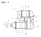
Fig. 1 comprising aparticulate filter 3 for capture of particulates inexhaust gas 1 from an engine and a selective reduction catalyst 4 downstream of theparticulate filter 3 and having a property capable of selectively reacting NOx with ammonia even in the presence of oxygen; theparticulate filter 3 and the selective reduction catalyst 4 are encased bycasings 5 and 6, respectively, and incorporated in parallel with each other in anexhaust pipe 2 through which theexhaust gas 1 from the engine flows; and an exit end of theparticulate filter 3 is connected with an entry end of the selective reduction catalyst 4 through an S-shaped communication passage 7 so that theexhaust gas 1 discharged from the exit end of theparticulate filter 3 is turned back in an opposite direction and is guided to the entry end of the adjacent selective reduction catalyst 4. - The
communication passage 7 is the S-shaped structure comprising agas gathering chamber 7A encompassing the exit end of theparticulate filter 3 to gather theexhaust gas 1 just discharged from the exit end through substantially perpendicular turnabout, amixing pipe 7B for extraction of the gatheredexhaust gas 1 in thechamber 7A in a direction opposite to that of the exhaust gas flow in theparticulate filter 3 and agas dispersing chamber 7C for dispersion of theexhaust gas 1 from themixing pipe 7B through substantially perpendicular turnabout and for encompassing of the entry end of the selective reduction catalyst 4 to guide the dispersedexhaust gas 1 to the entry end of the catalyst. The entry end of themixing pipe 7B is centrally provided with a urea water adding injector 8 (urea water adding means) for addition of the urea water into the mixing pipe 78 and directed to the exit end of themixing pipe 7B. - In the example illustrated, an oxidation catalyst 9 is installed inside the
casing 5 before theparticulate filter 3 to perform an oxidation treatment of unburned fuel in theexhaust gas 1. Anammonia reducing catalyst 10 is installed inside the casing 6 after the selective reduction catalyst 4 to perform an oxidation treatment of surplus ammonia. - With such a configuration employed, the particulates in the
exhaust gas 1 are captured by theparticulate filter 3; and, downstream thereof, the urea water is added in theexhaust gas 1 midway of themixing pipe 7B by the ureawater adding injector 8 and is thermally decomposed into ammonia and carbon dioxide; then, on the selective reduction catalyst 4, NOx in theexhaust gas 1 is well reduced and purified by the ammonia. As a result, the simultaneous reduction of the particulates and NOx in theexhaust gas 1 can be achieved. - In this case, the fact that the
exhaust gas 1 discharged from the exit end of theparticulate filter 3 is turned around in the opposite direction by thecommunication passage 7 and then guided to the entry end of the adjacent selective reduction catalyst 4 ensures a long distance from the added position of the urea water to the selective reduction catalyst 4 and ensures a sufficient reaction time for production of ammonia from the urea water. - Moreover, the fact that the
particulate filter 3 and the selective reduction catalyst 4 are arranged in parallel with each other and thecommunication passage 7 is arranged between and alongside of theparticulate filter 3 and selective reduction catalyst 4 makes an overall configuration compact in size, thereby substantially improving the mountability on the vehicle. - A conventional technology document related to this type of exhaust emission control device with a
particulate filter 3 and a selective reduction catalyst 4 arranged in parallel with each other and interconnected through an S-shaped communication passage 7 is, for example, the followingPatent literature 1. -
- [Patent Literature 1]
JP 2008-215286A - As disclosed in the
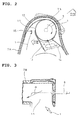
above Patent literature 1, employed at the added position of the urea water by the ureawater adding injector 8 is amixer structure 15 which tangentially guides theexhaust gas 1 from thegas gathering chamber 7A to openingsections 11 at the entry end of thecylindrical mixing pipe 7B shown inFig. 2 byguide fins exhaust gas 1, and the urea water from the ureawater adding injector 8 being added centrally of the swirling flow, thereby enhancing a mixing performance of the urea water with theexhaust gas 1. This brings about a fear that increasing the added amount of the urea water to seek after higher NOx emission control would result in, as shown inFig. 3 , formation of a flow of the urea water ungasified which runs on an inner periphery of themixing pipe 7B along a swirling flow α of theexhaust gas 1 across portions of theopening sections 11 down toward theparticulate filter 3. - Specifically, it is feared that running of part of the urea water from the
opening sections 11 down toward theparticulate filter 3 leads to not all of the urea water added by theinjector 8 being guided as ammonia to the selective reduction catalyst 4, adversely affecting on NOx emission control performance and added amount control of the urea water. - Moreover, structural materials upstream of the added position of the urea water only have a corrosion resistance against exhaust gas components, so that there is a fear that highly corrosive ammonium carbide, which may be produced in the course of a transformation of the urea water having run down toward the
particulate filter 3 into ammonia, induces a rapidly progressive corrosion. - The invention was made in view of the above and has its object to prevent a urea water from running from opening sections at an entry end of a mixing pipe down toward an upstream side.
- The invention is directed to an exhaust emission control device comprising a selective reduction catalyst for reacting NOx in an exhaust gas with ammonia, urea water adding means for adding a urea water into the exhaust gas upstream of said selective reduction catalyst and a cylindrical mixing pipe as a connection between said urea water adding means and said selective reduction catalyst, an entry end of said mixing pipe being formed with circumferential opening sections and provided with guide fins for guiding the exhaust gas to said opening sections tangentially of said entry end to thereby provide a mixer structure, said urea water adding means being arranged centrally on the entry end of said mixing pipe and directed toward an exit end thereof for addition of the urea water into a swirling flow of the exhaust gas caused by said mixer structure, characterized in that said opening sections are formed along said swirling flow.
- Thus, according to the configuration, even if the added amount of the urea water is increased for enhanced NOx emission control to cause a flow of the ungasified urea water running on the inner periphery of the mixing pipe along the swirling flow of the exhaust gas, the opening sections at the entry end of the mixing pipe formed along said swirling flow will cause the flow of the ungasified urea water along the swirling flow to run along the opening sections and not across portions of the opening sections, thereby preventing the urea water from running from the opening sections down toward the upstream side.
- In the invention, it is preferable that a particulate filter is arranged upstream of the added position of the urea water by the urea water adding means and that a positional relationship between an exit end face of said particulate filter and the opening sections at the entry end of the mixing pipe is shifted axially of said mixing pipe such that an angle of inflow of the exhaust gas having passed through said particulate filter to said opening sections is acute relative to an axis of said mixing pipe.
- Such configuration decreases the inflow angle of the exhaust gas having passed through the particulate filter to the opening sections and directs a vector of the flow of the exhaust gas when running to the opening sections toward the exit end of the mixing pipe, which makes it possible to direct vectors of the swirling flow and of the flow of the urea water along the swirling flow more strongly toward the exit end of the mixing pipe, leading to facilitated running of the flow of the urea water over the opening sections and further reliable prevention of the urea water from flowing from the opening sections down toward the upstream side.
- Moreover, the fact that the angle made by an inflow direction of the exhaust gas having passed through the particulate filter to the opening sections and a spraying direction of the urea water adding means becomes shallower lessens an effect of the flow of the exhaust gas on the spraying of the urea water, which prevents the spraying of the urea water adding means from being fanned by the flow of the exhaust gas into direct hit and lingering-around of the urea water on and at stagnant areas off the flow of the exhaust gas and a resultant partial corrosion.
- According to the exhaust emission control device of the invention described above, various excellent effects can be exhibited as described below.
- (I) According to the invention claimed in
claim 1, even if the added amount of the urea water is increased so as to enhance NOx emission control performance and thus the urea water not gasified forms a flow running on the inner periphery of the mixing pipe along the swirling flow of the exhaust gas, the urea water can be prevented from running from the opening sections at the entry end of the mixing pipe down toward the upstream side and therefore, all of the urea water added by the urea water adding means can be guided as ammonia to the selective reduction catalyst to maintain well the NOx emission control performance and the added amount control of the urea water and to prevent occurrence of corrosion attributable to the urea water flowing down toward the upstream side. - (II) According to the invention claimed in
claim 2, the inflow angle of the exhaust gas having passed through the particulate filter to the opening sections is made small so that a vector of the flow of the exhaust gas when running to the opening sections can be directed toward the exit end of the mixing pipe. As a result, vectors of the swirling flow and of the flow of the urea water along the swirling flow can be directed more strongly toward the exit end of the mixing pipe, leading to facilitated running of the flow of the urea water over the opening sections and further reliable prevention of the urea water from flowing from the opening sections down toward the upstream side. - (III) According to the invention claimed in
claim 2, the angle made by the inflow direction of the exhaust gas to the opening sections and the spraying direction of the urea water adding means can be made shallow to lessen the effect of the flow of the exhaust gas on the spraying of the urea water, which can prevent the spray from the urea water adding means from being fanned by the exhaust gas flow into direct hit and lingering-around of the urea water on and at the stagnant areas off the flow of the exhaust gas and a resultant partial corrosion. -
-
Fig. 1 is a plan view of a conventional exhaust emission control device; -
Fig. 2 is a sectional view showing particulars of a substantial part inFig. 1 ; -
Fig. 3 is a sectional view taken along arrowed line III-III inFig. 2 ; -
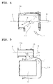
Fig. 4 is a sectional view showing an embodiment of the invention; -
Fig. 5 is a sectional view showing a construction around an entry end of a mixing pipe shown inFig. 4 ; -
Fig. 6 is a sectional view showing a further embodiment of the invention; and -
Fig. 7 is a sectional view of a still further embodiment of the invention. - Embodiments of the invention will be described with reference to the drawings.
-
Figs. 4 and 5 show an embodiment of the invention in which parts similar to those inFigs. 1-3 are represented by same reference numerals. - As shown in
Fig. 4 , the embodiment is characteristic in thatopening sections 11 at an entry end of themixing pipe 7B of the exhaust emission control device configured similarly to that illustrated inFigs. 1-3 are formed along the swirling flow α of theexhaust gas 1 caused by the mixer structure 15 (seeFig. 2 ). - Specifically, unlike existing
opening sections 11 each opened in a substantially simple rectangular shape as shown by a two-dot chain line inFig. 4 , oneside 11a of theopening section 11 is formed along the swirling flow α, inclined at an angle X relative to a direction parallel to an axis of themixing pipe 7B (O inFigs. 4 and 5 represents the axis of themixing pipe 7B) as shown by a solid line inFig. 4 . - Moreover, as shown in
Fig. 5 , this embodiment is configured such that a positional relationship of an exit end face of theparticulate filter 3 and theopening sections 11 at the entry end of themixing pipe 7B is shifted axially of themixing pipe 7B so that an inflow angle θ of theexhaust gas 1 having passed through theparticulate filter 3 to theopening sections 11 is acute relative to the axis of themixing pipe 7B. - While the illustration of the guide fins 12, 13 and 14 (see
Fig. 2 ) is omitted fromFigs. 4 and 5 for the convenience of description, it goes without saying that the guide fins 12, 13 and 14 (seeFig. 2 ) are arranged to tangentially guide theexhaust gas 1 to theopening sections 11 as earlier described inFigs. 1-3 . - Thus, with the exhaust emission control device configured as above, even if the added amount of the urea water is increased for enhancement of the NOx emission control performance and thus the urea water not gasified forms the flow running on the inner periphery of the
mixing pipe 7B along the swirling flow α of theexhaust gas 1, the flow of the urea water along the swirling flow α runs along theopening sections 11 and does not form the flow running across portions of theopening sections 11 at the entry end of themixing pipe 7B since theopening sections 11 are formed along the swirling flow α. As a result, the urea water is prevented from running from theopening sections 11 down toward the particulate filter 3 (toward the upstream side). - In addition, this embodiment is particularly configured such that the inflow angle θ of the
exhaust gas 1 having passed through theparticulate filter 3 to theopening sections 11 is acute relative to the axis of themixing pipe 7B, so that the inflow angle θ of theexhaust gas 1 having passed through theparticulate filter 3 to theopening sections 11 becomes small and a vector of the flow of theexhaust gas 1 when running to theopening sections 11 is directed toward the exit end of themixing pipe 7B (left side inFig. 5 ). - This makes it possible to direct the vectors of the swirling flow α and of the flow of the urea water along the swirling flow α more strongly toward the exit end of the
mixing pipe 7B, which facilitates the running of the flow of the urea water over theopening sections 11, further suppressing flowing-down of the urea water from theopening sections 11 toward theparticulate filter 3. - Moreover, with the angle made by the direction of the inflow of the
exhaust gas 1 having passed through theparticulate filter 3 to theopening sections 11 and the spraying direction of the urea water adding injector 8 (see arrowed dotted line inFig. 5 ) becoming shallow, the effect of the flow of theexhaust gas 1 on the spraying of the urea water is lessened, so that the spray from the ureawater adding injector 8 is prevented from being fanned by the flow of theexhaust gas 1 into direct hit and lingering-around of the urea water on and atstagnant areas 16 off the flow of theexhaust gas 1 and a resultant partial corrosion. - Therefore, according to the above embodiment, even if the added amount of the urea water being increased for enhancement of the NOx emission control performance and the urea water not gasified forms the flow running on the inner periphery of the
mixing pipe 7B along the swirling flow α of theexhaust gas 1, the urea water can be prevented from running from theopening sections 11 at the entry end of themixing pipe 7B down toward theparticulate filter 3, so that all amount of the urea water added by the ureawater adding injector 8 can be guided as ammonia to the selective reduction catalyst, making it possible to maintain well the NOx emission control performance and the added amount control of the urea water and to prevent occurrence of the corrosion attributable to the urea water flowing down toward theparticulate filter 3. - Since the inflow angle θ of the
exhaust gas 1 having passed through theparticulate filter 3 to theopening sections 11 is made small so that a vector of the flow of theexhaust gas 1 when running to theopening sections 11 can be directed toward the exit end of themixing pipe 7B, the vectors of the swirling flow α and the flow of the urea water along the swirling flow α are directed more strongly toward the exit end of themixing pipe 7B, which can facilitate the running of the flow of the urea water over theopening sections 11 and can prevent more reliably the flowing-down of the urea water from theopening sections 11 toward theparticulate filter 3. - Furthermore, since the angle made by the direction of the inflow of the
exhaust gas 1 to theopening sections 11 and the spraying direction of the ureawater adding injector 8 is made shallow so that the effect of the flow of theexhaust gas 1 on the spraying of the urea water can be lessened, which prevents the spraying of the ureawater adding injector 8 from being fanned by the flow of theexhaust gas 1 into directly hit and lingering-around of the urea water on and at thestagnant areas 16 off the flow of theexhaust gas 1 and a resultant partial corrosion. -
Fig. 6 shows a further embodiment of the invention. The oneside 11a of theopening section 11 described in the embodiment inFig. 4 , at its terminating portion toward an exit side of themixing pipe 7B, is inclined at angle Y (angle relative to the direction parallel to the axis of themixing pipe 7B) which is deeper than the angle X. Since this makes it possible to guide the flow of the urea water along the oneside 11a of theopening section 11 smoothly and continuously toward the downstream side by the further angle Y, the flowing down of the urea water from theopening sections 11 can be prevented with further reliability. - As is shown in a still further embodiment of the invention in
Fig. 7 , the oneside 11a of theopening section 11, at its terminating portion toward the exit side of themixing pipe 7B, may be inclined by two steps of angles Y and Z (X < Y < Z). Furthermore, the oneside 11a may be alternatively inclined step by step by combining three or more steps of angles or may be inclined by joining curves continuously. - It is to be understood that an exhaust emission control device according to the invention is not limited to the above embodiments and that various changes and modifications may be made without departing from the scope of the invention.
-
- 1
- exhaust gas
- 3
- particulate filter
- 4
- selective reduction catalyst
- 7B
- mixing pipe
- 8
- urea water adding injector (urea water adding means)
- 11
- opening
- 12
- guide fin
- 13
- guide fin
- 14
- guide fin
- 15
- mixer structure
- α
- swirling flow
- θ
- inflow angle
Claims (2)
- An exhaust emission control device comprising a selective reduction catalyst for reacting NOx in an exhaust gas with ammonia, urea water adding means for adding a urea water into the exhaust gas upstream of said selective reduction catalyst and a cylindrical mixing pipe as a connection between said urea water adding means and said selective reduction catalyst, an entry end of said mixing pipe being formed with circumferential opening sections and provided with guide fins for guiding the exhaust gas to said opening sections tangentially of said entry end to thereby provide a mixer structure, said urea water adding means being arranged centrally on the entry end of said mixing pipe and directed toward an exit end thereof for addition of the urea water into a swirling flow of the exhaust gas caused by said mixer structure, wherein said opening sections are formed along said swirling flow.
- The exhaust emission control device as claimed in claim 1, wherein a particulate filter is arranged upstream of the added position of the urea water by the urea water adding means and wherein a positional relationship between an exit end face of said particulate filter and the opening sections at the entry end of the mixing pipe is shifted axially of said mixing pipe such that an angle of inflow of the exhaust gas having passed through said particulate filter to said opening sections is acute relative to an axis of said mixing pipe.
Applications Claiming Priority (2)
| Application Number | Priority Date | Filing Date | Title |
|---|---|---|---|
| JP2009291798A JP5329383B2 (en) | 2009-12-24 | 2009-12-24 | Exhaust purification device |
| PCT/JP2010/007399 WO2011077703A1 (en) | 2009-12-24 | 2010-12-21 | Exhaust purification device |
Publications (3)
| Publication Number | Publication Date |
|---|---|
| EP2518287A1 true EP2518287A1 (en) | 2012-10-31 |
| EP2518287A4 EP2518287A4 (en) | 2014-12-10 |
| EP2518287B1 EP2518287B1 (en) | 2016-11-09 |
Family
ID=44195257
Family Applications (1)
| Application Number | Title | Priority Date | Filing Date |
|---|---|---|---|
| EP10838942.0A Not-in-force EP2518287B1 (en) | 2009-12-24 | 2010-12-21 | Exhaust purification device |
Country Status (6)
| Country | Link |
|---|---|
| US (1) | US8813481B2 (en) |
| EP (1) | EP2518287B1 (en) |
| JP (1) | JP5329383B2 (en) |
| CN (1) | CN102762828B (en) |
| AU (1) | AU2010334192B2 (en) |
| WO (1) | WO2011077703A1 (en) |
Cited By (4)
| Publication number | Priority date | Publication date | Assignee | Title |
|---|---|---|---|---|
| GB2515450A (en) * | 2013-03-18 | 2014-12-31 | Alexander Dennis Ltd | Passenger service vehicle |
| EP2823880A1 (en) * | 2013-07-08 | 2015-01-14 | Toyota Jidosha Kabushiki Kaisha | Exhaust gas purification appratus for an internal combustion engine |
| CN110410185A (en) * | 2019-07-03 | 2019-11-05 | 东风商用车有限公司 | A kind of crystallization-preventive close-coupled urea mixing device |
| EP3536393A3 (en) * | 2018-02-15 | 2020-01-01 | MAN Truck & Bus SE | Device for mixing exhaust gas and an additive |
Families Citing this family (14)
| Publication number | Priority date | Publication date | Assignee | Title |
|---|---|---|---|---|
| JP6053096B2 (en) * | 2012-01-12 | 2016-12-27 | 日野自動車株式会社 | Exhaust purification device |
| GB201207201D0 (en) * | 2012-04-24 | 2012-06-06 | Perkins Engines Co Ltd | Emissions cleaning module for a diesel engine |
| US9133601B2 (en) * | 2012-10-16 | 2015-09-15 | Komatsu Ltd. | Hydraulic excavator |
| WO2014155507A1 (en) * | 2013-03-26 | 2014-10-02 | 株式会社小松製作所 | Work vehicle and wheel loader |
| JP6185366B2 (en) * | 2013-10-31 | 2017-08-23 | 日野自動車株式会社 | Exhaust purification device |
| US9534525B2 (en) | 2015-05-27 | 2017-01-03 | Tenneco Automotive Operating Company Inc. | Mixer assembly for exhaust aftertreatment system |
| US10174658B2 (en) * | 2016-07-20 | 2019-01-08 | Faurecia Emissions Control Technologies, Usa, Llc | Flow diverter to mitigate deposits in a doser cone |
| JP6756644B2 (en) * | 2017-03-09 | 2020-09-16 | 日野自動車株式会社 | Exhaust purification device |
| CN107120162B (en) * | 2017-06-29 | 2023-01-20 | 杭州银轮科技有限公司 | Mixing device for engine tail gas aftertreatment system |
| US10605143B2 (en) * | 2017-07-14 | 2020-03-31 | Ford Global Technologies, Llc | Exhaust gas mixer |
| DE102018124025A1 (en) * | 2018-09-28 | 2020-04-02 | Man Truck & Bus Se | Device for admixing a liquid reducing agent for the exhaust gas of an internal combustion engine and motor vehicle |
| JP7443822B2 (en) * | 2020-02-28 | 2024-03-06 | 三菱ふそうトラック・バス株式会社 | Exhaust purification device |
| CN113775395B (en) * | 2021-10-18 | 2022-07-15 | 无锡威孚力达催化净化器有限责任公司 | Font mixing arrangement and aftertreatment system return |
| CN114263518B (en) * | 2022-01-28 | 2023-03-21 | 无锡威孚力达催化净化器有限责任公司 | Dispersion crushing and arc plate diversion type urea mixer |
Family Cites Families (9)
| Publication number | Priority date | Publication date | Assignee | Title |
|---|---|---|---|---|
| JP2005127271A (en) * | 2003-10-27 | 2005-05-19 | Babcock Hitachi Kk | Urea water vaporizer |
| GB2416718A (en) * | 2004-07-29 | 2006-02-08 | Eminox Ltd | Gas treatment apparatus |
| CN1923344B (en) * | 2004-12-07 | 2010-06-16 | 陈妙生 | Waste gas purifier |
| JP2008051011A (en) * | 2006-08-24 | 2008-03-06 | Toyota Motor Corp | Exhaust gas purification system for internal combustion engine |
| JP4928304B2 (en) * | 2007-02-23 | 2012-05-09 | 日野自動車株式会社 | Exhaust purification device |
| JP4823944B2 (en) * | 2007-03-07 | 2011-11-24 | 日野自動車株式会社 | Exhaust purification device |
| JP2009091984A (en) * | 2007-10-09 | 2009-04-30 | Mitsubishi Fuso Truck & Bus Corp | Exhaust emission control device |
| JP5017065B2 (en) * | 2007-11-21 | 2012-09-05 | 日野自動車株式会社 | Exhaust purification device |
| US20100186381A1 (en) * | 2009-01-26 | 2010-07-29 | Caterpillar Inc | Exhaust system thermal enclosure |
-
2009
- 2009-12-24 JP JP2009291798A patent/JP5329383B2/en not_active Expired - Fee Related
-
2010
- 2010-12-21 WO PCT/JP2010/007399 patent/WO2011077703A1/en not_active Ceased
- 2010-12-21 AU AU2010334192A patent/AU2010334192B2/en not_active Ceased
- 2010-12-21 EP EP10838942.0A patent/EP2518287B1/en not_active Not-in-force
- 2010-12-21 CN CN201080059096.9A patent/CN102762828B/en not_active Expired - Fee Related
- 2010-12-21 US US13/515,379 patent/US8813481B2/en active Active
Cited By (7)
| Publication number | Priority date | Publication date | Assignee | Title |
|---|---|---|---|---|
| GB2515450A (en) * | 2013-03-18 | 2014-12-31 | Alexander Dennis Ltd | Passenger service vehicle |
| GB2515450B (en) * | 2013-03-18 | 2017-03-22 | Alexander Dennis Ltd | Passenger service vehicle |
| US9732647B2 (en) | 2013-03-18 | 2017-08-15 | Alexander Dennis Limited | Passenger service vehicle |
| EP2823880A1 (en) * | 2013-07-08 | 2015-01-14 | Toyota Jidosha Kabushiki Kaisha | Exhaust gas purification appratus for an internal combustion engine |
| EP3536393A3 (en) * | 2018-02-15 | 2020-01-01 | MAN Truck & Bus SE | Device for mixing exhaust gas and an additive |
| US10851697B2 (en) | 2018-02-15 | 2020-12-01 | Man Truck & Bus Ag | Apparatus for mixing exhaust gas and an additive |
| CN110410185A (en) * | 2019-07-03 | 2019-11-05 | 东风商用车有限公司 | A kind of crystallization-preventive close-coupled urea mixing device |
Also Published As
| Publication number | Publication date |
|---|---|
| AU2010334192B2 (en) | 2014-06-12 |
| JP5329383B2 (en) | 2013-10-30 |
| AU2010334192A1 (en) | 2012-07-12 |
| US20120255287A1 (en) | 2012-10-11 |
| EP2518287A4 (en) | 2014-12-10 |
| JP2011132855A (en) | 2011-07-07 |
| US8813481B2 (en) | 2014-08-26 |
| EP2518287B1 (en) | 2016-11-09 |
| CN102762828A (en) | 2012-10-31 |
| CN102762828B (en) | 2015-04-29 |
| WO2011077703A1 (en) | 2011-06-30 |
| WO2011077703A9 (en) | 2012-06-28 |
Similar Documents
| Publication | Publication Date | Title |
|---|---|---|
| EP2518287B1 (en) | Exhaust purification device | |
| US8245504B2 (en) | Exhaust emission control device | |
| US8397492B2 (en) | Exhaust emission control device | |
| US8347610B2 (en) | Exhaust emission control device | |
| EP2184455B1 (en) | Injector mounting structure | |
| EP2224108B1 (en) | Exhaust emission control device | |
| US8327630B2 (en) | Exhaust emission control device | |
| JP4823944B2 (en) | Exhaust purification device | |
| EP2282028A1 (en) | Exhaust gas purification apparatus | |
| EP3168440A1 (en) | Mixing structure | |
| US10626767B2 (en) | Exhaust purification apparatus | |
| AU2011228545B2 (en) | Exhaust emission control device | |
| EP3604754A1 (en) | Reactor | |
| EP3489480A1 (en) | Scr mixer and scr device comprising same | |
| US10626771B2 (en) | Mixing structure | |
| EP3604755A1 (en) | Reactor | |
| US20200040791A1 (en) | Exhaust gas purification apparatus |
Legal Events
| Date | Code | Title | Description |
|---|---|---|---|
| PUAI | Public reference made under article 153(3) epc to a published international application that has entered the european phase |
Free format text: ORIGINAL CODE: 0009012 |
|
| 17P | Request for examination filed |
Effective date: 20120719 |
|
| AK | Designated contracting states |
Kind code of ref document: A1 Designated state(s): AL AT BE BG CH CY CZ DE DK EE ES FI FR GB GR HR HU IE IS IT LI LT LU LV MC MK MT NL NO PL PT RO RS SE SI SK SM TR |
|
| DAX | Request for extension of the european patent (deleted) | ||
| A4 | Supplementary search report drawn up and despatched |
Effective date: 20141110 |
|
| RIC1 | Information provided on ipc code assigned before grant |
Ipc: F01N 3/24 20060101ALI20141104BHEP Ipc: F01N 3/20 20060101ALI20141104BHEP Ipc: B01D 53/94 20060101ALI20141104BHEP Ipc: F01N 13/14 20100101ALI20141104BHEP Ipc: F01N 3/08 20060101AFI20141104BHEP Ipc: F01N 13/02 20100101ALI20141104BHEP Ipc: F01N 3/28 20060101ALI20141104BHEP |
|
| GRAP | Despatch of communication of intention to grant a patent |
Free format text: ORIGINAL CODE: EPIDOSNIGR1 |
|
| INTG | Intention to grant announced |
Effective date: 20160622 |
|
| GRAS | Grant fee paid |
Free format text: ORIGINAL CODE: EPIDOSNIGR3 |
|
| GRAA | (expected) grant |
Free format text: ORIGINAL CODE: 0009210 |
|
| AK | Designated contracting states |
Kind code of ref document: B1 Designated state(s): AL AT BE BG CH CY CZ DE DK EE ES FI FR GB GR HR HU IE IS IT LI LT LU LV MC MK MT NL NO PL PT RO RS SE SI SK SM TR |
|
| REG | Reference to a national code |
Ref country code: GB Ref legal event code: FG4D |
|
| REG | Reference to a national code |
Ref country code: AT Ref legal event code: REF Ref document number: 844134 Country of ref document: AT Kind code of ref document: T Effective date: 20161115 Ref country code: CH Ref legal event code: EP |
|
| REG | Reference to a national code |
Ref country code: IE Ref legal event code: FG4D |
|
| REG | Reference to a national code |
Ref country code: FR Ref legal event code: PLFP Year of fee payment: 7 |
|
| REG | Reference to a national code |
Ref country code: DE Ref legal event code: R096 Ref document number: 602010037924 Country of ref document: DE |
|
| PG25 | Lapsed in a contracting state [announced via postgrant information from national office to epo] |
Ref country code: LV Free format text: LAPSE BECAUSE OF FAILURE TO SUBMIT A TRANSLATION OF THE DESCRIPTION OR TO PAY THE FEE WITHIN THE PRESCRIBED TIME-LIMIT Effective date: 20161109 |
|
| REG | Reference to a national code |
Ref country code: LT Ref legal event code: MG4D |
|
| REG | Reference to a national code |
Ref country code: NL Ref legal event code: MP Effective date: 20161109 |
|
| REG | Reference to a national code |
Ref country code: AT Ref legal event code: MK05 Ref document number: 844134 Country of ref document: AT Kind code of ref document: T Effective date: 20161109 |
|
| PG25 | Lapsed in a contracting state [announced via postgrant information from national office to epo] |
Ref country code: NO Free format text: LAPSE BECAUSE OF FAILURE TO SUBMIT A TRANSLATION OF THE DESCRIPTION OR TO PAY THE FEE WITHIN THE PRESCRIBED TIME-LIMIT Effective date: 20170209 Ref country code: SE Free format text: LAPSE BECAUSE OF FAILURE TO SUBMIT A TRANSLATION OF THE DESCRIPTION OR TO PAY THE FEE WITHIN THE PRESCRIBED TIME-LIMIT Effective date: 20161109 Ref country code: NL Free format text: LAPSE BECAUSE OF FAILURE TO SUBMIT A TRANSLATION OF THE DESCRIPTION OR TO PAY THE FEE WITHIN THE PRESCRIBED TIME-LIMIT Effective date: 20161109 Ref country code: LT Free format text: LAPSE BECAUSE OF FAILURE TO SUBMIT A TRANSLATION OF THE DESCRIPTION OR TO PAY THE FEE WITHIN THE PRESCRIBED TIME-LIMIT Effective date: 20161109 Ref country code: GR Free format text: LAPSE BECAUSE OF FAILURE TO SUBMIT A TRANSLATION OF THE DESCRIPTION OR TO PAY THE FEE WITHIN THE PRESCRIBED TIME-LIMIT Effective date: 20170210 |
|
| PG25 | Lapsed in a contracting state [announced via postgrant information from national office to epo] |
Ref country code: PT Free format text: LAPSE BECAUSE OF FAILURE TO SUBMIT A TRANSLATION OF THE DESCRIPTION OR TO PAY THE FEE WITHIN THE PRESCRIBED TIME-LIMIT Effective date: 20170309 Ref country code: HR Free format text: LAPSE BECAUSE OF FAILURE TO SUBMIT A TRANSLATION OF THE DESCRIPTION OR TO PAY THE FEE WITHIN THE PRESCRIBED TIME-LIMIT Effective date: 20161109 Ref country code: PL Free format text: LAPSE BECAUSE OF FAILURE TO SUBMIT A TRANSLATION OF THE DESCRIPTION OR TO PAY THE FEE WITHIN THE PRESCRIBED TIME-LIMIT Effective date: 20161109 Ref country code: BE Free format text: LAPSE BECAUSE OF NON-PAYMENT OF DUE FEES Effective date: 20161231 Ref country code: FI Free format text: LAPSE BECAUSE OF FAILURE TO SUBMIT A TRANSLATION OF THE DESCRIPTION OR TO PAY THE FEE WITHIN THE PRESCRIBED TIME-LIMIT Effective date: 20161109 Ref country code: RS Free format text: LAPSE BECAUSE OF FAILURE TO SUBMIT A TRANSLATION OF THE DESCRIPTION OR TO PAY THE FEE WITHIN THE PRESCRIBED TIME-LIMIT Effective date: 20161109 Ref country code: ES Free format text: LAPSE BECAUSE OF FAILURE TO SUBMIT A TRANSLATION OF THE DESCRIPTION OR TO PAY THE FEE WITHIN THE PRESCRIBED TIME-LIMIT Effective date: 20161109 Ref country code: AT Free format text: LAPSE BECAUSE OF FAILURE TO SUBMIT A TRANSLATION OF THE DESCRIPTION OR TO PAY THE FEE WITHIN THE PRESCRIBED TIME-LIMIT Effective date: 20161109 Ref country code: IS Free format text: LAPSE BECAUSE OF FAILURE TO SUBMIT A TRANSLATION OF THE DESCRIPTION OR TO PAY THE FEE WITHIN THE PRESCRIBED TIME-LIMIT Effective date: 20170309 |
|
| PG25 | Lapsed in a contracting state [announced via postgrant information from national office to epo] |
Ref country code: CZ Free format text: LAPSE BECAUSE OF FAILURE TO SUBMIT A TRANSLATION OF THE DESCRIPTION OR TO PAY THE FEE WITHIN THE PRESCRIBED TIME-LIMIT Effective date: 20161109 Ref country code: EE Free format text: LAPSE BECAUSE OF FAILURE TO SUBMIT A TRANSLATION OF THE DESCRIPTION OR TO PAY THE FEE WITHIN THE PRESCRIBED TIME-LIMIT Effective date: 20161109 Ref country code: RO Free format text: LAPSE BECAUSE OF FAILURE TO SUBMIT A TRANSLATION OF THE DESCRIPTION OR TO PAY THE FEE WITHIN THE PRESCRIBED TIME-LIMIT Effective date: 20161109 Ref country code: DK Free format text: LAPSE BECAUSE OF FAILURE TO SUBMIT A TRANSLATION OF THE DESCRIPTION OR TO PAY THE FEE WITHIN THE PRESCRIBED TIME-LIMIT Effective date: 20161109 Ref country code: SK Free format text: LAPSE BECAUSE OF FAILURE TO SUBMIT A TRANSLATION OF THE DESCRIPTION OR TO PAY THE FEE WITHIN THE PRESCRIBED TIME-LIMIT Effective date: 20161109 |
|
| REG | Reference to a national code |
Ref country code: CH Ref legal event code: PL |
|
| REG | Reference to a national code |
Ref country code: DE Ref legal event code: R097 Ref document number: 602010037924 Country of ref document: DE |
|
| PG25 | Lapsed in a contracting state [announced via postgrant information from national office to epo] |
Ref country code: IT Free format text: LAPSE BECAUSE OF FAILURE TO SUBMIT A TRANSLATION OF THE DESCRIPTION OR TO PAY THE FEE WITHIN THE PRESCRIBED TIME-LIMIT Effective date: 20161109 Ref country code: SM Free format text: LAPSE BECAUSE OF FAILURE TO SUBMIT A TRANSLATION OF THE DESCRIPTION OR TO PAY THE FEE WITHIN THE PRESCRIBED TIME-LIMIT Effective date: 20161109 Ref country code: BG Free format text: LAPSE BECAUSE OF FAILURE TO SUBMIT A TRANSLATION OF THE DESCRIPTION OR TO PAY THE FEE WITHIN THE PRESCRIBED TIME-LIMIT Effective date: 20170209 Ref country code: BE Free format text: LAPSE BECAUSE OF FAILURE TO SUBMIT A TRANSLATION OF THE DESCRIPTION OR TO PAY THE FEE WITHIN THE PRESCRIBED TIME-LIMIT Effective date: 20161109 |
|
| PLBE | No opposition filed within time limit |
Free format text: ORIGINAL CODE: 0009261 |
|
| STAA | Information on the status of an ep patent application or granted ep patent |
Free format text: STATUS: NO OPPOSITION FILED WITHIN TIME LIMIT |
|
| PG25 | Lapsed in a contracting state [announced via postgrant information from national office to epo] |
Ref country code: MC Free format text: LAPSE BECAUSE OF FAILURE TO SUBMIT A TRANSLATION OF THE DESCRIPTION OR TO PAY THE FEE WITHIN THE PRESCRIBED TIME-LIMIT Effective date: 20161109 |
|
| REG | Reference to a national code |
Ref country code: IE Ref legal event code: MM4A |
|
| 26N | No opposition filed |
Effective date: 20170810 |
|
| PG25 | Lapsed in a contracting state [announced via postgrant information from national office to epo] |
Ref country code: LU Free format text: LAPSE BECAUSE OF NON-PAYMENT OF DUE FEES Effective date: 20161221 Ref country code: LI Free format text: LAPSE BECAUSE OF NON-PAYMENT OF DUE FEES Effective date: 20161231 Ref country code: CH Free format text: LAPSE BECAUSE OF NON-PAYMENT OF DUE FEES Effective date: 20161231 |
|
| REG | Reference to a national code |
Ref country code: FR Ref legal event code: PLFP Year of fee payment: 8 |
|
| PG25 | Lapsed in a contracting state [announced via postgrant information from national office to epo] |
Ref country code: IE Free format text: LAPSE BECAUSE OF NON-PAYMENT OF DUE FEES Effective date: 20161221 Ref country code: SI Free format text: LAPSE BECAUSE OF FAILURE TO SUBMIT A TRANSLATION OF THE DESCRIPTION OR TO PAY THE FEE WITHIN THE PRESCRIBED TIME-LIMIT Effective date: 20161109 |
|
| PG25 | Lapsed in a contracting state [announced via postgrant information from national office to epo] |
Ref country code: HU Free format text: LAPSE BECAUSE OF FAILURE TO SUBMIT A TRANSLATION OF THE DESCRIPTION OR TO PAY THE FEE WITHIN THE PRESCRIBED TIME-LIMIT; INVALID AB INITIO Effective date: 20101221 Ref country code: CY Free format text: LAPSE BECAUSE OF FAILURE TO SUBMIT A TRANSLATION OF THE DESCRIPTION OR TO PAY THE FEE WITHIN THE PRESCRIBED TIME-LIMIT Effective date: 20161109 |
|
| PG25 | Lapsed in a contracting state [announced via postgrant information from national office to epo] |
Ref country code: TR Free format text: LAPSE BECAUSE OF FAILURE TO SUBMIT A TRANSLATION OF THE DESCRIPTION OR TO PAY THE FEE WITHIN THE PRESCRIBED TIME-LIMIT Effective date: 20161109 Ref country code: MK Free format text: LAPSE BECAUSE OF FAILURE TO SUBMIT A TRANSLATION OF THE DESCRIPTION OR TO PAY THE FEE WITHIN THE PRESCRIBED TIME-LIMIT Effective date: 20161109 |
|
| PG25 | Lapsed in a contracting state [announced via postgrant information from national office to epo] |
Ref country code: MT Free format text: LAPSE BECAUSE OF NON-PAYMENT OF DUE FEES Effective date: 20161221 |
|
| PGFP | Annual fee paid to national office [announced via postgrant information from national office to epo] |
Ref country code: FR Payment date: 20191213 Year of fee payment: 10 |
|
| PGFP | Annual fee paid to national office [announced via postgrant information from national office to epo] |
Ref country code: DE Payment date: 20191219 Year of fee payment: 10 Ref country code: GB Payment date: 20191211 Year of fee payment: 10 |
|
| PG25 | Lapsed in a contracting state [announced via postgrant information from national office to epo] |
Ref country code: AL Free format text: LAPSE BECAUSE OF FAILURE TO SUBMIT A TRANSLATION OF THE DESCRIPTION OR TO PAY THE FEE WITHIN THE PRESCRIBED TIME-LIMIT Effective date: 20161109 |
|
| REG | Reference to a national code |
Ref country code: DE Ref legal event code: R119 Ref document number: 602010037924 Country of ref document: DE |
|
| GBPC | Gb: european patent ceased through non-payment of renewal fee |
Effective date: 20201221 |
|
| PG25 | Lapsed in a contracting state [announced via postgrant information from national office to epo] |
Ref country code: FR Free format text: LAPSE BECAUSE OF NON-PAYMENT OF DUE FEES Effective date: 20201231 |
|
| PG25 | Lapsed in a contracting state [announced via postgrant information from national office to epo] |
Ref country code: GB Free format text: LAPSE BECAUSE OF NON-PAYMENT OF DUE FEES Effective date: 20201221 Ref country code: DE Free format text: LAPSE BECAUSE OF NON-PAYMENT OF DUE FEES Effective date: 20210701 |