EP2518279A2 - Fan drive planetary gear system integrated carrier and torque frame - Google Patents
Fan drive planetary gear system integrated carrier and torque frame Download PDFInfo
- Publication number
- EP2518279A2 EP2518279A2 EP12166086A EP12166086A EP2518279A2 EP 2518279 A2 EP2518279 A2 EP 2518279A2 EP 12166086 A EP12166086 A EP 12166086A EP 12166086 A EP12166086 A EP 12166086A EP 2518279 A2 EP2518279 A2 EP 2518279A2
- Authority
- EP
- European Patent Office
- Prior art keywords
- gear
- torque frame
- bearing
- shaft
- race
- Prior art date
- Legal status (The legal status is an assumption and is not a legal conclusion. Google has not performed a legal analysis and makes no representation as to the accuracy of the status listed.)
- Granted
Links
Images

Classifications
-
- F—MECHANICAL ENGINEERING; LIGHTING; HEATING; WEAPONS; BLASTING
- F01—MACHINES OR ENGINES IN GENERAL; ENGINE PLANTS IN GENERAL; STEAM ENGINES
- F01D—NON-POSITIVE DISPLACEMENT MACHINES OR ENGINES, e.g. STEAM TURBINES
- F01D25/00—Component parts, details, or accessories, not provided for in, or of interest apart from, other groups
- F01D25/18—Lubricating arrangements
-
- F—MECHANICAL ENGINEERING; LIGHTING; HEATING; WEAPONS; BLASTING
- F16—ENGINEERING ELEMENTS AND UNITS; GENERAL MEASURES FOR PRODUCING AND MAINTAINING EFFECTIVE FUNCTIONING OF MACHINES OR INSTALLATIONS; THERMAL INSULATION IN GENERAL
- F16H—GEARING
- F16H1/00—Toothed gearings for conveying rotary motion
- F16H1/28—Toothed gearings for conveying rotary motion with gears having orbital motion
-
- F—MECHANICAL ENGINEERING; LIGHTING; HEATING; WEAPONS; BLASTING
- F01—MACHINES OR ENGINES IN GENERAL; ENGINE PLANTS IN GENERAL; STEAM ENGINES
- F01D—NON-POSITIVE DISPLACEMENT MACHINES OR ENGINES, e.g. STEAM TURBINES
- F01D25/00—Component parts, details, or accessories, not provided for in, or of interest apart from, other groups
- F01D25/16—Arrangement of bearings; Supporting or mounting bearings in casings
-
- F—MECHANICAL ENGINEERING; LIGHTING; HEATING; WEAPONS; BLASTING
- F02—COMBUSTION ENGINES; HOT-GAS OR COMBUSTION-PRODUCT ENGINE PLANTS
- F02C—GAS-TURBINE PLANTS; AIR INTAKES FOR JET-PROPULSION PLANTS; CONTROLLING FUEL SUPPLY IN AIR-BREATHING JET-PROPULSION PLANTS
- F02C7/00—Features, components parts, details or accessories, not provided for in, or of interest apart form groups F02C1/00 - F02C6/00; Air intakes for jet-propulsion plants
- F02C7/36—Power transmission arrangements between the different shafts of the gas turbine plant, or between the gas-turbine plant and the power user
-
- F—MECHANICAL ENGINEERING; LIGHTING; HEATING; WEAPONS; BLASTING
- F16—ENGINEERING ELEMENTS AND UNITS; GENERAL MEASURES FOR PRODUCING AND MAINTAINING EFFECTIVE FUNCTIONING OF MACHINES OR INSTALLATIONS; THERMAL INSULATION IN GENERAL
- F16C—SHAFTS; FLEXIBLE SHAFTS; ELEMENTS OR CRANKSHAFT MECHANISMS; ROTARY BODIES OTHER THAN GEARING ELEMENTS; BEARINGS
- F16C23/00—Bearings for exclusively rotary movement adjustable for aligning or positioning
- F16C23/02—Sliding-contact bearings
- F16C23/04—Sliding-contact bearings self-adjusting
- F16C23/043—Sliding-contact bearings self-adjusting with spherical surfaces, e.g. spherical plain bearings
- F16C23/045—Sliding-contact bearings self-adjusting with spherical surfaces, e.g. spherical plain bearings for radial load mainly, e.g. radial spherical plain bearings
-
- F—MECHANICAL ENGINEERING; LIGHTING; HEATING; WEAPONS; BLASTING
- F16—ENGINEERING ELEMENTS AND UNITS; GENERAL MEASURES FOR PRODUCING AND MAINTAINING EFFECTIVE FUNCTIONING OF MACHINES OR INSTALLATIONS; THERMAL INSULATION IN GENERAL
- F16H—GEARING
- F16H57/00—General details of gearing
- F16H57/08—General details of gearing of gearings with members having orbital motion
- F16H57/082—Planet carriers
-
- F—MECHANICAL ENGINEERING; LIGHTING; HEATING; WEAPONS; BLASTING
- F16—ENGINEERING ELEMENTS AND UNITS; GENERAL MEASURES FOR PRODUCING AND MAINTAINING EFFECTIVE FUNCTIONING OF MACHINES OR INSTALLATIONS; THERMAL INSULATION IN GENERAL
- F16C—SHAFTS; FLEXIBLE SHAFTS; ELEMENTS OR CRANKSHAFT MECHANISMS; ROTARY BODIES OTHER THAN GEARING ELEMENTS; BEARINGS
- F16C2360/00—Engines or pumps
- F16C2360/23—Gas turbine engines
-
- F—MECHANICAL ENGINEERING; LIGHTING; HEATING; WEAPONS; BLASTING
- F16—ENGINEERING ELEMENTS AND UNITS; GENERAL MEASURES FOR PRODUCING AND MAINTAINING EFFECTIVE FUNCTIONING OF MACHINES OR INSTALLATIONS; THERMAL INSULATION IN GENERAL
- F16H—GEARING
- F16H57/00—General details of gearing
- F16H57/04—Features relating to lubrication or cooling or heating
- F16H57/042—Guidance of lubricant
- F16H57/0427—Guidance of lubricant on rotary parts, e.g. using baffles for collecting lubricant by centrifugal force
-
- Y—GENERAL TAGGING OF NEW TECHNOLOGICAL DEVELOPMENTS; GENERAL TAGGING OF CROSS-SECTIONAL TECHNOLOGIES SPANNING OVER SEVERAL SECTIONS OF THE IPC; TECHNICAL SUBJECTS COVERED BY FORMER USPC CROSS-REFERENCE ART COLLECTIONS [XRACs] AND DIGESTS
- Y02—TECHNOLOGIES OR APPLICATIONS FOR MITIGATION OR ADAPTATION AGAINST CLIMATE CHANGE
- Y02T—CLIMATE CHANGE MITIGATION TECHNOLOGIES RELATED TO TRANSPORTATION
- Y02T50/00—Aeronautics or air transport
- Y02T50/60—Efficient propulsion technologies, e.g. for aircraft
-
- Y—GENERAL TAGGING OF NEW TECHNOLOGICAL DEVELOPMENTS; GENERAL TAGGING OF CROSS-SECTIONAL TECHNOLOGIES SPANNING OVER SEVERAL SECTIONS OF THE IPC; TECHNICAL SUBJECTS COVERED BY FORMER USPC CROSS-REFERENCE ART COLLECTIONS [XRACs] AND DIGESTS
- Y10—TECHNICAL SUBJECTS COVERED BY FORMER USPC
- Y10T—TECHNICAL SUBJECTS COVERED BY FORMER US CLASSIFICATION
- Y10T29/00—Metal working
- Y10T29/49—Method of mechanical manufacture
- Y10T29/49229—Prime mover or fluid pump making
- Y10T29/49236—Fluid pump or compressor making
- Y10T29/49245—Vane type or other rotary, e.g., fan
Definitions
- This disclosure relates to a fan drive gear system integrated carrier and torque frame.
- One type of gas turbine engine includes a fan drive gear system that is mechanically arranged between the turbo-machinery of the engine and a fan.
- the turbo-machinery is composed of two concentric shafts rotating at different speeds containing independent compressors and turbines.
- the turbo-machinery rotationally drives the fan, via the gear system, to move fluid through a nacelle, which divides the fluid flow into two streams.
- An inner stream supplies the turbo-machinery and the outer stream consists of fluid which bypasses the inner stream and is solely compressed and moved by the fan.
- the fan drive gear system is provided by an epicyclic gear train and includes a centrally located input gear driven by the turbo-machinery, intermediate gears circumferentially arranged about and intermeshing with the input gear and a ring gear provided about and intermeshing the intermediate gears.
- the intermediate gears or the ring gear rotationally drives the fan in response to rotation of the input gear.
- the intermediate gears are typically supported in a carrier by a journal extending between spaced apart walls of the carrier.
- the carrier is typically constructed from a high strength metallic alloy such as steel, titanium or nickel.
- the carrier is bolted to a torque frame, which is secured to fixed structure or rotating structure depending upon the particular type of gear system.
- This integrated torque frame includes shafts that directly support the intermediate gears in a cantilevered fashion by conventional rolling element bearings. This arrangement is subjected to vibrational stresses that may cause the integrated torque frame to fail.
- a fan gear drive system includes a torque frame having a base with integrated gear shafts circumferentially spaced relative to one another.
- a fan shaft is integrated with the base, and each shaft provides a shaft axis.
- a bearing assembly is mounted on each of the gear shafts and provides a bearing axis.
- the bearing assembly includes a spherical bearing configured to permit angular movement of the bearing axis relative to the shaft axis.
- a fan drive gear drive lubrication system includes a torque frame supporting multiple gears and has at least one lubrication passage.
- An oil baffle is secured to the torque frame and includes a central opening and multiple circumferentially spaced gear pockets arranged about the central opening to receive the multiple gears.
- the oil baffle includes at least one lubrication passageway in fluid communication with the lubrication passage. At least one tube extends between and fluidly interconnects the lubrication passage and passageway.
- a method of assembling a fan drive gear system includes the step of installing a spherical bearing into a race to provide a bearing assembly.
- the bearing assembly is mounted onto a shaft of a torque frame.
- the torque frame is supported in a front bearing housing by bearings.
- An intermediate gear is installed onto the bearing assembly.
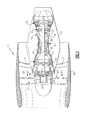
- FIG. 1 An example gas turbine engine 10 is schematically illustrated in Figure 1 .
- the engine 10 includes turbo-machinery 30 having a compressor section 12 and a turbine section 14.
- the turbo-machinery 30 rotationally drives a fan 32, which is arranged in a bypass flow path 33, through an epicyclic gear train 16.
- the turbo-machinery 30 is housed within an inner nacelle 42.
- Flow exit guide vanes 31 arranged within the bypass flow path support the turbo-machinery 30 relative to a fan case, which is housed in a fan nacelle 44.
- a low pressure compressor 18 and a low pressure turbine 20 are mounted on a low pressure spool 22.
- a high pressure compressor 24 and a high pressure turbine 26 are mounted on a high pressure spool 28.
- a combustor section 48 is arranged between the high pressure compressor 24 and the high pressure turbine 26.
- the low pressure spool 22 rotationally drives a flex shaft 46 to which an input gear 36 (sun gear) is mounted for rotation about an axis A.
- Intermediate gears 38 (in the example, star gears) are arranged circumferentially about and intermesh with the input gear 36.
- a ring gear 40 surrounds and intermeshes with the intermediate gears 38.
- Either the intermediate gears 38 or the ring gear 40 rotationally drives the fan shaft 34 depending upon the type of epicyclic gear train configuration.
- a fan hub 35 is supported by and rotationally affixed to the fan shaft 34.
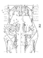
- the epicyclic gear train 16 is the type in which the intermediate gears 38 (planet gears, in the example) rotate relative to the rotational axis of the input gear 36. That is, the planet gears are permitted to rotate about the rotational axis of the input gear 36.
- the turbo-machinery 30 includes fixed structure 50 comprising a bearing compartment case 52 and a ring gear support 54. A ring gear 40 is coupled to the ring gear support 54.
- a torque frame 56 is integrated with the fan shaft 34 as a unitary structure.
- the torque frame 56 includes multiple shafts 58 integral with and extending from a base 61.
- the torque frame 56 includes five equally circumferentially spaced shafts 58 that correspondingly support five planet gears.
- the fan shaft 34, base 61 and shafts 58 of the torque frame 56 are unitary and formed by a one-piece structure, for example, by a forged steel structure. Other high strength metallic alloys, such titanium or nickel, may also be used.
- the torque frame 56 includes oil passages to which oil must be transferred from the fixed structure 50 as the torque frame 56 rotates.
- an oil passage 63 provides lubricating fluid to a spray bar 64 that delivers oil to output shaft bearings 62, which is supported by a front bearing housing 37.
- An oil transfer assembly 68 includes a transfer bearing 78 that is fixed and which mates to an oil baffle 66 that is secured to the rotating torque frame 56.
- a union 72 is affixed to the ring gear support 54 and receives lubricating fluid from a first transfer tube 74 that extends through the bearing compartment case 52.
- a second transfer tube 76 fluidly connects the union 72 to the transfer bearing 78, which is sealed to a collar 84 on the oil baffle 66.
- the oil baffle 66 includes a passage 80 that conveys lubricating fluid to an aperture 82 that is aligned with each shaft 58.
- a tube 100 fluidly connects the aperture 82 to a passage 70 in the shaft 58.
- Each shaft 58 includes a bearing assembly 60 for rotationally supporting its respective intermediate gear 38.
- the oil baffle 66 is secured to the torque frame 56 by fasteners 74.
- the oil baffle 66 is non-structural. That is, the oil baffle does not support the loads of the intermediate gears 38 as would a prior art carrier.
- the oil baffle 66 may be constructed from a considerably lower strength lighter weight material, such as an aluminum alloy or composite material.
- each shaft 58 includes an end 86 that supports a bearing assembly 60.
- the bearing assembly 60 includes a spherical bearing 88 supported in a race 90 on which the intermediate gear 38 is mounted.
- the ends 86 include a threaded portion that each receives a nut 91 securing the bearing assembly 60 to the shaft 58.
- the shaft 58, spherical bearing 88 and race 90 respectively include radially extending first, second and third passageways 92, 94, 96 that are aligned with one another to deliver lubricating fluid from the first passage 70 to bearing surfaces 98 provided between the race 90 and the intermediate gear 38.
- a recess 99 is provided in an outer diameter of the race 90 to increase lubrication at the bearing surfaces 98.
- the tube 100 includes a filter is arranged in a hole in the shaft 58 that provides a portion of the first passage 70.
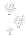
- the spherical bearing 88 includes an inner diameter 102 that is supported by the end 86.
- a convex surface 104 is provided on an outside of the spherical bearing 88 and mates with a corresponding concave surface 112 provided by an inner surface of the race 90 when fully assembled as illustrated in Figure 5B .
- the spherical bearing 88 includes a pin 106 that extends through both the inner diameter 102 and the convex surface 104 in the example illustrated.
- the pin 106 is received by notches 110, 114 respectively provided in the race 90 and end 86 to prevent rotation of the spherical bearing 88 about a bearing axis B ( Figure 5B ).
- the spherical bearing 88 permits angular movement of the bearing axis B relative to a shaft axis T ( Figure 3 ) provided by the shaft 58 during flexing of the shafts 58, which provides a near zero moment restraint.
- Figures 5A and 5B illustrate the assembly process of the bearing assembly 60.
- the spherical bearing 88 is inserted into slots 108 of the race 90, as shown in Figure 5A .
- the pin 106 is aligned with the notch 110 and the spherical bearing 88 is rotated to snap into engagement with the concave surface 112 with the pin 106 received in the notch 110.
- the second and third passageways 94, 96 are aligned with one another.
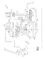
- Both the torque frame 56 and the oil baffle 66 provide internal lubrication features for supplying lubricating fluid, such as oil, to the gears of the epicyclic gear train 16.
- the passage 80 in the oil baffle 66 provides lubricating fluid to first and second passageways 130, 132.
- the first passageway 130 is fluidly connected to an oil passage 63 in the torque frame 56 via a tube 65.
- the first passageway 130 delivers oil to the spray bar 64.
- the second passageway 132 delivers lubricating fluid to a spray bar, which includes spray nozzles 134, provided integrally in the oil baffle 66.
- the second passageway 132 extends in a generally axial direction in the example shown, and the one or more spray nozzles 134 are transverse to the second passageway 132.
- the spray nozzles 134 are oriented to direct lubricating fluid radially inward at teeth 84 of the input gear 36.
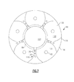
- the oil baffle 66 is illustrated in more detail in Figures 6 and 7 .
- the oil baffle 66 is provided by a body 116 having circumferentially spaced apart intermediate structures 118 axially extending from a wall 120.
- the intermediate structures 118 include the first passageway 130.
- the intermediate structures 118 define gear pockets 122 within which the intermediate gears 38 are received with the epicyclic gear train 16 fully assembled.
- Each gear pocket 122 includes the aperture 82 provided in the wall 120.
- the input gear 36 is received in a central opening 124 provided radially inward of the intermediate structures 118. Holes 126 are provided in the intermediate structures 118 and receive fasteners 128 to secure the oil baffle 66 to the torque frame 56, as illustrated in Figure 6 .
- the epicyclic gear train 16 is assembled by first installing the fixed structure into the bearing compartment case 52, such as the oil transfer assembly 68 and the ring gear 40.
- the input gear 36 is supported on the flex shaft 46.
- the intermediate gears 38 are mounted on the torque frame 56, and the fan shaft 34 is rotationally mounted in the front bearing housing 37 by bearings 62.
- the torque frame 56, with its intermediate gears 38, is inserted between the input gear 36 and the ring gear 40 such that the gears intermesh with one another.
- the front bearing housing 37 is secured to the fixed structure 50.
- the fan hub 35 is slid onto and secured to the fan shaft 34.
Landscapes
- Engineering & Computer Science (AREA)
- General Engineering & Computer Science (AREA)
- Mechanical Engineering (AREA)
- Chemical & Material Sciences (AREA)
- Combustion & Propulsion (AREA)
- General Details Of Gearings (AREA)
- Support Of The Bearing (AREA)
- Retarders (AREA)
Abstract
Description
- This disclosure relates to a fan drive gear system integrated carrier and torque frame.
- One type of gas turbine engine includes a fan drive gear system that is mechanically arranged between the turbo-machinery of the engine and a fan. The turbo-machinery is composed of two concentric shafts rotating at different speeds containing independent compressors and turbines. The turbo-machinery rotationally drives the fan, via the gear system, to move fluid through a nacelle, which divides the fluid flow into two streams. An inner stream supplies the turbo-machinery and the outer stream consists of fluid which bypasses the inner stream and is solely compressed and moved by the fan.
- Typically the fan drive gear system is provided by an epicyclic gear train and includes a centrally located input gear driven by the turbo-machinery, intermediate gears circumferentially arranged about and intermeshing with the input gear and a ring gear provided about and intermeshing the intermediate gears. Depending upon the configuration, either the intermediate gears or the ring gear rotationally drives the fan in response to rotation of the input gear.
- The intermediate gears are typically supported in a carrier by a journal extending between spaced apart walls of the carrier. The carrier is typically constructed from a high strength metallic alloy such as steel, titanium or nickel. The carrier is bolted to a torque frame, which is secured to fixed structure or rotating structure depending upon the particular type of gear system.
- One type of gear system for helicopter applications has been used which directly supports the intermediate gears on an integrated carrier and torque frame. This integrated torque frame includes shafts that directly support the intermediate gears in a cantilevered fashion by conventional rolling element bearings. This arrangement is subjected to vibrational stresses that may cause the integrated torque frame to fail.
- A fan gear drive system includes a torque frame having a base with integrated gear shafts circumferentially spaced relative to one another. A fan shaft is integrated with the base, and each shaft provides a shaft axis. A bearing assembly is mounted on each of the gear shafts and provides a bearing axis. The bearing assembly includes a spherical bearing configured to permit angular movement of the bearing axis relative to the shaft axis.
- A fan drive gear drive lubrication system includes a torque frame supporting multiple gears and has at least one lubrication passage. An oil baffle is secured to the torque frame and includes a central opening and multiple circumferentially spaced gear pockets arranged about the central opening to receive the multiple gears. The oil baffle includes at least one lubrication passageway in fluid communication with the lubrication passage. At least one tube extends between and fluidly interconnects the lubrication passage and passageway.
- A method of assembling a fan drive gear system includes the step of installing a spherical bearing into a race to provide a bearing assembly. The bearing assembly is mounted onto a shaft of a torque frame. The torque frame is supported in a front bearing housing by bearings. An intermediate gear is installed onto the bearing assembly.
- The disclosure can be further understood by reference to the following detailed description when considered in connection with the accompanying drawings wherein:
-
Figure 1 is a schematic cross-sectional view of an example gas turbine engine. -
Figure 2 is a cross-sectional view of an example fan drive gear system. -
Figure 3 is an enlarged cross-sectional view of a portion of the fan drive gear system illustrated inFigure 2 . -
Figure 4 is a perspective view of an example spherical bearing. -
Figure 5A is an elevational view of the spherical bearing ofFigure 4 inserted into a race in an assembly position. -
Figure 5B is an elevational view of the spherical bearing ofFigure 4 fully assembled into the race to provide a bearing assembly. -
Figure 6 is an enlarged cross-sectional view of another portion of the fan drive gear system illustrated inFigure 2 . -
Figure 7 is an elevational view of an example oil baffle used in the fan drive gear system and illustrated inFigures 2 and3 . - An example gas turbine engine 10 is schematically illustrated in
Figure 1 . The engine 10 includes turbo-machinery 30 having acompressor section 12 and a turbine section 14. The turbo-machinery 30 rotationally drives afan 32, which is arranged in abypass flow path 33, through anepicyclic gear train 16. The turbo-machinery 30 is housed within aninner nacelle 42. Flowexit guide vanes 31 arranged within the bypass flow path support the turbo-machinery 30 relative to a fan case, which is housed in afan nacelle 44. - A
low pressure compressor 18 and alow pressure turbine 20 are mounted on alow pressure spool 22. Ahigh pressure compressor 24 and ahigh pressure turbine 26 are mounted on ahigh pressure spool 28. Acombustor section 48 is arranged between thehigh pressure compressor 24 and thehigh pressure turbine 26. - The
low pressure spool 22 rotationally drives aflex shaft 46 to which an input gear 36 (sun gear) is mounted for rotation about an axis A. Intermediate gears 38 (in the example, star gears) are arranged circumferentially about and intermesh with theinput gear 36. Aring gear 40 surrounds and intermeshes with theintermediate gears 38. Either theintermediate gears 38 or thering gear 40 rotationally drives thefan shaft 34 depending upon the type of epicyclic gear train configuration. Afan hub 35 is supported by and rotationally affixed to thefan shaft 34. - One example
epicyclic gear train 16 is illustrated inFigure 2 . Theepicyclic gear train 16 is the type in which the intermediate gears 38 (planet gears, in the example) rotate relative to the rotational axis of theinput gear 36. That is, the planet gears are permitted to rotate about the rotational axis of theinput gear 36. The turbo-machinery 30 includesfixed structure 50 comprising abearing compartment case 52 and aring gear support 54. Aring gear 40 is coupled to thering gear support 54. - A
torque frame 56 is integrated with thefan shaft 34 as a unitary structure. Thetorque frame 56 includesmultiple shafts 58 integral with and extending from abase 61. In the example, thetorque frame 56 includes five equally circumferentially spacedshafts 58 that correspondingly support five planet gears. Thefan shaft 34,base 61 andshafts 58 of thetorque frame 56 are unitary and formed by a one-piece structure, for example, by a forged steel structure. Other high strength metallic alloys, such titanium or nickel, may also be used. - Referring to
Figure 3 , thetorque frame 56 includes oil passages to which oil must be transferred from thefixed structure 50 as thetorque frame 56 rotates. For example, anoil passage 63 provides lubricating fluid to aspray bar 64 that delivers oil to outputshaft bearings 62, which is supported by afront bearing housing 37. Anoil transfer assembly 68 includes a transfer bearing 78 that is fixed and which mates to anoil baffle 66 that is secured to the rotatingtorque frame 56. Aunion 72 is affixed to thering gear support 54 and receives lubricating fluid from afirst transfer tube 74 that extends through thebearing compartment case 52. Asecond transfer tube 76 fluidly connects theunion 72 to the transfer bearing 78, which is sealed to acollar 84 on theoil baffle 66. - The
oil baffle 66 includes apassage 80 that conveys lubricating fluid to anaperture 82 that is aligned with eachshaft 58. Atube 100 fluidly connects theaperture 82 to apassage 70 in theshaft 58. - Each
shaft 58 includes a bearingassembly 60 for rotationally supporting its respectiveintermediate gear 38. Theoil baffle 66 is secured to thetorque frame 56 byfasteners 74. Theoil baffle 66 is non-structural. That is, the oil baffle does not support the loads of theintermediate gears 38 as would a prior art carrier. As a result, theoil baffle 66 may be constructed from a considerably lower strength lighter weight material, such as an aluminum alloy or composite material. - Referring to
Figure 3 , eachshaft 58 includes anend 86 that supports a bearingassembly 60. The bearingassembly 60 includes aspherical bearing 88 supported in arace 90 on which theintermediate gear 38 is mounted. The ends 86 include a threaded portion that each receives anut 91 securing the bearingassembly 60 to theshaft 58. Theshaft 58,spherical bearing 88 andrace 90 respectively include radially extending first, second andthird passageways first passage 70 to bearingsurfaces 98 provided between therace 90 and theintermediate gear 38. Arecess 99 is provided in an outer diameter of therace 90 to increase lubrication at the bearing surfaces 98. In one example, thetube 100 includes a filter is arranged in a hole in theshaft 58 that provides a portion of thefirst passage 70. - Referring to
Figures 3-5B , thespherical bearing 88 includes aninner diameter 102 that is supported by theend 86. Aconvex surface 104 is provided on an outside of thespherical bearing 88 and mates with a correspondingconcave surface 112 provided by an inner surface of therace 90 when fully assembled as illustrated inFigure 5B . Thespherical bearing 88 includes apin 106 that extends through both theinner diameter 102 and theconvex surface 104 in the example illustrated. Thepin 106 is received bynotches race 90 and end 86 to prevent rotation of thespherical bearing 88 about a bearing axis B (Figure 5B ). Thespherical bearing 88 permits angular movement of the bearing axis B relative to a shaft axis T (Figure 3 ) provided by theshaft 58 during flexing of theshafts 58, which provides a near zero moment restraint. -
Figures 5A and 5B illustrate the assembly process of the bearingassembly 60. Thespherical bearing 88 is inserted intoslots 108 of therace 90, as shown inFigure 5A . Thepin 106 is aligned with thenotch 110 and thespherical bearing 88 is rotated to snap into engagement with theconcave surface 112 with thepin 106 received in thenotch 110. In this position, illustrated inFigure 5B , the second andthird passageways - Both the
torque frame 56 and theoil baffle 66 provide internal lubrication features for supplying lubricating fluid, such as oil, to the gears of theepicyclic gear train 16. Referring toFigure 6 , thepassage 80 in theoil baffle 66 provides lubricating fluid to first andsecond passageways 130, 132. Thefirst passageway 130 is fluidly connected to anoil passage 63 in thetorque frame 56 via atube 65. Thefirst passageway 130 delivers oil to thespray bar 64. The second passageway 132 delivers lubricating fluid to a spray bar, which includesspray nozzles 134, provided integrally in theoil baffle 66. The second passageway 132 extends in a generally axial direction in the example shown, and the one ormore spray nozzles 134 are transverse to the second passageway 132. In the example, thespray nozzles 134 are oriented to direct lubricating fluid radially inward atteeth 84 of theinput gear 36. - The
oil baffle 66 is illustrated in more detail inFigures 6 and7 . Theoil baffle 66 is provided by abody 116 having circumferentially spaced apartintermediate structures 118 axially extending from awall 120. Theintermediate structures 118 include thefirst passageway 130. Theintermediate structures 118 definegear pockets 122 within which theintermediate gears 38 are received with theepicyclic gear train 16 fully assembled. Eachgear pocket 122 includes theaperture 82 provided in thewall 120. Theinput gear 36 is received in acentral opening 124 provided radially inward of theintermediate structures 118.Holes 126 are provided in theintermediate structures 118 and receivefasteners 128 to secure theoil baffle 66 to thetorque frame 56, as illustrated inFigure 6 . - The
epicyclic gear train 16 is assembled by first installing the fixed structure into thebearing compartment case 52, such as theoil transfer assembly 68 and thering gear 40. Theinput gear 36 is supported on theflex shaft 46. The intermediate gears 38 are mounted on thetorque frame 56, and thefan shaft 34 is rotationally mounted in thefront bearing housing 37 bybearings 62. Thetorque frame 56, with itsintermediate gears 38, is inserted between theinput gear 36 and thering gear 40 such that the gears intermesh with one another. Thefront bearing housing 37 is secured to the fixedstructure 50. Thefan hub 35 is slid onto and secured to thefan shaft 34. - Although an example embodiment has been disclosed, a worker of ordinary skill in this art would recognize that certain modifications would come within the scope of the claims. For that reason, the following claims should be studied to determine their true scope and content.
Claims (15)
- A fan gear drive system comprising:a torque frame (56) comprising a base (61) with integrated gear shafts (58) circumferentially spaced relative to one another, each shaft providing a shaft axis (T);a fan shaft (34) integrated with the base (61); anda bearing assembly (60) mounted on each of the gear shafts (58) and providing a bearing axis (B), the bearing assembly including a spherical bearing (88) configured to permit angular movement of the bearing axis (B) relative to the shaft axis (T).
- The system according to claim 1, comprising a gear (38) supported on each bearing assembly (60) for rotation about the bearing axis (B), an input gear (36) located radially inward from and intermeshing with intermediate gears (38) supported on the gear shafts (58), and a ring gear (40) arranged about and intermeshing with the intermediate gears (38), the input gear (36) supported by an input shaft (46), and a fixed structure (50) supporting the ring gear (40).
- The system according to claim 1 or 2, wherein the bearing assembly (60) includes a race (90) supporting the gear (38), and the spherical bearing (88) is received by the race, and a pin (106) configured to prevent relative rotation between the race (90), spherical bearing (88) and the shaft (58) about the shaft axis (T).
- The system according to claim 2 or claim 3 when dependent on claim 2, wherein the torque frame (56) includes a first passage (70) provided through the shaft (58) and configured to provide lubricating fluid to the gears (38), and the bearing assembly (60) includes at least one passageway (92,94,96) extending through each of the spherical bearing (88) and the race (90) and in fluid communication with the passage (70).
- The system according to claim 4, comprising an oil baffle (66) supported by the torque frame (56) and in fluid communication with the first passage (70), the oil baffle including a second passage (80) configured to receive lubricating fluid from an oil transfer assembly (68) during rotation of the torque frame (56) relative to the fixed structure (50).
- The system according to claim 5, comprising a tube (100) fluidly connecting the first and second passages (70,80), and the oil baffle (66) including third and fourth passages (132,130) respectively fluidly connecting to first and second spray bars (134,64); preferably wherein the first spray bar (134) is provided in the oil baffle (66) and is configured to direct lubricating fluid at teeth (84) of at least one of the input gear (36) and the intermediate gears (38), and the second spray bar (64) is supported by the torque frame and in fluid communication with a fifth passage (65) in the torque frame (56) that is in fluid communication with the fourth passage (130).
- The system according to claim 5 or 6, wherein the torque frame (56) is constructed from a high strength metallic alloy, and the oil baffle (66) is constructed from a lower strength lighter weight alloy than the high strength metallic alloy.
- A fan drive gear drive lubrication system comprising:a torque frame (56) supporting multiple gears (38) and including at least one lubrication passage (70);an oil baffle (66) secured to the torque frame (56) and including a central opening (124) and multiple circumferentially spaced gear pockets (122) arranged about the central opening and receiving the multiple gears (38), the oil baffle (66) including at least one lubrication passageway (80) in fluid communication with the lubrication passage (70); andat least one tube (100) extending between and fluidly interconnecting the lubrication passage (70) and passageway (80).
- The system according to claim 8, wherein the torque frame(56) includes a base (61) with an integrated fan shaft (34) and integrated gear shafts (58) circumferentially spaced relative to one another and supporting the multiple gears (38); preferably wherein a bearing assembly (60) is mounted on each shaft (58) and includes a race (90) receiving a spherical bearing (88), and at least one passageway (92,94,96) extending through each of the spherical bearing (88) and the race (90) and in fluid communication with the lubrication passage (70).
- The system according to claim 8 or 9, wherein the oil baffle (66) includes a passage (80) configured to receive lubricating fluid from an oil transfer assembly (68), the passage in fluid communication with multiple passages in each of the oil baffle (66) and the torque frame (56) for conveying the lubricating fluid to multiple spray bars (64;134); and/or wherein the oil baffle (66) includes an integrated spray bar (132) configured to direct lubricating fluid at teeth (84) of a gear (36).
- A method of assembling a fan drive gear system comprising the steps of:installing a spherical bearing (88) into a race (90) to provide a bearing assembly (60);mounting the bearing assembly (60) onto a shaft (58) of a torque frame (56);supporting the torque frame (56) in a front bearing housing (37) by bearings (62); andinstalling an intermediate gear (38) onto the bearing assembly (60).
- The method according to claim 11, wherein the installing step includes inserting a spherical bearing (88) into slots (108) in the race (90) and rotating the spherical bearing and the race relative to one another to seat the spherical bearing within the race, and the installing step includes aligning first and second lubrication passageways (94,96) provided in the spherical bearing (88) and race (90) with one another.
- The method according to claim 11 or 12, comprising the steps of supporting an input shaft on a flex shaft (46), securing a ring gear (40) onto a fixed structure (50), and inserting the intermediate gear (38) and torque frame (56) between the ring (40) and input gears (36) in intermeshing relationship.
- The method according to claim 13, comprising the steps of securing the front bearing housing (37) to the fixed structure (50), and securing a fan hub (35) onto a fan shaft (34).
- The method according to claim 13 or 14, comprising the steps of supporting an oil transfer assembly (68) on the fixed structure (50), and the inserting step includes mating an oil baffle (66) with the oil transfer assembly (68); preferably comprising the step of securing the oil baffle (66) to the torque frame (56) and fluidly connecting lubrication passages in the torque frame (70) to lubrication passageways (80) in the oil baffle; wherein preferably the lubrication passageways (80) include a spray bar (134) facing an input gear (36).
Priority Applications (1)
| Application Number | Priority Date | Filing Date | Title |
|---|---|---|---|
| EP19185596.4A EP3572630B1 (en) | 2011-04-27 | 2012-04-27 | Fan drive gear drive lubrication system |
Applications Claiming Priority (1)
| Application Number | Priority Date | Filing Date | Title |
|---|---|---|---|
| US13/095,308 US8777793B2 (en) | 2011-04-27 | 2011-04-27 | Fan drive planetary gear system integrated carrier and torque frame |
Related Child Applications (2)
| Application Number | Title | Priority Date | Filing Date |
|---|---|---|---|
| EP19185596.4A Division-Into EP3572630B1 (en) | 2011-04-27 | 2012-04-27 | Fan drive gear drive lubrication system |
| EP19185596.4A Division EP3572630B1 (en) | 2011-04-27 | 2012-04-27 | Fan drive gear drive lubrication system |
Publications (3)
| Publication Number | Publication Date |
|---|---|
| EP2518279A2 true EP2518279A2 (en) | 2012-10-31 |
| EP2518279A3 EP2518279A3 (en) | 2018-06-27 |
| EP2518279B1 EP2518279B1 (en) | 2019-08-21 |
Family
ID=46045903
Family Applications (2)
| Application Number | Title | Priority Date | Filing Date |
|---|---|---|---|
| EP19185596.4A Active EP3572630B1 (en) | 2011-04-27 | 2012-04-27 | Fan drive gear drive lubrication system |
| EP12166086.4A Active EP2518279B1 (en) | 2011-04-27 | 2012-04-27 | Fan drive planetary gear system integrated carrier and torque frame |
Family Applications Before (1)
| Application Number | Title | Priority Date | Filing Date |
|---|---|---|---|
| EP19185596.4A Active EP3572630B1 (en) | 2011-04-27 | 2012-04-27 | Fan drive gear drive lubrication system |
Country Status (2)
| Country | Link |
|---|---|
| US (2) | US8777793B2 (en) |
| EP (2) | EP3572630B1 (en) |
Cited By (6)
| Publication number | Priority date | Publication date | Assignee | Title |
|---|---|---|---|---|
| EP3001072A1 (en) * | 2014-09-08 | 2016-03-30 | United Technologies Corporation | Oil transfer bearing and oil transfer method |
| EP3002433A1 (en) * | 2014-10-03 | 2016-04-06 | Rolls-Royce Deutschland Ltd & Co KG | Geared architecture for a gas turbine |
| EP3002434A1 (en) * | 2014-10-03 | 2016-04-06 | Rolls-Royce plc | Geared architecture for a gas turbine with squeeze film damper |
| EP3392515A1 (en) * | 2017-04-19 | 2018-10-24 | Rolls-Royce plc | Bearing arrangement |
| US10393068B2 (en) | 2015-09-18 | 2019-08-27 | Rolls-Royce Plc | Shafting arrangement for a gas turbine engine |
| EP3705705A1 (en) | 2019-03-07 | 2020-09-09 | Safran Aircraft Engines | Mechanical gear of an aircraft turbine engine |
Families Citing this family (38)
| Publication number | Priority date | Publication date | Assignee | Title |
|---|---|---|---|---|
| US8900083B2 (en) | 2011-04-27 | 2014-12-02 | United Technologies Corporation | Fan drive gear system integrated carrier and torque frame |
| ITTO20111007A1 (en) * | 2011-11-03 | 2013-05-04 | Avio Spa | EPICYCLOIDAL ROTISM |
| US9249685B2 (en) * | 2012-12-17 | 2016-02-02 | United Technologies Corporation | Fan drive gear system assembly guide |
| US10267232B2 (en) | 2013-02-06 | 2019-04-23 | United Technologies Corporation | Oil baffles in carrier for a fan drive gear system |
| WO2014137571A1 (en) | 2013-03-04 | 2014-09-12 | United Technologies Corporation | Fan drive gear system spline oil lubrication scheme |
| EP3699413B1 (en) | 2013-07-07 | 2022-12-21 | Raytheon Technologies Corporation | Fan drive gear system manifold radial tube filters |
| US10533522B2 (en) | 2013-08-21 | 2020-01-14 | United Technologies Corporation | Load balanced journal bearing pin |
| US9726083B2 (en) | 2013-08-21 | 2017-08-08 | United Technologies Corporation | Load balanced journal bearing pin for planetary gear |
| FR3010449B1 (en) * | 2013-09-06 | 2015-09-25 | Snecma | ROTARY ASSEMBLY COMPRISING A TRANSMISSION MEMBER AND AN OIL DISTRIBUTION SYSTEM |
| FR3013385B1 (en) * | 2013-11-21 | 2015-11-13 | Snecma | PRE-SEALED SPEAKER DURING MODULAR DISASSEMBLY OF A REDUCING TURBOREACTOR |
| EP3524796B8 (en) * | 2013-12-30 | 2020-12-16 | Raytheon Technologies Corporation | Fan drive gear system including a two-piece fan shaft with lubricant transfer leakage recapture and corresponding assembly method |
| US10280843B2 (en) | 2014-03-07 | 2019-05-07 | United Technologies Corporation | Geared turbofan with integral front support and carrier |
| US9869190B2 (en) | 2014-05-30 | 2018-01-16 | General Electric Company | Variable-pitch rotor with remote counterweights |
| DE102014114043A1 (en) * | 2014-09-26 | 2016-03-31 | Rolls-Royce Deutschland Ltd & Co Kg | Aero engine with a compressor device |
| US10072510B2 (en) | 2014-11-21 | 2018-09-11 | General Electric Company | Variable pitch fan for gas turbine engine and method of assembling the same |
| US10100653B2 (en) | 2015-10-08 | 2018-10-16 | General Electric Company | Variable pitch fan blade retention system |
| US10281025B2 (en) | 2015-10-19 | 2019-05-07 | United Technologies Corporation | Fixed support and oil collector system for ring gear |
| US10267334B2 (en) * | 2016-08-01 | 2019-04-23 | United Technologies Corporation | Annular heatshield |
| EP3306116B1 (en) * | 2016-10-06 | 2020-12-16 | Rolls-Royce Deutschland Ltd & Co KG | Geared turbofan engine and sun shaft for driving sun gear of planetary gearbox |
| US10239401B2 (en) | 2017-01-23 | 2019-03-26 | Auburn Gear, Llc | Electric motor and gearing assembly |
| FR3073915B1 (en) * | 2017-11-17 | 2019-10-25 | Safran Transmission Systems | TURBOMACHINE PLANETARY OR EPICYCLOIDAL TRAIN SPEED CAGE |
| US10724445B2 (en) | 2018-01-03 | 2020-07-28 | Raytheon Technologies Corporation | Method of assembly for fan drive gear system with rotating carrier |
| DE102018106488A1 (en) * | 2018-03-20 | 2019-09-26 | Rolls-Royce Deutschland Ltd & Co Kg | Gas turbine engine and method of introducing oil into a transmission assembly |
| US11225912B2 (en) * | 2018-04-20 | 2022-01-18 | Pratt & Whitney Canada Corp. | Gear assembly for coaxial shafts in gas turbine engine |
| FR3084428B1 (en) * | 2018-07-26 | 2020-09-11 | Safran Trans Systems | PLANETARY OR EPICYCLOIDAL GEAR REDUCER CAGE FOR TURBOMACHINE |
| CN112345343B (en) * | 2020-11-26 | 2025-06-10 | 中国人民解放军第六九O五工厂 | Overhead wind load torque generator |
| FR3118646B1 (en) * | 2021-01-05 | 2024-02-16 | Safran Trans Systems | SATELLITE CARRIER FOR A MECHANICAL AIRCRAFT TURBOMACHINE REDUCER |
| US11674435B2 (en) | 2021-06-29 | 2023-06-13 | General Electric Company | Levered counterweight feathering system |
| US11795964B2 (en) | 2021-07-16 | 2023-10-24 | General Electric Company | Levered counterweight feathering system |
| US11814975B2 (en) | 2021-08-20 | 2023-11-14 | Pratt & Whitney Canada Corp. | Feed circuit with slot(s) at interface between journal bearing and rotor |
| US11821364B2 (en) | 2021-08-20 | 2023-11-21 | Pratt & Whitney Canada Corp. | Shaped cavity at interface between journal bearing and rotor |
| US11680525B2 (en) * | 2021-08-20 | 2023-06-20 | Pratt & Whitney Canada Corp. | Lubricant filter for a turbine engine |
| US11598407B1 (en) | 2022-02-16 | 2023-03-07 | Pratt & Whitney Canada Corp. | Epicyclic gear train of aircraft powerplant |
| US12359617B2 (en) * | 2023-08-04 | 2025-07-15 | Rtx Corporation | Axial transfer bearing |
| US12188417B1 (en) * | 2023-09-20 | 2025-01-07 | Rtx Corporation | Rotating carrier oil manifold |
| US12135076B1 (en) | 2023-09-29 | 2024-11-05 | Rtx Corporation | Fluid device(s) for supporting rotating structure(s) of a turbine engine |
| US12292107B2 (en) | 2023-09-29 | 2025-05-06 | Rtx Corporation | Fluid damper for turbine engine geartrain assembly |
| US12188551B1 (en) | 2023-09-29 | 2025-01-07 | Rtx Corporation | Reduced clearance interface between a fluid device and a rotating structure for a geartrain |
Family Cites Families (130)
| Publication number | Priority date | Publication date | Assignee | Title |
|---|---|---|---|---|
| US1586309A (en) * | 1924-02-21 | 1926-05-25 | Hult Carl Alrik | Planet gear |
| BE436044A (en) * | 1938-03-10 | |||
| US2672726A (en) | 1950-09-19 | 1954-03-23 | Bell Aircraft Corp | Ducted fan jet aircraft engine |
| US2798360A (en) | 1950-10-06 | 1957-07-09 | Gen Motors Corp | Ducted fan type jet propulsion engine |
| US2749778A (en) * | 1952-03-11 | 1956-06-12 | Farrel Birmingham Co Inc | Articulated planetary gearing |
| US2850337A (en) | 1954-05-31 | 1958-09-02 | Mccalium Neville Clyde | Bearings |
| GB798273A (en) * | 1955-11-04 | 1958-07-16 | Gen Motors Corp | Improvements relating to planetary gearing |
| US3227006A (en) * | 1963-01-14 | 1966-01-04 | Bell Aerospace Corp | Power transmitting gear train |
| US3257869A (en) * | 1963-09-20 | 1966-06-28 | Pennsalt Chemicals Corp | Planetary gearing |
| US3352178A (en) * | 1965-11-15 | 1967-11-14 | Gen Motors Corp | Planetary gearing |
| GB1085619A (en) | 1966-03-09 | 1967-10-04 | Rolls Royce | Gas turbine engine |
| FR1555814A (en) | 1967-12-12 | 1969-01-31 | ||
| US3635103A (en) * | 1968-12-24 | 1972-01-18 | Siai Marchetti Spa | Planetary reduction gearing |
| US3680309A (en) | 1969-09-25 | 1972-08-01 | Garrett Corp | Two-spool auxiliary power unit and control means |
| US3638428A (en) | 1970-05-04 | 1972-02-01 | Gen Electric | Bypass valve mechanism |
| US3761042A (en) | 1970-05-16 | 1973-09-25 | Secr Defence | Gas turbine engine |
| US3673802A (en) | 1970-06-18 | 1972-07-04 | Gen Electric | Fan engine with counter rotating geared core booster |
| US3738719A (en) | 1970-08-04 | 1973-06-12 | Snecma | Ball bearing |
| SE345892B (en) | 1970-10-26 | 1972-06-12 | Defibrator Ab | |
| GB1318629A (en) | 1970-11-21 | 1973-05-31 | Secr Defence | Gas turbine engine |
| US3747343A (en) | 1972-02-10 | 1973-07-24 | United Aircraft Corp | Low noise prop-fan |
| US3792586A (en) | 1973-01-22 | 1974-02-19 | Avco Corp | Bearing assembly systems |
| US3896615A (en) | 1973-02-08 | 1975-07-29 | United Aircraft Corp | Gas turbine engine for subsonic flight |
| US3925979A (en) | 1973-10-29 | 1975-12-16 | Gen Electric | Anti-icing system for a gas turbine engine |
| US3971208A (en) | 1974-04-01 | 1976-07-27 | The Garrett Corporation | Gas turbine fuel control |
| DE7411435U (en) * | 1974-04-02 | 1974-06-27 | Hurth C Maschinen Und Zahnradfabrik | GEAR TRANSMISSION |
| US4055946A (en) | 1976-03-29 | 1977-11-01 | United Technologies Corporation | Twin-spool gas turbine power plant with means to spill compressor interstage airflow |
| US4084861A (en) | 1976-11-11 | 1978-04-18 | United Technologies Corporation | Thrust bearing damping means |
| US4251987A (en) | 1979-08-22 | 1981-02-24 | General Electric Company | Differential geared engine |
| FR2518650B1 (en) | 1981-12-22 | 1986-05-30 | Snecma | DEVICE FOR CONTROLLING THE GAMES OF A MULTI-BODY TURBOMACHINE INTER-SHAFT BEARING |
| DE3267847D1 (en) * | 1982-01-18 | 1986-01-16 | Mavilor Syst Sa | Transmission with orbital motion gears |
| US4452037A (en) | 1982-04-16 | 1984-06-05 | Avco Corporation | Air purge system for gas turbine engine |
| US4523864A (en) | 1984-04-27 | 1985-06-18 | United Technologies Corporation | Tandem bearing construction |
| US4704862A (en) | 1985-05-29 | 1987-11-10 | United Technologies Corporation | Ducted prop engine |
| JPH0351546Y2 (en) | 1986-01-07 | 1991-11-06 | ||
| US4687346A (en) | 1986-09-02 | 1987-08-18 | United Technologies Corporation | Low profile bearing support structure |
| GB8630754D0 (en) | 1986-12-23 | 1987-02-04 | Rolls Royce Plc | Turbofan gas turbine engine |
| US4782658A (en) | 1987-05-07 | 1988-11-08 | Rolls-Royce Plc | Deicing of a geared gas turbine engine |
| IT1219755B (en) | 1987-05-14 | 1990-05-24 | Skf Gmbh | DRIVE DEVICE FOR PUMPS OR SIMILAR |
| US4867655A (en) | 1988-03-14 | 1989-09-19 | United Technologies Corporation | Variable stiffness oil film damper |
| US4916894A (en) | 1989-01-03 | 1990-04-17 | General Electric Company | High bypass turbofan engine having a partially geared fan drive turbine |
| US4951461A (en) | 1989-03-20 | 1990-08-28 | General Electric Company | Power turbine support arrangement |
| US4952076A (en) | 1989-07-21 | 1990-08-28 | United Technologies Corporation | Fluid damper for thrust bearing |
| US4981415A (en) | 1989-08-16 | 1991-01-01 | United Technologies Corporation | Support for oil film dampers |
| US5051005A (en) | 1990-08-17 | 1991-09-24 | The Torrington Company | Variable preload bearing apparatus |
| US5127794A (en) | 1990-09-12 | 1992-07-07 | United Technologies Corporation | Compressor case with controlled thermal environment |
| US5102379A (en) | 1991-03-25 | 1992-04-07 | United Technologies Corporation | Journal bearing arrangement |
| US5687561A (en) | 1991-09-17 | 1997-11-18 | Rolls-Royce Plc | Ducted fan gas turbine engine accessory drive |
| US5174525A (en) | 1991-09-26 | 1992-12-29 | General Electric Company | Structure for eliminating lift load bending in engine core of turbofan |
| IT1250861B (en) | 1991-11-12 | 1995-04-21 | Fiat Avio Spa | EPICYCLOIDAL SPEED REDUCER SUITABLE TO BE INSERTED IN THE TRANSMISSION BETWEEN A GAS TURBINE AND THE AIR COMPRESSOR OF AN AIRCRAFT ENGINE. |
| FR2698911B1 (en) | 1992-12-09 | 1995-01-06 | Snecma | Aircraft engine layout. |
| US5466198A (en) | 1993-06-11 | 1995-11-14 | United Technologies Corporation | Geared drive system for a bladed propulsor |
| US5553449A (en) | 1993-12-21 | 1996-09-10 | United Technologies Corporation | Method of operating a gas turbine engine powerplant for an aircraft |
| US5380155A (en) | 1994-03-01 | 1995-01-10 | United Technologies Corporation | Compressor stator assembly |
| US5433674A (en) | 1994-04-12 | 1995-07-18 | United Technologies Corporation | Coupling system for a planetary gear train |
| US5622438A (en) | 1995-07-12 | 1997-04-22 | United Technologies Corporation | Fire resistant bearing compartment cover |
| GB9602130D0 (en) | 1996-02-02 | 1996-04-03 | Rolls Royce Plc | Improved method of combining ducted fan gas turbine engine modules and aircraft structure |
| US5809772A (en) | 1996-03-29 | 1998-09-22 | General Electric Company | Turbofan engine with a core driven supercharged bypass duct |
| US5806303A (en) | 1996-03-29 | 1998-09-15 | General Electric Company | Turbofan engine with a core driven supercharged bypass duct and fixed geometry nozzle |
| US5867980A (en) | 1996-12-17 | 1999-02-09 | General Electric Company | Turbofan engine with a low pressure turbine driven supercharger in a bypass duct operated by a fuel rich combustor and an afterburner |
| US5791789A (en) | 1997-04-24 | 1998-08-11 | United Technologies Corporation | Rotor support for a turbine engine |
| US6158210A (en) | 1998-12-03 | 2000-12-12 | General Electric Company | Gear driven booster |
| US6203273B1 (en) | 1998-12-22 | 2001-03-20 | United Technologies Corporation | Rotary machine |
| US6148518A (en) | 1998-12-22 | 2000-11-21 | United Technologies Corporation | Method of assembling a rotary machine |
| US6082959A (en) | 1998-12-22 | 2000-07-04 | United Technologies Corporation | Method and apparatus for supporting a rotatable shaft within a gas turbine engine |
| US6223616B1 (en) | 1999-12-22 | 2001-05-01 | United Technologies Corporation | Star gear system with lubrication circuit and lubrication method therefor |
| US6338609B1 (en) | 2000-02-18 | 2002-01-15 | General Electric Company | Convex compressor casing |
| US6439772B1 (en) | 2000-12-01 | 2002-08-27 | General Electric Company | Method and apparatus for supporting rotor assembly bearings |
| US6464401B1 (en) | 2001-01-26 | 2002-10-15 | United Technologies Corporation | High load capacity bi-directional tapered roller bearing |
| SE518489C2 (en) | 2001-02-01 | 2002-10-15 | Skf Ab | Precision spindle assembly for low friction function |
| US6663530B2 (en) | 2001-12-14 | 2003-12-16 | Pratt & Whitney Canada Corp. | Zero twist carrier |
| EP1474616B1 (en) * | 2002-02-15 | 2006-10-11 | Brueninghaus Hydromatik Gmbh | Rotation-slide bearing |
| US6619030B1 (en) | 2002-03-01 | 2003-09-16 | General Electric Company | Aircraft engine with inter-turbine engine frame supported counter rotating low pressure turbine rotors |
| US6732502B2 (en) | 2002-03-01 | 2004-05-11 | General Electric Company | Counter rotating aircraft gas turbine engine with high overall pressure ratio compressor |
| JP3927886B2 (en) | 2002-08-09 | 2007-06-13 | 本田技研工業株式会社 | Axial flow compressor |
| GB0311663D0 (en) | 2003-05-21 | 2003-06-25 | Rolls Royce Plc | Aeroengine intake |
| US6942451B1 (en) | 2003-06-03 | 2005-09-13 | Hamilton Sundstrand Corporation | Damping system for an expendable gas turbine engine |
| JP4008390B2 (en) | 2003-07-30 | 2007-11-14 | 三菱重工業株式会社 | pump |
| FR2866074B1 (en) | 2004-02-11 | 2006-04-28 | Snecma Moteurs | ARCHITECTURE OF A TURBOJET ENGINE HAVING A DOUBLE BLOWER FORWARD |
| US7033301B2 (en) * | 2004-02-26 | 2006-04-25 | Ford Global Technologies, Llc | Planet pinion carrier assembly for Ravigneaux gearset |
| FR2867229B1 (en) | 2004-03-05 | 2006-07-28 | Snecma Moteurs | TURBOMACHINE BEARING BEARING WITH REDUCED SIZE |
| GB0411850D0 (en) | 2004-05-27 | 2004-06-30 | Rolls Royce Plc | Spacing arrangement |
| FR2872485B1 (en) | 2004-07-05 | 2006-09-15 | Snecma Moteurs Sa | STIFFENER FOR LOW PRESSURE COMPRESSOR OF AN AIRCRAFT ENGINE |
| EP1630356A1 (en) | 2004-08-25 | 2006-03-01 | Siemens Aktiengesellschaft | Fluid injection in a gas turbine during a cooling down period |
| US7334392B2 (en) | 2004-10-29 | 2008-02-26 | General Electric Company | Counter-rotating gas turbine engine and method of assembling same |
| US7883315B2 (en) | 2004-12-01 | 2011-02-08 | United Technologies Corporation | Seal assembly for a fan rotor of a tip turbine engine |
| US7309210B2 (en) | 2004-12-17 | 2007-12-18 | United Technologies Corporation | Turbine engine rotor stack |
| US20060196164A1 (en) | 2005-03-03 | 2006-09-07 | Donohue Thomas F | Dual mode turbo engine |
| DE102005018139A1 (en) | 2005-04-20 | 2006-10-26 | Mtu Aero Engines Gmbh | Jet engine |
| US7500365B2 (en) | 2005-05-05 | 2009-03-10 | United Technologies Corporation | Accessory gearbox |
| BE1016742A3 (en) * | 2005-08-31 | 2007-05-08 | Hansen Transmissions Int | A PLANETARY GEAR CONSTRUCTION. |
| US7493753B2 (en) | 2005-10-19 | 2009-02-24 | General Electric Company | Gas turbine engine assembly and methods of assembling same |
| US7490460B2 (en) | 2005-10-19 | 2009-02-17 | General Electric Company | Gas turbine engine assembly and methods of assembling same |
| US7603844B2 (en) | 2005-10-19 | 2009-10-20 | General Electric Company | Gas turbine engine assembly and methods of assembling same |
| US7752836B2 (en) | 2005-10-19 | 2010-07-13 | General Electric Company | Gas turbine assembly and methods of assembling same |
| US7730715B2 (en) | 2006-05-15 | 2010-06-08 | United Technologies Corporation | Fan frame |
| US8667688B2 (en) | 2006-07-05 | 2014-03-11 | United Technologies Corporation | Method of assembly for gas turbine fan drive gear system |
| US8585538B2 (en) | 2006-07-05 | 2013-11-19 | United Technologies Corporation | Coupling system for a star gear train in a gas turbine engine |
| US7704178B2 (en) | 2006-07-05 | 2010-04-27 | United Technologies Corporation | Oil baffle for gas turbine fan drive gear system |
| US7694505B2 (en) | 2006-07-31 | 2010-04-13 | General Electric Company | Gas turbine engine assembly and method of assembling same |
| US7658074B2 (en) | 2006-08-31 | 2010-02-09 | United Technologies Corporation | Mid-mount centerbody heat shield for turbine engine fuel nozzle |
| EP2064434B1 (en) | 2006-10-12 | 2012-06-27 | United Technologies Corporation | Operational line management of low pressure compressor in a turbofan engine |
| US7832193B2 (en) | 2006-10-27 | 2010-11-16 | General Electric Company | Gas turbine engine assembly and methods of assembling same |
| US7921634B2 (en) | 2006-10-31 | 2011-04-12 | General Electric Company | Turbofan engine assembly and method of assembling same |
| US7905083B2 (en) | 2006-10-31 | 2011-03-15 | General Electric Company | Turbofan engine assembly and method of assembling same |
| US7882693B2 (en) | 2006-11-29 | 2011-02-08 | General Electric Company | Turbofan engine assembly and method of assembling same |
| US7716914B2 (en) | 2006-12-21 | 2010-05-18 | General Electric Company | Turbofan engine assembly and method of assembling same |
| US7877980B2 (en) | 2006-12-28 | 2011-02-01 | General Electric Company | Convertible gas turbine engine |
| US9957918B2 (en) | 2007-08-28 | 2018-05-01 | United Technologies Corporation | Gas turbine engine front architecture |
| US8075261B2 (en) | 2007-09-21 | 2011-12-13 | United Technologies Corporation | Gas turbine engine compressor case mounting arrangement |
| US8277174B2 (en) | 2007-09-21 | 2012-10-02 | United Technologies Corporation | Gas turbine engine compressor arrangement |
| US7955046B2 (en) | 2007-09-25 | 2011-06-07 | United Technologies Corporation | Gas turbine engine front architecture modularity |
| US9605560B2 (en) | 2007-11-13 | 2017-03-28 | United Technolgies Corporation | Fan shaft retention |
| US8162605B2 (en) | 2008-01-14 | 2012-04-24 | United Technologies Corporation | Gas turbine engine case |
| US8128021B2 (en) | 2008-06-02 | 2012-03-06 | United Technologies Corporation | Engine mount system for a turbofan gas turbine engine |
| US8863529B2 (en) | 2008-12-31 | 2014-10-21 | Rolls-Royce North American Technologies, Inc. | Variable pressure ratio compressor |
| US20100170224A1 (en) | 2009-01-08 | 2010-07-08 | General Electric Company | Plasma enhanced booster and method of operation |
| GB0905110D0 (en) | 2009-03-25 | 2009-05-06 | Rolls Royce Plc | Bearing arrangement |
| US8561411B2 (en) | 2009-09-02 | 2013-10-22 | United Technologies Corporation | Air particle separator for a gas turbine engine |
| US8439637B2 (en) | 2009-11-20 | 2013-05-14 | United Technologies Corporation | Bellows preload and centering spring for a fan drive gear system |
| US9784181B2 (en) | 2009-11-20 | 2017-10-10 | United Technologies Corporation | Gas turbine engine architecture with low pressure compressor hub between high and low rotor thrust bearings |
| US8511987B2 (en) | 2009-11-20 | 2013-08-20 | United Technologies Corporation | Engine bearing support |
| US8672801B2 (en) | 2009-11-30 | 2014-03-18 | United Technologies Corporation | Mounting system for a planetary gear train in a gas turbine engine |
| US20110219781A1 (en) | 2010-03-10 | 2011-09-15 | Daniel Benjamin | Gas turbine engine with tie shaft for axial high pressure compressor rotor |
| JP4785976B1 (en) | 2010-04-13 | 2011-10-05 | 川崎重工業株式会社 | Planetary gear set |
| US8900083B2 (en) | 2011-04-27 | 2014-12-02 | United Technologies Corporation | Fan drive gear system integrated carrier and torque frame |
| US8899916B2 (en) | 2011-08-30 | 2014-12-02 | United Technologies Corporation | Torque frame and asymmetric journal bearing for fan drive gear system |
| US8402741B1 (en) | 2012-01-31 | 2013-03-26 | United Technologies Corporation | Gas turbine engine shaft bearing configuration |
| US20130319006A1 (en) | 2012-05-31 | 2013-12-05 | Francis Parnin | Direct feed auxiliary oil system for geared turbofan engine |
| US9328818B2 (en) | 2012-09-21 | 2016-05-03 | United Technologies Corporation | Gear carrier flex mount lubrication |
-
2011
- 2011-04-27 US US13/095,308 patent/US8777793B2/en active Active
-
2012
- 2012-04-27 EP EP19185596.4A patent/EP3572630B1/en active Active
- 2012-04-27 EP EP12166086.4A patent/EP2518279B1/en active Active
-
2014
- 2014-05-29 US US14/290,576 patent/US9068629B2/en active Active
Non-Patent Citations (1)
| Title |
|---|
| None |
Cited By (12)
| Publication number | Priority date | Publication date | Assignee | Title |
|---|---|---|---|---|
| EP3001072A1 (en) * | 2014-09-08 | 2016-03-30 | United Technologies Corporation | Oil transfer bearing and oil transfer method |
| US9695710B2 (en) | 2014-09-08 | 2017-07-04 | United Technologies Corporation | Oil transfer bearing |
| EP3002433A1 (en) * | 2014-10-03 | 2016-04-06 | Rolls-Royce Deutschland Ltd & Co KG | Geared architecture for a gas turbine |
| EP3002434A1 (en) * | 2014-10-03 | 2016-04-06 | Rolls-Royce plc | Geared architecture for a gas turbine with squeeze film damper |
| US10151249B2 (en) | 2014-10-03 | 2018-12-11 | Rolls-Royce Deutschland Ltd & Co Kg | Gas turbine architecture |
| US10202905B2 (en) | 2014-10-03 | 2019-02-12 | Rolls-Royce Deutschland Ltd & Co Kg | Gas turbine architecture |
| US10393068B2 (en) | 2015-09-18 | 2019-08-27 | Rolls-Royce Plc | Shafting arrangement for a gas turbine engine |
| EP3392515A1 (en) * | 2017-04-19 | 2018-10-24 | Rolls-Royce plc | Bearing arrangement |
| US10927891B2 (en) | 2017-04-19 | 2021-02-23 | Rolls-Royce Plc | Bearing arrangement |
| EP3705705A1 (en) | 2019-03-07 | 2020-09-09 | Safran Aircraft Engines | Mechanical gear of an aircraft turbine engine |
| FR3093550A1 (en) * | 2019-03-07 | 2020-09-11 | Safran Aircraft Engines | AIRCRAFT TURBOMACHINE MECHANICAL REDUCER |
| US11396846B2 (en) | 2019-03-07 | 2022-07-26 | Safran Aircraft Engines | Aircraft turbine engine mechanical reduction gear |
Also Published As
| Publication number | Publication date |
|---|---|
| EP2518279B1 (en) | 2019-08-21 |
| EP3572630A3 (en) | 2020-03-18 |
| EP2518279A3 (en) | 2018-06-27 |
| US8777793B2 (en) | 2014-07-15 |
| US20120277055A1 (en) | 2012-11-01 |
| EP3572630A2 (en) | 2019-11-27 |
| US20140274531A1 (en) | 2014-09-18 |
| US9068629B2 (en) | 2015-06-30 |
| EP3572630B1 (en) | 2021-07-28 |
Similar Documents
| Publication | Publication Date | Title |
|---|---|---|
| US8777793B2 (en) | Fan drive planetary gear system integrated carrier and torque frame | |
| US8900083B2 (en) | Fan drive gear system integrated carrier and torque frame | |
| US11448310B2 (en) | Oil baffle for gas turbine fan drive gear system | |
| EP2565424B1 (en) | Torque frame and asymmetric journal bearing for fan drive gear system | |
| US8246503B2 (en) | Epicyclic gear system with improved lubrication system | |
| US8845277B2 (en) | Geared turbofan engine with integral gear and bearing supports | |
| EP3855003A1 (en) | Planetary gear system arrangement with auxiliary oil system |
Legal Events
| Date | Code | Title | Description |
|---|---|---|---|
| PUAI | Public reference made under article 153(3) epc to a published international application that has entered the european phase |
Free format text: ORIGINAL CODE: 0009012 |
|
| AK | Designated contracting states |
Kind code of ref document: A2 Designated state(s): AL AT BE BG CH CY CZ DE DK EE ES FI FR GB GR HR HU IE IS IT LI LT LU LV MC MK MT NL NO PL PT RO RS SE SI SK SM TR |
|
| AX | Request for extension of the european patent |
Extension state: BA ME |
|
| RAP1 | Party data changed (applicant data changed or rights of an application transferred) |
Owner name: UNITED TECHNOLOGIES CORPORATION |
|
| RIC1 | Information provided on ipc code assigned before grant |
Ipc: F16H 57/04 20100101ALI20180116BHEP Ipc: F02C 7/36 20060101ALI20180116BHEP Ipc: F02K 3/06 20060101ALI20180116BHEP Ipc: F01D 25/16 20060101AFI20180116BHEP Ipc: F16H 57/08 20060101ALI20180116BHEP Ipc: F16C 23/04 20060101ALI20180116BHEP |
|
| PUAL | Search report despatched |
Free format text: ORIGINAL CODE: 0009013 |
|
| AK | Designated contracting states |
Kind code of ref document: A3 Designated state(s): AL AT BE BG CH CY CZ DE DK EE ES FI FR GB GR HR HU IE IS IT LI LT LU LV MC MK MT NL NO PL PT RO RS SE SI SK SM TR |
|
| AX | Request for extension of the european patent |
Extension state: BA ME |
|
| RIC1 | Information provided on ipc code assigned before grant |
Ipc: F01D 25/16 20060101AFI20180523BHEP Ipc: F16C 23/04 20060101ALI20180523BHEP Ipc: F02K 3/06 20060101ALI20180523BHEP Ipc: F16H 57/08 20060101ALI20180523BHEP Ipc: F02C 7/36 20060101ALI20180523BHEP Ipc: F16H 57/04 20100101ALI20180523BHEP |
|
| STAA | Information on the status of an ep patent application or granted ep patent |
Free format text: STATUS: REQUEST FOR EXAMINATION WAS MADE |
|
| 17P | Request for examination filed |
Effective date: 20181218 |
|
| RBV | Designated contracting states (corrected) |
Designated state(s): AL AT BE BG CH CY CZ DE DK EE ES FI FR GB GR HR HU IE IS IT LI LT LU LV MC MK MT NL NO PL PT RO RS SE SI SK SM TR |
|
| GRAP | Despatch of communication of intention to grant a patent |
Free format text: ORIGINAL CODE: EPIDOSNIGR1 |
|
| STAA | Information on the status of an ep patent application or granted ep patent |
Free format text: STATUS: GRANT OF PATENT IS INTENDED |
|
| INTG | Intention to grant announced |
Effective date: 20190228 |
|
| RIN1 | Information on inventor provided before grant (corrected) |
Inventor name: SHERIDAN, WILLIAM G. |
|
| GRAS | Grant fee paid |
Free format text: ORIGINAL CODE: EPIDOSNIGR3 |
|
| GRAA | (expected) grant |
Free format text: ORIGINAL CODE: 0009210 |
|
| STAA | Information on the status of an ep patent application or granted ep patent |
Free format text: STATUS: THE PATENT HAS BEEN GRANTED |
|
| AK | Designated contracting states |
Kind code of ref document: B1 Designated state(s): AL AT BE BG CH CY CZ DE DK EE ES FI FR GB GR HR HU IE IS IT LI LT LU LV MC MK MT NL NO PL PT RO RS SE SI SK SM TR |
|
| REG | Reference to a national code |
Ref country code: GB Ref legal event code: FG4D |
|
| REG | Reference to a national code |
Ref country code: CH Ref legal event code: EP |
|
| REG | Reference to a national code |
Ref country code: DE Ref legal event code: R096 Ref document number: 602012063075 Country of ref document: DE |
|
| REG | Reference to a national code |
Ref country code: AT Ref legal event code: REF Ref document number: 1169994 Country of ref document: AT Kind code of ref document: T Effective date: 20190915 |
|
| REG | Reference to a national code |
Ref country code: IE Ref legal event code: FG4D |
|
| REG | Reference to a national code |
Ref country code: LT Ref legal event code: MG4D |
|
| REG | Reference to a national code |
Ref country code: NL Ref legal event code: MP Effective date: 20190821 |
|
| PG25 | Lapsed in a contracting state [announced via postgrant information from national office to epo] |
Ref country code: LT Free format text: LAPSE BECAUSE OF FAILURE TO SUBMIT A TRANSLATION OF THE DESCRIPTION OR TO PAY THE FEE WITHIN THE PRESCRIBED TIME-LIMIT Effective date: 20190821 Ref country code: HR Free format text: LAPSE BECAUSE OF FAILURE TO SUBMIT A TRANSLATION OF THE DESCRIPTION OR TO PAY THE FEE WITHIN THE PRESCRIBED TIME-LIMIT Effective date: 20190821 Ref country code: NL Free format text: LAPSE BECAUSE OF FAILURE TO SUBMIT A TRANSLATION OF THE DESCRIPTION OR TO PAY THE FEE WITHIN THE PRESCRIBED TIME-LIMIT Effective date: 20190821 Ref country code: NO Free format text: LAPSE BECAUSE OF FAILURE TO SUBMIT A TRANSLATION OF THE DESCRIPTION OR TO PAY THE FEE WITHIN THE PRESCRIBED TIME-LIMIT Effective date: 20191121 Ref country code: BG Free format text: LAPSE BECAUSE OF FAILURE TO SUBMIT A TRANSLATION OF THE DESCRIPTION OR TO PAY THE FEE WITHIN THE PRESCRIBED TIME-LIMIT Effective date: 20191121 Ref country code: SE Free format text: LAPSE BECAUSE OF FAILURE TO SUBMIT A TRANSLATION OF THE DESCRIPTION OR TO PAY THE FEE WITHIN THE PRESCRIBED TIME-LIMIT Effective date: 20190821 Ref country code: PT Free format text: LAPSE BECAUSE OF FAILURE TO SUBMIT A TRANSLATION OF THE DESCRIPTION OR TO PAY THE FEE WITHIN THE PRESCRIBED TIME-LIMIT Effective date: 20191223 Ref country code: FI Free format text: LAPSE BECAUSE OF FAILURE TO SUBMIT A TRANSLATION OF THE DESCRIPTION OR TO PAY THE FEE WITHIN THE PRESCRIBED TIME-LIMIT Effective date: 20190821 |
|
| PG25 | Lapsed in a contracting state [announced via postgrant information from national office to epo] |
Ref country code: IS Free format text: LAPSE BECAUSE OF FAILURE TO SUBMIT A TRANSLATION OF THE DESCRIPTION OR TO PAY THE FEE WITHIN THE PRESCRIBED TIME-LIMIT Effective date: 20191221 Ref country code: ES Free format text: LAPSE BECAUSE OF FAILURE TO SUBMIT A TRANSLATION OF THE DESCRIPTION OR TO PAY THE FEE WITHIN THE PRESCRIBED TIME-LIMIT Effective date: 20190821 Ref country code: AL Free format text: LAPSE BECAUSE OF FAILURE TO SUBMIT A TRANSLATION OF THE DESCRIPTION OR TO PAY THE FEE WITHIN THE PRESCRIBED TIME-LIMIT Effective date: 20190821 Ref country code: GR Free format text: LAPSE BECAUSE OF FAILURE TO SUBMIT A TRANSLATION OF THE DESCRIPTION OR TO PAY THE FEE WITHIN THE PRESCRIBED TIME-LIMIT Effective date: 20191122 Ref country code: RS Free format text: LAPSE BECAUSE OF FAILURE TO SUBMIT A TRANSLATION OF THE DESCRIPTION OR TO PAY THE FEE WITHIN THE PRESCRIBED TIME-LIMIT Effective date: 20190821 Ref country code: LV Free format text: LAPSE BECAUSE OF FAILURE TO SUBMIT A TRANSLATION OF THE DESCRIPTION OR TO PAY THE FEE WITHIN THE PRESCRIBED TIME-LIMIT Effective date: 20190821 |
|
| REG | Reference to a national code |
Ref country code: AT Ref legal event code: MK05 Ref document number: 1169994 Country of ref document: AT Kind code of ref document: T Effective date: 20190821 |
|
| PG25 | Lapsed in a contracting state [announced via postgrant information from national office to epo] |
Ref country code: TR Free format text: LAPSE BECAUSE OF FAILURE TO SUBMIT A TRANSLATION OF THE DESCRIPTION OR TO PAY THE FEE WITHIN THE PRESCRIBED TIME-LIMIT Effective date: 20190821 |
|
| PG25 | Lapsed in a contracting state [announced via postgrant information from national office to epo] |
Ref country code: IT Free format text: LAPSE BECAUSE OF FAILURE TO SUBMIT A TRANSLATION OF THE DESCRIPTION OR TO PAY THE FEE WITHIN THE PRESCRIBED TIME-LIMIT Effective date: 20190821 Ref country code: RO Free format text: LAPSE BECAUSE OF FAILURE TO SUBMIT A TRANSLATION OF THE DESCRIPTION OR TO PAY THE FEE WITHIN THE PRESCRIBED TIME-LIMIT Effective date: 20190821 Ref country code: AT Free format text: LAPSE BECAUSE OF FAILURE TO SUBMIT A TRANSLATION OF THE DESCRIPTION OR TO PAY THE FEE WITHIN THE PRESCRIBED TIME-LIMIT Effective date: 20190821 Ref country code: DK Free format text: LAPSE BECAUSE OF FAILURE TO SUBMIT A TRANSLATION OF THE DESCRIPTION OR TO PAY THE FEE WITHIN THE PRESCRIBED TIME-LIMIT Effective date: 20190821 Ref country code: EE Free format text: LAPSE BECAUSE OF FAILURE TO SUBMIT A TRANSLATION OF THE DESCRIPTION OR TO PAY THE FEE WITHIN THE PRESCRIBED TIME-LIMIT Effective date: 20190821 Ref country code: PL Free format text: LAPSE BECAUSE OF FAILURE TO SUBMIT A TRANSLATION OF THE DESCRIPTION OR TO PAY THE FEE WITHIN THE PRESCRIBED TIME-LIMIT Effective date: 20190821 |
|
| PG25 | Lapsed in a contracting state [announced via postgrant information from national office to epo] |
Ref country code: SK Free format text: LAPSE BECAUSE OF FAILURE TO SUBMIT A TRANSLATION OF THE DESCRIPTION OR TO PAY THE FEE WITHIN THE PRESCRIBED TIME-LIMIT Effective date: 20190821 Ref country code: IS Free format text: LAPSE BECAUSE OF FAILURE TO SUBMIT A TRANSLATION OF THE DESCRIPTION OR TO PAY THE FEE WITHIN THE PRESCRIBED TIME-LIMIT Effective date: 20200224 Ref country code: CZ Free format text: LAPSE BECAUSE OF FAILURE TO SUBMIT A TRANSLATION OF THE DESCRIPTION OR TO PAY THE FEE WITHIN THE PRESCRIBED TIME-LIMIT Effective date: 20190821 Ref country code: SM Free format text: LAPSE BECAUSE OF FAILURE TO SUBMIT A TRANSLATION OF THE DESCRIPTION OR TO PAY THE FEE WITHIN THE PRESCRIBED TIME-LIMIT Effective date: 20190821 |
|
| REG | Reference to a national code |
Ref country code: DE Ref legal event code: R097 Ref document number: 602012063075 Country of ref document: DE |
|
| PLBE | No opposition filed within time limit |
Free format text: ORIGINAL CODE: 0009261 |
|
| STAA | Information on the status of an ep patent application or granted ep patent |
Free format text: STATUS: NO OPPOSITION FILED WITHIN TIME LIMIT |
|
| PG2D | Information on lapse in contracting state deleted |
Ref country code: IS |
|
| 26N | No opposition filed |
Effective date: 20200603 |
|
| PG25 | Lapsed in a contracting state [announced via postgrant information from national office to epo] |
Ref country code: SI Free format text: LAPSE BECAUSE OF FAILURE TO SUBMIT A TRANSLATION OF THE DESCRIPTION OR TO PAY THE FEE WITHIN THE PRESCRIBED TIME-LIMIT Effective date: 20190821 |
|
| PG25 | Lapsed in a contracting state [announced via postgrant information from national office to epo] |
Ref country code: MC Free format text: LAPSE BECAUSE OF FAILURE TO SUBMIT A TRANSLATION OF THE DESCRIPTION OR TO PAY THE FEE WITHIN THE PRESCRIBED TIME-LIMIT Effective date: 20190821 |
|
| REG | Reference to a national code |
Ref country code: CH Ref legal event code: PL |
|
| PG25 | Lapsed in a contracting state [announced via postgrant information from national office to epo] |
Ref country code: LU Free format text: LAPSE BECAUSE OF NON-PAYMENT OF DUE FEES Effective date: 20200427 Ref country code: CH Free format text: LAPSE BECAUSE OF NON-PAYMENT OF DUE FEES Effective date: 20200430 Ref country code: LI Free format text: LAPSE BECAUSE OF NON-PAYMENT OF DUE FEES Effective date: 20200430 |
|
| REG | Reference to a national code |
Ref country code: BE Ref legal event code: MM Effective date: 20200430 |
|
| PG25 | Lapsed in a contracting state [announced via postgrant information from national office to epo] |
Ref country code: BE Free format text: LAPSE BECAUSE OF NON-PAYMENT OF DUE FEES Effective date: 20200430 |
|
| PG25 | Lapsed in a contracting state [announced via postgrant information from national office to epo] |
Ref country code: IE Free format text: LAPSE BECAUSE OF NON-PAYMENT OF DUE FEES Effective date: 20200427 |
|
| PG25 | Lapsed in a contracting state [announced via postgrant information from national office to epo] |
Ref country code: MT Free format text: LAPSE BECAUSE OF FAILURE TO SUBMIT A TRANSLATION OF THE DESCRIPTION OR TO PAY THE FEE WITHIN THE PRESCRIBED TIME-LIMIT Effective date: 20190821 Ref country code: CY Free format text: LAPSE BECAUSE OF FAILURE TO SUBMIT A TRANSLATION OF THE DESCRIPTION OR TO PAY THE FEE WITHIN THE PRESCRIBED TIME-LIMIT Effective date: 20190821 |
|
| PG25 | Lapsed in a contracting state [announced via postgrant information from national office to epo] |
Ref country code: MK Free format text: LAPSE BECAUSE OF FAILURE TO SUBMIT A TRANSLATION OF THE DESCRIPTION OR TO PAY THE FEE WITHIN THE PRESCRIBED TIME-LIMIT Effective date: 20190821 |
|
| REG | Reference to a national code |
Ref country code: DE Ref legal event code: R081 Ref document number: 602012063075 Country of ref document: DE Owner name: RAYTHEON TECHNOLOGIES CORPORATION (N.D.GES.D.S, US Free format text: FORMER OWNER: UNITED TECHNOLOGIES CORPORATION, FARMINGTON, CONN., US Ref country code: DE Ref legal event code: R081 Ref document number: 602012063075 Country of ref document: DE Owner name: RTX CORPORATION (N.D.GES.D. STAATES DELAWARE),, US Free format text: FORMER OWNER: UNITED TECHNOLOGIES CORPORATION, FARMINGTON, CONN., US |
|
| P01 | Opt-out of the competence of the unified patent court (upc) registered |
Effective date: 20230520 |
|
| PGFP | Annual fee paid to national office [announced via postgrant information from national office to epo] |
Ref country code: FR Payment date: 20250319 Year of fee payment: 14 |
|
| PGFP | Annual fee paid to national office [announced via postgrant information from national office to epo] |
Ref country code: GB Payment date: 20250319 Year of fee payment: 14 |
|
| PGFP | Annual fee paid to national office [announced via postgrant information from national office to epo] |
Ref country code: DE Payment date: 20250319 Year of fee payment: 14 |
|
| REG | Reference to a national code |
Ref country code: DE Ref legal event code: R081 Ref document number: 602012063075 Country of ref document: DE Owner name: RTX CORPORATION (N.D.GES.D. STAATES DELAWARE),, US Free format text: FORMER OWNER: RAYTHEON TECHNOLOGIES CORPORATION (N.D.GES.D.STAATES DELAWARE), ARLINGTON, VA, US |